Topic Page # Introduction………………………………………………………………………………………… 2 Parts List……………………………………………………………………………………………. 3 Assembly Instructions…………………………………………………………………………….. 4 Manufacturer’s Placement Instructions…………………………………………………………. 12 Installed Slides’ Structural & Installation Checklist…………………………………………….. 14 INTRODUCTION THE TYPHOON SLIDE IS DESIGNED AND MANUFACTURED FOR INSTALLATION AND USE ON INGROUND SWIMMING POOLS ONLY. TYPHOON SLIDES ARE NEVER TO BE INSTALLED AND USED ON HOUSEBOATS, BOAT DOCKS, FLOATING DOCKS OR PLATFORMS, OR OTHER BODIES OF WATER SUCH AS LAKES, PONDS, RIVERS, ETC. PROPER AND COMPLETE ASSEMBLY, USE AND SUPERVISION IS ESSENTIAL FOR PROPER OPERATION AND TO REDUCE THE RISK OF ACCIDENT OR INJURY.
**IMPORTANT** Check inside all boxes and packaging materials for parts. Before beginning assembly, read the instructions and identify parts using the figures and parts listed in this document. It is critical that all parts be carefully inspected by the installer prior to installation to ensure that no damage occurred in transit and that a damaged part is not used. Proper installation cannot be overstressed, as an improper installation voids S.R. Smith’s warranty and may affect the safety of the user.
FIG. 1
3
TYPHOON PARTS LIST
ITEM # PART # DESCRIPTION QTY. 1 5-139 3/8” Hex Nut 10 ea. 2 5-151 3/8” Lock Washer 10 ea. 3 05-14-115 1/2" Lock Washer 8 ea. 4 5-145 3/8” Flat Washer 24 ea. 5 5-246 3/8” x 2-3/4” Carriage Bolt 2 ea. 6 5-247 3/8” x 3” Button Head Cap Screw 4 ea. 7 5-239 3/8” x 2-1/2” Stud 4 ea. 8 5-240 3/8” x 3-1/2” Lag Screw 6 ea. 9 5-237 3/8” x 5” Button Head Cap Screw 2 ea.
10 5-248 3/8” x 3.5” Hex Head Cap Screw 2 ea. 11 5-242 #14" x 1” Pan Head Tapping Screw 6 ea. 12 5-241 1/2" x 5” Anchor Stud 8 ea. 13 05-782 1.5” PVC Pipe Strap 2 ea. 14 05-767 1” Pipe Clamp 2 ea. 15 05-766 1.5” Ball valve 1 ea. 16 05-784 1” Coupling 1 ea. 17 05-785 1” x 3/4” Reducer 1 ea. 18 05-779 Garden Hose Adapter 1 ea. 19 8-532 .5" HIGH X .5” WIDE X 32” LONG RUBBER GASKET 1 ea. 20 8-531 .25” HIGH X .375” WIDE X 33” LONG RUBBER GASKET 1 ea. 21 05-786-1 1” PVC Flex Hose, 16” long (Not Shown) 1 ea. 22 05-786-2 1” PVC Flex Hose, 68” long (Not Shown) 1 ea.
(1) (2) (3) (5) (6)
(7) (8) (9) (10)
(12) (15)(13)
ft.
(4)
(11)
(18)
(16)
(17)
(19) (20)
(14)
4
ASSEMBLY INSTRUCTIONS Tools Required:
1. Ratchet handle 2. 9/16” deep socket 3. 9/16” wrench 4. 3/4" socket or wrench 5. 7/32” allen wrench 6. Phillips head screwdriver 7. 1/2" concrete drill bit
8. 1/4" drill bit 9. Power drill 10. PVC pipe primer & glue 11. Anti-seize 12. Saw to cut PVC pipe 13. Knife 14. Level
Gasket Installation:
• Gasket material has been applied at the factory for use at the connections/joints of the slide sections. Additional gasket material has been supplied in case any gasket has fallen off during shipping.
• Apply gasket in the required locations as shown in the figures below. • Place gasket along the section to determine the length needed. • Cut gasket to appropriate length. • Remove backing and adhere gasket to slide.
.25” TALL X .375” WIDE GASKET (20)
.5” TALL X .5” WIDE GASKET (19)
.5” TALL X .5” WIDE GASKET (19)
FIG: 2 RUNWAY ENTRANCE
FIG: 3 RUNWAY EXIT SECTION
5
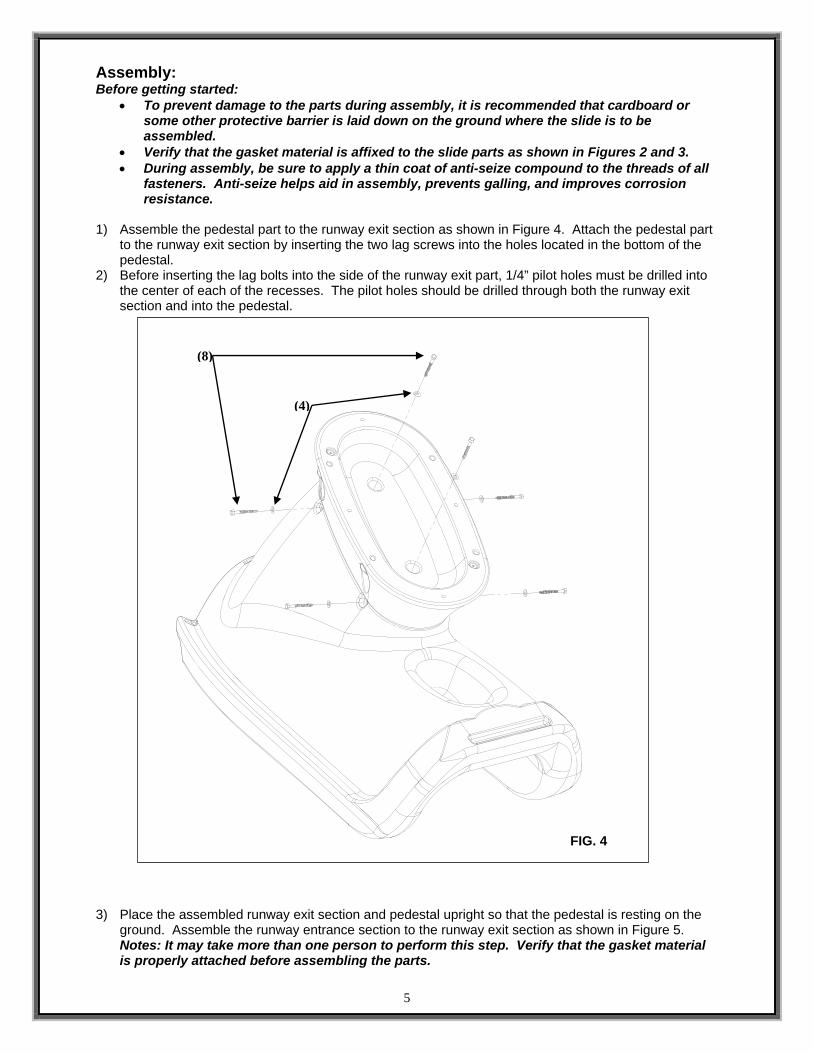
Assembly: Before getting started:
• To prevent damage to the parts during assembly, it is recommended that cardboard or some other protective barrier is laid down on the ground where the slide is to be assembled.
• Verify that the gasket material is affixed to the slide parts as shown in Figures 2 and 3. • During assembly, be sure to apply a thin coat of anti-seize compound to the threads of all
fasteners. Anti-seize helps aid in assembly, prevents galling, and improves corrosion resistance.
1) Assemble the pedestal part to the runway exit section as shown in Figure 4. Attach the pedestal part
to the runway exit section by inserting the two lag screws into the holes located in the bottom of the pedestal.
2) Before inserting the lag bolts into the side of the runway exit part, 1/4” pilot holes must be drilled into the center of each of the recesses. The pilot holes should be drilled through both the runway exit section and into the pedestal.
3) Place the assembled runway exit section and pedestal upright so that the pedestal is resting on the
ground. Assemble the runway entrance section to the runway exit section as shown in Figure 5. Notes: It may take more than one person to perform this step. Verify that the gasket material is properly attached before assembling the parts.
FIG. 4
(8)
(4)
6
4) Attach the runway entrance section to the exit section using the button head cap screws as shown in Figure 5. Tighten the button head cap screws until the lock washers are compressed. Note: Be sure to apply anti-seize to all fasteners to prevent galling.
5) Once the button head screws are tightened, insert the hex head cap screws into the underside of the runway as shown in Figure 5. Tighten the hex head cap screws until the lock washers are compressed. Note: Be sure to apply anti-seize to all fasteners to prevent galling.
6) Insert the threaded studs into each of the threaded inserts as shown in Figure 6. The studs should be screwed in by hand until they reach the bottom of the insert. If the studs cannot be threaded in by hand, pliers may be used. Before using pliers, a piece of cloth should be placed over the stud to protect the threads from damage. Note: Be sure to apply anti-seize to all fasteners to prevent galling.
FIG. 5
FIG. 6
(9) (4)
(1)(2)
(4)
(4)
(10)(1)
(4) (2)
(7)
7
7) Assemble the top ladder section to the lower ladder section as shown in Figure 7A. Insert the two carriage bolts into the steps as shown in Figure 7A. Tighten the nuts onto the carriage bolt until the lock washer is fully compressed. Note: Be sure to apply anti-seize to all fasteners to prevent galling. 8) Insert the two button head cap screws into the threaded inserts as shown in Figure 7A. Tighten the button head cap screws until snug. Note: Be sure to apply anti-seize to all fasteners to prevent galling.
9) Insert the button head cap screws into the back side of the ladder as shown in Figure 7B. Tighten the screws until snug. Note: Be sure to apply anti-seize to all fasteners to prevent galling.
FIG. 7A
FIG. 7B
(1)
(2) (4)
(6)
(4)
(5)
(6)
(4)
8
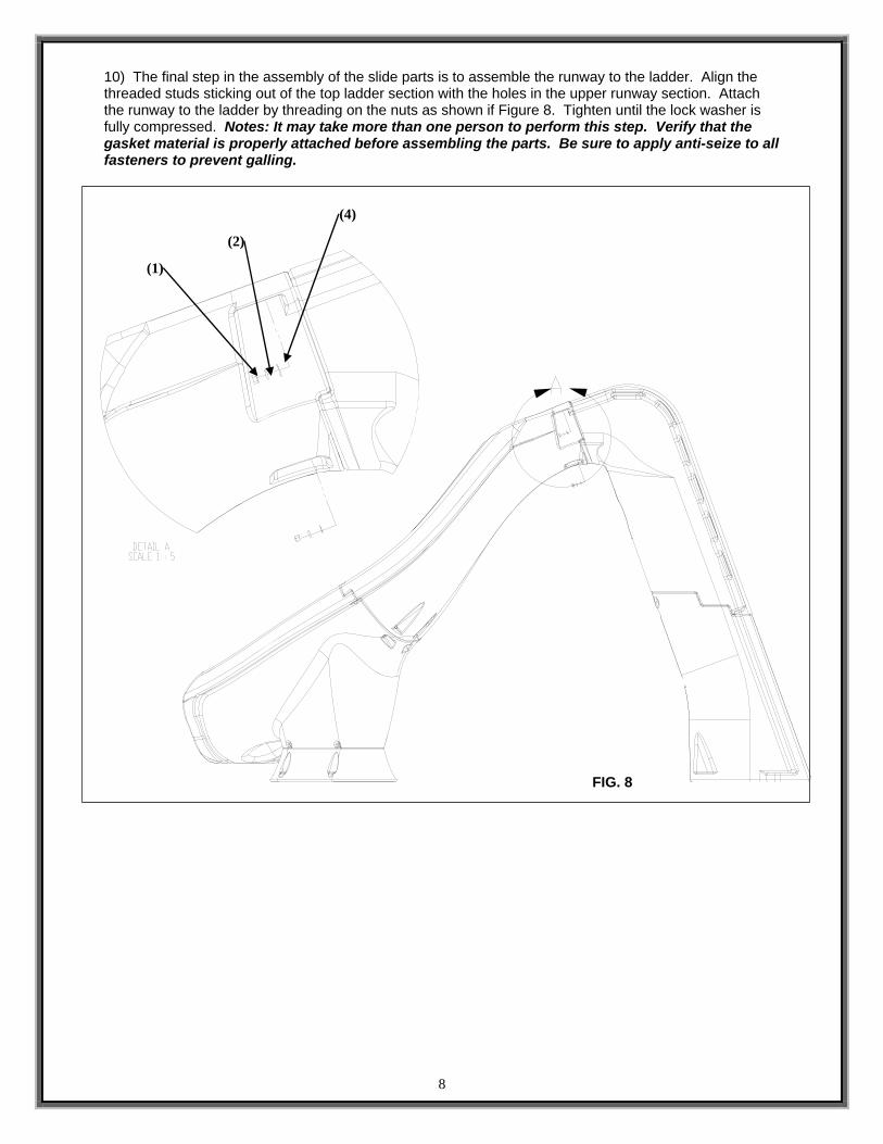
10) The final step in the assembly of the slide parts is to assemble the runway to the ladder. Align the threaded studs sticking out of the top ladder section with the holes in the upper runway section. Attach the runway to the ladder by threading on the nuts as shown if Figure 8. Tighten until the lock washer is fully compressed. Notes: It may take more than one person to perform this step. Verify that the gasket material is properly attached before assembling the parts. Be sure to apply anti-seize to all fasteners to prevent galling.
FIG. 8
(1)
(2)
(4)
9
11) First, fully assemble the water system components in the order shown in Figure 9 without gluing anything together. Assemble the water system parts to the ladder to ensure that everything fits before proceeding. Be sure that the ball valve is properly centered in the recess of the ladder. 12) Attach the pipe clamps to the ladder as shown in Figure 9, detail B. 13) Use PVC primer and glue to permanently assemble the parts together as in step 11. 14) Glue the top end of the PVC hose into the fitting in the ladder. 15) Use the pipe straps to fasten the ball valve into the ladder recess as shown in Figure 10, detail A. 16) Insert the hose into the hose clamps by firmly pushing the hose into the back of the clamp.
(11)
(14)
(11)
(13)
(15)
(21)
(22)
Fig. 9
GLUE TO FITTING IN LADDER
Fig. 10
10
PLUMBING INSTRUCTIONS
1. The Typhoon is designed for a water supply line of 1” pipe. Plumb from pool return line with a 1” PVC pipe “stubbed up” at the deck positioned at the base of the ladder. Refer to FIG. 1 on page 2. FIG. 1 is for reference only. Assembled slide should be placed in its correct location and the “stub up” location marked and installed before mounting the slide to the deck. “Stub up” should be dark grey PVC to match the plumbing assembly of the slide. Note: “Stub up” should extend above the deck 18” in height. It can be cut to proper length further in the installation process.
2. If a garden hose is to be used, a garden hose
adapter fitting is included with the slide. Assemble the pieces as shown in Figure 11 and attach to the end of the PVC plumbing assembly at the base of the ladder.
3. Proceed to the following section for ON-DECK
MOUNTING. After the slide has been mounted to the deck, attach the “stub up” as necessary to the plumbing assembly installed in the ladder.
4. The Typhoon can handle up to 20 gallons per
minute. Water flow is to be regulated using the ball valve near the base of the ladder.
Fig. 11 (18)
(17)
(16)
(22)
11
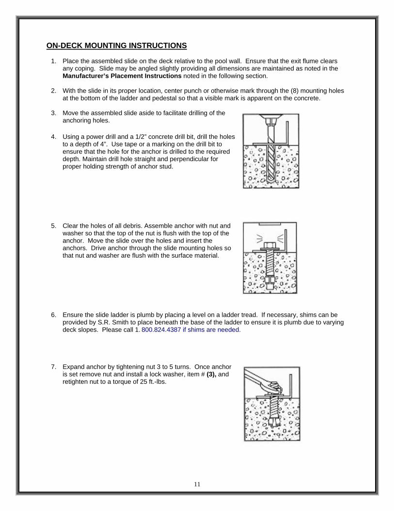
ON-DECK MOUNTING INSTRUCTIONS
1. Place the assembled slide on the deck relative to the pool wall. Ensure that the exit flume clears any coping. Slide may be angled slightly providing all dimensions are maintained as noted in the Manufacturer’s Placement Instructions noted in the following section.
2. With the slide in its proper location, center punch or otherwise mark through the (8) mounting holes
at the bottom of the ladder and pedestal so that a visible mark is apparent on the concrete.
3. Move the assembled slide aside to facilitate drilling of the anchoring holes.
4. Using a power drill and a 1/2” concrete drill bit, drill the holes
to a depth of 4”. Use tape or a marking on the drill bit to ensure that the hole for the anchor is drilled to the required depth. Maintain drill hole straight and perpendicular for proper holding strength of anchor stud.
5. Clear the holes of all debris. Assemble anchor with nut and washer so that the top of the nut is flush with the top of the anchor. Move the slide over the holes and insert the anchors. Drive anchor through the slide mounting holes so that nut and washer are flush with the surface material.
6. Ensure the slide ladder is plumb by placing a level on a ladder tread. If necessary, shims can be provided by S.R. Smith to place beneath the base of the ladder to ensure it is plumb due to varying deck slopes. Please call 1. 800.824.4387 if shims are needed.
7. Expand anchor by tightening nut 3 to 5 turns. Once anchor is set remove nut and install a lock washer, item # (3), and retighten nut to a torque of 25 ft.-lbs.
12
DECK/COPING SURFACE
3' MIN.
EXIT
RUNWAY SURFACE
PLUMBLINE
20" MAX.
WATER LEVEL
ENTRANCE
Pt.A
13'-6" MIN.9' MIN. 4'-6"
4'-6" MIN.4'-6" MIN.
MANUFACTURER’S PLACEMENT INSTRUCTIONS 1. The critical dimensions for placement of the TYPHOON are as shown in FIG.’S 12 and 13.
A. The slide exit runway surface shall not exceed twenty inches (20”) above the water surface as shown in FIG. 12.
B. The slide shall be positioned so that all water flowing off the runway exit drops into the pool. The recommended overhang is 4 inches.
C. The minimum depth of water below the exit lip of the slide shall be three feet (3’) and increase to four feet six inches (4’-6”) at Pt. A, which is a distance of four feet six inches (4’-6”) from the exit lip of the slide as shown in FIG. 12.
D. A minimum depth of four feet six inches (4’-6”) shall be maintained at a distance of nine feet (9’) along the extended centerline of the slide from Pt. A. as shown in FIG. 12.
2. A minimum clearance area in front of the slide shall be maintained at all times as follows:
A. The minimum clearance distance on either side of the extended centerline of the slide runway shall not be less than three feet six inches (3’-6”) at a point no less than two feet six inches (2’-6”) from the exit lip of the slide and extending a distance of thirteen feet six inches (13’-6”) in front of the slide as shown in FIG. 13.
B. The minimum clearance area in front of a properly installed diving board
on an inground swimming pool is a minimum distance of three feet six inches (3’-6”) on either side of the board’s centerline as shown in FIG. 14. Pt. C extends a minimum distance of “C” from the tip end of the board as shown in FIG. 14. The width distance “W” on either side of Pt. C is given in CHART 1 and shown in FIG. 14.
FIG. 12
FIG. 13
13
“C” DIMENSION FOR BOARD = AB + BC “W” DIMENSION FOR BOARD = WIDTH AT PT.C
C. The minimum clearance area of a slide or diving board shall not intersect any coping or rope and float line as shown in FIG. 15. The minimum clearance area of a slide or diving board may intersect each other provided that they are not used simultaneously.
CHART 1 BOARD MINIMUM CLEARANCE AREA
POOL TYPE “C” DIMENSION “W” DIMENSION I 14’-6” 5’-0” II 14’-6” 6’-0” III 16’-6” 6’-0” IV 18’-6” 7’-6” V 21’-0” 7’-6”
See Article 5 contained in ANSI/NSPI-5 2003 STANDARD FOR RESIDENTIAL INGROUND SWIMMING POOLS and refer to FIGURE 3 and Table 1 for Minimum Water Envelope Dimensions AB, BC and Width at Point C.
1. Inspect the runway for visible cracks or tears. 2. Inspect the slide for sharp edges, protrusions, cracks or tears. 3. Inspect all fasteners to make sure they are fully tightened. 4. Inspect the ladder for rigidity and attachment. 5. Measure the following dimensions and compare with the Manufacturer’s Placement Instructions
on pages 6 and 7. • Measure the depth of water in front of the slide exit. (4’-6” min. depth at a distance of 4’-
6” from exit end of slide.) • Measure the height of the slide runway exit above the water. (20” max.) • Measure the distance between the slide centerline and the edge of other pool equipment.
6. Observe the position of the exit of the slide as shown in FIG.’S 12, 13 and 15 on pages 12 and 13.
IMPORTANT
PERSONALLY GIVE TO SLIDE OWNER THE TYPHOON OWNER’S MANUAL, THE WARRANTY CARD AND ANSWER ALL QUESTIONS.