NT 02010 VKMA/C 02179 – VKMA 02190 – VKMC 02190-2 – VKMA 02191 – VKMC 02191-2 – VKMA/C 02192 – VKMA 02193 – VKMC 02193-2 – VKMA/C 02194 – VKMA 02195 – VKMC 02195-2 – VKMA 02196 – VKMC 02196-2 – VKMA 02197 – VKMC 02197-2 – VKMA/C 02198 – VKMA 02199 – VKMC 02199-2 Removal 1) Disconnecting the battery according to the vehicle manufacturing guidelines. 2) Prepare the vehicle for the timing replacement according to the vehicle manufacturing guidelines. 3) According to the vehicle (Alfa Romeo, Fiat and Lancia) and engine being repaired (1.9 JTD/ Multijet or 2.4 JTD), remove the following items if required: drive train tie-rod, electronic engine management module, bumpers and bumper damper 4) Lock the flywheel using the appropriate locking tool (5) (Fig. B). 5) Remove the crankshaft pulley and the tool (5) 6) Remove the timing system casing(s). 7) Turn cylinder No. 1 to TDC by aligning the marks (6) (Fig. C) on the camshaft and the inner timing casing. 8) Alfa Romeo 147 and 156: – Remove the auxiliary belt idler roller and the lower timing casing. 9) Check that the pin (7) on the crankshaft sprocket is directed towards the bottom (Fig. D). 10) Loosen the tensioner roller securing nut (16) (Fig. A), slacken and remove the timing belt (1) then the tensioner (2). 11) Remove the idler roller (3) (Fig. A). 12) Removing the water pump (VKMC 02179/02190/02191/02192): firstly bleed the cooling circuit, check it is clean, and clean if required; secondly fully loosen the water pump fastening bolts (10) and remove the pump (4) (Fig. A). B D C Install Confidence A (5): ref. 1860898000 / 1820630000 (Alfa 156)/ (12)/(13): ref. 1860905000/ (14): ref. 1860905010/ (10): 15 Nm/ (16): 25 Nm (M8); 42-53 Nm (M10) (18): 20 Nm/ (20): 25 Nm/ Alfa Romeo / Fiat / Lancia VKMA 02179 VKMA 02193 VKMA 02191 VKMA 02195 VKMA 02190 VKMA 02194 VKMA 02198 VKMA 02199 VKMA 02192 VKMA 02197
Removal1) Disconnecting the battery according to the
vehicle manufacturing guidelines.2) Prepare the vehicle for the timing replacement
according to the vehicle manufacturing guidelines.
3) According to the vehicle (Alfa Romeo, Fiat and Lancia) and engine being repaired (1.9 JTD/Multijet or 2.4 JTD), remove the following items if required: drive train tie-rod, electronic engine management module, bumpers and bumper damper
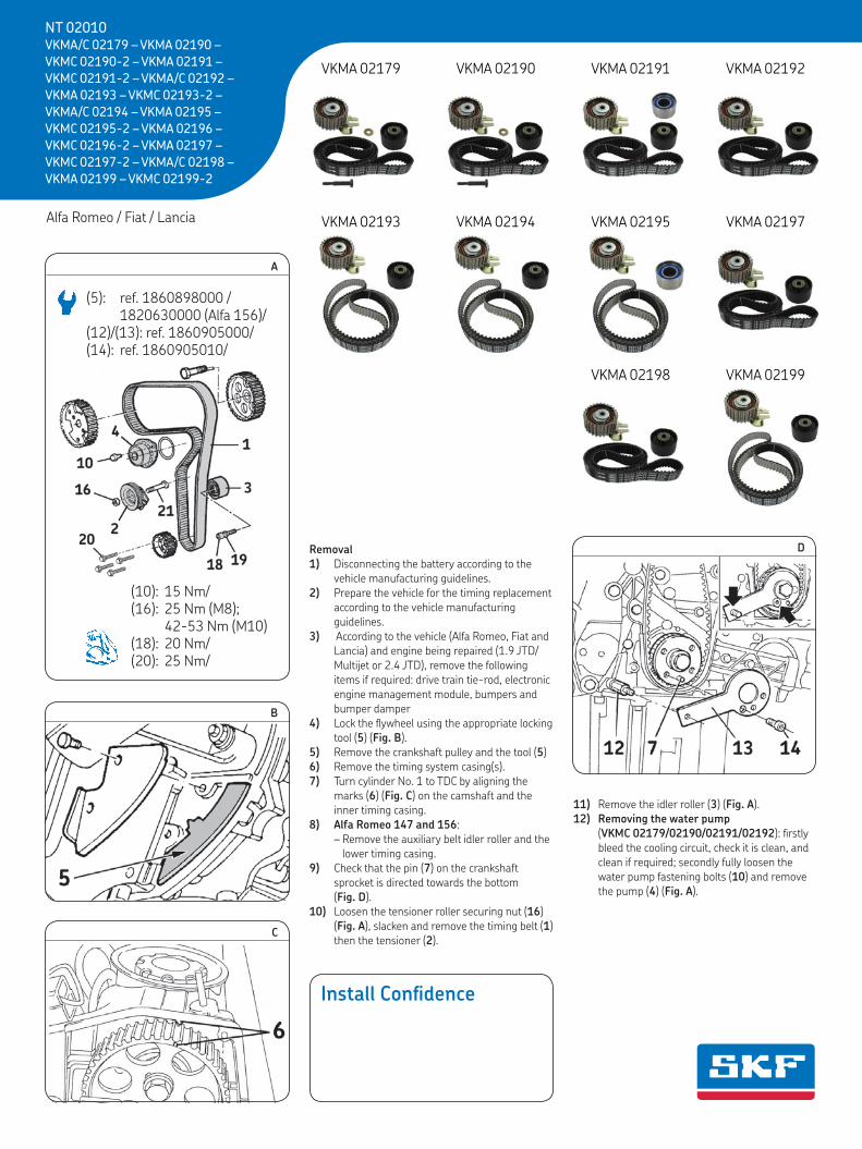
4) Lock the flywheel using the appropriate locking tool (5) (Fig. B).
5) Remove the crankshaft pulley and the tool (5)6) Remove the timing system casing(s).7) Turn cylinder No. 1 to TDC by aligning the
marks (6) (Fig. C) on the camshaft and the inner timing casing.
8) Alfa Romeo 147 and 156: – Remove the auxiliary belt idler roller and the
lower timing casing.9) Check that the pin (7) on the crankshaft
sprocket is directed towards the bottom (Fig. D).
10) Loosen the tensioner roller securing nut (16) (Fig. A), slacken and remove the timing belt (1) then the tensioner (2).
11) Remove the idler roller (3) (Fig. A).12) Removing the water pump
(VKMC 02179/02190/02191/02192): firstly bleed the cooling circuit, check it is clean, and clean if required; secondly fully loosen the water pump fastening bolts (10) and remove the pump (4) (Fig. A).
REMOVAL1) Disconnect the battery according to thevehicle manufacturing guidelines.2) Prepare the vehicle for the timing replacementaccording to the vehicle manufacturing guide-lines.3) According to the vehicle (Alfa Romeo, Fiatand Lancia) and engine being repaired (1.9JTD/Multijet or 2.4 JTD), remove the followingitems if required: drive train tie-rod, electronicengine management module, bumpers andbumper damper.4) Lock the flywheel using the appropriatelocking tool (5) (Fig. B).5) Remove the crankshaft pulley and thetool (5).6) Remove the timing system casing(s).7) Turn cylinder No. 1 to TDC by aligning themarks (6) (Fig. C) on the camshaft and theinner timing casing.8) Alfa Romeo 147 and 156:Remove the auxiliary belt idler roller and thelower timing casing.9) Check that the pin (7) on the crankshaftsprocket is directed towards the bottom (Fig. D).10) Loosen the tensioner roller securing nut(16) (Fig. A), slacken and remove the timingbelt (1) then the tensioner (2).11) Remove the idler roller (3) (Fig. A).12) Removing the water pump (VKMC02179/02190-2/02191-2/02192/02193-2 /02194 /02195-2 /02196-2 /02197-2/02198/02199-2): firstly bleed the coolingcircuit, check it is clean, and clean if required;secondly fully loosen the water pump fasteningbolts (10) and remove the pump (4) (Fig. A).
REFITTINGCaution! first clean the bearing surfaces of therollers.13) Refitting the water pump: Firstly, fit thenew water pump (4), apply the torque 15 N.mto the waterpump bolts (10); then check thatthe water pump pulley runs properly, and hasno hard or locking spots.14) Fit the new tensioner roller (2) by slightlytightening its securing nut (16) (Fig. A) (adjustthe pin (8) located on the engine down to thebottom of the slot on the roller rear plate)(Fig. E). 15) Fit the new idler roller (3) and it’s newwasher (19) and new bolt (18) (if VKMA/C02179 - VKMA 02190 - VKMC 02190-2) thentighten the bolt (18) to 20 N.m (Fig. A).16) Fit the new timing belt (1) by applying thefollowing sequence: crankshaft sprocket, idlerroller (3), camshaft sprocket (9), injection pumpsprocket, water pump sprocket (4) then thetensioner roller (2) (Fig. A).17) Remove the oil pump bolt (11) (Fig. F).18) Fit the tool (12) in the place of the oil pumpbolt (11) (Fig. F) then position and immobilisethe tool (13) on the crankshaft sprocket withthe calibrated bolt (14) (Fig. D).19) Check the alignment of the marks (6)(Fig. C) on the camshaft and the inner timing
casing.20) Turn the tensioner roller (2) using a flatscrewdriver to set the moving pointer (15) tomaximum tension position (Fig. G) and tightenthe fastening nut (16) to 25 N.m (M8) or 42-53 N.m (M10).21) Remove tools (12), (13) and (14) (Fig. D)then refit the oil pump bolt (11) (Fig. F).22) Turn the crankshaft by 2 turns in the enginerotation direction until cylinder No. 1 isreturned to TDC.23) Loosen slightly the tensioner roller securingnut (16) while holding it in position using a flatscrewdriver. Release the tensioner roller untilthe moving pointer (15) is aligned with theindicator mark (17) (Fig. H).25) Tighten the tensioner roller fastening nut(16) to 25 N.m (M8) or 42-53 N.m (M10) andturn regularly the crankshaft by 2 turns in theengine rotation direction until cylinder No. 1 isreturned to TDC. 26) Check the tensioner roller adjustment (themoving pointer (15) must be aligned with theindicator marker (17) (Fig. H)) and check thetiming marks (Fig. C) and that the pin (7) on thecrankshaft sprocket is directed towards thebottom (Fig. D).27) Refit the flywheel locking tool (5) (Fig. B)then the crankshaft pulley, tighten its fasteningbolts (20) to 25 N.m (Fig. A).28) Remove the flywheel locking tool (5).29) Refit the elements removed in reverseorder to removal.30) Fill the cooling circuit with the permanentfluid recommended.31) Check the circuit’s leak-tightness when theengine reaches its running temperature andsecure the level of coolant when the engine isat ambient temperature (20°C).
NOTICES: "The SKF KITS are designed for automotive repair professionals, and must be fitted using tooling used bythese professionals. These instructions are NOT designed for private individuals. Any fitting operation not performed
by an automotive repair professional will give rise neither to guarantees, nor involve the SKF company, wavering its liability incase of non compliance with the instructions contained in this manual. This document is the exclusive property of SKF. Anyrepresentation, partial or full reproduction, is forbidden without prior written consent from SKF."
AVIS : "Les KITS SKF sont destinés aux professionnels de la réparation automobile, et doivent être montés avecles outillages que possèdent ces professionnels. En aucun cas ces instructions ne sont destinées à des particuliers.
Tout montage non effectué par un professionnel de la réparation automobile ne peut ni donner lieu à garantie, ni mettre en causela société SKF qui dégage sa responsabilité en cas de non suivi des instructions contenues dans la présente notice. Ce documentest la propriété exclusive de la société SKF. Toute représentation, reproduction partielle ou intégrale est interdite sans le consen-tement écrit de la société SKF."
HINWEIS: „Die SKF-KITS sind für Berufsmechaniker im Automobilreparaturbereich bestimmt; sie müssen mitWerkzeugen ausgestattet werden, die von diesen Mechanikern benutzt werden. Diese Anleitung ist auf keinen Fall für
Privatpersonen bestimmt. Für Montagen, die nicht von Berufsmechanikern des Automobilreparaturbereichs ausgeführt werden,kann weder die Garantie in Anspruch genommen noch die Firma SKF verantwortlich gemacht werden, die jede Haftung im Fallder Nichtbeachtung der in dieser Anleitung enthaltenen Anweisungen ablehnt. Dieses Dokument ist das ausschließliche Eigentumder Firma SKF. Jede Darstellung und Wiedergabe, ob ganz oder teilweise, ist ohne das schriftliche Einverständnis der Firma SKFuntersagt.“
GB F DNT 02010GB - INSTALLATION INSTRUCTIONSF - INSTRUCTIONS DE MONTAGED - EINBAUANLEITUNGI - ISTRUZIONI PER IL MONTAGGIOSP - INSTRUCCIONES DE MONTAJENL - MONTAGEINSTRUCTIESS - MONTERINGS INSTRUKTION
DEPOSE1) Débrancher la batterie conformément auxinstructions constructeur.2) Préparer le véhicule pour le remplacementdu système de distribution selon les instruc-tions constructeur.3) Tourner le vilebrequin dans le sens de rota-tion du moteur jusqu'au PMH. Vérifier l'aligne-ment des repères (3) de la roue dentée d'arbreà cames (Fig. B) et (4) de la poulie de vilebre-quin (Fig. C).Nota : si nécessaire, tourner le vilebrequin d'untour supplémentaire afin d'obtenir l'alignementdes repères.4) Déposer la poulie de vilebrequin.5) Desserrer l’écrou (13) (Fig. D) du galet ten-deur et déposer la courroie de distribution.6) Déposer le galet tendeur (2).7) Déposer le goujon (15) (Fig. A).8) Démontage de la pompe à eau (VKMC01113-1/2): purger le circuit de refroidisse-ment, vérifier qu'il soit propre, et nettoyer sinécessaire, ensuite desserrer complètement lesvis (16) de la pompe à eau (12) et retirer la(Fig. A).
REPOSEAttention : Nettoyer soigneusement les surfa-ces d'appui du galet tendeur. 9) Remontage de la pompe à eau : monter lanouvelle pompe à eau (12), serrer les vis (16)au couple de 15 N.m, puis vérifier que la pou-lie de la pompe à eau tourne librement, et n’apas de points durs ou bloquant (Fig. A).10) Monter et serrer le goujon neuf (15) aucouple de 15 N.m (Fig. A).11) Vérifier l'alignement des repères de calage(3) (Fig. B).12) Reposer le galet tendeur neuf (2) : - Placer l'ergot de positionnement (5) dans l'o-rifice (6) du bloc-moteur (Fig. D). - Mettre en place la rondelle neuve (14) et l’é-crou neuf (13) (Fig. D).13) Placer la courroie neuve (1) sur le pignonde vilebrequin.14) Reposer le carter de distribution inférieuret reposer puis serrer la poulie de vilebrequin.15) Vérifier l'alignement des repères de calage(4) (Fig. C). Poursuivre l'installation de la cour-roie dans l'ordre suivant : pignon de pompe àeau, galet tendeur et roue dentée d’arbre àcames.16) Tendre la courroie de distribution (1) :- Tourner le cadran de réglage (7) (Fig. D) du
galet tendeur (2) dans le sens anti-horairejusqu’en butée puis dans le sens horairejusqu’en butée, ceci 5 fois, à l’aide de laclé (8).
- Tourner le cadran de réglage (7) du galettendeur (2) à fond dans le sens anti-horairepuis relacher le galet tendeur jusqu'à ce quel'index mobile (9) soit aligné avec l'encoche(11) (Fig. E).
17) Serrer l’écrou de fixation neuf (13) du galettendeur (2) au couple de 20 N.m (Fig. D).18) Effectuer deux tours de vilebrequin dans le
sens de rotation du moteur jusqu’au PMH.Vérifier l'alignement des repères (3) (Fig. B) et(4) (Fig. C).19) Vérifier le réglage du galet tendeur (2) :l'index mobile (9) doit être aligné avec l'encoche(11) (Fig. G).20) Si les repères du galet tendeur ne sont pasalignés, déposer la courroie de distribution.Recommencer ensuite l'opération de réglage dela tension depuis l'étape 13).21) Effectuer le remontage des éléments dépo-sés dans l’ordre inverse du démontage.22) Remplir le circuit de refroidissement avec leliquide recommandé.23) Vérifier l'étanchéité du circuit lorsque lemoteur atteint la température de fonctionne-ment et ajuster le niveau de liquide de refroi-dissement lorsque le moteur est à températureambiante (20° C).
AUSBAU1) Batterie abklemmen nach Werksvorschrift.2) Fahrzeug nach Werksvorschrift vorbereitenfür Zahnriemen Wechsel.3) Kurbelwelle im Uhrzeigersinn drehen bisOTStellung erreicht ist. Ausrichtung derEinstellmarkierungen (3) von Zahnrad derNockenwelle (Abb. B), (4) von Kurbelwellen-scheibe (Abb. C) prüfen.Anmerkung: Falls erforderlich, Kurbelwelle einezusätzliche Umdrehung bewegen, damit dieMarkierungen übereinstimmen.4) Kurbelwellescheibe ausbauen.5) Mutter (13) von Spannrolle lösen (Abb. D)und Zahnriemen ausbauen.6) Spannrolle (2) ausbauen.7) Bolzen (15) ausbauen (Abb. A).8) Wasserpumpe Entfernen (VKMC 01113-1/2). Erst Kühlerkreislauf entleeren, aufSauberkeit prüfen und erforderlichenfallsreinigen. Befestigungsschrauben (16) vollherausdrehen und Wasserpumpe (12)abnehmen (Abb. A).
EINBAUAchtung: Auflageflächen der Rollen sorgfältigreinigen.9) Einbau der Wasserpumpe. NeueWasserpumpe (12) montieren und Befestigungs-schrauben (16) mit 15 N.m anziehen. Prüfen obder Wasserpumpe weich dreht und keineharten Stellen aufweist (Abb. A). 10) Neue Bolzen (15) einbauen und mit 15 N.manziehen (Abb. A).11) Ausrichtung der Einstellmarkierungen (3)kontrollieren (Abb. B).12) Neue Spannrolle (2) einbauen: - Einstellnase (5) in Schlitz (6) von Motorblock
einrasten (Abb. D). - Die neue Scheibe (14) und neuen Mutter (13)
einbauen.13) Neuen Zahnriemen (1) auf Kurbelwellenradsetzen.14) Unteres Steuergehäuse einbauen und dannKurbelwellenscheibe einbauen und festziehen.15) Ausrichtung der Einstellmarkierungen (4)kontrollieren (Abb. C). Einbau von Zahnriemenin dieser Reihenfolge fortsetzen: Zahnrad derWasserpumpe, Spannrolle und Zahnrad derNockenwelle.16) Zahnriemen (1) spannen.- Einstellplatte (7) (Abb. D) von Spannrolle (2)
entgegen dem Uhrzeigersinn ......??????.- Schließlich Einstellplatte (7) von Spannrolle
(2) entgegen dem Uhrzeigersinn ....????.17) Den neuen Befestigungsmutter (13) desSpannrolle (2) mit einem Drehmoment von20 N.m anziehen (Abb. D).18) Mit Kurbelwelle zwei Umdrehungen imUhrzeigersinn machen bis OT-Stellung erreichtist. Ausrichtung der Einstellmarkierungen (3)
(Abb. B) und (4) (Abb. C) kontrollieren.19) Einstellung der Spannrolle (2) prüfen:bewegliche Markierung (9) muss mit Kerbe(11) ausgerichtet sein (Abb. G).20) Wenn die Markierungen der Spannrollenicht übereinstimmen, Zahnriemen ausbauen.Wiederholen Sie dann den Vorgang derSpannungseinstellung ab Schritt 13).21) Wiedereinbau der ausgebauten Elemente inumgekehrter Reihenfolge vornehmen.22) Kühlerkreislauf mit der vorgeschriebenenKühlflüssigkeit einfüllen 23) Bei Betriebstemperatur des MotorsDichtheit des Kreislaufs sorgfaltig prüfen.Kühlflüssigkeit Niveau kontrollieren beiabgekühltem Motor. (Raumtemperatur 20° C).
REMOVAL1) Disconnecting the battery according to themanufacturing guidelines.2) Prepare the vehicle for the timingreplacement according to the manufacturingguidelines.3) Turn the crankshaft in the engine rotationdirection up to TDC. Check the alignment of thetiming marks of the camshaft sprocket (3)(Fig. B) and of the crankshaft pulley (4) (Fig. C).Note: If necessary, turn the crankshaft oneextra turn to align the marks.4) Remove the crankshaft pulley.5) Slacken the tensioner roller nut (13) (Fig. D)and remove the timing belt.6) Remove the tensioner roller (2).7) Remove the stud (15) (Fig. A).8) Removing the water pump (for VKMC01113-1/2): firstly, bleed the cooling circuit,check it is clean, and clean if required; secondly,fully loosen the water pump fastening bolts(16) and remove the pump (12) (Fig. A).
REFITTINGCaution: Carefully clean the bearing surfaces ofthe tensioner roller.9) Refitting the water pump: Firstly, fit thenew water pump (12), tighten the waterpumpbolts (16) to the torque of 15 N.m, then checkthat the water pump pulley runs properly, andhas no hard or locking spots.10) Fit and tighten the new stud (15) to thetorque of 15 N.m (Fig. A).11) Check the alignment of the timing marks(3) (Fig. B).12) Fit the new tensioner roller (2): - Fit the positioning pin (5) in the hole (6) of
the engine block (Fig. D). - Fit the new washer (14) and the new nut (13)
(Fig. D).13) Fit the new belt (1) on the crankshaftsprocket.14) Refit the lower timing casing and refit thentighten the crankshaft pulley.15) Check the alignment of the timing marks(4) (Fig. C). Continue installing the belt in thefollowing order: water pump sprocket,tensioner roller and camshaft sprocket.16) Tighten the timing belt (1):- Turn the adjustment dial (7) (Fig. D) of the
tensioner roller (2) anti-clockwise andclockwise fully 5 times from maximum posi-tion to maximum position by using thewrench (8).
- Turn the adjustment dial (7) of the tensionerroller (2) fully anti-clockwise and thenslacken the tensioner until the movingpointer (9) is aligned with the notch (11)(Fig. E).
17) Tighten the new fastening nut (13) of thetensioner roller (2) to a torque of 20 N.m(Fig. D).18) Rotate the crankshaft two turns in theengine rotation direction up to TDC. Check thealignment of the marks (3) (Fig. B) and (4)(Fig. C).
19) Check the tensioner roller setting (2): themoving pointer (9) must be aligned with thenotch (11) to make sure the tension is set(Fig. G).20) If the marks of the tensioner roller are notaligned, remove the timing belt. Then restartthe adjustment operation from step 13).21) Refit the elements removed in reverseorder to removal. 22) Fill the cooling circuit with the permanentfluid recommended.23) Check the circuit’s leak-tightness when theengine reaches its running temperature andsecure the level of coolant when the engine isat ambient temperature (20° C).
GB F D
NT 01020 VKMA 01113 - VKMC 01113-1 /-2
VKMA 01113 = 1 x + 1 x + 1 x + 1 x + 1 x
VKMC 01113-1 /-2 = 1 x + 1 x + 1 x + 1 x + 1 x + 1 x
NOTICES: "The SKF KITS are designed for automotive repair professionals, and must be fitted using tooling used bythese professionals. These instructions are NOT designed for private individuals. Any fitting operation not performed
by an automotive repair professional will give rise neither to guarantees, nor involve the SKF company, wavering its liability incase of non compliance with the instructions contained in this manual. This document is the exclusive property of SKF. Anyrepresentation, partial or full reproduction, is forbidden without prior written consent from SKF."
AVIS : "Les KITS SKF sont destinés aux professionnels de la réparation automobile, et doivent être montés avecles outillages que possèdent ces professionnels. En aucun cas ces instructions ne sont destinées à des particuliers.
Tout montage non effectué par un professionnel de la réparation automobile ne peut ni donner lieu à garantie, ni mettre en causela société SKF qui dégage sa responsabilité en cas de non suivi des instructions contenues dans la présente notice. Ce documentest la propriété exclusive de la société SKF. Toute représentation, reproduction partielle ou intégrale est interdite sans le consen-tement écrit de la société SKF."
HINWEIS: „Die SKF-KITS sind für Berufsmechaniker im Automobilreparaturbereich bestimmt; sie müssen mitWerkzeugen ausgestattet werden, die von diesen Mechanikern benutzt werden. Diese Anleitung ist auf keinen Fall für
Privatpersonen bestimmt. Für Montagen, die nicht von Berufsmechanikern des Automobilreparaturbereichs ausgeführt werden,kann weder die Garantie in Anspruch genommen noch die Firma SKF verantwortlich gemacht werden, die jede Haftung im Fallder Nichtbeachtung der in dieser Anleitung enthaltenen Anweisungen ablehnt. Dieses Dokument ist das ausschließliche Eigentumder Firma SKF. Jede Darstellung und Wiedergabe, ob ganz oder teilweise, ist ohne das schriftliche Einverständnis der Firma SKFuntersagt.“
GB F DNT 01020GB - INSTALLATION INSTRUCTIONSF - INSTRUCTIONS DE MONTAGED - EINBAUANLEITUNGI - ISTRUZIONI PER IL MONTAGGIOSP - INSTRUCCIONES DE MONTAJENL - MONTAGEINSTRUCTIESS - MONTERINGS INSTRUKTION
REMOVAL1) Disconnect the battery according to thevehicle manufacturing guidelines.2) Prepare the vehicle for the timing replacementaccording to the vehicle manufacturing guide-lines.3) According to the vehicle (Alfa Romeo, Fiatand Lancia) and engine being repaired (1.9JTD/Multijet or 2.4 JTD), remove the followingitems if required: drive train tie-rod, electronicengine management module, bumpers andbumper damper.4) Lock the flywheel using the appropriatelocking tool (5) (Fig. B).5) Remove the crankshaft pulley and thetool (5).6) Remove the timing system casing(s).7) Turn cylinder No. 1 to TDC by aligning themarks (6) (Fig. C) on the camshaft and theinner timing casing.8) Alfa Romeo 147 and 156:Remove the auxiliary belt idler roller and thelower timing casing.9) Check that the pin (7) on the crankshaftsprocket is directed towards the bottom (Fig. D).10) Loosen the tensioner roller securing nut(16) (Fig. A), slacken and remove the timingbelt (1) then the tensioner (2).11) Remove the idler roller (3) (Fig. A).12) Removing the water pump (VKMC02179/02190-2/02191-2/02192/02193-2 /02194 /02195-2 /02196-2 /02197-2/02198/02199-2): firstly bleed the coolingcircuit, check it is clean, and clean if required;secondly fully loosen the water pump fasteningbolts (10) and remove the pump (4) (Fig. A).
REFITTINGCaution! first clean the bearing surfaces of therollers.13) Refitting the water pump: Firstly, fit thenew water pump (4), apply the torque 15 N.mto the waterpump bolts (10); then check thatthe water pump pulley runs properly, and hasno hard or locking spots.14) Fit the new tensioner roller (2) by slightlytightening its securing nut (16) (Fig. A) (adjustthe pin (8) located on the engine down to thebottom of the slot on the roller rear plate)(Fig. E). 15) Fit the new idler roller (3) and it’s newwasher (19) and new bolt (18) (if VKMA/C02179 - VKMA 02190 - VKMC 02190-2) thentighten the bolt (18) to 20 N.m (Fig. A).16) Fit the new timing belt (1) by applying thefollowing sequence: crankshaft sprocket, idlerroller (3), camshaft sprocket (9), injection pumpsprocket, water pump sprocket (4) then thetensioner roller (2) (Fig. A).17) Remove the oil pump bolt (11) (Fig. F).18) Fit the tool (12) in the place of the oil pumpbolt (11) (Fig. F) then position and immobilisethe tool (13) on the crankshaft sprocket withthe calibrated bolt (14) (Fig. D).19) Check the alignment of the marks (6)(Fig. C) on the camshaft and the inner timing
casing.20) Turn the tensioner roller (2) using a flatscrewdriver to set the moving pointer (15) tomaximum tension position (Fig. G) and tightenthe fastening nut (16) to 25 N.m (M8) or 42-53 N.m (M10).21) Remove tools (12), (13) and (14) (Fig. D)then refit the oil pump bolt (11) (Fig. F).22) Turn the crankshaft by 2 turns in the enginerotation direction until cylinder No. 1 isreturned to TDC.23) Loosen slightly the tensioner roller securingnut (16) while holding it in position using a flatscrewdriver. Release the tensioner roller untilthe moving pointer (15) is aligned with theindicator mark (17) (Fig. H).25) Tighten the tensioner roller fastening nut(16) to 25 N.m (M8) or 42-53 N.m (M10) andturn regularly the crankshaft by 2 turns in theengine rotation direction until cylinder No. 1 isreturned to TDC. 26) Check the tensioner roller adjustment (themoving pointer (15) must be aligned with theindicator marker (17) (Fig. H)) and check thetiming marks (Fig. C) and that the pin (7) on thecrankshaft sprocket is directed towards thebottom (Fig. D).27) Refit the flywheel locking tool (5) (Fig. B)then the crankshaft pulley, tighten its fasteningbolts (20) to 25 N.m (Fig. A).28) Remove the flywheel locking tool (5).29) Refit the elements removed in reverseorder to removal.30) Fill the cooling circuit with the permanentfluid recommended.31) Check the circuit’s leak-tightness when theengine reaches its running temperature andsecure the level of coolant when the engine isat ambient temperature (20°C).
NOTICES: "The SKF KITS are designed for automotive repair professionals, and must be fitted using tooling used bythese professionals. These instructions are NOT designed for private individuals. Any fitting operation not performed
by an automotive repair professional will give rise neither to guarantees, nor involve the SKF company, wavering its liability incase of non compliance with the instructions contained in this manual. This document is the exclusive property of SKF. Anyrepresentation, partial or full reproduction, is forbidden without prior written consent from SKF."
AVIS : "Les KITS SKF sont destinés aux professionnels de la réparation automobile, et doivent être montés avecles outillages que possèdent ces professionnels. En aucun cas ces instructions ne sont destinées à des particuliers.
Tout montage non effectué par un professionnel de la réparation automobile ne peut ni donner lieu à garantie, ni mettre en causela société SKF qui dégage sa responsabilité en cas de non suivi des instructions contenues dans la présente notice. Ce documentest la propriété exclusive de la société SKF. Toute représentation, reproduction partielle ou intégrale est interdite sans le consen-tement écrit de la société SKF."
HINWEIS: „Die SKF-KITS sind für Berufsmechaniker im Automobilreparaturbereich bestimmt; sie müssen mitWerkzeugen ausgestattet werden, die von diesen Mechanikern benutzt werden. Diese Anleitung ist auf keinen Fall für
Privatpersonen bestimmt. Für Montagen, die nicht von Berufsmechanikern des Automobilreparaturbereichs ausgeführt werden,kann weder die Garantie in Anspruch genommen noch die Firma SKF verantwortlich gemacht werden, die jede Haftung im Fallder Nichtbeachtung der in dieser Anleitung enthaltenen Anweisungen ablehnt. Dieses Dokument ist das ausschließliche Eigentumder Firma SKF. Jede Darstellung und Wiedergabe, ob ganz oder teilweise, ist ohne das schriftliche Einverständnis der Firma SKFuntersagt.“
GB F DNT 02010GB - INSTALLATION INSTRUCTIONSF - INSTRUCTIONS DE MONTAGED - EINBAUANLEITUNGI - ISTRUZIONI PER IL MONTAGGIOSP - INSTRUCCIONES DE MONTAJENL - MONTAGEINSTRUCTIESS - MONTERINGS INSTRUKTION
21) Remove tools (12), (13) and (14) (Fig. D) then refit the oil pump bolt (11) (Fig. F).
22) Turn the crankshaft by 2 turns in the engine rotation direction until cylinder No. 1 is returned to TDC.
23) Loosen slightly the tensioner roller securing nut (16) while holding it in position using a flat screwdriver. Release the tensioner roller until the moving pointer (15) is aligned with the indicator mark (17) (Fig. H).
25) Tighten the tensioner roller fastening nut (16) to 25 Nm (M8) or 42-53 Nm (M10). And turn regularly the crankshaft by 2 turns in the engine rotation direction until cylinder No. 1 is returned to TDC.
26) Check the tensioner roller adjustment (the moving pointer (15) must be aligned with the indicator marker (17) (Fig. H)) and check the timing marks Fig. C) and that the pin (7) on the crankshaft sprocket is directed towards the bottom (Fig. D)
27) Refit the flywheel locking tool (5) (Fig. B) then the crankshaft pulley, tighten its fastening bolts (20) to 25 Nm.
28) Remove the flywheel locking tool (5).29) Refit the elements removed in reverse order to
removal.30) Fill the cooling circuit with the permanent fluid
recommended.31) Check the circuit’s leak-tightness when the
engine reaches its running temperature and secure the level of coolant when the engine is at ambient temperature (20 °C).
RefittingCaution! First clean the bearing surfaces of therollers.
13) Refitting the water pump: Firstly, fit the new water pump (4), apply the torque 15 N.m to the waterpump bolts (10); then check that the water pump pulley runs properly, and has no hard or locking spots.
14) Fit the new tensioner roller (2) and its stud (21), slightly tightening its securing nut (16) (Fig. A) (adjust the pin (8) located on the engine down to the bottom of the slot on the roller rear plate) (Fig. E).
15) Fit the new idler roller (3) and it’s new washer (19) and new bolt (18) (if VKMA/C 02179/02190) then tighten the bolt (18) to 20 Nm (Fig. A).
16) Fit the new timing belt (1) by applying the following sequence: crankshaft sprocket, idler roller (3), camshaft sprocket (9), injection pump sprocket, water pump sprocket (4) then the tensioner roller (2) (Fig. A).
17) Remove the oil pump bolt (11) (Fig. F).18) Fit the tool (12) in the place of the oil pump
bolt (11) (Fig. F) then position and immobilise the tool (13) on the crankshaft sprocket with the calibrated bolt (14) (Fig. D).
19) Check the alignment of the marks (6) (Fig. C) on the camshaft and the inner timing casing.
20) Turn the tensioner roller (2) using a flat screwdriver to set the moving pointer (15) to maximum tension position (Fig. G) and tighten the fastening nut (16) to 25 Nm (M8) or 42-53 Nm (M10).
F
REMOVAL1) Disconnect the battery according to thevehicle manufacturing guidelines.2) Prepare the vehicle for the timing replacementaccording to the vehicle manufacturing guide-lines.3) According to the vehicle (Alfa Romeo, Fiatand Lancia) and engine being repaired (1.9JTD/Multijet or 2.4 JTD), remove the followingitems if required: drive train tie-rod, electronicengine management module, bumpers andbumper damper.4) Lock the flywheel using the appropriatelocking tool (5) (Fig. B).5) Remove the crankshaft pulley and thetool (5).6) Remove the timing system casing(s).7) Turn cylinder No. 1 to TDC by aligning themarks (6) (Fig. C) on the camshaft and theinner timing casing.8) Alfa Romeo 147 and 156:Remove the auxiliary belt idler roller and thelower timing casing.9) Check that the pin (7) on the crankshaftsprocket is directed towards the bottom (Fig. D).10) Loosen the tensioner roller securing nut(16) (Fig. A), slacken and remove the timingbelt (1) then the tensioner (2).11) Remove the idler roller (3) (Fig. A).12) Removing the water pump (VKMC02179/02190-2/02191-2/02192/02193-2 /02194 /02195-2 /02196-2 /02197-2/02198/02199-2): firstly bleed the coolingcircuit, check it is clean, and clean if required;secondly fully loosen the water pump fasteningbolts (10) and remove the pump (4) (Fig. A).
REFITTINGCaution! first clean the bearing surfaces of therollers.13) Refitting the water pump: Firstly, fit thenew water pump (4), apply the torque 15 N.mto the waterpump bolts (10); then check thatthe water pump pulley runs properly, and hasno hard or locking spots.14) Fit the new tensioner roller (2) by slightlytightening its securing nut (16) (Fig. A) (adjustthe pin (8) located on the engine down to thebottom of the slot on the roller rear plate)(Fig. E). 15) Fit the new idler roller (3) and it’s newwasher (19) and new bolt (18) (if VKMA/C02179 - VKMA 02190 - VKMC 02190-2) thentighten the bolt (18) to 20 N.m (Fig. A).16) Fit the new timing belt (1) by applying thefollowing sequence: crankshaft sprocket, idlerroller (3), camshaft sprocket (9), injection pumpsprocket, water pump sprocket (4) then thetensioner roller (2) (Fig. A).17) Remove the oil pump bolt (11) (Fig. F).18) Fit the tool (12) in the place of the oil pumpbolt (11) (Fig. F) then position and immobilisethe tool (13) on the crankshaft sprocket withthe calibrated bolt (14) (Fig. D).19) Check the alignment of the marks (6)(Fig. C) on the camshaft and the inner timing
casing.20) Turn the tensioner roller (2) using a flatscrewdriver to set the moving pointer (15) tomaximum tension position (Fig. G) and tightenthe fastening nut (16) to 25 N.m (M8) or 42-53 N.m (M10).21) Remove tools (12), (13) and (14) (Fig. D)then refit the oil pump bolt (11) (Fig. F).22) Turn the crankshaft by 2 turns in the enginerotation direction until cylinder No. 1 isreturned to TDC.23) Loosen slightly the tensioner roller securingnut (16) while holding it in position using a flatscrewdriver. Release the tensioner roller untilthe moving pointer (15) is aligned with theindicator mark (17) (Fig. H).25) Tighten the tensioner roller fastening nut(16) to 25 N.m (M8) or 42-53 N.m (M10) andturn regularly the crankshaft by 2 turns in theengine rotation direction until cylinder No. 1 isreturned to TDC. 26) Check the tensioner roller adjustment (themoving pointer (15) must be aligned with theindicator marker (17) (Fig. H)) and check thetiming marks (Fig. C) and that the pin (7) on thecrankshaft sprocket is directed towards thebottom (Fig. D).27) Refit the flywheel locking tool (5) (Fig. B)then the crankshaft pulley, tighten its fasteningbolts (20) to 25 N.m (Fig. A).28) Remove the flywheel locking tool (5).29) Refit the elements removed in reverseorder to removal.30) Fill the cooling circuit with the permanentfluid recommended.31) Check the circuit’s leak-tightness when theengine reaches its running temperature andsecure the level of coolant when the engine isat ambient temperature (20°C).
NOTICES: "The SKF KITS are designed for automotive repair professionals, and must be fitted using tooling used bythese professionals. These instructions are NOT designed for private individuals. Any fitting operation not performed
by an automotive repair professional will give rise neither to guarantees, nor involve the SKF company, wavering its liability incase of non compliance with the instructions contained in this manual. This document is the exclusive property of SKF. Anyrepresentation, partial or full reproduction, is forbidden without prior written consent from SKF."
AVIS : "Les KITS SKF sont destinés aux professionnels de la réparation automobile, et doivent être montés avecles outillages que possèdent ces professionnels. En aucun cas ces instructions ne sont destinées à des particuliers.
Tout montage non effectué par un professionnel de la réparation automobile ne peut ni donner lieu à garantie, ni mettre en causela société SKF qui dégage sa responsabilité en cas de non suivi des instructions contenues dans la présente notice. Ce documentest la propriété exclusive de la société SKF. Toute représentation, reproduction partielle ou intégrale est interdite sans le consen-tement écrit de la société SKF."
HINWEIS: „Die SKF-KITS sind für Berufsmechaniker im Automobilreparaturbereich bestimmt; sie müssen mitWerkzeugen ausgestattet werden, die von diesen Mechanikern benutzt werden. Diese Anleitung ist auf keinen Fall für
Privatpersonen bestimmt. Für Montagen, die nicht von Berufsmechanikern des Automobilreparaturbereichs ausgeführt werden,kann weder die Garantie in Anspruch genommen noch die Firma SKF verantwortlich gemacht werden, die jede Haftung im Fallder Nichtbeachtung der in dieser Anleitung enthaltenen Anweisungen ablehnt. Dieses Dokument ist das ausschließliche Eigentumder Firma SKF. Jede Darstellung und Wiedergabe, ob ganz oder teilweise, ist ohne das schriftliche Einverständnis der Firma SKFuntersagt.“
GB F DNT 02010GB - INSTALLATION INSTRUCTIONSF - INSTRUCTIONS DE MONTAGED - EINBAUANLEITUNGI - ISTRUZIONI PER IL MONTAGGIOSP - INSTRUCCIONES DE MONTAJENL - MONTAGEINSTRUCTIESS - MONTERINGS INSTRUKTION
Notice: Always follow the vehicle manufacturer instructions when working on the engine. The SKF KITS are designed for the automotive repair professional and must be fitted using tooling used by these professionals. These instructions are to be used as a guideline only. This document is the exclusive property of SKF. Any representation, partial or full reproduction, is forbidden without prior written consent from SKF.
REMOVAL1) Disconnect the battery according to thevehicle manufacturing guidelines.2) Prepare the vehicle for the timing replacementaccording to the vehicle manufacturing guide-lines.3) According to the vehicle (Alfa Romeo, Fiatand Lancia) and engine being repaired (1.9JTD/Multijet or 2.4 JTD), remove the followingitems if required: drive train tie-rod, electronicengine management module, bumpers andbumper damper.4) Lock the flywheel using the appropriatelocking tool (5) (Fig. B).5) Remove the crankshaft pulley and thetool (5).6) Remove the timing system casing(s).7) Turn cylinder No. 1 to TDC by aligning themarks (6) (Fig. C) on the camshaft and theinner timing casing.8) Alfa Romeo 147 and 156:Remove the auxiliary belt idler roller and thelower timing casing.9) Check that the pin (7) on the crankshaftsprocket is directed towards the bottom (Fig. D).10) Loosen the tensioner roller securing nut(16) (Fig. A), slacken and remove the timingbelt (1) then the tensioner (2).11) Remove the idler roller (3) (Fig. A).12) Removing the water pump (VKMC02179/02190-2/02191-2/02192/02193-2 /02194 /02195-2 /02196-2 /02197-2/02198/02199-2): firstly bleed the coolingcircuit, check it is clean, and clean if required;secondly fully loosen the water pump fasteningbolts (10) and remove the pump (4) (Fig. A).
REFITTINGCaution! first clean the bearing surfaces of therollers.13) Refitting the water pump: Firstly, fit thenew water pump (4), apply the torque 15 N.mto the waterpump bolts (10); then check thatthe water pump pulley runs properly, and hasno hard or locking spots.14) Fit the new tensioner roller (2) by slightlytightening its securing nut (16) (Fig. A) (adjustthe pin (8) located on the engine down to thebottom of the slot on the roller rear plate)(Fig. E). 15) Fit the new idler roller (3) and it’s newwasher (19) and new bolt (18) (if VKMA/C02179 - VKMA 02190 - VKMC 02190-2) thentighten the bolt (18) to 20 N.m (Fig. A).16) Fit the new timing belt (1) by applying thefollowing sequence: crankshaft sprocket, idlerroller (3), camshaft sprocket (9), injection pumpsprocket, water pump sprocket (4) then thetensioner roller (2) (Fig. A).17) Remove the oil pump bolt (11) (Fig. F).18) Fit the tool (12) in the place of the oil pumpbolt (11) (Fig. F) then position and immobilisethe tool (13) on the crankshaft sprocket withthe calibrated bolt (14) (Fig. D).19) Check the alignment of the marks (6)(Fig. C) on the camshaft and the inner timing
casing.20) Turn the tensioner roller (2) using a flatscrewdriver to set the moving pointer (15) tomaximum tension position (Fig. G) and tightenthe fastening nut (16) to 25 N.m (M8) or 42-53 N.m (M10).21) Remove tools (12), (13) and (14) (Fig. D)then refit the oil pump bolt (11) (Fig. F).22) Turn the crankshaft by 2 turns in the enginerotation direction until cylinder No. 1 isreturned to TDC.23) Loosen slightly the tensioner roller securingnut (16) while holding it in position using a flatscrewdriver. Release the tensioner roller untilthe moving pointer (15) is aligned with theindicator mark (17) (Fig. H).25) Tighten the tensioner roller fastening nut(16) to 25 N.m (M8) or 42-53 N.m (M10) andturn regularly the crankshaft by 2 turns in theengine rotation direction until cylinder No. 1 isreturned to TDC. 26) Check the tensioner roller adjustment (themoving pointer (15) must be aligned with theindicator marker (17) (Fig. H)) and check thetiming marks (Fig. C) and that the pin (7) on thecrankshaft sprocket is directed towards thebottom (Fig. D).27) Refit the flywheel locking tool (5) (Fig. B)then the crankshaft pulley, tighten its fasteningbolts (20) to 25 N.m (Fig. A).28) Remove the flywheel locking tool (5).29) Refit the elements removed in reverseorder to removal.30) Fill the cooling circuit with the permanentfluid recommended.31) Check the circuit’s leak-tightness when theengine reaches its running temperature andsecure the level of coolant when the engine isat ambient temperature (20°C).
NOTICES: "The SKF KITS are designed for automotive repair professionals, and must be fitted using tooling used bythese professionals. These instructions are NOT designed for private individuals. Any fitting operation not performed
by an automotive repair professional will give rise neither to guarantees, nor involve the SKF company, wavering its liability incase of non compliance with the instructions contained in this manual. This document is the exclusive property of SKF. Anyrepresentation, partial or full reproduction, is forbidden without prior written consent from SKF."
AVIS : "Les KITS SKF sont destinés aux professionnels de la réparation automobile, et doivent être montés avecles outillages que possèdent ces professionnels. En aucun cas ces instructions ne sont destinées à des particuliers.
Tout montage non effectué par un professionnel de la réparation automobile ne peut ni donner lieu à garantie, ni mettre en causela société SKF qui dégage sa responsabilité en cas de non suivi des instructions contenues dans la présente notice. Ce documentest la propriété exclusive de la société SKF. Toute représentation, reproduction partielle ou intégrale est interdite sans le consen-tement écrit de la société SKF."
HINWEIS: „Die SKF-KITS sind für Berufsmechaniker im Automobilreparaturbereich bestimmt; sie müssen mitWerkzeugen ausgestattet werden, die von diesen Mechanikern benutzt werden. Diese Anleitung ist auf keinen Fall für
Privatpersonen bestimmt. Für Montagen, die nicht von Berufsmechanikern des Automobilreparaturbereichs ausgeführt werden,kann weder die Garantie in Anspruch genommen noch die Firma SKF verantwortlich gemacht werden, die jede Haftung im Fallder Nichtbeachtung der in dieser Anleitung enthaltenen Anweisungen ablehnt. Dieses Dokument ist das ausschließliche Eigentumder Firma SKF. Jede Darstellung und Wiedergabe, ob ganz oder teilweise, ist ohne das schriftliche Einverständnis der Firma SKFuntersagt.“
GB F DNT 02010GB - INSTALLATION INSTRUCTIONSF - INSTRUCTIONS DE MONTAGED - EINBAUANLEITUNGI - ISTRUZIONI PER IL MONTAGGIOSP - INSTRUCCIONES DE MONTAJENL - MONTAGEINSTRUCTIESS - MONTERINGS INSTRUKTION