12
U-Line LM, LML System
U-Line
LM, LML System
* Fy directed to load the two concentric guide rollers
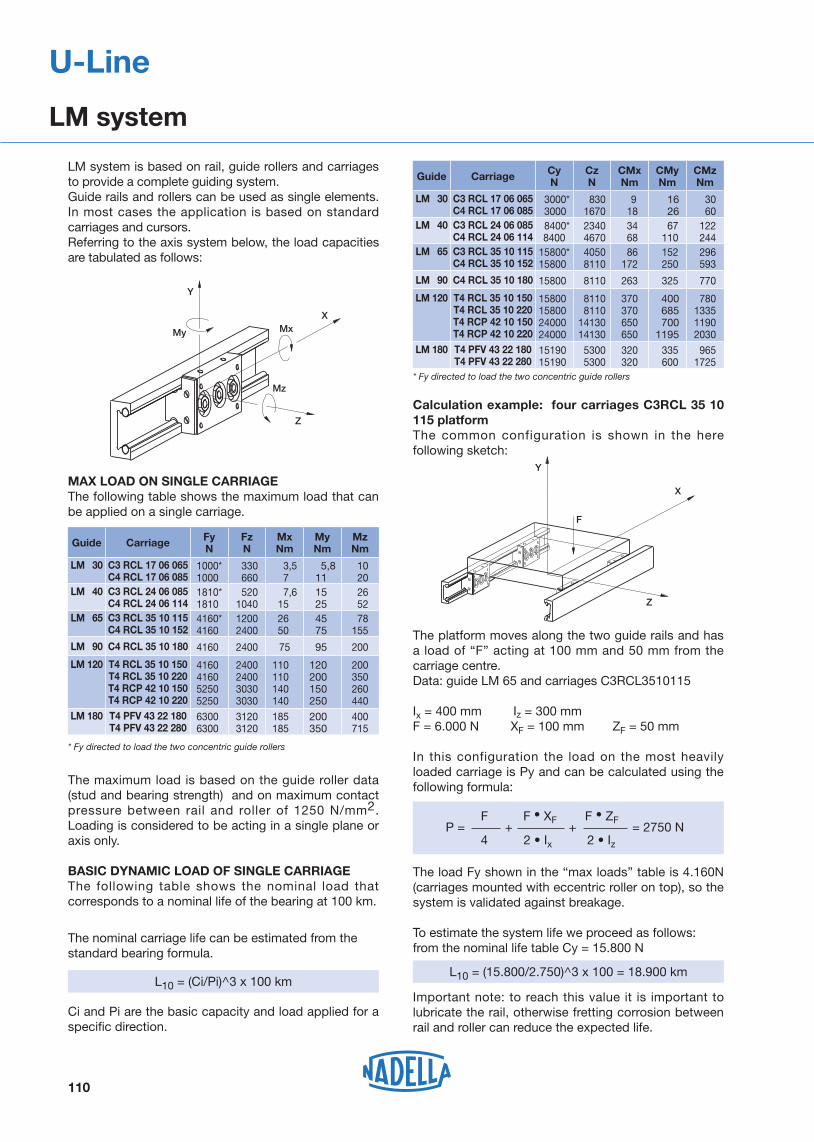
MAX LOAD ON SINGLE CARRIAGEThe following table shows the maximum load that can be applied on a single carriage.
Calculation example: four carriages C3RCL 35 10 115 platformThe common configuration is shown in the here following sketch:
The maximum load is based on the guide roller data (stud and bearing strength) and on maximum contact pressure between rail and roller of 1250 N/mm2. Loading is considered to be acting in a single plane or axis only.
BASIC DYNAMIC LOAD OF SINGLE CARRIAGEThe following table shows the nominal load that corresponds to a nominal life of the bearing at 100 km.
The nominal carriage life can be estimated from the standard bearing formula.
Ci and Pi are the basic capacity and load applied for a specific direction.
* Fy directed to load the two concentric guide rollers
Z
Y
X
Mz
MxMy
L10 = (Ci/Pi)^3 x 100 km
Z
Y
X
F
F F XF F ZF P = + + = 2750 N
x z
The platform moves along the two guide rails and has a load of “F” acting at 100 mm and 50 mm from the carriage centre.Data: guide LM 65 and carriages C3RCL3510115
Ix = 400 mm Iz = 300 mmF = 6.000 N XF = 100 mm ZF = 50 mm
In this configuration the load on the most heavily loaded carriage is Py and can be calculated using the following formula:
Important note: to reach this value it is important to lubricate the rail, otherwise fretting corrosion between rail and roller can reduce the expected life.
L10 = (15.800/2.750)^3 x 100 = 18.900 km
110
LM system is based on rail, guide rollers and carriages to provide a complete guiding system. Guide rails and rollers can be used as single elements. In most cases the application is based on standard carriages and cursors. Referring to the axis system below, the load capacities are tabulated as follows:
The load Fy shown in the “max loads” table is 4.160N (carriages mounted with eccentric roller on top), so the system is validated against breakage.
To estimate the system life we proceed as follows:from the nominal life table Cy = 15.800 N
U-Line
LM system
Guide Carriage MzNm
LM 30 C3 RCL 17 06 065C4 RCL 17 06 085
10 20
MyNm
5,8 11
MxNm
3,5 7
FzN
330 660
FyN
1000*1000
LM 40 C3 RCL 24 06 085C4 RCL 24 06 114
26 52
15 25
7,6 15
5201040
1810*1810
LM 65
LM 90
C3 RCL 35 10 115 C4 RCL 35 10 152
C4 RCL 35 10 180
78155
200
45 75
95
26 50
75
12002400
2400
4160*4160
4160
LM 180 T4 PFV 43 22 180T4 PFV 43 22 280
400715
200350
185185
31203120
63006300
LM 120 T4 RCL 35 10 150T4 RCL 35 10 220T4 RCP 42 10 150T4 RCP 42 10 220
200350260440
120200150250
110110140140
2400240030303030
4160416052505250
780133511902030
Guide Carriage CMzNm
LM 30 C3 RCL 17 06 065 C4 RCL 17 06 085
30 60
CMyNm
16 26
CMxNm
9 18
CzN
830 1670
CyN
3000* 3000
LM 40 C3 RCL 24 06 085 C4 RCL 24 06 114
122 244
67 110
34 68
2340 4670
8400* 8400
LM 65
LM 90
C3 RCL 35 10 115 C4 RCL 35 10 152
C4 RCL 35 10 180
296 593
770
152 250
325
86172
263
4050 8110
8110
15800*15800
15800
LM 180 T4 PFV 43 22 180T4 PFV 43 22 280
9651725
335 600
320320
5300 5300
1519015190
LM 120 T4 RCL 35 10 150T4 RCL 35 10 220T4 RCP 42 10 150T4 RCP 42 10 220
400 685 7001195
370370650650
8110 81101413014130
15800158002400024000

SystemsAuto-aligning systems are assembled with guide rollers RAL type on LM system carriages tables.The guide rollers RAL type allows axial displacement of the roller on the pin. An “O” ring retains the roller in position during the mounting.Auto-aligning systems compensate for opposite rail misalignment errors. They are useful for mounting inaccurately aligned structures or those structures subject to flexure.
C3RAL C4RAL T4RALIs used to compensate for Dx misalignment between opposite rails. The table or carriage with all guide rollers RAL/RALR type can move towards or away from the rail. Type RAL provides radial support only. Axial load, transverse to the direction of travel, is reacted by carriage type RCL on the opposite rail.
C3RYL C4RYL T4RYLRail misalignment Dy requires the ability for both carriages to rotate. The table or carriage RYL type, with guide rollers RCL/RCP in contact with a steel shaft of the LM rail and guide rollers RALR type in contact with the opposite shaft, allows carriage rotation ensuring at the same time the transverse direction control.The maximum Dy value is dependent on the distance between the rails and the tabulated maximum angle ‘α’ for that carriage.Note: RYL carriage axial load capability is lower than the same size RCL/RCP carriage.
1) See light load systems Nadella catalogue for table and carriage dimensions.2) Variations of dimension H exceeding ± s can compromise bearing axial moving and decrease
the roller limit load, Fr.
...RCL... ...RAL...
Dx
α
Dy
...RYL... ...RAL...
±α
H ± s
111
U-Line
Auto-aligning system
Carriage code (1)
Max transverse moving allowed by auto-aligning tables and carriages
LM 30C3RAL 17 06 065 C4RAL 17 06 085
� max(°)
S max(mm)
H nominal(mm)
Rail
1 0.8
C3RYL 17 06 065 C4RYL 17 06 085 1 –27.5
LM 40C3RAL 24 06 085 C4RAL 24 06 114 1 1
C3RYL 24 06 085 C4RYL 24 06 114 1 –35.7
LM 65
LM 90
C3RAL 35 10 115
–
C4RAL 35 10 152
C4RAL 35 10 180
1
1
1
1
0.3 1
C3RYL 35 10 115
–
C4RYL 35 10 152
C4RYL 35 10 180
1
1
–
–
58
60.5
LM 120
T4RAL 35 10 150 T4RAL 35 10 220
T4RYL 35 10 150 T4RYL 35 10 220 0.3 –58.5
0.75 1.5T4RAL 42 10 150 T4RAL 42 10 220
T4RYL 42 10 150 T4RYL 42 10 220 0.75 –65.5

LM 120
LM 90
LM 40LM 65
LM 30
112
U-Line
Guide rails LM
L(1)
max(mm)
6 000
Type
1 096.6
l1
Dimensions(mm)
B H
LM 40(4)
LM 30(4)
LM 120(4)
20
15.5
33.5
14
10.5
24
8
6
14
14
11
23.5
4.5
4.5
6.5
8
9.5
11
4
2.5
6
–
–
40
21
16
40
1.2
0.5
8.8
3
14.8 311.6
1.5
1.1
6
42
32
120
H1 H2 M D G g
–
–
–
Pa e
100
80
100
IB
29
21.5
92
dB
6
6
10
l
50
40
50
LM 65(4))
LM 90(4))
LM 180
32
35
45
23.5
26
32
13.5
20
22.5
22
29
26.5
6.5
9
10(3)
11
15
20.1(3)
6
0.5
6
–
38
136
32.5
26
–
8.8
16.4
54.9
160.2
53.3
4.1
4.7
13.1
65
90
180
–
–
12.5
100
100
–
42.5
65
120
10
10
22
50
50
–
Jx Jy
Weight (kg/m)
Moments of inertia(2)
(cm4)
6 000
6 000
6 000
6 000
6 000
Optional features- ground one end (R) - ground both ends ( RR ) - chromium plated shafts (CH)- stainless steel shafts (NX)
Example of standard designation : LM 40/1720 NF
See page 17 for standard codification
Hole layout- holes according to catalogue (SB)- finishes to drawing (NZ)- without holes (NF)
1) Longer rails are supplied in sections with ground butt joints and, on request, with pin connection2) Inertia value based on equivalent aluminium yield 70000 N/mm2
3) Slot for nut DIN 508 4) available with stainless steel shafts (suffix NX)
BD
GH2
H1H
dBlB
g
BD
GH2
H1H
dBlB
g
B
H2
H1H
dBlB
g
B
H2
H1H
dB lB
g
B
M
P
D(3) G(3)
a
H2H1
HdB
lB
g
D
l
L
a
e
l1
G
LM 180

Type
Type
RCPR 42.10
LM 180
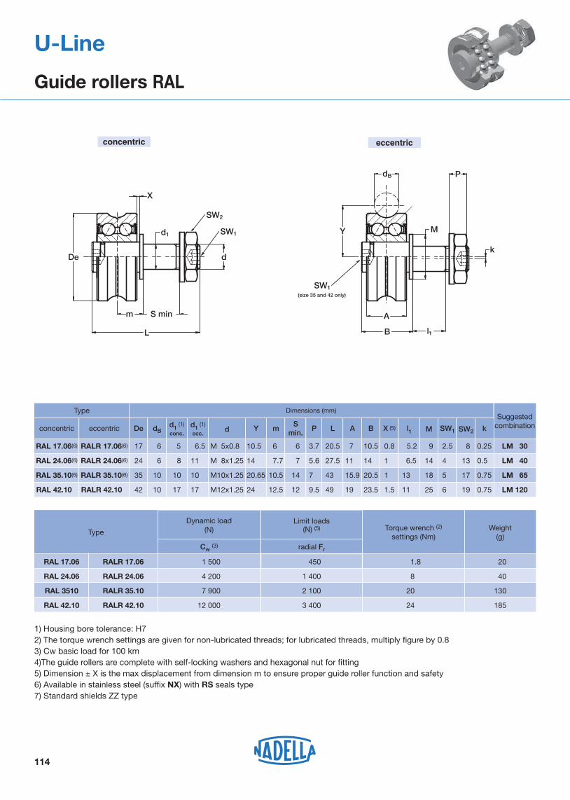
1) Housing bore tolerance: H72) The torque wrench settings are given for non-lubricated threads; for lubricated threads, multiply figure by 0.83) Available in stainless steel (suffix NX) with RS seals type4) Cw basic load for 100 km5) The guide rollers are complete with self-locking washers and hexagonal nut (DIN 439B) for fitting6) Pressure angle � for load calculation: 60°7) Standard shields ZZ type for RCL and RCP; NBR seals type RS for PFV
P
Y
B
A
SW1
l1
d1
k
De
m
L
dB
d
SW1
SW2
De
SW1
SW2
kSW1
P
d1
A
B
dB
Y
m
L
l1
d
S min.S
min.
MM
concentric concentric
RCL/RCP
eccentric eccentric
PFV
Suggestedcombination
Dimensions (mm)
LM 120
SW2
13
8
4
2.5
LM 40
LM 30
SW1M
14
9
6.5
5.2
l1
14.7
11
B
11
7
A
28.2
21
L
5.6
3.7
P
7
6
Smin.
7.7
6
14
10.5
Y m
11
6.5
M 8x1.25
M 5x0.8
d
6
6
dB
24
17
RCLR 24.06(3)
RCLR 17.06(3)
RCL 24.06(3)
RCL 17.06(3)
175 LM 65181320.515.943 71410.520.6510 M10x1.251035RCLR 35.10(3)RCL 35.10(3)
196251124.51950 9.51212.52417 M12x1.251042RCPR 42.10(3)RCP 42.10
19
k
0.5
0.25
0.75
0.75
15181227235212.513142912 M12x1.52243PFVR 43.22(3)PFV 43.22(3)
Deeccentricconcentric d1 (1)
ecc.
8
5
10
17
12
d1 (1)
conc.
RCL 17.06 RCLR 17.06
RCL 24.06 RCLR 24.06
RCL 35.10 RCLR 35.10
RCP 42.10
PFV 43.22 PFVR 43.22
Life coefficients
8
205
Weight(g)
Pa/Pr ≤ 0.37 Pa/Pr > 0.37
Torque wrench (2)
settings(Nm)
1.8
Dynamicload(N)
Cw(4) radial Fr axial Fa X Y X Y
1 500 530 260 1 1.37 0.5 2.73
Limit loads (N)
4 200 1 600 830 1 1.37 0.5 2.73
20 7 900 2 400 1 100 1 1.67 0.5 3.03
2412 000 4 300 1 160 1 1.17 0.5 2.53
26
20
40
130
185
7 600 3 150 780 1 4 1 4
113
U-Line
Guide rollers RCL, RCP, PFV
Suggestedcombination
LM 120
Type
1) Housing bore tolerance: H72) The torque wrench settings are given for non-lubricated threads; for lubricated threads, multiply figure by 0.83) Cw basic load for 100 km4)The guide rollers are complete with self-locking washers and hexagonal nut for fitting5) Dimension ± X is the max displacement from dimension m to ensure proper guide roller function and safety6) Available in stainless steel (suffix NX) with RS seals type7) Standard shields ZZ type
Dimensions (mm)
SW2
13
8
4
2.5
LM 40
LM 30
SW1M
14
9
6.5
5.2
l1
14
10.5
B
11
7
A
27.5
20.5
L
5.6
3.7
P
7
6
Smin.
7.7
6
14
10.5
Y m
11
6.5
M 8x1.25
M 5x0.8
d
6
6
dB
24
17
RALR 24.06(6)
RALR 17.06(6)
RAL 24.06(6)
RAL 17.06(6)
175 LM 65181320.515.94371410.520.6510 M10x1.251035RALR 35.10(6)RAL 35.10(6)
196251123.5
1
0.8
X (5)
1
1.519499.51212.52417 M12x1.251042RALR 42.10
k
0.5
0.25
0.75
0.75RAL 42.10
Deeccentricconcentric d1 (1)
ecc.
8
5
10
17
d1 (1)
conc.
concentric eccentric
Dynamic load(N) Weight
(g)
185
20
40
130
TypeTorque wrench (2)
settings (Nm)
RAL 17.06 RALR 17.06
Cw (3) radial Fr
1 500 450 1.8
Limit loads(N) (5)
RAL 24.06 RALR 24.06 4 200 1 400 8
RAL 3510 RALR 35.10 7 900 2 100 20
RAL 42.10 RALR 42.10 12 000 3 400 24
114
U-Line
Guide rollers RAL
De
m S min
L
X
Y
dB
k
M
A
l1
SW1
SW2
SW1(size 35 and 42 only)
d1
d
P
B

Di
De
A
B
Y
dB
(1)
115
U-Line
Guide wheels GLA
Limit loads(N) Weight
(g)
Dimensions(mm)
1) Tolerance of Diameter Di: +0 / -0.008 mm2) Cw basic load for 100 km3) Pressure angle � for load calculation: 60°
Type
Type
axial Coa
17015 400
dB
100
15GLA 47.10
11.9
7
A B
14
10.5
Y
8
5
Di (1)
6
6
24GLA 24.06 (4)
GLA 17.06 (4)
15.9
15.9
19
19.9
11.9
8
15.9
15.9
19
19.9
20.65
21.75
24
26.65
12
12
12
10
12
10
10
35
35
42
47
GLA 35.10 (4)
GLA 35.12
GLA 42.10
17
De
Life coefficients
Pa/Pr ≤ 0.37 Pa/Pr > 0.37
GLA 17.06
Dynamicload(N)
Cw (2) radial Cor X Y X Y
1 500 840 101 1.37 0.5 2.73
GLA 24.06 4 200 2 300 201 1.37 0.5 2.73
GLA 35.10 7 900 5 100 801 1.67 0.5 3.03
GLA 35.12 7 800 5 000 801 2.47 0.5 3.83
GLA 47.10 9 200 1 0.97 0.5 2.33
GLA 42.10 12 000 7 100
350
1 000
1 500
1 400
3 300
2 100 1 1.17 0.5 2.53
20.6 22.631.5201652GLA 52.16
230GLA 52.16 19 300 10 500 4 000 1 2.17 0.5 3.53
4) Available in stainless steel (suffix NX) with RS seals type 5) Standard shields ZZ type (GLA 52.16 with RS seals type)

Carriage C4RCL, C4RAL, C4RYL
116
U-Line
Carriage C3RCL, C3RAL, C3RYL
Type
Type
Suggestedcombina-
tions
Suggestedcombina-
tions
LM 65
LM 65
1) Dimensions in the table are correct also for carriages C4 RAL and C4 RYL2) Available with stainless steel guide rollers (suffix NX)
1) Dimensions in the table are correct also for carriages C3 RAL, C3 RYL 2) Available with stainless steel guide rollers (suffix NX)
G G
e
Iy
lxc
L
B
b
g
H1
u
k
H
H2
0.8
0.2
0.1 LM 30
LM 40
Weight (kg)
1
0.5
keubgGH2H1HIyIxBL
C3RCL 24 06 085
C3RCL 17 06 065
1.5C3RCL 35 10 115
Dimensions(mm)
35
24
60
7
5.5
14
6
4
10
c
6
6
10
8
6
10
M5
M4
M6
14
11
24
21.7
17
34.5
35.7
27.5
58
1
0.5
1.2
58
40
75
42
32
65
85
65
115
e
G G
B
c
b
Iy
Ix
L H
H2
k
g
u
H1
1
0.25
1.5
0.15 LM 30
LM 40
LM 90
Weight (kg)
1
2
0.5
keubgGH2H1HIyIxBL
C4RCL 24 06 114
C4RCL 35 10 180
C4RCL 17 06 085
1.5C4RCL 35 10 152
Dimensions(mm)
60
120
44
90
7
14
5.5
14
6
10
4
10
c
6
10
6
10
8
10
6
10
M5
M6
M4
M6
14
24
11
24
21.7
34.5
17
34.5
35.7
60.5
27.5
58
1
23.7
0.5
1.2
87
135
60
112.5
42
90
32
65
114
180
85
152

Lubricator LUBM
Iy
Ix
B
b
bL
GH
H2
H1
T4RCLT4RCP
H
b
b
G
B
=
=
= =L
H1
Iy
Ix
H2
T4PFV
117
U-Line
Carriage T4RCL, T4RCP, T4PFV, T4RAL, T4RYL
D
S A
ST
H
U
BE
LG
LUBM.. CD LUBM.. CDLUBM.. CSLUBM.. CS
2)
symmetry axisof the railC
LM 180
Type
LM 120
Iy
20
LM 120
Weight(kg)
Recommended pairing
Dimensions(mm)
T4RCL 35 10 150
T4RCL 35 10 220
T4RCP 42 10 150
T4RCP 42 10 220
T4PFV 43 22 180
T4PFV 43 22 280
1.6
LM 120
LM 120
LM 180
2.2
2
2.7
3.1
4.5
bGH2H1HIxBL
150
220
150
220
180
280
120
120
120
120
180
180
99
169
99
169
127
227
50.7
50.7
44
44
62
62
58.5
58.5
65.5
65.5
74
74
34.5
34.5
41.5
41.5
42
42
24
24
29
29
28
28
M8
M8
M8
M8
M10
M10
10
10
15
15
20
1) Dimensions valid also for T4RAL and T4RYL
Dimensions(mm)Type
LM 40
LM 30
LM 65
Suggested combinations with the railsL
C3 RCL C4 RCL
133
103
83
170
132
103
C
LUBM 040 CD/CS
LUBM 065 CD/CS
A
20.5
13.7
B
30
21.5
T
30
19
E
63
40
H
13
7
44.5
27
U
15
10
LUBM 030 9.5 16 1530 6.5 20.5 8
G
9
9
9
M4
M3
M2.5
S
1) The lubricator is supplied with the felt already lubricated. The lubricant has a mineral oil base - 2) One lubricator for packaging. Countersunk head screws for the mounting are already in the packaging - 3)The lubricator can be mounted on carriages RCL, RAL and RYL - (4) Optional felt without lubricant (D)
* Fy with effect on the two concentric rollers.
118
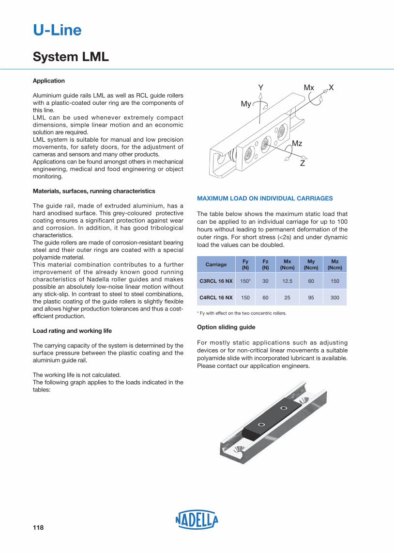
Application
Aluminium guide rails LML as well as RCL guide rollers with a plastic-coated outer ring are the components of this line.LML can be used whenever extremely compact dimensions, simple linear motion and an economic solution are required. LML system is suitable for manual and low precision movements, for safety doors, for the adjustment of cameras and sensors and many other products.Applications can be found amongst others in mechanical engineering, medical and food engineering or object monitoring.
Materials, surfaces, running characteristics
The guide rail, made of extruded aluminium, has a hard anodised surface. This grey-coloured protective coating ensures a significant protection against wear and corrosion. In addition, it has good tribological characteristics. The guide rollers are made of corrosion-resistant bearing steel and their outer rings are coated with a special polyamide material.This material combination contributes to a further improvement of the already known good running characteristics of Nadella roller guides and makes possible an absolutely low-noise linear motion without any stick-slip. In contrast to steel to steel combinations, the plastic coating of the guide rollers is slightly flexible and allows higher production tolerances and thus a cost-efficient production.
Load rating and working life
The carrying capacity of the system is determined by the surface pressure between the plastic coating and the aluminium guide rail.
The working life is not calculated.The following graph applies to the loads indicated in the tables:
Option sliding guide
For mostly static applications such as adjusting devices or for non-critical linear movements a suitable polyamide slide with incorporated lubricant is available.Please contact our application engineers.
MAXIMUM LOAD ON INDIVIDUAL CARRIAGES
The table below shows the maximum static load that can be applied to an individual carriage for up to 100 hours without leading to permanent deformation of the outer rings. For short stress (<2s) and under dynamic load the values can be doubled.
U-Line
System LML
CarriageFy(N)
Fz(N)
Mx(Ncm)
My (Ncm)
Mz (Ncm)
C3RCL 16 NX 150* 30 12.5 60 150
C4RCL 16 NX 150 60 25 95 300
My
Mx
Mz
Y X
Z
Carriage C3RCL 16 NX
Carriage C4RCL 16 NX
119
U-Line
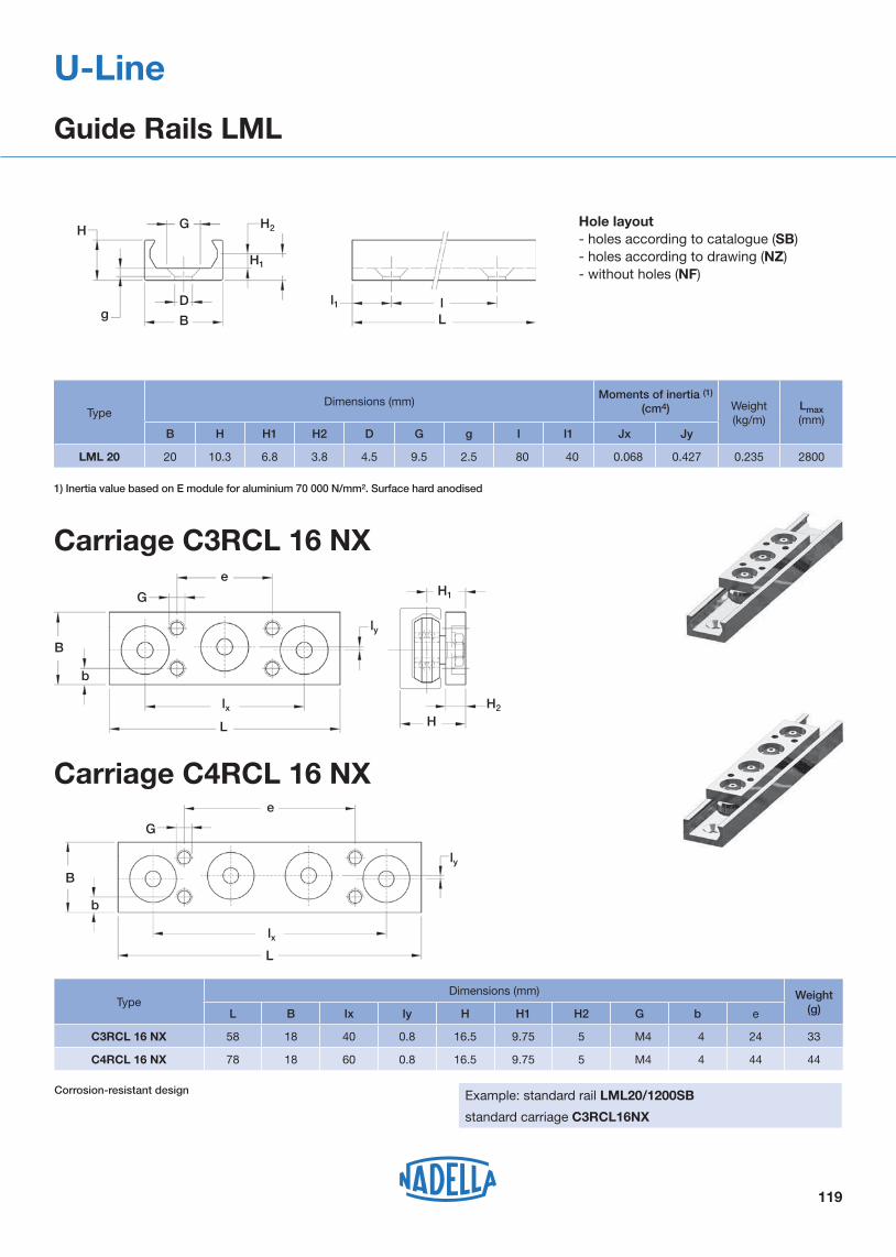
Guide Rails LML
1) Inertia value based on E module for aluminium 70 000 N/mm². Surface hard anodised
Corrosion-resistant design
Hole layout- holes according to catalogue (SB) - holes according to drawing (NZ) - without holes (NF)
TypeDimensions (mm)
Moments of inertia (1) (cm4) Weight
(kg/m)Lmax(mm)
B H H1 H2 D G g I I1 Jx Jy
LML 20 20 10.3 6.8 3.8 4.5 9.5 2.5 80 40 0.068 0.427 0.235 2800
TypeDimensions (mm) Weight
(g)L B Ix Iy H H1 H2 G b e
C3RCL 16 NX 58 18 40 0.8 16.5 9.75 5 M4 4 24 33
C4RCL 16 NX 78 18 60 0.8 16.5 9.75 5 M4 4 44 44
Example: standard rail LML20/1200SB
standard carriage C3RCL16NX
B
D
G H2
H1
H
l1 lLg
B
L
e
G H1
lx
b
HH2
ly
B
L
e
G
lx
b
ly
120
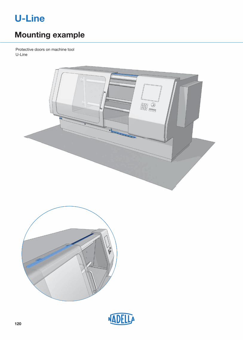
U-Line
Mounting example
Protective doors on machine toolU-Line


