56
U Use r’s Gu ide (ver sion 2 2)
U
User’s Guide (version 22)
2
TABLE OF CONTENTS
FEATURES ___________________________________________________________________ 4
Cyclebox Architecture __________________________________________________________ 5
Cyclebox Front Panel __________________________________________________________ 7
LAG and LEAD Outputs _________________________________________________________ 8
Oscillator Pitch Control ________________________________________________________ 9
OSC1 and OSC2 Waveform Select _______________________________________________ 11
OSCILLATOR WAVEFORMS _________________________________________________________ 12
OSC1 Wavetable Mode _______________________________________________________ 14
Wavetable Bank 1 – Random Pulses __________________________________________________ 15
Wavetable Bank 2 – Truncated Sawtooth _____________________________________________ 15
Wavetable Bank 3 – Pulses (mirrored) ________________________________________________ 16
Wavetable Bank 4 – Bipolar Pulses ___________________________________________________ 16
Wavetable Bank 5 – Sawtooth Filter Sweep (mirrored) __________________________________ 17
Wavetable Bank 6 – Sawtooth Filter Sweep ___________________________________________ 17
Wavetable Bank 7 – Vowels (mirrored) _______________________________________________ 18
Wavetable Bank 8 – Vowels ________________________________________________________ 18
Output Modes – Waveform Combination _________________________________________ 19
MODE 0000 _____________________________________________________________________ 20
MODE 0001 _____________________________________________________________________ 21
MODE 0010 _____________________________________________________________________ 24
MODE 0011 _____________________________________________________________________ 26
MODE 0100 _____________________________________________________________________ 27
MODE 0101 _____________________________________________________________________ 28
MODE 0110 _____________________________________________________________________ 30
MODE 0111 _____________________________________________________________________ 31
MODE 1000 _____________________________________________________________________ 33
MODE 1001 _____________________________________________________________________ 34

3
MODE 1010 _____________________________________________________________________ 35
MODE 1011 _____________________________________________________________________ 36
MODE 1100 _____________________________________________________________________ 37
MODE 1101 _____________________________________________________________________ 38
MODE 1110 _____________________________________________________________________ 39
MODE 1111 _____________________________________________________________________ 40
Output Gain and Waveform Folding _____________________________________________ 41
Internal Frequency Modulation _________________________________________________ 42
OSC2 Phase Control __________________________________________________________ 43
OSC2/OSC1 Ratio ____________________________________________________________ 44
Oscillator Sync ______________________________________________________________ 45
Mega Mode ________________________________________________________________ 46
OCTAVE/Tuning/LFO Display ___________________________________________________ 47
Tuning Scale Adjustment ______________________________________________________ 48
Module Expansion (optional!) __________________________________________________ 49
Power Supply Connection _____________________________________________________ 53
Output Offset Adjustment _____________________________________________________ 54
Electrical and Mechanical Specifications__________________________________________ 55

4
FEATURES Wide 22‐octave frequency range (48KHz down to one cycle every 80 seconds) 3 oscillators: main ‐ OSC1, secondary – OSC2, sub/sync‐oscillator – OSC3 (triangle or square wave at half the frequency of OSC1) 8 different waveforms for OSC1 and OSC2 with smooth morphing:
o Sine, triangle, sine‐pulse1, square, saw, square‐saw, sine‐pulse2, random
8 additional externally selectable wavetable shape sets for OSC1 : o random pulses, truncated saw, bipolar pulse, mirrored
bipolar pulse, resonant saw sweep, mirrored resonant saw sweep, vowels, mirrored vowels
MEGA mode for OSC1 which stacks 8 detuned versions of the OSC1 waveform 16 different nonlinear waveform combinations High‐Quality “through‐zero” Internal Frequency Modulation of OSC1 by OSC2 Two Quadrature outputs (i.e. separated by 90 degrees in phase) Externally controlled output asymmetric waveform folding Internal and External oscillator sync External control of internal FM level, OSC2 phase and OSC2 ratio LED display of pitch octave (C‐22 to C9) and LFO output levels 256x oversampled digital sound generation with low aliasing noise 96KHz output sampling rate Expandable to give additional wave shapes, one‐shot, non‐through zero FM, octave shift, lfo mode, percussive and reverse sync modes
5
Cyclebox Architecture

6
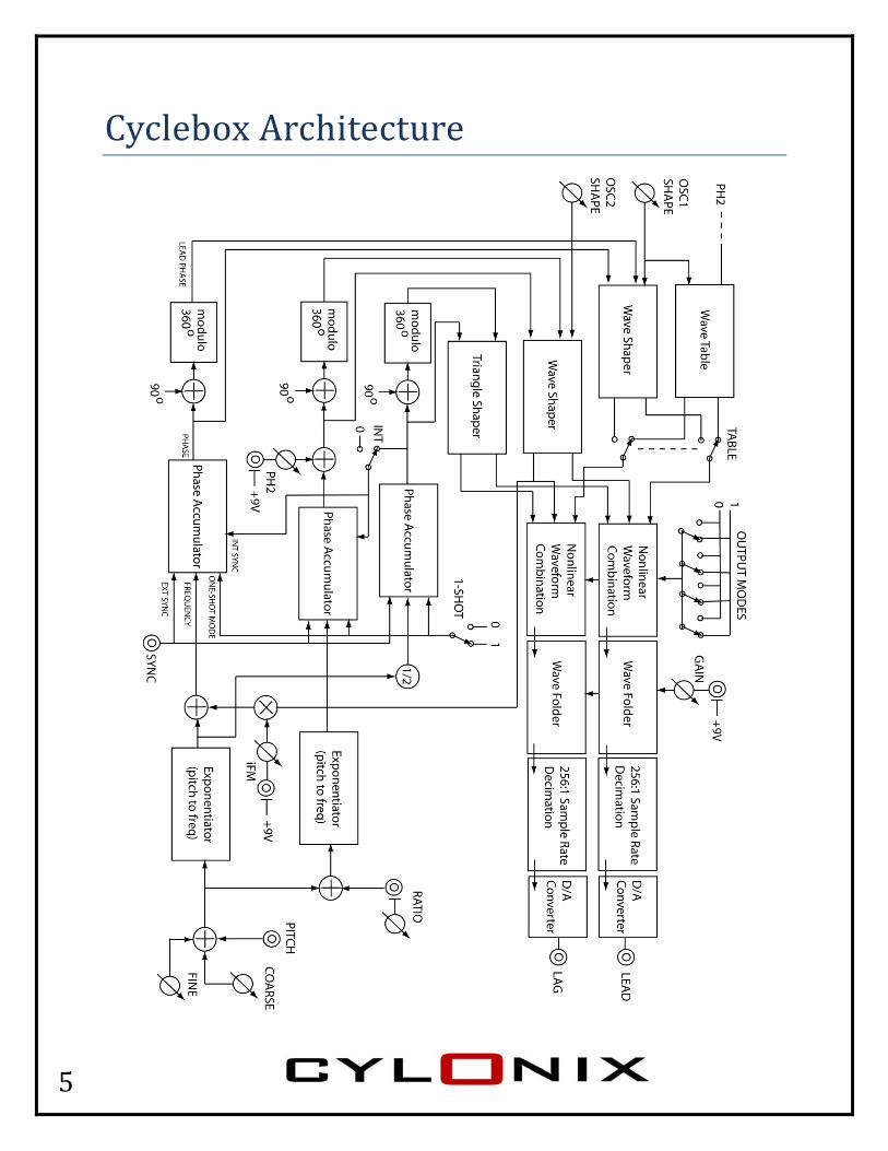
The Cyclebox system consists of three oscillators (OSC1, OSC2, and OSC3) whose outputs are combined nonlinearly. There are 16 different combination modes available, selected through a set of 4 toggle switches. The output of the combination unit is passed through a gain stage and an asymmetric wave‐folder and then to the module’s output jacks. The gain is set by the GAIN input and control.
Each oscillator has two outputs, nominally 90 degrees apart in phase. OSC1 and OSC2 have multiple possible waveshapes, selected by the SHAPE controls. OSC3 outputs either a triangle or square waveform. OSC1 also has access to a set of waveshapes stored in a wavetable.
The overall pitch of the oscillators is set by the 1V/octave PITCH input as well as by the COARSE and FINE pitch controls. The pitch of OSC2 is offset from the main pitch by an amount determined by the RATIO input and control. The pitch of OSC3 is fixed at one octave lower than the main pitch. The frequency of OSC1 can be modulated by the output of OSC2. The level of this modulation is set by the iFM input and control. The phase of OSC2 can be shifted using the PH2 input and control.
The start of the oscillator cycles for OSC1 and OSC2 can be synchronized either to the start of an OSC3 cycle (if the INT switch is in the up position) or to the reception of a suitably strong positive going pulse at the SYNC input.

7
Cyclebox Front Panel
The function and operation of the front panel jacks, knobs, and switches are described in the following sections of this user’s guide.

8
LAG
the samshiftedthe oscLEAD ofigure
[Please nsoundcarslanting
G and
me frequd replicas cillators boutputs wbelow.
note that allrd, which reof the flat p
LEAD
ency, theof each obeing comwill not ha
l waveform iemoves low fparts of the s
D OutpThThthcoLAcowadeshwadewhof
e LAG andother, as mbined haave the sa
images in thfrequency cosquare‐wave
putshe Cyclebhese outpe output ombiner tAG outputombinatioaveformserived frohifted versaveformsegrees, exhere the f the oscild LEAD oushown inave differame shap
his documenomponents.es) which is
ox moduputs are oof the nohrough tt is deriveon of the s, while thom the cosions of ts. The phaxcept in ophase shlators beutputs wiln the left rent frequpe, as sho
nt were capt This causesactually no
le has twobtained bonlinear whe wave‐ed from t3 oscillathe LEAD oombinatiohe 3 osciase shift ioutput moift is adjuing combll appear hand figuuencies, twn in the
tured with as a slight drot present in
wo outputby passinwaveform‐folder. Thhe or output is on of phasllator s fixed atode 0001ustable. Ifbined havas time‐ure belowthe LAG ae right ha
an AC‐coupleooping (e.g. the outputs
s. g
m he
se‐
t 90 1, f all ve
w. If and nd
ed a s.]

9
Osci
range o
The pitfrequefrom thRatio c
illator
of 1 semi
tch of oscency modhat of osccontrol.
r Pitc
tone.
cillator 3 ulation ocillator 1
ch ConThknth
Thchin Vora
Thofanpr
is always f oscillatoby an am
ntrolhe Pitch innobs labee pitch of
he Pitch inhange in pthe inputolts to +6nge of 16
he Coarseffset to thnd 6 octavrovides an
one half or 1). Themount set
nput, in cled Coarsf the osci
nput prodpitch for et. It has aVolts, giv6 octaves
e pitch cohe Pitch inves. The Fn addition
that of oe pitch of by the Ra
ombinatise and Finillators.
duces a oevery 1 Van input rving a tot.
ntrol pronput of beFine pitchnal offset
oscillator 1oscillatoratio input
ion with tne, adjust
ne octaveolt changange of ‐tal pitch
vides an etween 0h control t over a
1 (excludr 2 is offst or the
the ts
e ge 10
0
ing et

10
The usable range of the pitch variation for the oscillators is about 22 octaves, as the oscillator shuts off at a frequency of 48 KHz.
The following table shows the approximate oscillator frequency or period for various levels of the pitch input and settings of the COARSE control (assumes that the FINE knob is at 12 o’clock). The COARSE knob shifts the pitch over about a 6.5 octave range. Pitch input voltage COARSE control
‐10V ‐5V 0V +5V +10V
CCW 80 sec 0.4 Hz 12.8 Hz 400 Hz 1.28 KHz
mid 8 sec 4 Hz 128 Hz 4 KHz 12.8 KHz
CW 0.8 sec 40 Hz 1.28 KHz 40 KHz off
The usual mode of operation will be with a PITCH input of between 0 and 5 volts (which is the range for most MIDI‐CV converters). Thus, in this case the range of frequencies will be from about 12 Hz to 40 KHz.
To use the Cyclebox as an LFO you should input a negative voltage into the pitch input. An input of ‐10V will produce oscillator periods from about a second to over 80 seconds over the full range of the COARSE control, which should be sufficient for most LFO applications. Or you could set the COARSE knob to its midrange, in which case the period ranges from 1/128th of a second to 8 seconds as the pitch input varies from 0 down to ‐10 volts.

11
OSC
using arandom
These
The shshapes
C1 and
a pseudo‐m level on
waveform
ape knobs, permitt
d OSC
‐random n each cy
ms are de
b providesting addit
C2 WaThthea
Eawath
Thfro
SINSQSIN
Thnumber gycle. This
epicted on
s a smoottional inte
aveforhe knobs e shape oach of the
ach oscillaaveformsese contr
he wavefoom the bo
NUSOID, QUARE, SNE‐PULSE
he RANDOgeneratolevel is he
n the follo
th morphermediat
rm Selabeled Oof the wae two mai
ator has 8s availablerols.
orms are,ottom lef
TRIANGLAWTOOTE2, and R
OM waver to prodeld const
owing pa
hing betwe shapes
lect OSC1 and aveforms in oscillat
8 differene for sele
, going cloft:
LE, SINE‐PTH, SQUARANDOM
eforms aruce a diffant durin
ge.
ween succ.
OSC2 seloutput btors.
nt ction by
ockwise
PULSE1, ARE‐SAW
e createdferent ng the cyc
cessive
lect by
W,
d
cle.
12
O
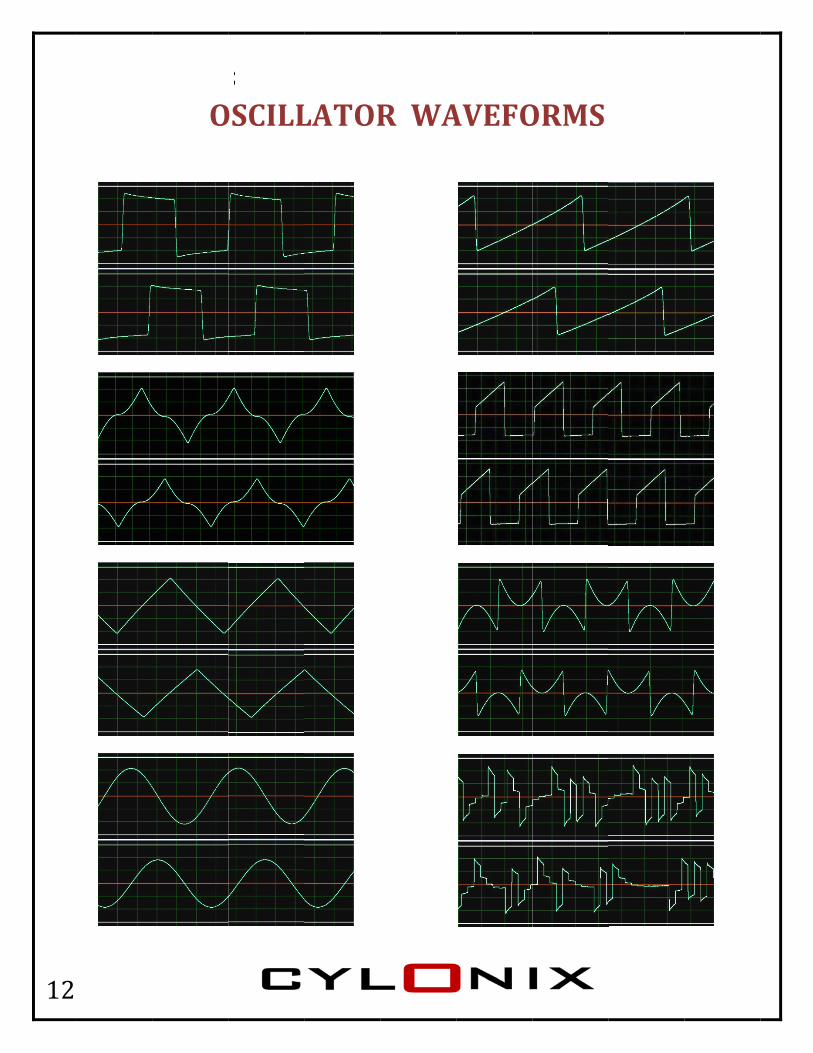
OSCILLLATOR
R WA
AVEFO
ORMS
13
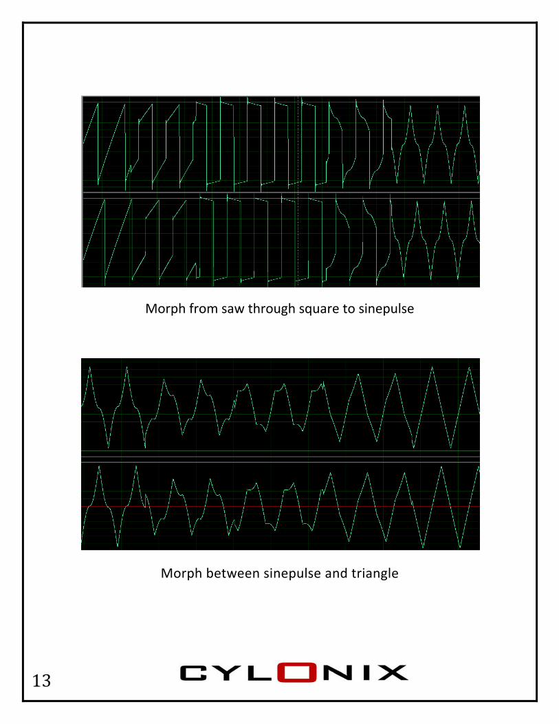
Morph from saw through square to sinepulse
Morph between sinepulse and triangle

14
OSC
using tscannior envescannislight j
The indvariatiodifferefew pacontro
C1 Wa
the PH2 inng of a welope). Thng of the umps bet
dividual wons on a ent wavefages, startl to fully
avetab
nput and wavetable he PH2 siwavetabtween ad
wavetablesingle typforms. Thting fromclockwise
ble MoWpofroThseWindsawaphbewa
Thcontrol. Tbank usiignal is noble bank isdjacent w
e banks ape of wave bank w
m fully coue.
ode When the Tosition, thom wavethere are 8elected usWithin eacdividual omples eaavetable hase valueetween saaveforms
he one‐cyThe PH2 ng an extot interpos sometimaveforms
re intendveform, rawaveformsunter‐cloc
TABLE swhe OSC1 wtables sto8 banks osing the Oh bank thone‐cycleach. The sare indexe and theamples. Ts to appea
ycle waveinput thuternal sigolated, mmes noisys.
ded to proather thas are descckwise on
witch is in waveformored in mf wavetabOSC1 SHAhere are 1e waveforsamples sxed by there is no iThis causear steppe
forms areus allows nal (sucheaning thy, as there
ovide swen as collecribed onn the OSC
the up ms are takmemory. bles, APE contro128 rms with 2stored in te OSC1 nterpolates the ed.
e selectedthe as an LFOhat the e are can
eepable ections ofn the nextC1 SHAPE
ken
ol.
256 the
tion
d
O
be
f t
15
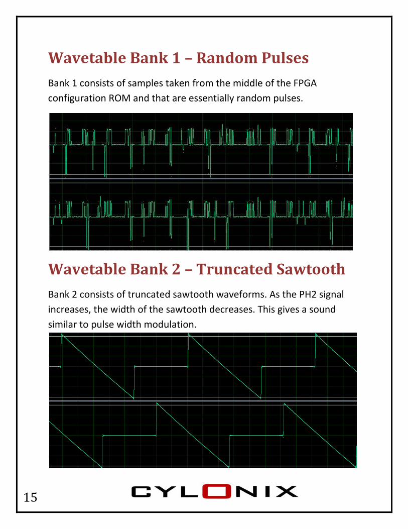
Wavetable Bank 1 – Random Pulses Bank 1 consists of samples taken from the middle of the FPGA configuration ROM and that are essentially random pulses.
Wavetable Bank 2 – Truncated Sawtooth Bank 2 consists of truncated sawtooth waveforms. As the PH2 signal increases, the width of the sawtooth decreases. This gives a sound similar to pulse width modulation.
16
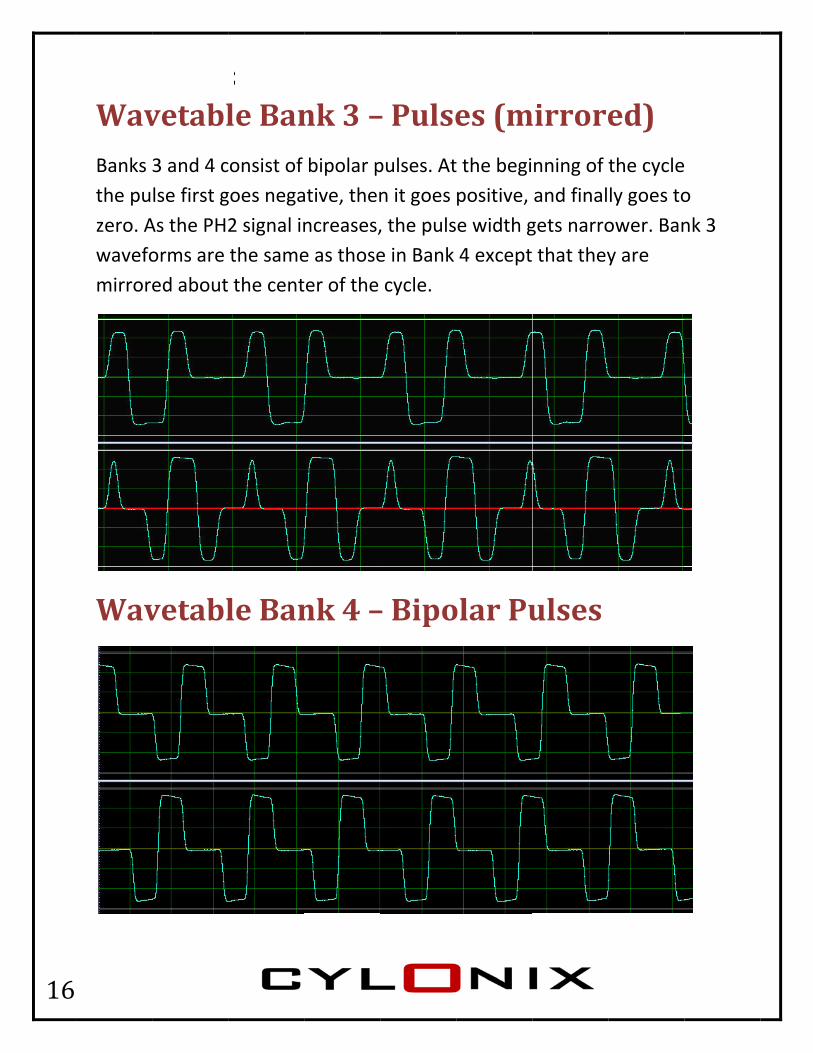
WavBanks the puzero. Awavefomirror
Wav
vetabl3 and 4 clse first gAs the PHorms are ed about
vetabl
le Banconsist of goes nega2 signal inthe same the cent
le Ban
nk 3 –bipolar p
ative, thenncreases,e as thoseter of the
nk 4 –
– Pulsepulses. Atn it goes , the pulse in Bank cycle.
– Bipo
es (mt the begipositive, e width g4 except
olar Pu
mirrorenning of and finalgets narro that they
ulses
ed) the cyclely goes toower. Bany are
o nk 3

17
Wavetable Bank 5 – Sawtooth Filter Sweep (mirrored) Banks 5 and 6 consist of sawtooth waves passed through a resonant lowpass filter. As the PH2 signal increases, the resonance frequency increases. Bank 5 waveforms are the same as those in Bank 6 except that they are mirrored about the center of the cycle.
Wavetable Bank 6 – Sawtooth Filter Sweep

18
Wavetable Bank 7 – Vowels (mirrored) Banks 7 and 8 consist of different vowel waveforms. Bank 7 waveforms are the same as those in Bank 8 except that they are mirrored about the center of the cycle.
Wavetable Bank 8 – Vowels

19
Outp
digital digital
Some onecessthey m
put M
in naturewords.
of the comsary to unmake!
Modes
e and the
mbinationderstand
s – WaOndisnowa
Thcous“othon
Socoat
wavefor
n operatid how the
aveforne of the stinctive onlinear caveforms
here are 1ombinatiosing the tooutput moought of ne packag
ome of thombining the bit‐lems are re
ions are rey work to
rm Cokeys in gCylonix ccombinats.
16 differeon modesoggle swiodes”. Thas 16 diffge!
e combinthe OSC1evel. The epresente
rather arco appreci
ombingeneratingcyclebox sion of the
ent outpus availabletches labhe Cycleboferent sy
nation mo1, 2, and 3Cycleboxed interna
cane, but iate the s
nationg the sound is te oscillato
t wavefoe, selectabeled ox can benthesizer
odes invo3 wavefox module ally by 24
it is not sounds th
n
the or
rm able
e rs in
olve rms is
4‐bit
at

20
MODE 0000
OSC 1
In this mode the waveform produced by OSC1 is passed directly to the output of the waveform combiner.
Use this mode to get the basic waveshapes (sine, triangle, sinepulse1, square, sawtooth, square‐saw, sinepulse2, random, and wavetable waveforms).
This mode is good for obtaining FM sounds (try setting both the waveforms of OSC1 and OSC2 to sine and playing with the RATIO and IFM controls).

21
MODE 0001
OSC 2
In this mode the waveform produced by OSC2 is passed directly to the output of the waveform combiner.
This mode can also be used to get basic waveshapes as in mode 0000. The MEGA‐waves are not available.
This mode can be used to obtain FM sounds with external modulation by using the RATIO input. This modulation is of (much) lower quality than produced by the internal modulation path of OSC1 in mode 0000. The sampling rate is much lower and the bit width is lower. The modulation is also exponential rather than linear.
In this mode the phase shift between the LAG and LEAD outputs is not fixed at 90 degrees, but is adjustable using the PH2 input and control. A PH2 input of 0 Volts gives 0 degrees phase difference, about +4 Volts gives 180 degrees and about +8 Volts gives +360 degrees. Negative voltages produce negative phase differences.

22
Feedinmodul
In addithe LAGoutputfigures
ng an LFO ation of t
ition, in tG output t wavefors below.
or oscillathe outpu
his modewhich is rms and e
ator signaut wavefo
e the iFM fed back even prod
al into theorm as sh
input is uto the phduce chao
e PH2 inpown in th
used conthase inpuotic outpu
put can givhe figure
trol the aut. This cauts, as sh
ve a phasbelow.
mount ofan bend town in th
se
f he he

23
In this an addwavefowavesh(i.e. in waveshselectiShape waveshShape is an ofwhen tshape passes
The resare a to
MODE thditional wolding. Thhaper. Wthe SINE haper is ang a SINEcontrol ishaper is ais betweeffset SINEthe OSC1is applied the nega
sult of thotal of 32
he SHAPEwaveshapehere are f
When the Oor TRIANa SAWTOE for OSC2s betweea TRIANGen ½ andE. This pro shape cod. This sqative part
is additio2 basic wa
control fer that is four possOSC1 ShaNGLE posiOTH. This2 gives a n ¼ and ½LE shape ¾ a turnovides a sontrol is fuares off t unchang
onal waveaveforms
for OSC1 applied tible shapape controition) thes does noSINE on t½ a turn c. This fold clockwissomewhafrom ¾ tof the positged.
eshaping s rather th
is used toto the outes for thiol is fully n the shaot alter ththe outpuclockwiseds the ouse the addat smootho fully cloctive part
is that in han just 8
o select thtput of ths additiocounter‐ape of thehe outputut. When e, the addtput. Whditional wh folding.ckwise, aof the wa
MODE 008 as in MO
he shapehe nal ‐clockwisee additiont at all, sothe OSC1
ditional hen the Owaveshap. Finally, square‐save and
001 thereODE 0000
of
e nal o 1
SC1 er
saw
e 0.

24
MODE 0010
OSC1, OSC 2
In this mode the waveform produced by OSC1 is passed directly to the LEAD channel of the wave folder and the output of OSC2 is passed to the LAG channel.
In this way the Cyclebox becomes two independent oscillators.
The pitch of OSC1 is controlled by the PITCH input as usual, but the pitch of OSC2 is controlled by the RATIO input or the RATIO control if nothing is plugged into the RATIO jack. Both inputs have a 1V/octave response. The COARSE and FINE controls affect both oscillators by the same amount. Thus, if the same signal is input to the PITCH and RATIO inputs the pitches of OSC1 and OSC2 will be the same (in practice they will be slightly different due to offsets in the two separate A/D converter channels used for the two inputs).
The wavefolder works as usual, as do the SYNC and the internal FM of OSC1 by OSC2.
In this mode the PH2 control and input also adjust the amount of OSC1 output that modulates the phase of OSC2. By combining the usual FM of OSC1 by OSC2 with the phase modulation of OSC2 by OSC1 interesting and sometimes chaotic sounds can be created.

25
Mode 0010 combination of an OSC1 saw and a fixed frequency OSC2 saw with a little bit of FM and PM feedback
Mode 0010 combination of an OSC1 triangle and a fixed frequency OSC2 triangle with heavy FM and PM feedback

26
MODE 0011
OSC1 + (OSC 2+OSC3)/2
In this (linear) combination mode the OSC1 waveform is added to half‐amplitude OSC2 and OSC3 waveforms. The OSC3 waveform is set to squarewave.
This can produce some rich classical synthesizer sounds, for example when OSC1 is set to hex‐saw and OSC2 to saw at an octave above.
Mode 0011 combination of an OSC1 hex‐square and an OSC2 saw

27
MODE 0100
MINIMUM(OSC1, OSC 2)
In this mode the output is the minimum of the OSC1 and OSC2 waveforms.
Mode 0100 combination of an OSC1 sawtooth and an OSC2 sinusoid with three times the frequency of OSC1

28
MODE 0101
Bitwise C‐Element of OSC1 and OSC2 with OSC2 Phase Perturbation
In this mode the output is obtained by applying a Muller C‐Element operation bitwise on the OSC1 and OSC2 waveform values. A C‐Element is like an AND gate for bit transitions – the result goes high only when both input bits are high, and goes low only when both input bits are low. Otherwise (i.e. when the input bits have different values) the output is held constant at whatever its current value is. This in itself provides a mildly interesting, sometimes glitchy, waveform but to spice things up a bit, the output of the C‐Element operation is bitwise ANDed with the PH2 input/control signal. The result of this AND operation is then fed back into the OSC2 phase modulation input. The result is that there is a perturbation of OSC2’s phase whenever there is a transition (either from high to low or from low to high) of any of the bits in the C‐Element output. This magically produces wild fluctuations in the output signal. Turning up the iFM control makes things even more wooly and wacky.
This mode is especially useful as an LFO in generating rather chaotic yet somewhat repetitive signals.
29
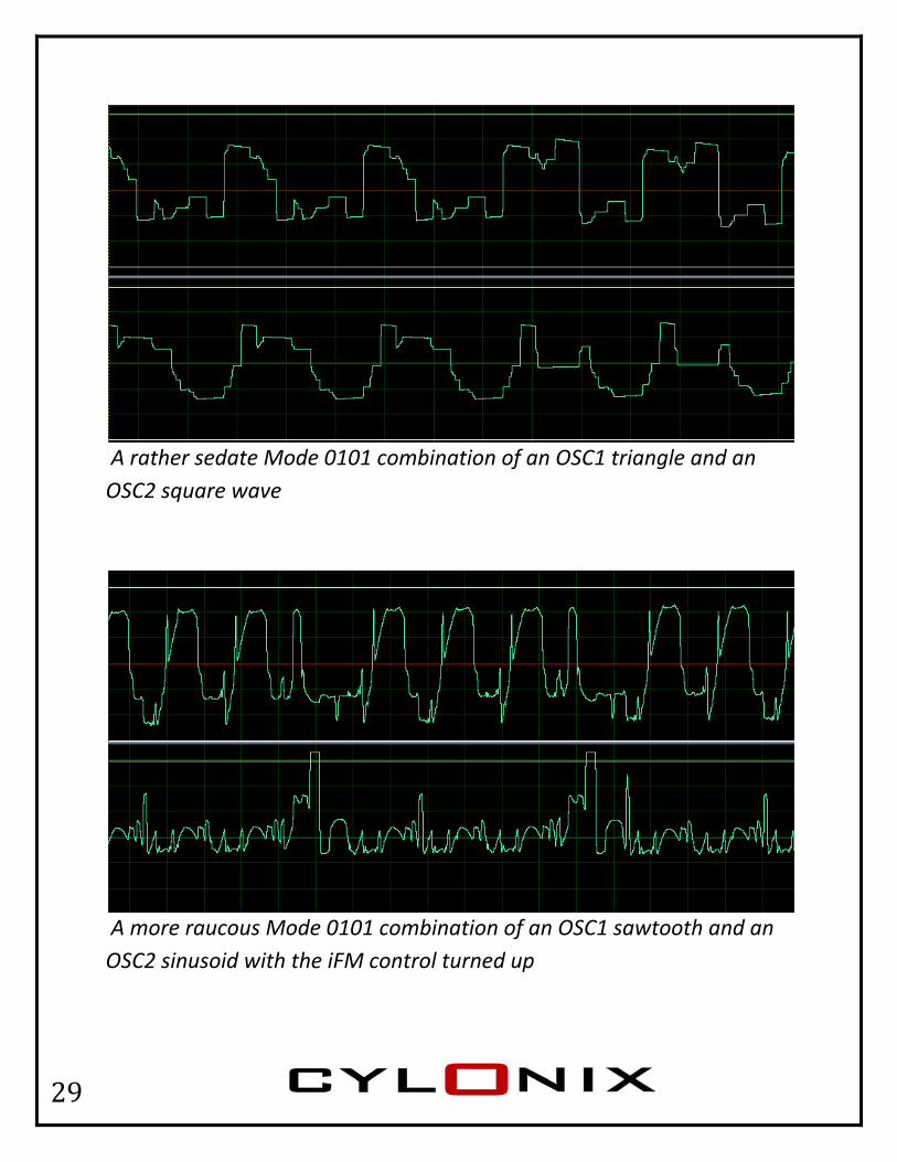
A rather sedate Mode 0101 combination of an OSC1 triangle and an OSC2 square wave
A more raucous Mode 0101 combination of an OSC1 sawtooth and an OSC2 sinusoid with the iFM control turned up

30
MODE 0110
[OSC1(23) OSC2(22) OSC3(21) OSC2(20) OSC1(19)…OSC1(0)]
In this mode the most‐significant four bits of the OSC1, OSC2, and OSC3 waveforms are interleaved, bit‐by‐bit, to produce the output value. The most‐significant‐bit (bit 23) of the output is taken from the most‐significant‐bit of OSC1, bit 22 of the output is taken from bit 22 of OSC2, bit 21 of the output is taken from bit 21 of OSC3, bit 20 of the output is taken from bit 20 of OSC2, and the remaining bits (19 down to 0) are taken from OSC1.
Mode 1011 combination of an OSC1 sinusoid and an OSC2 sawtooth
31
MODE 0111
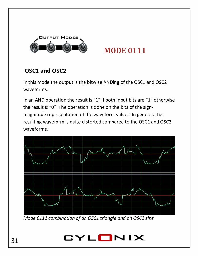
OSC1 and OSC2
In this mode the output is the bitwise ANDing of the OSC1 and OSC2 waveforms.
In an AND operation the result is “1” if both input bits are “1” otherwise the result is “0”. The operation is done on the bits of the sign‐magnitude representation of the waveform values. In general, the resulting waveform is quite distorted compared to the OSC1 and OSC2 waveforms.
Mode 0111 combination of an OSC1 triangle and an OSC2 sine

32
Setting one of the waveforms to square produces a form of gating. The maximum level of the square has all bits equal to one save for the most significant bit, which is zero. The AND operation passes the other signal through unchanged, but sets the most significant bit to zero. For a positive signal there is no effect, but for a negative signal the effect is to shift the signal up into the positive range. The minimum level of the square is all zeros except for the most significant bit, which is one. In this case the AND operation sets any positive signal to zero and sets any negative signal to the most negative value. This effect is demonstrated in the figure below, which has OSC2 set to a square wave, and OSC1 set to sawtooth.
Mode 0111 combination of an OSC1 saw and an OSC2 square

33
MODE 1000
OSC1 xor OSC 2
In this mode the OSC1 and OSC2 waveforms are XOR’ed, bit‐by‐bit.
The n^th bit output by the XOR operation is “0” whenever the n^th bits of OSC1 and OSC2 are the same (i.e. both either “0” or “1”), otherwise the bit is set to “1”. The operations are done on the 2’s‐complement representation of the signal values. Bit‐wise xor operations cause a “bit‐rot” effect on the waveform, which adds high frequency sheen to the sound.
Mode 1100 combination of an OSC1 sawtooth and an OSC2 sinusoid
34
MODE 1001
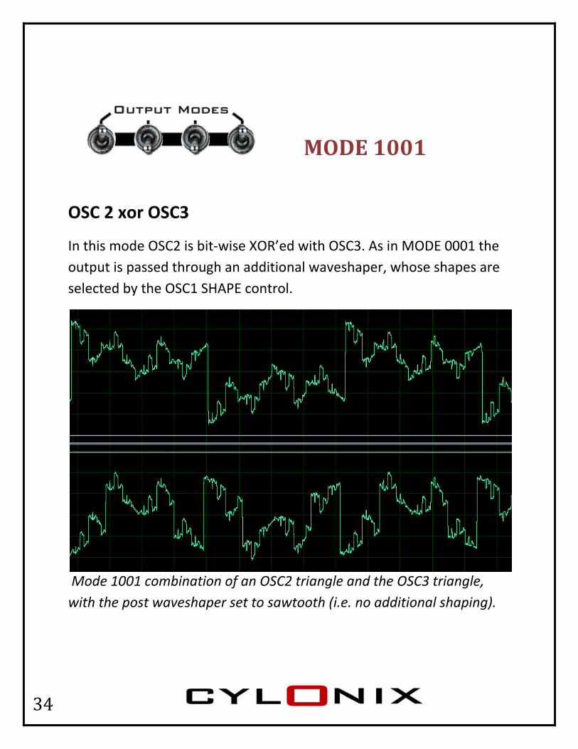
OSC 2 xor OSC3
In this mode OSC2 is bit‐wise XOR’ed with OSC3. As in MODE 0001 the output is passed through an additional waveshaper, whose shapes are selected by the OSC1 SHAPE control.
Mode 1001 combination of an OSC2 triangle and the OSC3 triangle, with the post waveshaper set to sawtooth (i.e. no additional shaping).

35
MODE 1010
OSC 1 xor OSC2 offset
In this mode OSC1 and OSC2 are shifted up to be positive and then XOR’ed together. After that the result is shifted back down to be bipolar. By turning internal sync on and setting the waveforms of both OSC1 to OSC2 to square, pulse‐width modulated pulses can be produced, with the pulse‐width set by the PH2 control.
Mode 1010 combination of OSC1 square and OSC2 sinepulse1.
36
MODE 1011
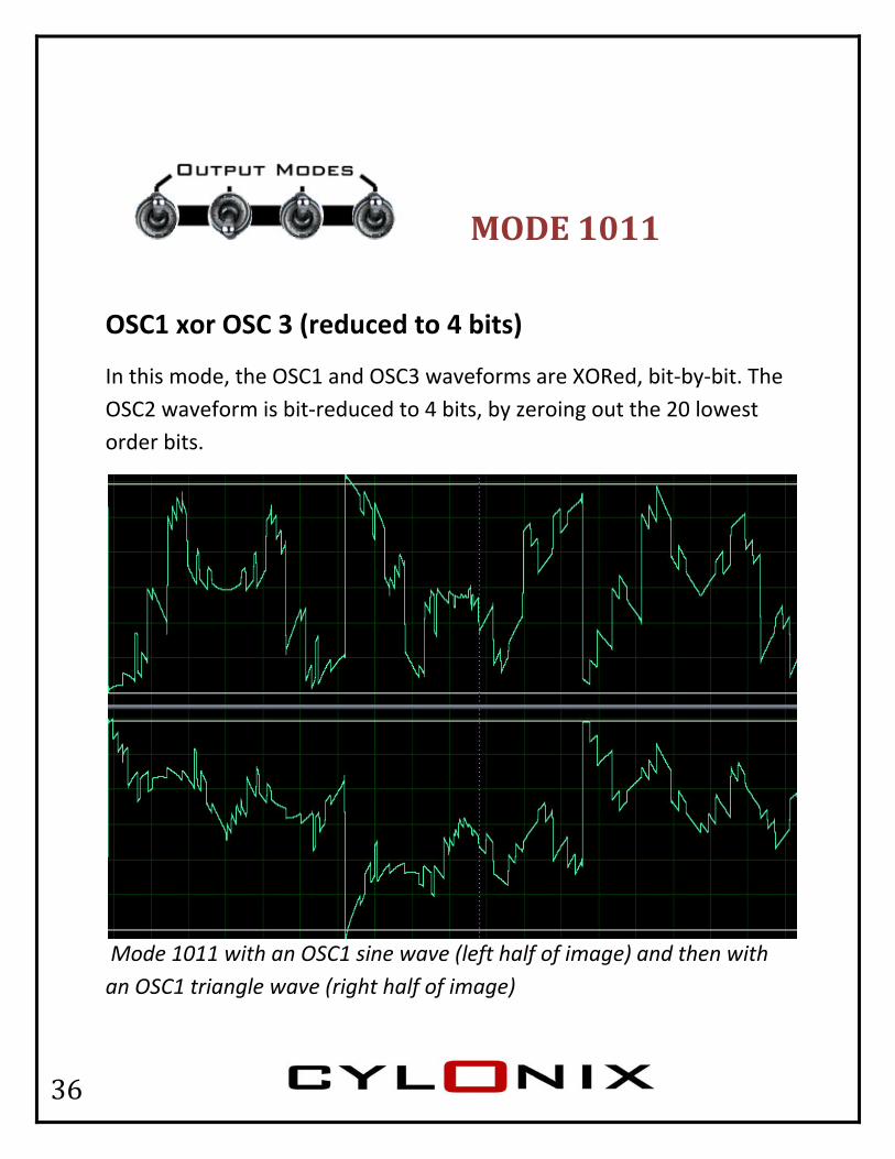
OSC1 xor OSC 3 (reduced to 4 bits)
In this mode, the OSC1 and OSC3 waveforms are XORed, bit‐by‐bit. The OSC2 waveform is bit‐reduced to 4 bits, by zeroing out the 20 lowest order bits.
Mode 1011 with an OSC1 sine wave (left half of image) and then with an OSC1 triangle wave (right half of image)
37
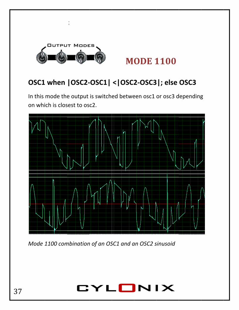
OSC1
In this on whi
Mode 1
1 when
mode theich is clos
1100 com
|OSC2‐
e output sest to os
mbination
‐OSC1|
is switchc2.
n of an OS
MO
<|OSC2
ed betwe
SC1 and a
ODE 1
2‐OSC3
een osc1 o
an OSC2 s
1100
3|; else
or osc3 d
sinusoid
OSC3
dependingg

38
MODE 1101
OSC1 when OSC3(N) = 1; OSC2 when OSC3(N) = 0
In this mode the output alternates between OSC1 and OSC2. OSC2 is passed through whenever the Nth bit of OSC3 is 0, and OSC1 is passed whenever the Nth bit of OSC3 is 1. N is set by the PH2 control or input. For the PH2 control fully counter‐clockwise to around 12 o’clock, N is set to 23 (most significant bit). As the PH2 control is turned clockwise, N goes to 22, then to 21, and finally to 20. As N goes from 23 to 22 to 21 to 20, the number of alterations per cycle of OSC3 increases from 2 to 4 to 8 to 16.
Mode 1101 combination of an OSC1 sawtooth and an OSC2 sinusoid

39
MODE 1110
Positive part of OSC1 and negative part of OSC2 otherwise zero
In this mode the output is equal to OSC1 if OSC1 is positive, otherwise it is equal to OSC2 if OSC2 is negative. If neither of these conditions hold (i.e. OSC1 is negative and OSC2 is positive) then the output is zero. This produces a waveform with a central flat spot and different shapes in the positive and negative parts.
Mode 1110 combination of an OSC1 sawtooth and an OSC2 sinusoid

40
Oscill
This mdifferecycle wprovidto catc
Mode 1
lator 2 w
ode has tence – oscwhenevere decayinch up to t
1111 com
with re
the samecillator 2 r the lag ong runs ofhe value
mbination
eset whe
structureis reset (soutputs of pulses inof oscilla
n of an OS
MO
en OSC
e as modsynchronof oscillaton the outtor 1.
SC1 sinuso
ODE 1
C1=OSC2
e 0001, wized) to tor 1 and 2put of os
oid and a
1111
2
with one ihe begin2 are equscillator 2
an OSC2 s
importanning of itual. This c, as it trie
inepulse1
nt s can es
1

41
Outp
for theclockwon the
put G
e lowest nwise. The lsoundca
Gain an
noise outplevel shiftrd input,
nd WThouto attjacGAinskno
If tsigasydiagai
put set tht in the figand is no
Wavefoe GAIN intput signabout 4.0tenuates tck. If thereAIN jack, astead. In tob varies
the gain isgnal will stymmetricagram bein amplifihe GAIN cgure beloot actually
orm Fonput setsals. The g0. The GAthe signae is nothia +12V levthis case s the gain
s higher ttart foldincal mannelow. Noteies the nocontrol fuow is due y present
oldingthe levelgain rangeAIN controal input toing pluggvel is switthe GAINfrom 1 to
than 1 theng back oer, as shoe that incoise in thelly counteto the ACt in the ou
g of the es from 1ol knob o the GAINed into thtched in N control o about 4
e output on itself inwn in thereasing the output,er‐C couplinutput wav
1.0
N he
4.
n an e he , so
g ve.

42
InteThe iFMmodul
The figmodulfrequethe OSsawtooOSC2 pto fall.
In outpof the produc
ernal FM input aation of O
gure abovation. In tency squaSC2 wave oth is risinpasses th
put modeLAG outpce bendin
Frequand contrOSC1 by t
ve shows this examre‐wave is positivng. Whenrough zer
e 0001 theput that isng of the
uencyol sets ththe outpu
coof no
the “thromple, OSCand OSC1ve the fren the OSCro to neg
e iFM inps fed backOSC2 wav
y Modhe level ofut of OSC2mputed a24MHz, w
oise, and h
ough‐zeroC2 is gene1 is generquency oC2 wave isative freq
put and cok to the Oveform a
dulatiof the inte2. This mat the intwhich reshigh qual
o” nature erating a rrating a saof OSC2 iss negativequency, c
ontrol alsOSC2 phand even c
on ernal freqodulationernal samsults in loity modu
of the frerelativelyawtooth s positive e the freqcausing th
o adjustsse input. chaotic b
uency n is mpling ratow aliasinulation.
equency y low‐wave. Wand the quency ofhe sawtoo
s the amoThis can
behaviour
te g
hen
f oth
ount
r.

43
OSC
used to
The PHthe 8 o
C2 Pha
o provide
H2 input aoscillators
ase Co
e phase m
and contrs that cre
ontroThsignolevthOS
Thouinves
In knth
modulatio
rol also seate the M
ol he PH2 cognal inputothing pluvel is swite PH2 coSC2 over a
he PH2 coutput comvolve botpecially w
output mnob sets te LAG ann of OSC2
ets the amMEGA wav
ontrol knot to the Pugged intotched in introl knoa range o
ontrol is mmbinationh oscillatwith inter
mode 000he phased LEAD o2.
mount of veforms.
ob attenuPH2 jack. Io the PH2nstead. Inb varies tof 360 deg
most usefu modes wtors 1 andrnal sync t
01 the PH2 differencutputs. T
detuning
ates the If there is2 jack, a +n this casthe phasegrees.
ul in thoswhich d 2, turned on
2 input ace betweThis can b
g between
s +9V e e of
se
n.
nd en e
n
44
OSC
ratio o10V inp
C2/OS
f 1, whileput gives
SC1 Ra
e a +10V ia ratio o
atio Thbecofre
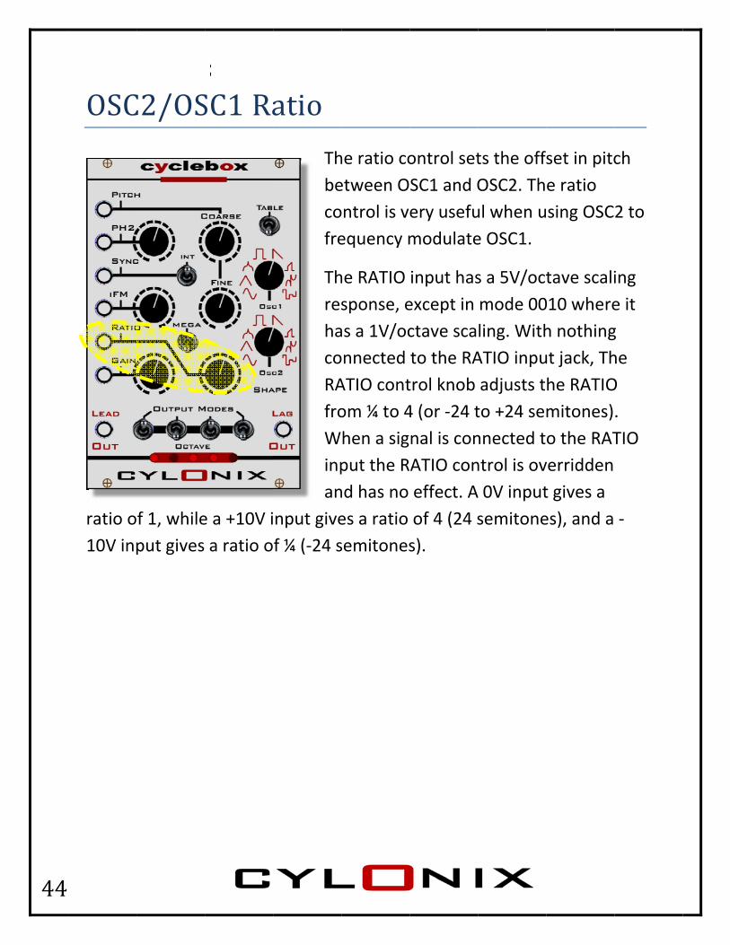
ThreshacoRAfroWinpan
nput givef ¼ (‐24 s
he ratio coetween Oontrol is vequency m
he RATIO sponse, eas a 1V/oconnected ATIO contom ¼ to 4hen a sigput the Rnd has no es a ratio semitones
ontrol setSC1 and Oery usefumodulate
input hasexcept in ctave scato the RAtrol knob 4 (or ‐24 tnal is conATIO coneffect. Aof 4 (24 ss).
ts the offOSC2. Thul when ue OSC1.
s a 5V/octmode 00ling. WithATIO inpuadjusts tto +24 sennected tntrol is ovA 0V inputsemitone
set in pitce ratio sing OSC
tave scali010 whereh nothingut jack, Thhe RATIOmitones)o the RATverridden t gives a es), and a
ch
2 to
ing e it g he O . TIO
‐

45
Osci
presenreset tSYNC isignal. extern
illator
nt at the So their benput lockThe imagal pulse t
r Syn
SYNC jackeginningsks the freqge below train inpu
c ThOswicypu
Wposyno(exseeff
Wk the wavs. Connecquency oshows th
ut on osci
he startingscillator 2ith eitherycle or to ulse input
When the Iosition, osnchronizeot have anxcept whelected), bfect on o
When a lareforms octing a repf the oscihe effect llator 1’s
g of the O2 cycles car the startthe occut to the SY
INT switcscillators ed to oscny effect en the Mbut therescillator 2
rge enougof oscillatopetitive pillators toof synchrsine wav
Oscillatoran be synt of the Orrence ofYNC jack.
h is in the1 and 2 acillator 3. on oscilla
MEGA mod can be a2.
gh positivor 1, 2 anpulse signo that of tronizing tveform in
r 1 and nchronizeOscillator f an exter
e upwardare This doesator 1 de is significa
ve pulse isnd 3 are aal to the this pulseo an mode 00
ed 3 rnal
ds
s
nt
s ll
e
000.
46
Meg
MEGA
ga Mo
mode wi
ode
ith OSC1 w
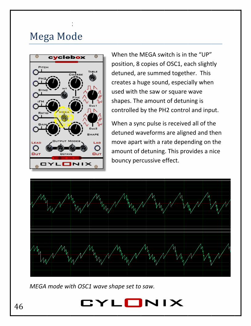
Wpodecreusshco
Wdemoambo
wave sha
hen the Mosition, 8 etuned, areates a hed with tapes. Theontrolled b
hen a synetuned waove apartmount of ouncy per
ape set to
MEGA swcopies ofre summeuge sounthe saw oe amountby the PH
nc pulse iaveformst with a radetuningrcussive e
saw.
witch is in f OSC1, eaed togethd, especi
or square t of detunH2 contro
s receives are alignate depeg. This proeffect.
the “UP”ach slighther. This ally whenwave ning is ol and inp
d all of thned and tnding on ovides a n
” tly
n
ut.
he hen the nice

47
OCT
Then areadingjust beflicker
The octhe pit“Cylon
If the ofrequeLEDs inindicatnegativ
TAVE/
adjust theg transitioefore the just stop
ctave readch. If then” scannin
octave is ency), thendicate thte the LAGve levels,
/Tuni
e Coarse aons fromtransitions.
ding is disre is no cng pattern
10001 or output lehe LEAD oG output and the
ng/LFThdispitnulowC) oc
Threabemisuint
and Fine p 10111 ton. Adjust
splayed fochange in n is displa
lower (eevel is indoutput levlevel. Theright LED
FO Dihe five LEDsplay the tch. This iumber, wwest octaand 1111
ctave (9 o
he lowest ading is te used to iddle‐C pipply a votended topitch cono 11000. Tthe Fine
or about pitch forayed.
.g. the Cydicated bvel and the left LEDDs light up
isplayDs under current ois displayith 00000ave (22 oc11 represctaves ab
pitch in ahe “C” oftune the itch (261.oltage to to corresptrols so tThe LEDspitch con
4 secondr 4 second
yclebox isy the LEDhe rightmDs in eachp for posit
y the OCTAoctave ofed as a 50 represectaves besenting thbove midd
a given ocf that octaoscillato.6 Hertz).the Pitch ond to mhat the os will flickntrol so th
s after a ds a back
s running Ds. The lemost two Lh pair lightive level
AVE labelf OSC1’s ‐bit binarnting theelow middhe highesdle‐C).
ctave ave. This r to conce. To do thinput tha
middle‐C. octave er slightlyhat the
change in‐and‐fort
at an “LFftmost twLEDs t up for s.
l
ry e dle‐t
can ert his, at is
y
n th
FO” wo

48
Tuning Scale Adjustment The 1V/octave scale factor for the PITCH and RATIO inputs is preset at the factory. It should not need to be adjusted again. But if for some reason the tuning scale seems to have gone off, you can do the adjustment yourself with the following procedure:
1. Input a 0‐volt signal into the PITCH input (e.g. this could come from the output of a MIDI‐CV converter, or from a precision voltage source). Press the lower of the two push buttons on the rear circuit board.
2. Next, input a 1‐volt signal into the PITCH input (e.g. from the MIDI‐CV converter one octave higher). Press the upper of the two push buttons on the rear circuit board. The system should now have the desired 1 Volt per octave tuning scale.
3. This can be used to obtain other tuning scales if needed. The key is to enter two voltages that are intended to represent one octave difference. So, if you wanted to have a ½ volt per octave scaling, the second voltage entered should be ½ volts.

49
Module Expansion (optional!) The Cyclebox module can be optionally expanded to provide up to 8 additional operational modes. The expansion modes are accessed via the left‐hand (as viewed from the rear) 40‐pin IDC connector (labeled GPIO1) on the rear circuit board.
Pin 1 of the connector is on the bottom right of the two rows of pins as seen from the back, as shown in the diagram.
The individual expansion modes are activated when their associated pins are
driven low (to ground voltage) and deactivated when the pin is floating. More than one expansion mode can be activated at the same time if desired.
The mapping of the connector pins to the expansion modes is given on the next page.

50
The following table shows the mapping between expansion modes and the pins on a matching female 40‐pin connector to plug in to the left hand expansion connector. Do not connect to any of the other pins.
PIN NUMBER Expansion Mode23 Non‐through Zero FM24 Alternative Waveshapes 25 Wide‐range MEGA26 One‐Shot27 Percussive28 Reverse Soft‐Sync30 Ground31 +2 Octave Shift32 LFO Mode
An expander module consists of a set of single‐pole‐single‐throw (SPST) switches which pull the appropriate expansion mode lines to ground when switched, as suggested in the following example circuit:
GROUND (connect to pin 30)
Connect to expansion connector pin associated with the desired mode
SPST switch
51
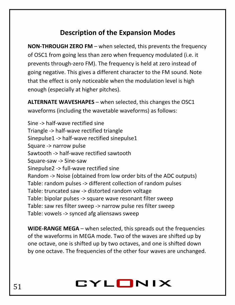
Description of the Expansion Modes
NON‐THROUGH ZERO FM – when selected, this prevents the frequency of OSC1 from going less than zero when frequency modulated (i.e. it prevents through‐zero FM). The frequency is held at zero instead of going negative. This gives a different character to the FM sound. Note that the effect is only noticeable when the modulation level is high enough (especially at higher pitches).
ALTERNATE WAVESHAPES – when selected, this changes the OSC1 waveforms (including the wavetable waveforms) as follows:
Sine ‐> half‐wave rectified sine Triangle ‐> half‐wave rectified triangle Sinepulse1 ‐> half‐wave rectified sinepulse1 Square ‐> narrow pulse Sawtooth ‐> half‐wave rectified sawtooth Square‐saw ‐> Sine‐saw Sinepulse2 ‐> full‐wave rectified sine Random ‐> Noise (obtained from low order bits of the ADC outputs) Table: random pulses ‐> different collection of random pulses Table: truncated saw ‐> distorted random voltage Table: bipolar pulses ‐> square wave resonant filter sweep Table: saw res filter sweep ‐> narrow pulse res filter sweep Table: vowels ‐> synced afg aliensaws sweep WIDE‐RANGE MEGA – when selected, this spreads out the frequencies of the waveforms in MEGA mode. Two of the waves are shifted up by one octave, one is shifted up by two octaves, and one is shifted down by one octave. The frequencies of the other four waves are unchanged.
52
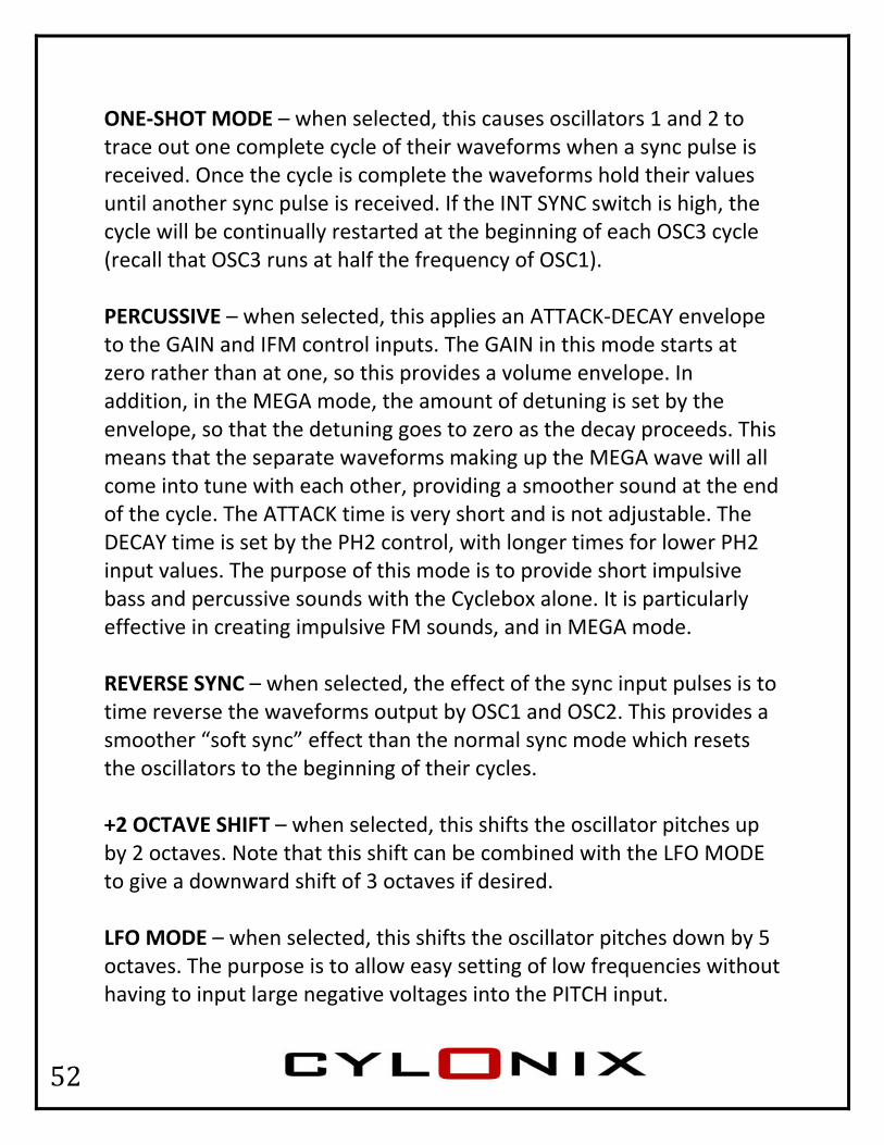
ONE‐SHOT MODE – when selected, this causes oscillators 1 and 2 to trace out one complete cycle of their waveforms when a sync pulse is received. Once the cycle is complete the waveforms hold their values until another sync pulse is received. If the INT SYNC switch is high, the cycle will be continually restarted at the beginning of each OSC3 cycle (recall that OSC3 runs at half the frequency of OSC1). PERCUSSIVE – when selected, this applies an ATTACK‐DECAY envelope to the GAIN and IFM control inputs. The GAIN in this mode starts at zero rather than at one, so this provides a volume envelope. In addition, in the MEGA mode, the amount of detuning is set by the envelope, so that the detuning goes to zero as the decay proceeds. This means that the separate waveforms making up the MEGA wave will all come into tune with each other, providing a smoother sound at the end of the cycle. The ATTACK time is very short and is not adjustable. The DECAY time is set by the PH2 control, with longer times for lower PH2 input values. The purpose of this mode is to provide short impulsive bass and percussive sounds with the Cyclebox alone. It is particularly effective in creating impulsive FM sounds, and in MEGA mode. REVERSE SYNC – when selected, the effect of the sync input pulses is to time reverse the waveforms output by OSC1 and OSC2. This provides a smoother “soft sync” effect than the normal sync mode which resets the oscillators to the beginning of their cycles. +2 OCTAVE SHIFT – when selected, this shifts the oscillator pitches up by 2 octaves. Note that this shift can be combined with the LFO MODE to give a downward shift of 3 octaves if desired. LFO MODE – when selected, this shifts the oscillator pitches down by 5 octaves. The purpose is to allow easy setting of low frequencies without having to input large negative voltages into the PITCH input.
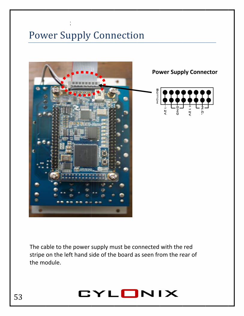
53
Pow
The castripe the mo
wer Su
able to thon the leodule.
upply
e power eft hand s
Conn
supply mide of the
nectio
must be coe board a
on
Pow
onnected as seen fro
wer Supp
with the om the re
ply Conne
red ear of
ector

54
Output Offset Adjustment To set the output offset voltage (normally this should be set to zero so that the output waveforms are symmetric about zero volts), connect an oscilloscope or voltmeter to the LAG output. Set the output mode switches to 1000 (leftmost switch up, the others down). Select the wave shapes for OSC1 and OSC2 to SQUARE. With these settings the LAG output should be constant. Turn the offset adjust trimpot, located on the bottom of the front panel circuit board, so that the output voltage is zero.

55
Electrical and Mechanical Specifications Power Supply requirement: +12V@150mA and ‐12V@5mA This is the maximum expected current draw, which occurs at very high frequencies. In typical usage the current draw will be between 100mA and 120mA. The Cyclebox module has protection against reversal of the power supply voltages. However, reversal of the power connector will cause a short‐circuit of the +12V from the power supply and the +5V if it is present, possibly causing damage to the power supply.
Input Voltage Range: ± 10 Volts on all inputs.
Output Voltage Range: ± 5 Volts
Input Impedance: 10KOhms on the PH2 and iFM inputs, 100KOhms on the SYNC input, and 1MOhm on the PITCH, RATIO and GAIN inputs.
Size: 16 HP wide (3.2 inches) x 3U high (5.25 inches) x 1.75 inches deep (45 mm) (measured from the back of the front plate). The front plate is 2mm thick.

56
COMPLIANCE NOTICE This product is considered to be a subassembly to a digital device and as such is intended for use in a system that complies with applicable regulations. It is recommended that the module be contained in an electromagnetically shielded metal enclosure and that connections to the front panel jacks be made using shielded cables. Changes or modifications to the module not expressly approved by Cylonix for compliance could void the user's authority to operate the equipment.
This document is copyright technologie Cylonix 2011


