32
Appendix Page Relay Characteristics 15/2 Dimension Drawings 15/7 Assignment for Products 15/25 Order No. Index 15/26 Training 15/28 Books and Publications 15/29 15

Appendix Page
Relay Characteristics 15/2
Dimension Drawings 15/7
Assignment for Products 15/25
Order No. Index 15/26
Training 15/28
Books and Publications 15/29
15
15 Appendix
Siemens SIP · Edition No. 615/2
15
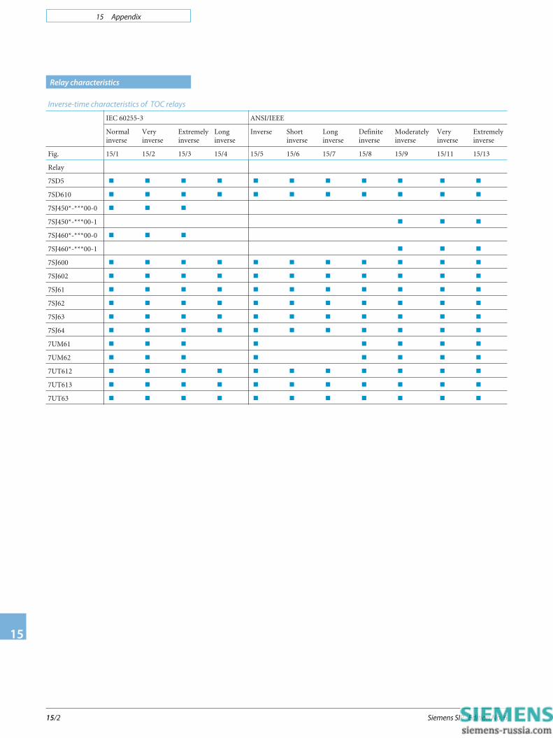
Relay characteristics
Inverse-time characteristics of TOC relays
IEC 60255-3 ANSI/IEEE
Normalinverse
Veryinverse
Extremelyinverse
Longinverse
Inverse Shortinverse
Longinverse
Definiteinverse
Moderatelyinverse
Veryinverse
Extremelyinverse
Fig. 15/1 15/2 15/3 15/4 15/5 15/6 15/7 15/8 15/9 15/11 15/13
Relay
7SD5 � � � � � � � � � � �
7SD610 � � � � � � � � � � �
7SJ450*-***00-0 � � �
7SJ450*-***00-1 � � �
7SJ460*-***00-0 � � �
7SJ460*-***00-1 � � �
7SJ600 � � � � � � � � � � �
7SJ602 � � � � � � � � � � �
7SJ61 � � � � � � � � � � �
7SJ62 � � � � � � � � � � �
7SJ63 � � � � � � � � � � �
7SJ64 � � � � � � � � � � �
7UM61 � � � � � � � �
7UM62 � � � � � � � �
7UT612 � � � � � � � � � � �
7UT613 � � � � � � � � � � �
7UT63 � � � � � � � � � � �
15 Appendix
Siemens SIP · Edition No. 6 15/3
15
Relay characteristics
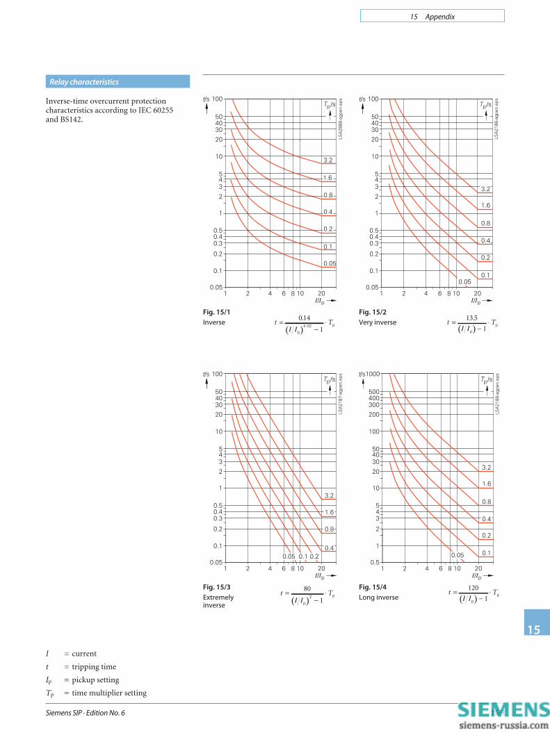
Fig. 15/1
Inverse
Fig. 15/2
Very inverse
Inverse-time overcurrent protectioncharacteristics according to IEC 60255and BS142.
( )t T=
−⋅13 5
1
.
I Ipp( )
t T=−
⋅0 14
10 02
..
I Ip
p
Fig. 15/3
Extremely
inverse
Fig. 15/4
Long inverse ( )t T=
−⋅120
1I Ipp
( )t T=
−⋅80
1I Ip2 p
I = current
t = tripping time
Ip = pickup setting
Tp = time multiplier setting

15 Appendix
Siemens SIP · Edition No. 615/4
15
Relay characteristics
Fig. 15/5
Inverse
Fig. 15/6
Short inverse
Fig. 15/7
Long inverse
Fig. 15/8
Definite
inverse
t =−
+⎛⎝⎜ ⎞
⎠⎟ ⋅0 2663
10 03393
1 2969
..
.MTDt =
−+⎛
⎝⎜ ⎞
⎠⎟ ⋅8 9341
10 17966
2 0938
..
.MTD
t =−
+⎛⎝⎜ ⎞
⎠⎟ ⋅5 6143
12 18592
..
MTD t =
−+⎛
⎝⎜ ⎞
⎠⎟ ⋅0 4797
10 21359
1 5625
..
.MTD
t = tripping time in seconds
M = current in multiples of pickupsetting (I/Ip) range 0.1 to 4
TD = time dial
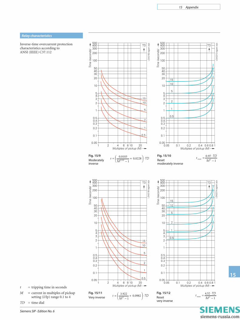
Inverse-time overcurrent protectioncharacteristics according toANSI (IEEE) C37.112
15 Appendix
Siemens SIP · Edition No. 6 15/5
15
Relay characteristics
Fig. 15/9
Moderately
inverse
Fig. 15/10
Reset
moderately inverse
Fig. 15/11
Very inverse
Fig. 15/12
Reset
very inverse
t reset 2= ⋅
−4 32
1
. TDM
t =−
+⎛⎝⎜ ⎞
⎠⎟ ⋅3 922
10 0982
..
MTD
2
t =−
+⎛⎝⎜ ⎞
⎠⎟ ⋅0 0103
10 0228
..
MTD
0.02t reset 2
= ⋅−
0 97
1
. TDM
Inverse-time overcurrent protectioncharacteristics according toANSI (IEEE) C37.112
t = tripping time in seconds
M = current in multiples of pickupsetting (I/Ip) range 0.1 to 4
TD = time dial
15
15 Appendix
Siemens SIP · Edition No. 615/6
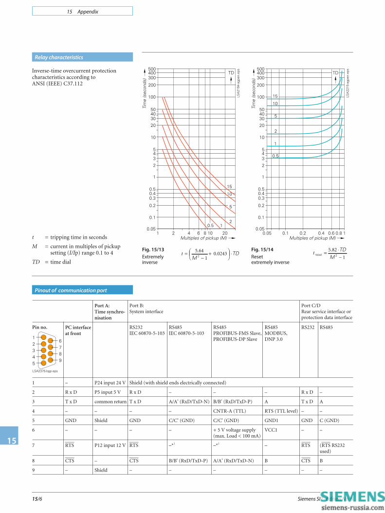
Relay characteristics
Fig. 15/13
Extremely
inverse
Fig. 15/14
Reset
extremely inverse
t =−
+⎛⎝⎜ ⎞
⎠⎟ ⋅5 64
10 0243
2
..
MTD t reset 2
= ⋅−
5 82
1
. TDM
Inverse-time overcurrent protectioncharacteristics according toANSI (IEEE) C37.112
t = tripping time in seconds
M = current in multiples of pickupsetting (I/Ip) range 0.1 to 4
TD = time dial
Pinout of communication port
Port A:Time synchro-nisation
Port B:System interface
Port C/DRear service interface orprotection data interface
Pin no. PC interfaceat front
RS232IEC 60870-5-103
RS485IEC 60870-5-103
RS485PROFIBUS-FMS Slave,PROFIBUS-DP Slave
RS485MODBUS,DNP 3.0
RS232 RS485
1 – P24 input 24 V Shield (with shield ends electrically connected)
2 R x D P5 input 5 V R x D – – – R x D –
3 T x D common return T x D A/A' (RxD/TxD-N) B/B' (RxD/TxD-P) A T x D A
4 – – – – CNTR-A (TTL) RTS (TTL level) – –
5 GND Shield GND C/C' (GND) C/C' (GND) GND1 GND C (GND)
6 – – – – + 5 V voltage supply(max. Load < 100 mA)
VCC1 – –
7 RTS P12 input 12 V RTS –*) –*) – RTS (RTS RS232used)
8 CTS – CTS B/B' (RxD/TxD-P) A/A' (RxD/TxD-N) B CTS B
9 – Shield – – – – – –
15 Appendix
Siemens SIP · Edition No. 6 15/7
15
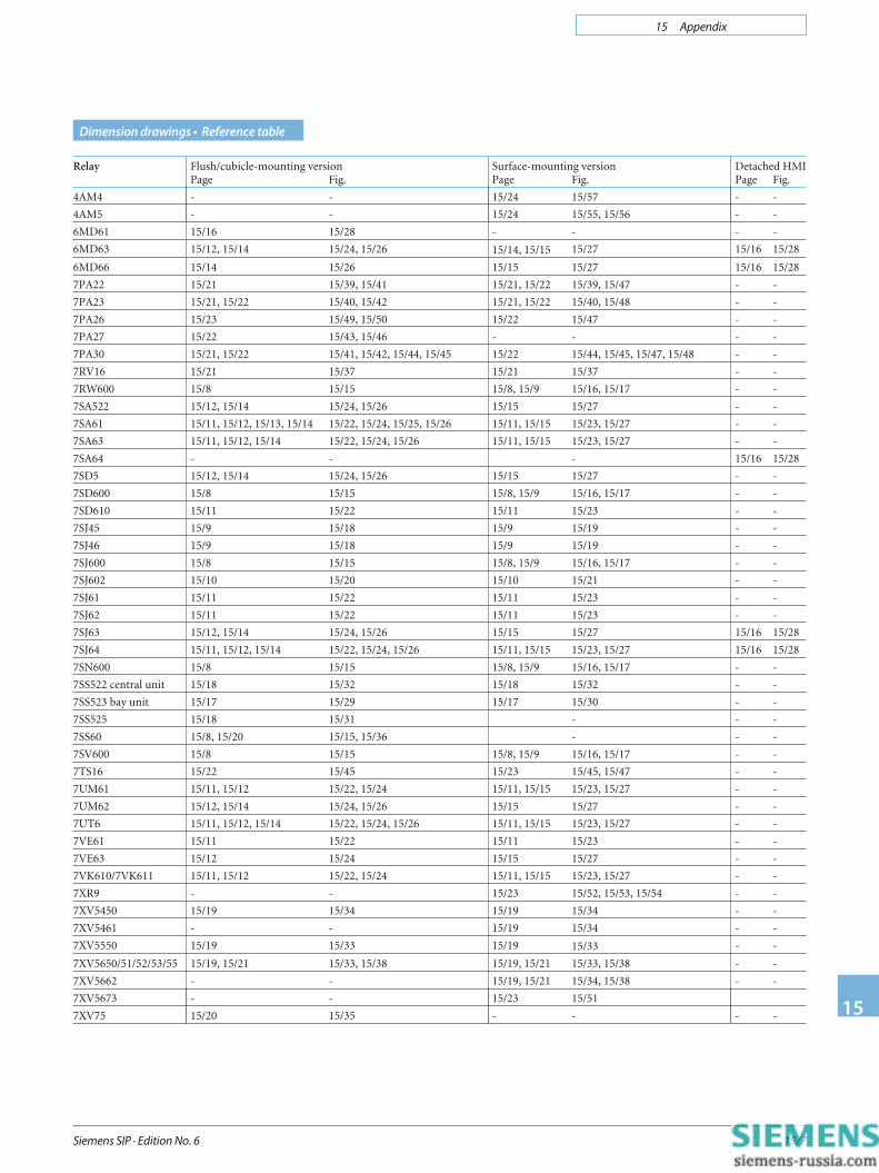
Dimension drawings • Reference table
Relay Flush/cubicle-mounting versionPage Fig.
Surface-mounting versionPage Fig.
Detached HMIPage Fig.
4AM4 - - 15/24 15/57 - -
4AM5 - - 15/24 15/55, 15/56 - -
6MD61 15/16 15/28 - - - -
6MD63 15/12, 15/14 15/24, 15/26 15/14, 15/15 15/27 15/16 15/28
6MD66 15/14 15/26 15/15 15/27 15/16 15/28
7PA22 15/21 15/39, 15/41 15/21, 15/22 15/39, 15/47 - -
7PA23 15/21, 15/22 15/40, 15/42 15/21, 15/22 15/40, 15/48 - -
7PA26 15/23 15/49, 15/50 15/22 15/47 - -
7PA27 15/22 15/43, 15/46 - - - -
7PA30 15/21, 15/22 15/41, 15/42, 15/44, 15/45 15/22 15/44, 15/45, 15/47, 15/48 - -
7RV16 15/21 15/37 15/21 15/37 - -
7RW600 15/8 15/15 15/8, 15/9 15/16, 15/17 - -
7SA522 15/12, 15/14 15/24, 15/26 15/15 15/27 - -
7SA61 15/11, 15/12, 15/13, 15/14 15/22, 15/24, 15/25, 15/26 15/11, 15/15 15/23, 15/27 - -
7SA63 15/11, 15/12, 15/14 15/22, 15/24, 15/26 15/11, 15/15 15/23, 15/27 - -
7SA64 - - - 15/16 15/28
7SD5 15/12, 15/14 15/24, 15/26 15/15 15/27 - -
7SD600 15/8 15/15 15/8, 15/9 15/16, 15/17 - -
7SD610 15/11 15/22 15/11 15/23 - -
7SJ45 15/9 15/18 15/9 15/19 - -
7SJ46 15/9 15/18 15/9 15/19 - -
7SJ600 15/8 15/15 15/8, 15/9 15/16, 15/17 - -
7SJ602 15/10 15/20 15/10 15/21 - -
7SJ61 15/11 15/22 15/11 15/23 - -
7SJ62 15/11 15/22 15/11 15/23 - -
7SJ63 15/12, 15/14 15/24, 15/26 15/15 15/27 15/16 15/28
7SJ64 15/11, 15/12, 15/14 15/22, 15/24, 15/26 15/11, 15/15 15/23, 15/27 15/16 15/28
7SN600 15/8 15/15 15/8, 15/9 15/16, 15/17 - -
7SS522 central unit 15/18 15/32 15/18 15/32 - -
7SS523 bay unit 15/17 15/29 15/17 15/30 - -
7SS525 15/18 15/31 - - -
7SS60 15/8, 15/20 15/15, 15/36 - - -
7SV600 15/8 15/15 15/8, 15/9 15/16, 15/17 - -
7TS16 15/22 15/45 15/23 15/45, 15/47 - -
7UM61 15/11, 15/12 15/22, 15/24 15/11, 15/15 15/23, 15/27 - -
7UM62 15/12, 15/14 15/24, 15/26 15/15 15/27 - -
7UT6 15/11, 15/12, 15/14 15/22, 15/24, 15/26 15/11, 15/15 15/23, 15/27 - -
7VE61 15/11 15/22 15/11 15/23 - -
7VE63 15/12 15/24 15/15 15/27 - -
7VK610/7VK611 15/11, 15/12 15/22, 15/24 15/11, 15/15 15/23, 15/27 - -
7XR9 - - 15/23 15/52, 15/53, 15/54 - -
7XV5450 15/19 15/34 15/19 15/34 - -
7XV5461 - - 15/19 15/34 - -
7XV5550 15/19 15/33 15/19 15/33 - -
7XV5650/51/52/53/55 15/19, 15/21 15/33, 15/38 15/19, 15/21 15/33, 15/38 - -
7XV5662 - - 15/19, 15/21 15/34, 15/38 - -
7XV5673 - - 15/23 15/51
7XV75 15/20 15/35 - - - -
15 Appendix
Siemens SIP · Edition No. 615/8
15
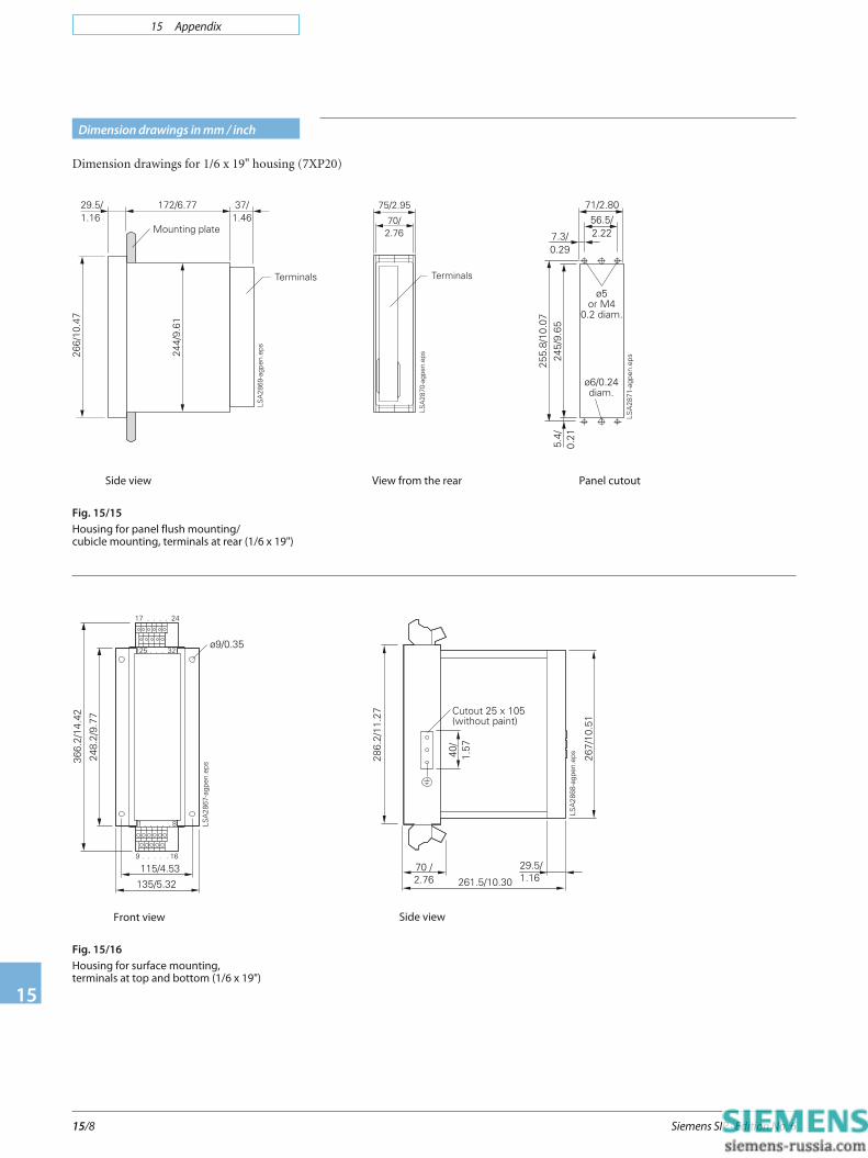
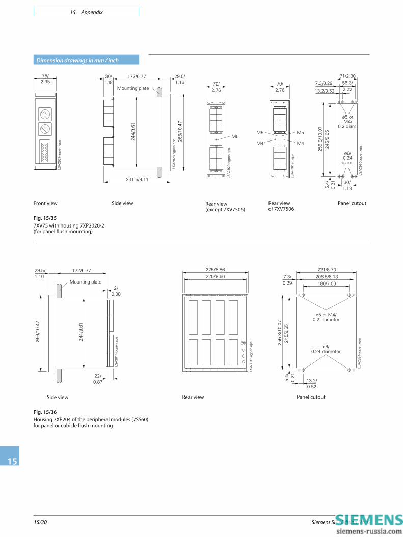
Dimension drawings in mm / inch
Side view
Fig. 15/15
Housing for panel flush mounting/
cubicle mounting, terminals at rear (1/6 x 19")
Front view
Fig. 15/16
Housing for surface mounting,
terminals at top and bottom (1/6 x 19")
Dimension drawings for 1/6 x 19" housing (7XP20)
View from the rear Panel cutout
Side view

15 Appendix
Siemens SIP · Edition No. 6 15/9
15
Dimension drawings in mm / inch
Side view
Dimension drawings for 1/6 x 19" housing (7XP20)
Front view
Fig. 15/17
Housing for panel surface mounting,
terminals on the side (1/6 x 19")
Fig. 15/18
7SJ45, 7SJ46 housing for panel flush mounting
Dimension drawings for SIPROTEC easy
Panel cutout
Fig. 15/19
7SJ45, 7SJ46 housing for rail mounting
15 Appendix
Siemens SIP · Edition No. 615/10
15
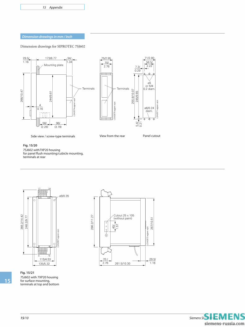
Side view / screw-type terminals
Fig. 15/20
7SJ602 with7XP20 housing
for panel flush mounting/cubicle mounting,
terminals at rear
View from the rear Panel cutout
Dimension drawings in mm / inch
Fig. 15/21
7SJ602 with 7XP20 housing
for surface mounting,
terminals at top and bottom
Dimension drawings for SIPROTEC 7SJ602
15 Appendix
Siemens SIP · Edition No. 6 15/11
15
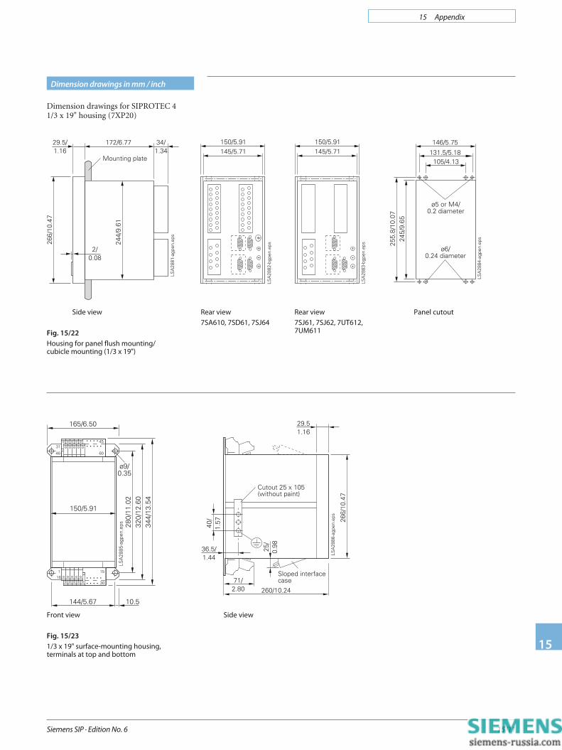
Dimension drawings in mm / inch
Front view
Fig. 15/23
1/3 x 19" surface-mounting housing,
terminals at top and bottom
Side view
Fig. 15/22
Housing for panel flush mounting/
cubicle mounting (1/3 x 19")
Dimension drawings for SIPROTEC 41/3 x 19" housing (7XP20)
Rear view
7SA610, 7SD61, 7SJ64
Rear view
7SJ61, 7SJ62, 7UT612,
7UM611
Panel cutout
Side view
15 Appendix
Siemens SIP · Edition No. 615/12
15
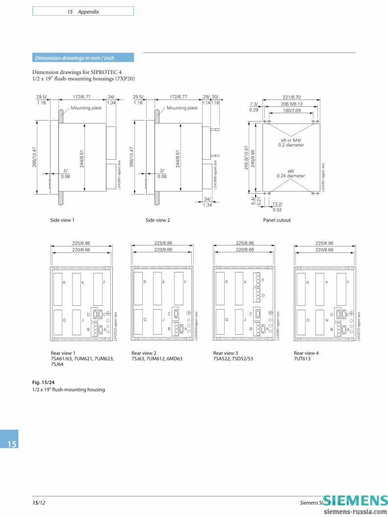
Dimension drawings in mm / inch
Dimension drawings for SIPROTEC 41/2 x 19" flush-mounting housings (7XP20)
Side view 1 Side view 2 Panel cutout
Rear view 1
7SA61/63, 7UM621, 7UM623,
7SJ64
Rear view 2
7SJ63, 7UM612, 6MD63
Rear view 3
7SA522, 7SD52/53
Fig. 15/24
1/2 x 19" flush-mounting housing
Rear view 4
7UT613

15 Appendix
Siemens SIP · Edition No. 6 15/13
15
Dimension drawings in mm / inch
Dimension drawings for SIPROTEC 42/3 x 19" flush-mounting housings (7XP20)
Side view
Fig. 15/25
2/3 x 19" flush-mounting housing for 7SA613
Rear view Panel cutout
15 Appendix
Siemens SIP · Edition No. 615/14
15
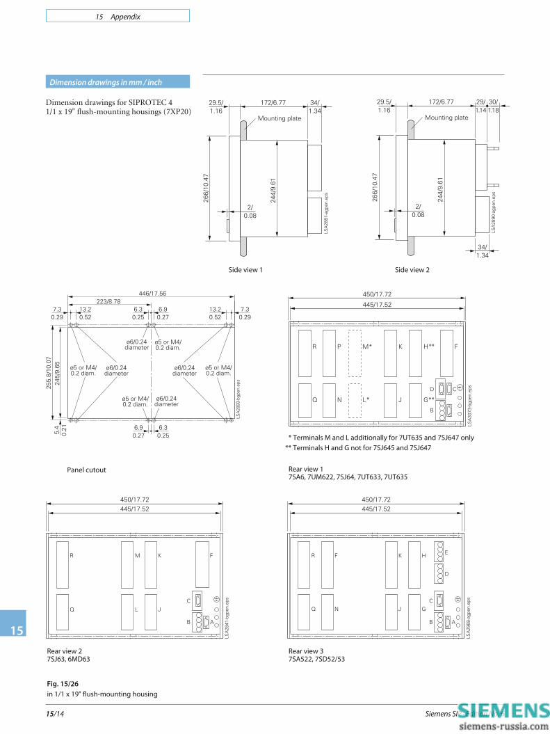
Dimension drawings in mm / inch
Dimension drawings for SIPROTEC 41/1 x 19" flush-mounting housings (7XP20)
Side view 1 Side view 2
Panel cutout Rear view 1
7SA6, 7UM622, 7SJ64, 7UT633, 7UT635
Rear view 3
7SA522, 7SD52/53
Rear view 2
7SJ63, 6MD63
Fig. 15/26
in 1/1 x 19" flush-mounting housing
* Terminals M and L additionally for 7UT635 and 7SJ647 only
** Terminals H and G not for 7SJ645 and 7SJ647

15 Appendix
Siemens SIP · Edition No. 6 15/15
15
Front view
1/1 x 19" surface-mounting housing 7XP20
(without sloped FO case)
Dimension drawings in mm / inch
Front view
1/2 x 19" surface-mounting,
terminals at top and bottom
housing 7XP20
Side view
Dimension drawings for SIPROTEC 41/2 and 1/1 x 19" surface-mounting housings(7XP20)
Fig. 15/27
1/2 and 1/1 x 19" surface-mounting housing
15 Appendix
Siemens SIP · Edition No. 615/16
15
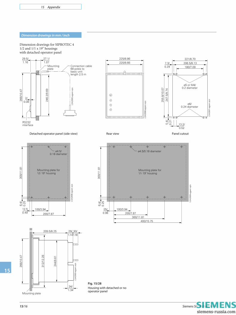
Dimension drawings in mm / inch
Fig. 15/28
Housing with detached or no
operator panel
Dimension drawings for SIPROTEC 41/2 and 1/1 x 19" housingswith detached operator panel
Detached operator panel (side view) Rear view Panel cutout

15 Appendix
Siemens SIP · Edition No. 6 15/17
15
Dimension drawings in mm / inch
Front view
Fig. 15/29
7SS523 bay unit in 7XP2040-2 housing
for panel flush mounting/cubicle mounting
Front view
Fig. 15/30
7SS523 bay unit in 7XP2040-1 housing for
panel surface mounting
Side view Panel cutout
Side view View from below
15 Appendix
Siemens SIP · Edition No. 615/18
15
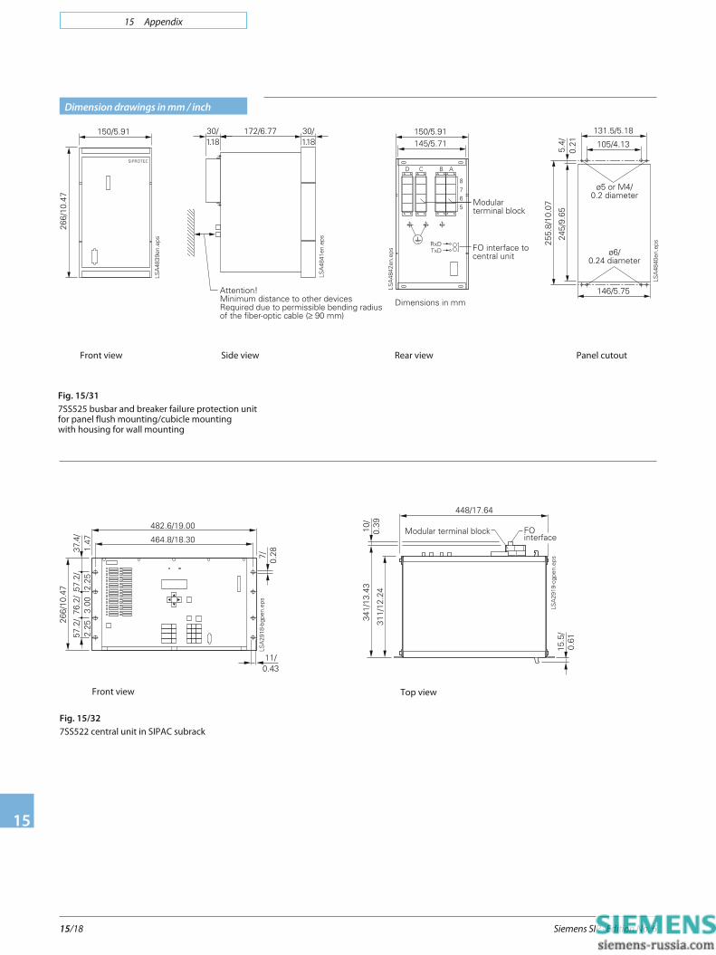
Dimension drawings in mm / inch
Fig. 15/31
7SS525 busbar and breaker failure protection unit
for panel flush mounting/cubicle mounting
with housing for wall mounting
Front view Side view
Front view
Fig. 15/32
7SS522 central unit in SIPAC subrack
Top view
Rear view Panel cutout

15 Appendix
Siemens SIP · Edition No. 6 15/19
15
Dimension drawings in mm / inch
Fig. 15/33
Converter devices for rail mounting
Fig. 15/34
7XV5662 communication converter
15 Appendix
Siemens SIP · Edition No. 615/20
15
Dimension drawings in mm / inch
Front view
Fig. 15/35
7XV75 with housing 7XP2020-2
(for panel flush mounting)
Side view
Fig. 15/36
Housing 7XP204 of the peripheral modules (7SS60)
for panel or cubicle flush mounting
Side view
Rear view Panel cutout
Rear view
(except 7XV7506)
Panel cutoutRear view
of 7XV7506
15 Appendix
Siemens SIP · Edition No. 6 15/21
15
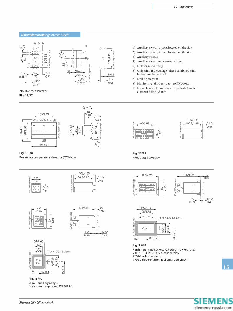
Dimension drawings in mm / inch
7RV16 circuit-breaker
Fig. 15/37
1) Auxiliary switch, 2-pole, located on the side.
2) Auxiliary switch, 4-pole, located on the side.
3) Auxiliary release.
4) Auxiliary switch transverse position.
5) Link for screw fixing.
6) Only with undervoltage release combined withleading auxiliary switch.
7) Drilling diagram.
8) Monitoring rail 35 mm, acc. to EN 50022.
11 Lockable in OFF position with padlock, bracketdiameter 3.5 to 4.5 mm
Fig. 15/38
Resistance temperature detector (RTD-box)
Fig. 15/39
7PA22 auxiliary relay
Fig. 15/41
Flush mounting sockets 7XP9010-1, 7XP9010-2,
7XP9010-4 for 7PA22 auxiliary relay
7TS16 indication relay
7PA30 three-phase trip circuit supervision
Fig. 15/40
7PA23 auxiliary relay +
flush mounting socket 7XP9011-1

15 Appendix
Siemens SIP · Edition No. 615/22
15
Dimension drawings in mm / inch
Fig. 15/47
Surface mounting socket 7XP9012
7PA22, 7PA26 auxiliary relays
7TS16 indication relay
7PA30 three-phase trip circuit supervision
Fig. 15/42
Flush mounting sockets 7XP9011-0, 7XP9011-1
for 7PA23 auxiliary relay
7PA30 trip single-phase circuit supervision
Fig. 15/48
Surface mounting socket 7XP9013
for 7PA23/27 auxiliary relay
7PA30 single-phase trip circuit supervision
Fig. 15/43
7PA27
Fig. 15/44
7PA30 single-phase
Fig. 15/45
7TS16, 7PA30 three-phase
Fig. 15/46
Flush mounting socket 7XP9011-2
for 7PA27 auxiliary relay
15 Appendix
Siemens SIP · Edition No. 6 15/23
15
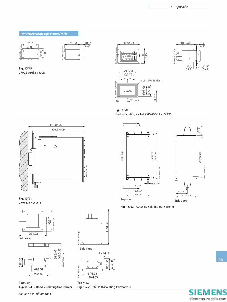
Dimension drawings in mm / inch
Fig. 15/50
Flush-mounting socket 7XP9010-3 for 7PA26
Fig. 15/49
7PA26 auxiliary relay
SIPV
6.0
93en
.ep
s
111.3/4.38
103.8/4.09
Fig. 15/51
7XV5673 I/O-Unit
125/4.92
95/3
.74
SIPV
6.08
7en.
eps
Top view
Fig. 15/53 7XR9515 isolating transformer
90/3.54
64/2.52
88/3
.46
38/1
.50 10
1/3.
98SI
PV6.
088e
n.ep
s
33
0/1
2.9
9
23
8/9
.37
25
0/9
.84
125/4.92
100/3.94
(7/0.28)
SIPV
6.0
74
en.e
ps
Top view
Fig. 15/52 7XR9513 isolating transformer
ca.5
5/
2.1
7(2
20
/8.6
6)
62/2.44
112/4.41
SIPV
6.0
75
en.e
psSide view
175/
6.89
SIPV
6.03
0en.
eps
Top view
Fig. 15/54 7XR9516 isolating transformer
97/3.28110/4.33
4 x ø4.5/0.18
50/1
.97
60/2
.36
SIPV
6.03
1en.
eps
Side view
Side view
15 Appendix
Siemens SIP · Edition No. 615/24
15
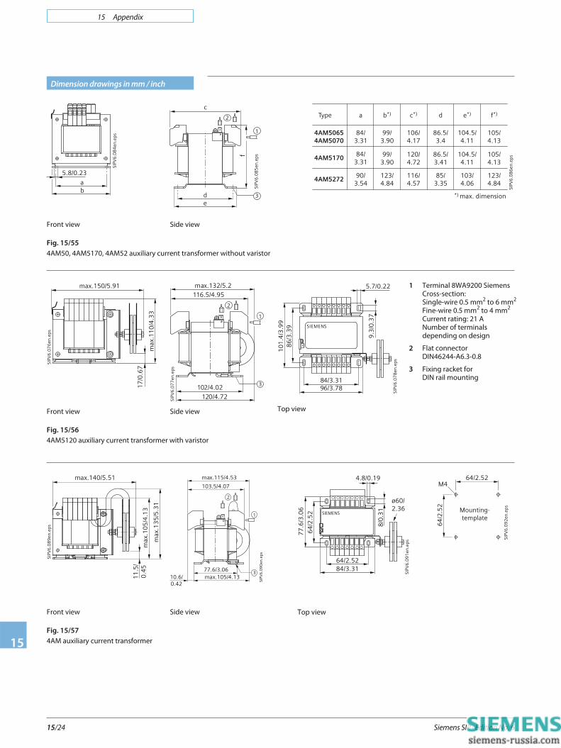
Dimension drawings in mm / inch
c
f
SIPV
6.0
85
en.e
ps
de
1
2
3
Side view
Type
4AM50654AM5070
4AM5170
4AM5272
a
84/3.31
84/3.31
90/3.54
b*)
99/3.90
99/3.90
123/4.84
c*)
106/4.17
120/4.72
116/4.57
d
86.5/3.4
86.5/3.41
85/3.35
e*)
104.5/4.11
104.5/4.11
103/4.06
f*)
*) max. dimension
105/4.13
105/4.13
123/4.84
SIPV
6.0
86
en.e
ps
5.8/0.23
ab
SIPV
6.0
84
en.e
ps
Front view
Fig. 15/55
4AM50, 4AM5170, 4AM52 auxiliary current transformer without varistor
max.132/5.2116.5/4.95
102/4.02120/4.72SI
PV6
.07
7en
.eps
1
2
3
Side view
SIEMENS
9.3
/0.3
7
5.7/0.22
SIPV
6.0
78
en.e
ps96/3.7884/3.31
10
1.4
/3.9
98
6/3
.39
Top view
SIPV
6.0
76
en.e
ps
17
/0.6
7
max.150/5.91
max
.11
0/4
.33
Front view
Fig. 15/56
4AM5120 auxiliary current transformer with varistor
1 Terminal 8WA9200 Siemens
Cross-section:
Single-wire 0.5 mm2
to 6 mm2
Fine-wire 0.5 mm2
to 4 mm2
Current rating: 21 A
Number of terminals
depending on design
2 Flat connector
DIN46244-A6.3-0.8
3 Fixing racket for
DIN rail mounting
SIPV
6.0
90
en.e
ps
max.115/4.53
103.5/4.07
77.6/3.0610.6/0.42
max.105/4.13
2
1
3
Side view
ø60/2.36
SIEMENS
SIPV
6.0
91
en.e
ps
8/0
.31
4.8/0.19
77
.6/3
.06
64
/2.5
2
64/2.5284/3.31
Top view
max.140/5.51
max
.10
5/4
.13
max
.13
5/5
.31
SIPV
6.0
89
en.e
ps
11
.5/
0.4
5
Front view
Fig. 15/57
4AM auxiliary current transformer
64/2.52
Mounting-template
64
/2.5
2
SIPV
6.0
92
en.e
ps
M4

15 Appendix
Siemens SIP · Edition No. 6 15/25
15
Assignment for products
Products applied until now Function Recommended new products
7PA10 Auxiliary relay 7PA26/27
7PA20 Lockout relay 7PA22/23
7PA21 Trip circuit monitoring 7PA30
7RP72 Frequency relay 7RW600
7SD24 Line differential relay 7SD600
7SD510/511 Line differential relay via FO 7SD610
7SD512 Line differential relay via FO 7SD5
7SA500 Distance protection 7SA6, 7SA522
7SA501 Distance protection 7SA6, 7SA522
7SA502 Distance protection 7SA6, 7SA522
7SA510 Distance protection 7SA6, 7SA522
7SA511 Distance protection 7SA6, 7SA522
7SA513 Distance protection 7SA6, 7SA522
7SJ41 Overcurrent relay 7SJ45
7SJ50 Overcurrent relay 7SJ600/602/80
7SJ510 Overcurrent relay 7SJ61
7SJ511 Overcurrent relay 7SJ61
7SJ512 Overcurrent relay 7SJ62
7SJ531 Overcurrent relay 7SJ63
7SK52 Motor protection 7SK80See SIP 3.01SIPROTEC Compact CatalogE50001-K4403-A011-A1-7600
7SN71 Transient earth fault relay 7SN600
7UT512 Transformer differential relay 7UT612
7UT513 Transformer differential relay 7UT613/7UT63
7UM51 Machine protection 7UM61/62
7TS15 Annuciation relay 7TS16
7SS51 Busbar protection 7SS52
7SS13 Busbar protection 7SS60
7VH80/83, 7VH60 High-impedance diff. protection 7SR23 ReyrolleSee www.siemens.com/siprotec
7SV50 BF relay 7SV600
7SV512 Breaker failure relay 7VK61
7VK512 Auto-reclosure undsynchronism check relay
7VK61
7XV72 Test switch 7XV75
7XS50 DIGSI operating program 7XS54

15 Appendix
Siemens SIP · Edition No. 615/26
15
Order No. Index
Order No. Page
E50001 3/6
W73078 9/15
3AX11 5/9
3PP1326 11/64
3PP1336 11/27, 11/64
3RV1611 14/19
3RV1901 14/19
4AM4930 7/14, 14/22
4AM50 5/9, 14/22
4AM5120 9/16, 14/22
4AM5170 14/22
4AM5272 9/16, 14/22
4NC5225 11/64
6MD61 12/5
6MD63 12/12
6MD66 12/26
6XV8100 13/113
7KE6000 13/10, 13/12, 13/114
7PA22 14/6
7PA23 14/7
7PA26 14/10
7PA27 14/11
7PA30 14/12, 14/13
7RW600 11/79
7SA522 6/70
7SA61 6/29
7SA63 6/30
7SA64 6/31
7SD5 7/72
7SD600 7/13
7SD610 7/38
7SJ450 5/9
7SJ460 5/17
7SJ600 5/29
7SJ602 5/49
7SJ61 5/75
7SJ62 5/110
7SJ63 5/149
7SJ64 5/192
7SN600 10/36
7SS52 9/30
7SS60 9/15
7SV600 10/29
7TM7000 9/15
Order No. Page
7TR7100 9/15
7TS16 14/16
7TS7200 9/15
7UM61 11/26
7UM62 11/62
7UT612 8/35
7UT613 8/37
7UT63 8/39
7UW5000 11/69
7VE6110 11/97
7VE6320 11/98
7VK61 10/17
7XP2041 9/15
7XP90 14/6, 14/7, 14/10, 14/11, 14/12, 14/13, 14/16
7XR6004 11/64
7XR6100 11/27, 11/63
7XR9513 7/14, 14/22
7XR9515 7/14, 14/22
7XR9516 7/40, 7/76, 14/22
7XS5400 3/7
7XS5401 3/6
7XS5402 3/6
7XS5403 3/6
7XS5407 3/6
7XS5408 3/6
7XS5410 3/12
7XS5411 3/12
7XS5416 3/12
7XS5460 3/7
7XS5490 3/7
7XS5900 3/7
7XT3300 11/64
7XT3400 11/64
7XT7100 11/64
7XV5100 5/51
7XV5101 13/4
7XV5103 13/7, 13/10, 13/12
7XV5104 13/14
7XV5105 13/16
7XV5450 13/19
7XV5461 13/23, 13/19, 13/31
7XV5550 13/35
7XV5650 13/40
7XV5651 13/40
15 Appendix
Siemens SIP · Edition No. 6 15/27
15
Order No. Page
Order No. Index
7XV5652 13/43
7XV5653 13/47
7XV5654 13/83
7XV5655 13/51, 13/55
7XV5662 13/59, 13/63, 13/6713/71, 13/76, 13/80
7XV5664 13/83
7XV5673 13/92
7XV5700 13/95
7XV5710 13/100
7XV5820 13/108
7XV585 13/111
7XV6010 9/15
7XV6201 14/4
7XV750 14/4
15 Appendix
Siemens SIP · Edition No. 615/28
15
Training
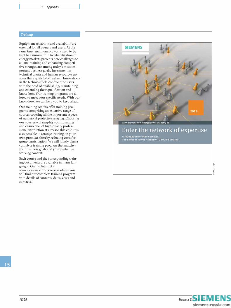
Equipment reliability and availability areessential for all owners and users. At thesame time, maintenance costs need to bekept to a minimum. The liberalization ofenergy markets presents new challenges toall; maintaining and enhancing competi-tive strength are among today’s most im-portant business goals. Investment intechnical plants and human resources en-ables these goals to be realized. Innovationsin the technical field confront the userswith the need of establishing, maintainingand extending their qualification andknow-how. Our training programs are tai-lored to meet your specific needs. With ourknow-how, we can help you to keep ahead.
Our training centers offer training pro-grams comprising an extensive range ofcourses covering all the important aspectsof numerical protective relaying. Choosingour courses will simplify your planningand ensure you of high-quality profes-sional instruction at a reasonable cost. It isalso possible to arrange training on yourown premises thereby reducing costs forgroup participation. We will jointly plan acomplete training program that matchesyour business goals and your particularworking context.
Each course and the corresponding train-ing documents are available in many lan-guages. On the Internet atwww.siemens.com/power-academy youwill find our complete training programwith details of contents, dates, costs andcontacts.
SIPV
6_11
3.tif

15 Appendix
Siemens SIP · Edition No. 6 15/29
15
Books and publications
Siemens Order No.
A19100-L531-B107-X-7600
ISBN 978-3-89578-351-7
Siemens Order No.
A19100-L531-B972-X-7600
ISBN 978-3-89578-318-0
Books on protection
A textbook and standard work in one,these books cover all topics, which have tobe paid attention to for planning, design-ing, configuring and applying differentialand distance protection systems. Thebooks are aimed at students and engineerswho wish to familiarize themselves withthe subject of differential/distance substa-tion protection, as well as the experienceduser, entering the area of numerical differ-ential/distance protection. Furthermore,they serve as a reference guide for solvingapplication problems.
Motor Protection and
IEC Standard Application Brochures
for SIPROTEC Protection Relays
On 76 pages the “Motor protectionbrochure” describes the principles of asyn-chronous and synchronous motors, gives anoverview of relay protection functions formotors and details on protection of low-,medium- and high-power motors.
If you wish to know more about efficientenergy automation in accordance with theIEC 61850 standard, then our “IEC 61850brochure” is the right source to turn to.
Topics covered comprise, among others,switchgear interlocking with IEC 61850GOOSE, reverse interlocking, innovativesolutions for substation control withIEC 61850.
Please contact your Siemens representativefor free copies by indicating the Order No.
Multimedia CD ROMs/DVDs
Useful information on selection and applica-tion for the SIPROTEC protection relays isprovided for the user.
The following subject matters are availableon one DVD:
− SIPROTEC relay features
− SIPROTEC application hints
− Communication based on IEC 61850
− DIGSI Software operating program
− SIGRA Software evaluation of fault records
Computer-based interactive training:Study, practice, check your knowledge
Ask your Siemens representative for theCDs/DVDs free of charge.
Order No.
E50001-K4454-A101-A1-7600
Order No.
E50001-K4455-A101-A2-7600
SIPV
6_11
4.tif
SIPV
6_11
5.tif
LSP2
892.
tif
LSP2
893.
tif
List of available multimedia CD ROMs/DVDs
Title Order No.
SIPROTEC 4 Tutorial E50001-U310-D21-X-7100
LSP2
894.
tif
15 Appendix
Siemens SIP · Edition No. 615/30
15
Legal notice
Indication of conformity
This product complies with the directive of theCouncil of the European Communities onharmonization of the laws of the Member Statesrelating to electromagnetic compability (EMCCouncil Directive 2004/108/EC) and concerning
electrical equipment for use within specified voltage limits (LowVoltage Directive 2006/95/EC).
This conformity has been proved by tests performed according tothe Council Directive in accordance with the generic standardsEN 61000-6-2 and EN 61000-6-4 (for EMC directive) and with thestandard EN 60255-27 (for Low Voltage Directive) by Siemens AG.
The device is designed and manufactured for application in anindustrial environment.
The product conforms with the international standard ofIEC 60255 and the German standard VDE 0435.
Disclaimer of liability
This document has been subjected to rigorous technical review be-fore being published. It is revised at regular intervals, and any modi-fications and amendments are included in the subsequent issues.The content of this document has been compiled for informationpurposes only. Although Siemens AG has made best efforts to keepthe document as precise and up-to-date as possible, Siemens AGshall not assume any liability for defects and damage which resultthrough use of the information contained herein.
This content does not form part of a contract or of business relations;nor does it change these. All obligations of Siemens AG are stated inthe relevant contractual agreements.
Siemens AG reservers the right to revise this document from time totime.
Document version: 06
Release status: 12.2011
Copyright
Copyright © Siemens AG 2012. All rights reserved.
The disclosure, duplication, distribution and editing of thisdocument, or utilization and communication of the contentare not permitted, unless authorized in writing. All rights,including rights created by patent grant or registration ofa utility model or a design, are reserved.
Registered trademarks
SIPROTEC and DIGSI are registered trademarks of Siemens AG.Any unauthorized use is illegal. All other designations in thisdocument can be trademarks whose use by third parties for theirown purposes can infringe the rights of the owner.
For more information, please contact
our Customer Support Center.
Tel.: +49 180 524 84 37
Fax: +49 180 524 24 71
(Charges depending on provider)
E-mail: [email protected]
Order No.: E50001-K4400-A101-A6-7600
Printed in Germany
Dispo 06200, c4bs 7442
KG 12.11 1.0 878 EN
3600 / 35522 WÜ
Published by and copyright © 2012:
Siemens AG
Infrastructure & Cities Sector
Smart Grid Division
Humboldtstr. 59
90459 Nuremberg, Germany
Siemens AG
Infrastructure & Cities Sector
Smart Grid Division
Energy Automation
Humboldtstr. 59
90459 Nuremberg, Germany
www.siemens.com/protection
Printed on elementary chlorine-free bleached paper.
All rights reserved.
If not stated otherwise on the individual pages of this
catalog, we reserve the r ight to include modifications,
especially regarding the stated values, dimensions
and weights. Drawings are not binding.
All product designations used are trademarks or
product names of Siemens AG or other suppliers.
If not stated otherwise, all dimensions in this
catalog are given in mm.
Subject to change without prior notice.
The information in this document contains general
descriptions of the technical options available, which
may not apply in all cases. The required technical
options should therefore be specified in the contract.


