The Intermedical® U500 Urine Analyzer is a semi-automated reflectance photometerthat analyzes the intensity and color of light reflected from the reagent areas of aurinalysis reagent strip. The analyzer throughput is 500 tests per hour and themeasuring cycle is 7 seconds per test. The analyzer stores up to 2,000 patientrecords and prints the results in Conventional, SI, or Arbitrary units using an integratedinternal or external printer.
The Intermedical® U500 Urine Analyzer features automatic calibration, self-testcapability and touch screen LCD for easy operation. A light emitting diode (LED)detects the presence of the strip, provides incubation timing, automatically transportsthe strip for analysis and deposits the strip into an internal waste tray. The combinedstrip platform and waste tray allow for one step easy cleaning. An optional barcodereader records patient identification (ID). Records can be transferred to a computerfor further analysis. The simple user-friendly software is designed to minimize usertraining and maximize analyzer functionality.
Note: In this user guide, analyzer parts or components are referred to inbold, while display items on the screen are identified in bolditalics.
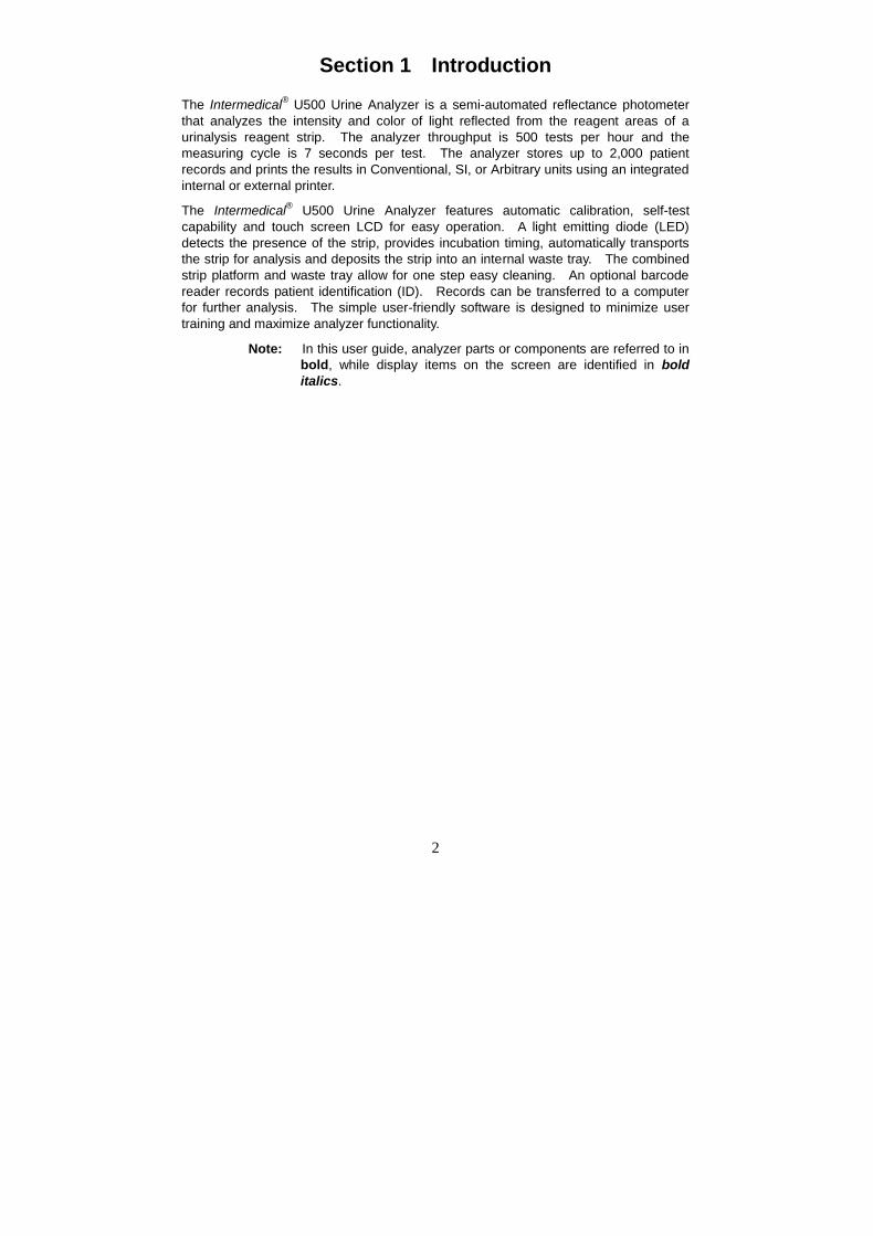
7. Printer Paper Roll Container 15. Strip Platform and Waste Tray
8. Printer release Lever
4
Section 3 Initial Startup
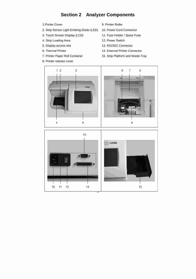
Inspect the carton, analyzer and accessories for visible damage. Contact your localdistributor if any visible damage exists. Remove the analyzer and other packagingcontents from the carton. The analyzer consists of the following components.
Component ListNo. Components Quantity1 U500 Urine Analyzer 12 Strip Platform and Waste Tray 13 Printer Paper Rolls 24 Fuses (2.0 A) 25 Power Cord 16 Serial Splitter Cable (Optional) 17 Data Transfer Cable
Place the analyzer on a level surface. Allow 80 x 50 cm on all sides of the analyzer foraccess.
Load Printer PaperLoad printer paper following instructions in Section 8
Install External Printer (Optional)Plug the 25 pin printer cable from the compatible external printer into the ExternalPrinter Connector in the back of the analyzer.
Enable External Data TransIntermedical (Optional)Plug a compatible RS232C cable from a computer to the RS232C Connector in theback of the analyzer.
Data records are automatically sent to the computer at the same time as printing to theprinter, where they can be received by suitable software installed on the computer. Ifthe computer with software is not connected to the analyzer prior to performing a test,the operator must manually export each record one at a time.
5
Install Barcode Reader (Optional)Plug the RS232C cable from the barcode reader into the RS232C Connector in theback of the analyzer using the cable supplied with the Barcode reader.
Refer to Appendix 3 Barcode Reader for specifications and compatibilities.
If both the optional Barcode Reader and external data transIntermedical capability areused at the same time, use the serial splitter cable to connect both external computerand barcode reader to the analyzer RS232C connector.
Turn on AnalyzerConnect the power cord to the analyzer power connector, then into a suitable poweroutlet.
Press the Power Switch located on the back panel to turn the analyzer on and initiatethe Automatic Self-Test.
If the Automatic Self-Inspection passes, the Initial Screen below will be displayedindicating the analyzer is functioning properly.
The analyzer is now ready for operation with configuration defaults. Please refer toSection 4 for Analyzer Setup and Configuration, Section 5 for full analyzer operatingdetails. If the Automatic Self-Inspection fails, a “Failed” Screen will be displayedindicating the source of the failure. Refer to Troubleshooting Table in Section 10 tocorrect the failure.
6
Section 4 Analyzer Setup
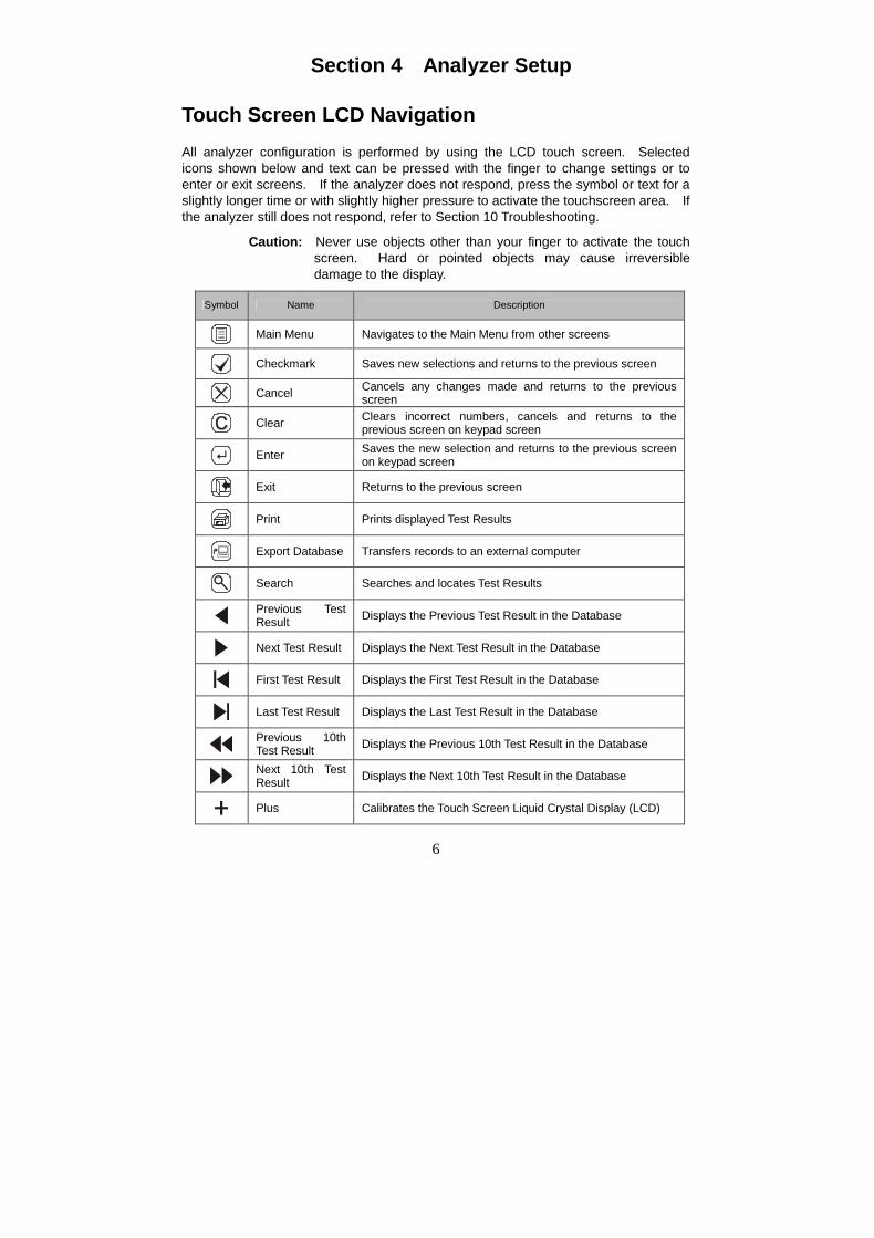
Touch Screen LCD NavigationAll analyzer configuration is performed by using the LCD touch screen. Selectedicons shown below and text can be pressed with the finger to change settings or toenter or exit screens. If the analyzer does not respond, press the symbol or text for aslightly longer time or with slightly higher pressure to activate the touchscreen area. Ifthe analyzer still does not respond, refer to Section 10 Troubleshooting.
Caution: Never use objects other than your finger to activate the touchscreen. Hard or pointed objects may cause irreversibledamage to the display.
Symbol Name Description
Main Menu Navigates to the Main Menu from other screens
Checkmark Saves new selections and returns to the previous screen
Cancel Cancels any changes made and returns to the previousscreen
Clear Clears incorrect numbers, cancels and returns to theprevious screen on keypad screen
Enter Saves the new selection and returns to the previous screenon keypad screen
Exit Returns to the previous screen
Print Prints displayed Test Results
Export Database Transfers records to an external computer
Search Searches and locates Test Results
Previous TestResult Displays the Previous Test Result in the Database
Next Test Result Displays the Next Test Result in the Database
First Test Result Displays the First Test Result in the Database
Last Test Result Displays the Last Test Result in the Database
Previous 10thTest Result Displays the Previous 10th Test Result in the Database
Next 10th TestResult Displays the Next 10th Test Result in the Database
Plus Calibrates the Touch Screen Liquid Crystal Display (LCD)
7
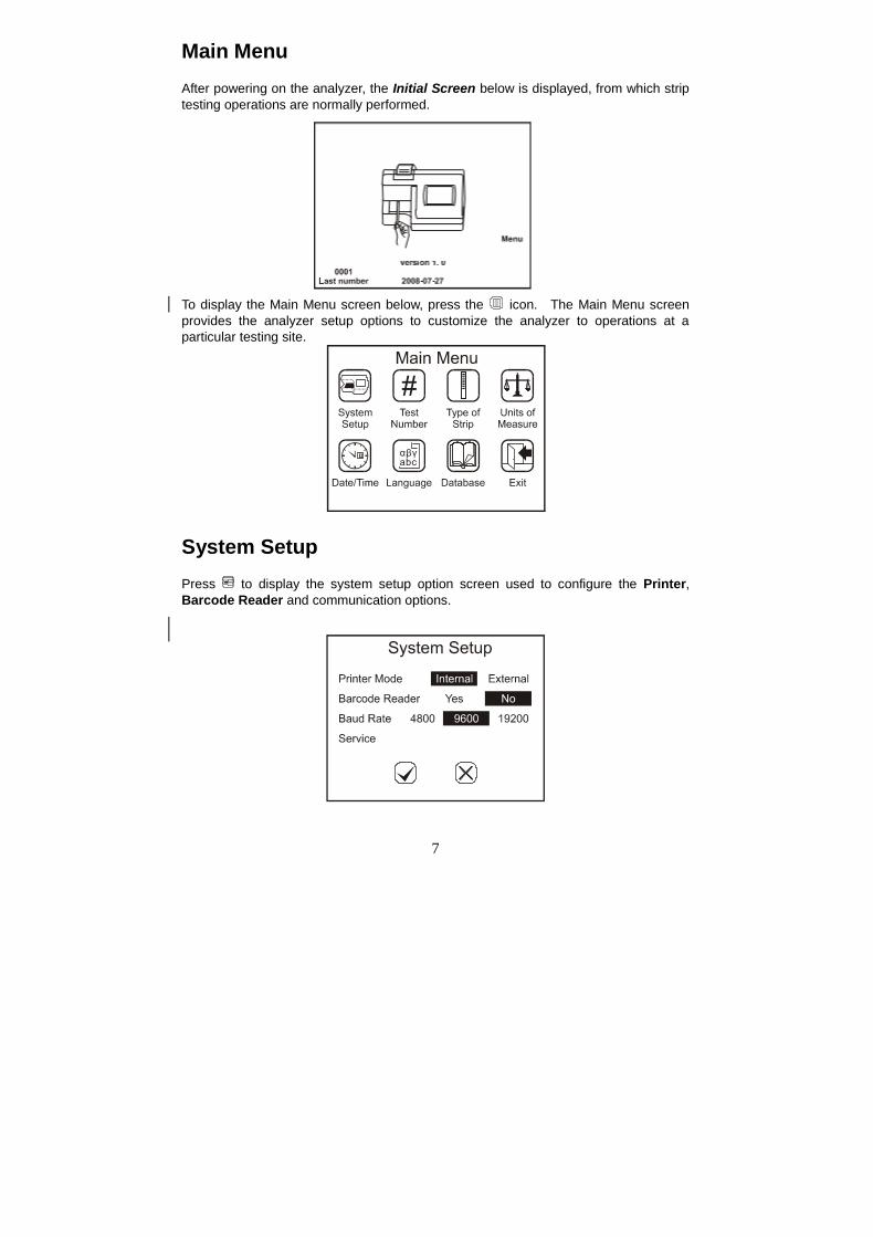
Main MenuAfter powering on the analyzer, the Initial Screen below is displayed, from which striptesting operations are normally performed.
To display the Main Menu screen below, press the icon. The Main Menu screenprovides the analyzer setup options to customize the analyzer to operations at aparticular testing site.
System SetupPress to display the system setup option screen used to configure the Printer,Barcode Reader and communication options.
8
Once all selections are complete, press to save the selections and show the MainMenu screen.
Press to cancel all changes and show the Main Menu screen.
Printer ModePress Printer Mode to cycle the printer mode through the Internal and External settings.The selected mode will be highlighted.
Internal setting will print all test printouts to the Internal Printer.
External setting will print all test printouts to the External Printer if it is available.
Barcode ReaderPress Barcode Reader to highlight Yes if the optional Barcode Reader is installed.Screens will be modified to accept barcoded sample IDs to be read with the optionalBarcode Reader.
If the Barcode Reader is not installed, press Barcode Reader to highlight No.
Baud RateThe Baud Rate is the communication speed for the RS232C port, used with theBarcode Reader or external computer. All devices connected to the RS232C portmust be configured for the same baud rate, otherwise they will not work. The defaultbaud rate for the Barcode Reader is 9600.
Press Baud Rate to cycle the highlighted baud rate through the options. Select thedesired baud rate and leave it highlighted.
ServicePress Service to show the Password entry screen. Enter the password to performany service related operations. Press to Clear the last number entered. Press
to accept the number entered and enter the service screens.
Note: Service mode is not normally accessible as part of analyzeroperation. Servicing the analyzer should be performed by aprofessional engineer or technician only. Contact your localdistributor for the Service password if needed.
Test NumberPress under to display the menu below for configuring test numbers and operatingmode. When configuration is complete, press to accept the change and return tothe Main Menu screen. Press to return to the Main Menu screen withoutchanging any parameters.
9
Select ModePress Select Mode to cycle the selection through the three available modes.
Routine Test
Used for normal urine testing. The test number ranges from 00001 to 09999,always with a leading 0. It resets to 00001 every day automatically if Auto Reset0001 is Yes.
Stat Test
Used for emergency urine testing. The test number ranges from 10001 to 19999,always with a leading 1. It resets to 10001 each day automatically if Auto Reset0001 is Yes.
QC Test
Used to test positive/negative controls. The test number ranges from 20001 to29999 and resets to 20001 every day automatically if Auto Reset 0001 is Yes.
Note: Ensure QC Test mode is used for testing positive and negativecontrols so test data can be easily searched for and identified.
Enter New No.The current Test Number will be displayed next to Enter New No. Press Enter NewNo. to display the Numeric Keypad to change the Test Number to a new sequence.
10
Enter up to 4 digits by touching the Numeric Pads on the touchscreen. Press toClear the last number entered. Press to accept the number entered and return tothe previous screen.
Note: The highest test number is X9999. After the test number reachesX9999 it will revert to X0001. X indicates the leading 0, 1 or 2depending on test mode.
Warning: Maximum number of test results is 2000. After 2000 test resultsare stored in memory, new test results will begin overwriting(erasing) the oldest test results stored in memory.
Auto Reset 0001Press Auto Reset 0001 to cycle to Yes or No. If Yes, the test number will reset to00001, 10001 or 20001 for Routine, Stat or QC modes when the power is switched offand then on again. If No the test number is unaffected by power cycling.
Clear All DataPress Clear All Data to show a confirmation screen confirming you want to clear allpatient and sample result data.
Press to continue to delete all data. After deleting data, the Test Number will resetto 00001, 10001 or 20001 depending on the Test Mode. Press to return to theTest Number screen without deleting data.
Type of StripFrom the Main Menu, press to change the strip type. The Type of Strip currentlyselected will be shown highlighted on the screen. Each strip type name defines thenumber of test parameters per strip, e.g. A08 is an 8 parameter strip.
Refer to Appendix 2 for a detailed list of parameters.
Note: Ensure the type of strip selected corresponds with the strip to beused. If not, it will be detected and an error message will bedisplayed.
11
Press the type of stip you will be using for testing, highlighting the proper strip type.Once the proper strip type is selected, press to accept the change and return to theMain Menu screen. Press to return to the Main Menu screen without changingstrip type.
Units of MeasureFrom the Main Menu, press to select Units of Measure using the screen below.Press either Conventional or SI to select either of these units on the touchscreen.The selection will be highlighted.
Note: Arbitrary results will be printed automatically regardless of the unitsetting selected.
Press to accept the changes and return to the Main Menu or press to return tothe Main Menu without any changes.
Date/TimeFrom the Main Menu, press to change Date or Time settings. The Date/Timescreen will be shown.
To change any of the Date or Time settings, press the appropriate display area, eitherthe name or associated number. This will bring up the numeric keypad for entering the
12
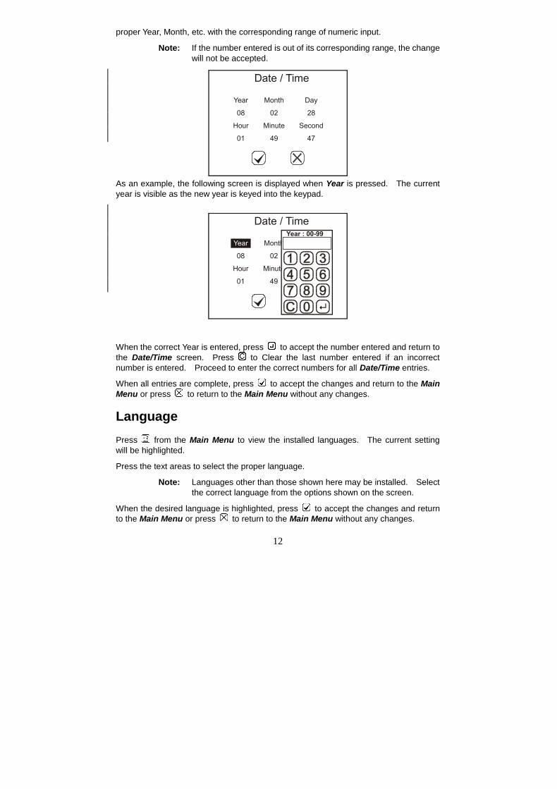
proper Year, Month, etc. with the corresponding range of numeric input.
Note: If the number entered is out of its corresponding range, the changewill not be accepted.
As an example, the following screen is displayed when Year is pressed. The currentyear is visible as the new year is keyed into the keypad.
When the correct Year is entered, press to accept the number entered and return tothe Date/Time screen. Press to Clear the last number entered if an incorrectnumber is entered. Proceed to enter the correct numbers for all Date/Time entries.
When all entries are complete, press to accept the changes and return to the MainMenu or press to return to the Main Menu without any changes.
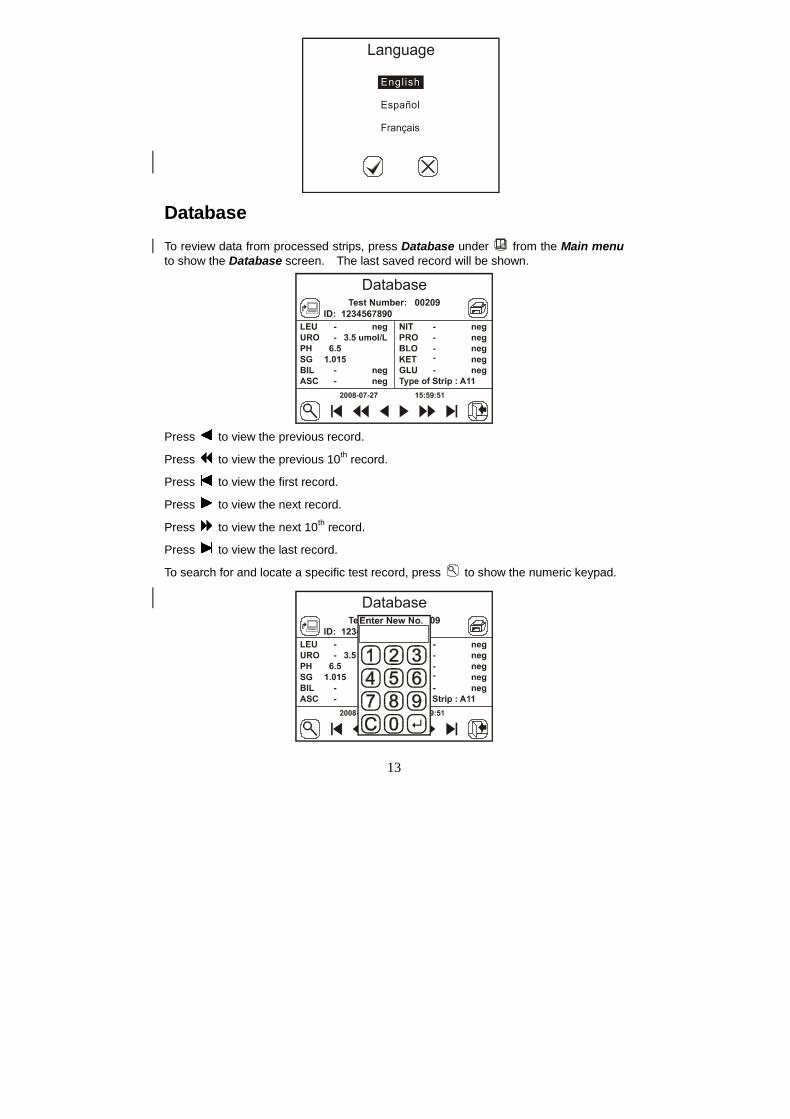
LanguagePress from the Main Menu to view the installed languages. The current settingwill be highlighted.
Press the text areas to select the proper language.
Note: Languages other than those shown here may be installed. Selectthe correct language from the options shown on the screen.
When the desired language is highlighted, press to accept the changes and returnto the Main Menu or press to return to the Main Menu without any changes.
13
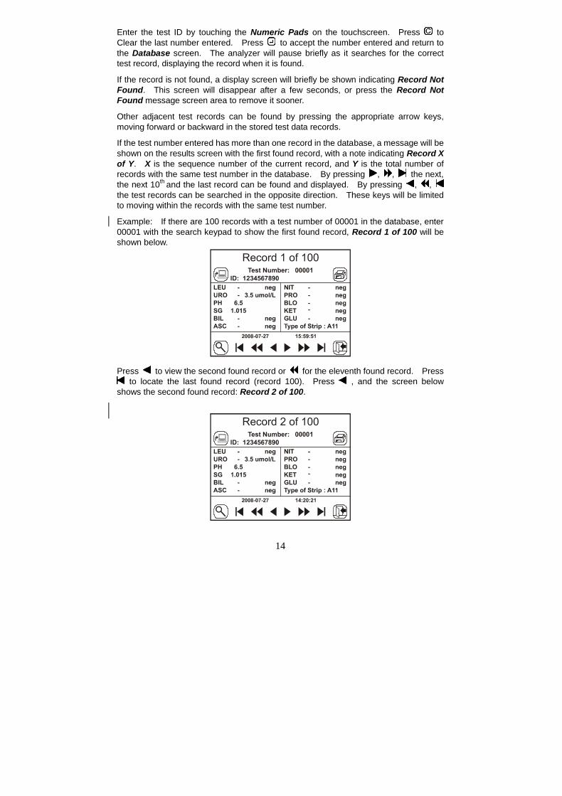
DatabaseTo review data from processed strips, press Database under from the Main menuto show the Database screen. The last saved record will be shown.
Press to view the previous record.
Press to view the previous 10th record.
Press to view the first record.
Press to view the next record.
Press to view the next 10th record.
Press to view the last record.
To search for and locate a specific test record, press to show the numeric keypad.
14
Enter the test ID by touching the Numeric Pads on the touchscreen. Press toClear the last number entered. Press to accept the number entered and return tothe Database screen. The analyzer will pause briefly as it searches for the correcttest record, displaying the record when it is found.
If the record is not found, a display screen will briefly be shown indicating Record NotFound. This screen will disappear after a few seconds, or press the Record NotFound message screen area to remove it sooner.
Other adjacent test records can be found by pressing the appropriate arrow keys,moving forward or backward in the stored test data records.
If the test number entered has more than one record in the database, a message will beshown on the results screen with the first found record, with a note indicating Record Xof Y. X is the sequence number of the current record, and Y is the total number ofrecords with the same test number in the database. By pressing , , the next,the next 10th and the last record can be found and displayed. By pressing , ,the test records can be searched in the opposite direction. These keys will be limitedto moving within the records with the same test number.
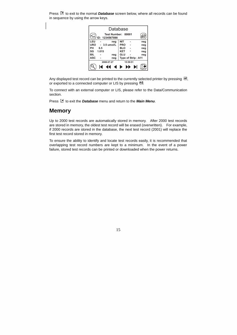
Example: If there are 100 records with a test number of 00001 in the database, enter00001 with the search keypad to show the first found record, Record 1 of 100 will beshown below.
Press to view the second found record or for the eleventh found record. Press to locate the last found record (record 100). Press , and the screen below
shows the second found record: Record 2 of 100.
15
Press to exit to the normal Database screen below, where all records can be foundin sequence by using the arrow keys.
Any displayed test record can be printed to the currently selected printer by pressing ,or exported to a connected computer or LIS by pressing .
To connect with an external computer or LIS, please refer to the Data/Communicationsection.
Press to exit the Database menu and return to the Main Menu.
MemoryUp to 2000 test records are automatically stored in memory. After 2000 test recordsare stored in memory, the oldest test record will be erased (overwritten). For example,if 2000 records are stored in the database, the next test record (2001) will replace thefirst test record stored in memory.
To ensure the ability to identify and locate test records easily, it is recommended thatoverlapping test record numbers are kept to a minimum. In the event of a powerfailure, stored test records can be printed or downloaded when the power returns.
16
Section 5 Analyzer Operation
Operation without Barcode ReaderEnsure the analyzer is set up and operating as described in Section 3 Initial Startup,and analyzer parameters are configured properly as described in Section 4 AnalyzerSetup. Turn the power switch located at the back panel of the analyzer on. Theinitial screen will be displayed indicating the analyzer is ready to begin testing strips,with an animated test strip icon indicating the analyzer is ready to accept strips fortesting.
Sample/Strip PreparationAllow the strip, urine specimen, and/or controls to reach room temperature at 15-30ºC(59-86ºF) prior to testing.
Note: Use strips of the same brand as the analyzer for proper functionand accurate results.
Remove the strips from the closed canister and use them as soon as possible. Closethe canister tightly immediately after removing the strips.
Strip Processing and TestUsing a new strip, completely immerse the reagent areas of the strip in fresh,well-mixed urine for about 2 seconds. Immediately remove the strip to avoiddissolving the reagents.
Note: Immerse all strip pads completely into sample, or a Dry Strip errormay occur.
17
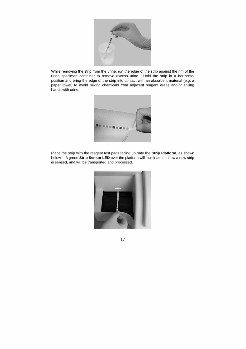
While removing the strip from the urine, run the edge of the strip against the rim of theurine specimen container to remove excess urine. Hold the strip in a horizontalposition and bring the edge of the strip into contact with an absorbent material (e.g. apaper towel) to avoid mixing chemicals from adjacent reagent areas and/or soilinghands with urine.
Place the strip with the reagent test pads facing up onto the Strip Platform, as shownbelow. A green Strip Sensor LED over the platform will illuminate to show a new stripis sensed, and will be transported and processed.
18
Note: Ensure the strip is placed properly onto the Strip Platform.Improper strip placement may cause the Strip Transport tomalfunction, resulting in inaccurate readings. Incorrect stripplacement may result in a blank test result, displaying only the date,time, and ID number.
The strip will be processed sequentially through several internal incubation locations,taking 60 seconds total from accepting a strip at the loading area to displaying, storingand printing test results. Results will be automatically printed only if the InternalPrinter is selected. Waste strips will be deposited into the Waste Tray automaticallyby the strip transport system.
The analyzer performs an automatic calibration each time a test is run. Results will bedisplayed on the screen and recorded in memory automatically. Any abnormal resultswill be highlighted on the screen and flagged on the print out.
Warning: Do not place foreign objects other than strips onto the Strip
Platform.
After the first strip is transported into the analyzer and the Strip Sensor LED turns off,repeat the above process to test additional urine specimens. A new specimen can beadded approximately every 7 seconds.
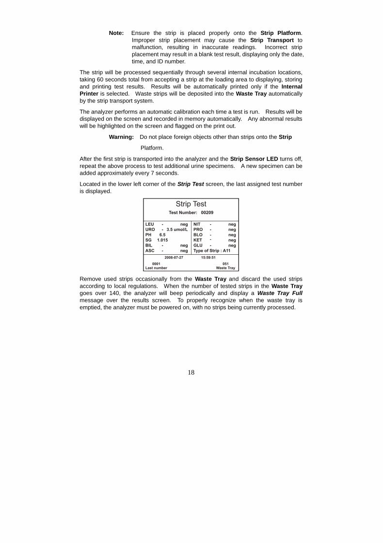
Located in the lower left corner of the Strip Test screen, the last assigned test numberis displayed.
Remove used strips occasionally from the Waste Tray and discard the used stripsaccording to local regulations. When the number of tested strips in the Waste Traygoes over 140, the analyzer will beep periodically and display a Waste Tray Fullmessage over the results screen. To properly recognize when the waste tray isemptied, the analyzer must be powered on, with no strips being currently processed.
19
The analyzer will process the remaining strips on the Strip Platform, but will processno additional strips until the Waste Tray is emptied. Once the final strips areprocessed, a blinking Waste Tray Full message on the Initial Screen along with alarge X over the Waste Tray area will be displayed as shown below.
Remove the Strip Platform and Waste Tray assembly and empty processed strips asnecessary.
Caution: Do not remove the Waste Tray when the analyzer is processingstrips. The strip transport mechanism could be damaged if itattempts to move strips with the Waste Tray partially removed.
Perform daily cleaning when analysis is completed for the day. Refer to Section 8Maintenance.
20
Operation with Barcode ReaderEnsure the analyzer is set up and operating as described in Section 3 Initial Startup,and analyzer parameters are configured properly as described in Section 4 AnalyzerSetup, with Barcode Reader set to Yes. Turn the power switch located at the backpanel of the analyzer on. The initial screen will be displayed indicating the analyzer isready to begin testing strips, with an animated test strip icon indicating the analyzer isready to accept strips for testing.
Sample/Strip PreparationSample and strip preparation are identical to operation without Barcode Reader.Please refer to previous section for strip processing.
Scan Barcode IDsHolding the barcode reader over the barcode on the specimen container, press theScan button on the Barcode Reader. A red illuminated line will appear over thebarcode to be read. Move the barcode reader to align the red line over the barcode,and position it until the barcode reader beeps, indicating the barcode has beenscanned. The barcode entry screen will be shown, displaying the scanned barcodes.
Up to 100 barcodes can be entered at the same time. Once entered, the samplesmust be run in sequence scanned.
Alternatively, each sample ID can be scanned at the same time as sample processing,one at a time. The analyzer will not process or accept a new strip unless it has abarcode for a strip placed on the Strip Platform.
21
New samples can be scanned and processed at any time prior to completion of stripscurrently being processed.
Note: Do not change Barcode reader or Test number settings before allbarcodes have been processed, otherwise remaining barcodesmay be deleted.
22
Section 6 Data/Communication
The analyzer is equipped with two connectors for external data tranIntermedicalpurposes. The largest connector is a 25 pin connector dedicated to an optionalexternal printer. A standard RS232C connector is available for connecting to anexternal computer and to the optional Barcode Reader. If both Barcode Reader andexternal computer are used at the same time, the baud rates for the analyzer, BarcodeReader and external computer ports must be configured to the same baud rate toallow communication between all devices connected to the RS232C connector. A “Y”serial splitter cable, provided with the optional Barcode Reader must be used toconnect both Barcode Reader and external computer to the RS232C connector at thesame time.
For data transIntermedical to an external computer, the analyzer requires an RS232CCable and appropriate (optional) communication software, such as Hyperterminal, toconnect with a computer and export the database.
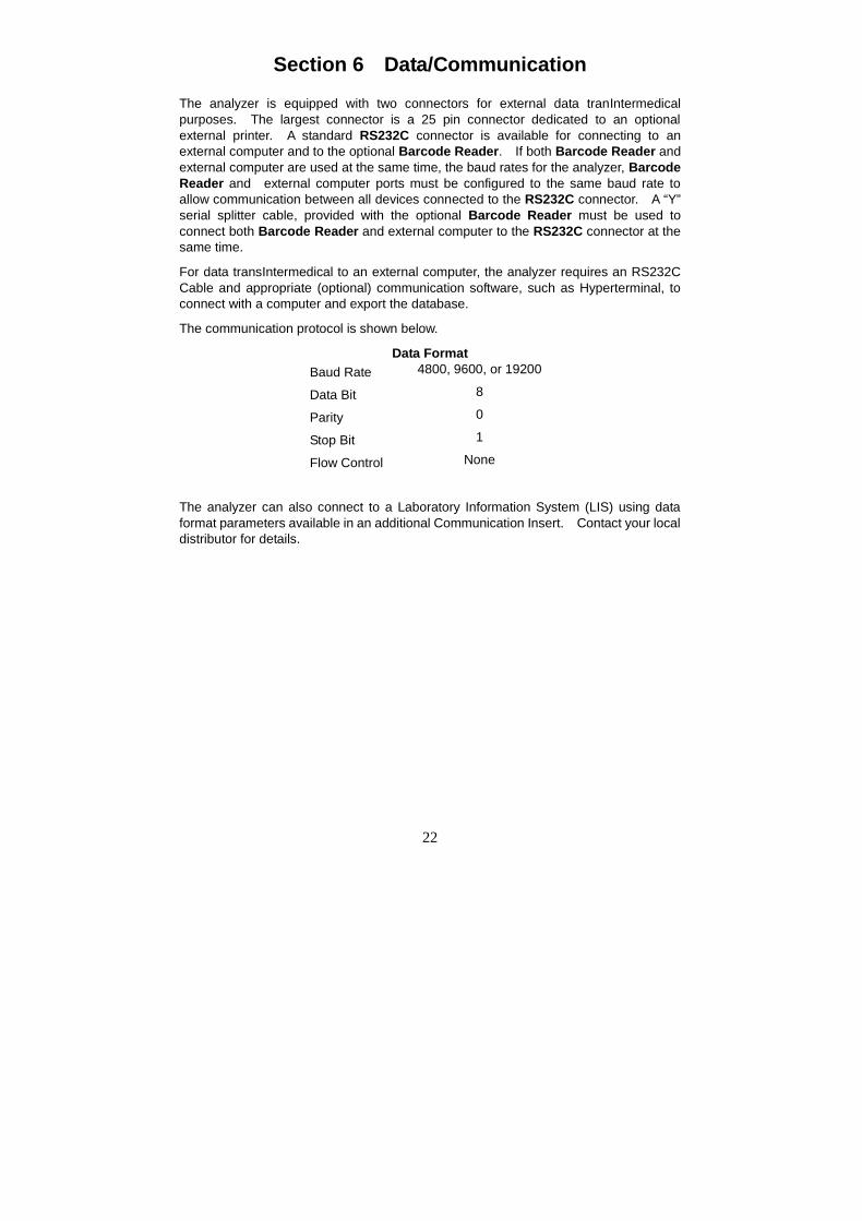
The communication protocol is shown below.
Data FormatBaud Rate 4800, 9600, or 19200
Data Bit 8
Parity 0
Stop Bit 1
Flow Control None
The analyzer can also connect to a Laboratory Information System (LIS) using dataformat parameters available in an additional Communication Insert. Contact your localdistributor for details.
23
Section 7 Quality Control
Each lab should develop and use its own standards and procedures for performance.Test known positive and negative specimen controls at each of the following events:
If the QC tests do not provide expected results, perform the following checks:
Each new day of testing
A new canister of strips is opened
A new operator uses the analyzer
Test results seem inaccurate
If the QC tests do not provide expected results, perform the following checks:
Ensure the strips used are not past their expiration date.
Ensure strips are fresh from a new canister.
Ensure the controls are not past their expiration date.
Repeat the test to ensure no errors were made during the test.
If QC testing still does not provide expected results, contact your local
distributor.
24
Section 8 Maintenance
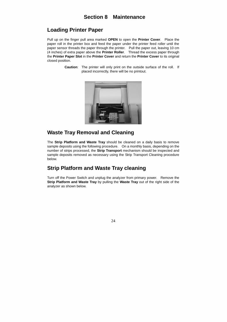
Loading Printer PaperPull up on the finger pull area marked OPEN to open the Printer Cover. Place thepaper roll in the printer box and feed the paper under the printer feed roller until thepaper sensor threads the paper through the printer. Pull the paper out, leaving 10 cm(4 inches) of extra paper above the Printer Roller. Thread the excess paper throughthe Printer Paper Slot in the Printer Cover and return the Printer Cover to its originalclosed position.
Caution: The printer will only print on the outside surface of the roll. Ifplaced incorrectly, there will be no printout.
Waste Tray Removal and CleaningThe Strip Platform and Waste Tray should be cleaned on a daily basis to removesample deposits using the following procedure. On a monthly basis, depending on thenumber of strips processed, the Strip Transport mechanism should be inspected andsample deposits removed as necessary using the Strip Transport Cleaning procedurebelow.
Strip Platform and Waste Tray cleaningTurn off the Power Switch and unplug the analyzer from primary power. Remove theStrip Platform and Waste Tray by pulling the Waste Tray out of the right side of theanalyzer as shown below.
25
Clean the Strip Platform and Waste Tray using a cotton swab or cotton balldampened with distilled water. Dry with a clean, dry cotton ball. With Strip Platformand Waste Tray removed, clean any remaining sample deposits from the strip loadingarea under the Strip Platform using a cotton swab or cotton ball dampened withdistilled water. Take care to prevent any fluids from dripping into the transportmechanism. Dry with a clean, dry cotton ball.
Strip Transport CleaningTurn off the Power Switch and unplug the analyzer from primary power.
Remove the Strip Platform and Waste Tray by pulling the Waste Tray out of the rightside of the analyzer as shown above.
Raise the hinged analyzer Display Panel by placing a finger under the DisplayAccess Slot and pull up on the display. The display will rotate up, allowing access tothe middle of the strip transport area and optical assembly, shown below.
Push the Optical Assembly towards the back of the analyzer to allow enough spacefor cleaning.
26
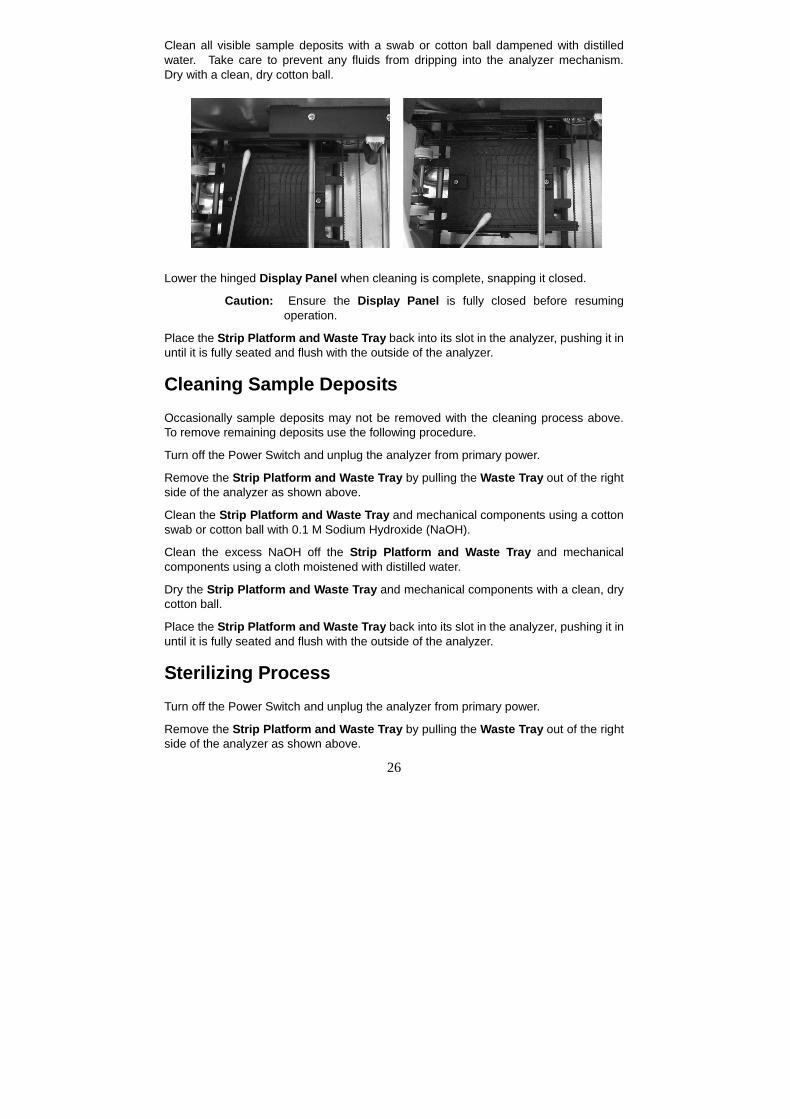
Clean all visible sample deposits with a swab or cotton ball dampened with distilledwater. Take care to prevent any fluids from dripping into the analyzer mechanism.Dry with a clean, dry cotton ball.
Lower the hinged Display Panel when cleaning is complete, snapping it closed.
Caution: Ensure the Display Panel is fully closed before resumingoperation.
Place the Strip Platform and Waste Tray back into its slot in the analyzer, pushing it inuntil it is fully seated and flush with the outside of the analyzer.
Cleaning Sample DepositsOccasionally sample deposits may not be removed with the cleaning process above.To remove remaining deposits use the following procedure.
Turn off the Power Switch and unplug the analyzer from primary power.
Remove the Strip Platform and Waste Tray by pulling the Waste Tray out of the rightside of the analyzer as shown above.
Clean the Strip Platform and Waste Tray and mechanical components using a cottonswab or cotton ball with 0.1 M Sodium Hydroxide (NaOH).
Clean the excess NaOH off the Strip Platform and Waste Tray and mechanicalcomponents using a cloth moistened with distilled water.
Dry the Strip Platform and Waste Tray and mechanical components with a clean, drycotton ball.
Place the Strip Platform and Waste Tray back into its slot in the analyzer, pushing it inuntil it is fully seated and flush with the outside of the analyzer.
Sterilizing ProcessTurn off the Power Switch and unplug the analyzer from primary power.
Remove the Strip Platform and Waste Tray by pulling the Waste Tray out of the rightside of the analyzer as shown above.
27
Clean the Strip Platform and Waste Tray using a cotton swab or cotton ball with oneof the following sterilizing solutions:
1. 2% Glutaraldehyde (sufficient density): Refer to detailed instructions on theproduct label.
2. 0.05% Sodium Hypochlorite Solution: Add 1 mL 5% Sodium Hypochloriteinto 99 mL distilled water, or prepare a 1:100 dilution ratio with appropriatefinal volume.
3. Isopropyl alcohol (70-80%).
Pour the sterilizing solution into a narrow vessel 10 cm (4 inches) high.
Soak the Strip Platform and Waste Tray in the sterilizing solution for 10 minutes.
Take the Strip Platform and Waste Tray out, clean and dry it.
Place the Strip Platform and Waste Tray back into its slot in the analyzer, pushing it inuntil it is fully seated and flush with the outside of the analyzer.
Fuse ReplacementTurn off the Power Switch and unplug the Power Cord from the Power Socket in theback of the analyzer.
Remove the Fuse Cover from the back of the analyzer.
Remove the Fuse and replace with a new Fuse.
Return the Fuse Cover to the original position, and then plug in the Power Cord into thePower Socket in the back of the analyzer.
Touch Screen LCD CalibrationTurn the analyzer Power Switch off, then on.
Prior to the Initial Screen being shown, press anywhere on Touch Screen LCD. TheTouch Screen Calibration screen will be displayed, shown below.
Remove finger from the Touch Screen LCD, a + will be shown in the center of thescreen.
Press the + displayed on the center of the screen to begin calibration.
The + will move to the upper right area of the screen. Press the + displayed on theupper right of the screen.
The + will move to the lower right area of the screen. Again, press the + press the +on the screen.
Repeat this process when the + is displayed in the lower left and upper left area of thescreen. This process calibrates the touchscreen so the analyzer can interpret whichareas are being touched during operation.
28
Note: When touching the screen during the calibration process, ensurethe finger is placed directly over the + sign. If you do not, thetouchscreen may be improperly calibrated and unable to respondproperly to touchscreen input.
29
Section 9 Precautions
Observe the precautions listed below to ensure accurate results and proper operationof the analyzer.
The protection provided by the equipment may be impaired if used in a manner notdefined in this user guide.
Connect to a power connection which contains a working grounding plug.
Wear gloves to avoid contact with potentially hazardous biological samples duringprocessing strips, or analyzer components.
The Analyzer is an electronic laboratory analyzer and must be handled properly foraccurate and reliable results.
Read and follow the Instruction Manual before operating the analyzer.
Turn the Power Switch off and unplug the Power Cord before performingmaintenance or service on the analyzer.
Avoid storing or operating the analyzer in direct sunlight, excessive temperature orhumidity, corrosive gas, strong electromagnetic interference or vibration. Refer toUrine Analyzer Specifications in Appendix 1 for operating condition requirements.
Never place anything on the Strip Platform to avoid collisions when the StripPlatform automatically advances the strip into the analyzer.
Keep the analyzer clean and wipe it down frequently with a soft, clean, dry cloth.
Do not remove the Strip Platform and Waste Tray when strips are beingprocessed
Do not clean the analyzer with substances such as gasoline, paint thinner,benzene compounds or other organic solvents to avoid any damage to the StripPlatform or other components.
Do not wash the Touch Screen Liquid Crystal Display with water. To clean it,lightly wipe it with a clean, soft and dry rag or paper towel.
Do not touch the Touch Screen Liquid Crystal Display with any hard objects. Useonly your finger.
The Strip Platform must be kept clean. Wipe down using fresh water daily.Refer to Section 8 Maintenance.
Follow proper precautions and all local regulations when disposing of the analyzerand used accessories.
Do not use the analyzer or strips outside of the operating temperature ranges listedbelow to ensure accuracy of test results:
Analyzer: 0-40ºC (32-104ºF)
Strips: 15-30ºC (59-86ºF)
30
Section 10 Troubleshooting
Problem SolutionsNo display on screen Ensure power is connected to the analyzer.
Ensure Power Switch is turned onExamine the Fuse on the back of the analyzer todetermine if it is damaged. Replace it if necessary.Refer to Fuse Replacement in this section.
Fuse is damaged Turn off the Power Switch,Disconnect the power cord.Replace the damaged fuse with a new 2.0 A fuse.Refer to Fuse Replacement in this section.
Internal Printer does not work Ensure Printer Paper Roll is installed properly.Refer to Section 6, Load Printer Paper.Ensure Printer Mode is set to Internal.Refer to Section 4 Analyzer Setup.
Touch Screen LCD does not respondcorrectly
Press the Symbol or Text for a slightly longer time orslide your finger across the screen.Turn the Power Switch off and on to perform a TouchScreen Calibration.Refer to Touch Screen LCD Calibration in this section.
Electronic System Test failed Turn the Power Switch off and on.Examine the Fuse on the back of the analyzer todetermine if it is damaged. Replace if necessary.Refer to Fuse Replacement in this section.Ensure the Power Cable is plugged correctly and is notloose or damaged.
Mechanism System Test failed Remove any obstacles in the path of the Strip PlatformDo not touch the Strip Platform when it is movingTurn the Power Switch off and on to perform AutomaticSelf-Inspection. Refer to Operating Instructions inSection 5.
Printer Paper Empty Error
Ensure the Printer Paper Roll is installed correctly.Refer to Section 6 Load Printer Paper.
Strip Platform Removal Error
Install the Strip Platform and Waste Tray into theanalyzer completely, flush with outside housing wall.Refer to Waste Tray Removal, Cleaning and Emptyingin Section 8.
31
Waste Tray Full Error
Remove used strips from the Waste Tray. Discardused strips according to local regulations. Refer toSection 8.Waste Tray Removal, Cleaning and Emptying.
Barcode Reader does not work Ensure the Barcode Reader is fully connected to theanalyzer and connector screws are tightened.Ensure Barcode Reader setting is YesRefer to Section 4 Analyzer Setup
Barcode unreadable Ensure the barcode is compatible with the BarcodeReader.
Contact your local distributor to receive additional technical support if you are unable toresolve the problems.
32
Appendix 1 Urine Analyzer Specifications
Feature SpecificationsMethodology Reflectance PhotometerDetection Photosensitive DiodeThroughput 500 tests/hourMeasuring Cycle 7 seconds/testMemory 2,000 ResultsStrip Incubation Time 1 minuteWavelength 525 nm and 635 nmWaste Disposal Capacity Up to 150 StripsData Transfer Standard RS232C connector (cable optional)
Power Source 100-240 V AC, 50-60 HzDimensions (L x W x H) 35.5 cm 27.4 cm 19.5 cm (14.4” x 10.8” x 7.7”)Display Dimensions (L x W) 11.5 cm × 9.0 cm (4.5” x 3.5”)Weight 4.0 kg (8.82 lbs)
This product complies with EN 61326.
33
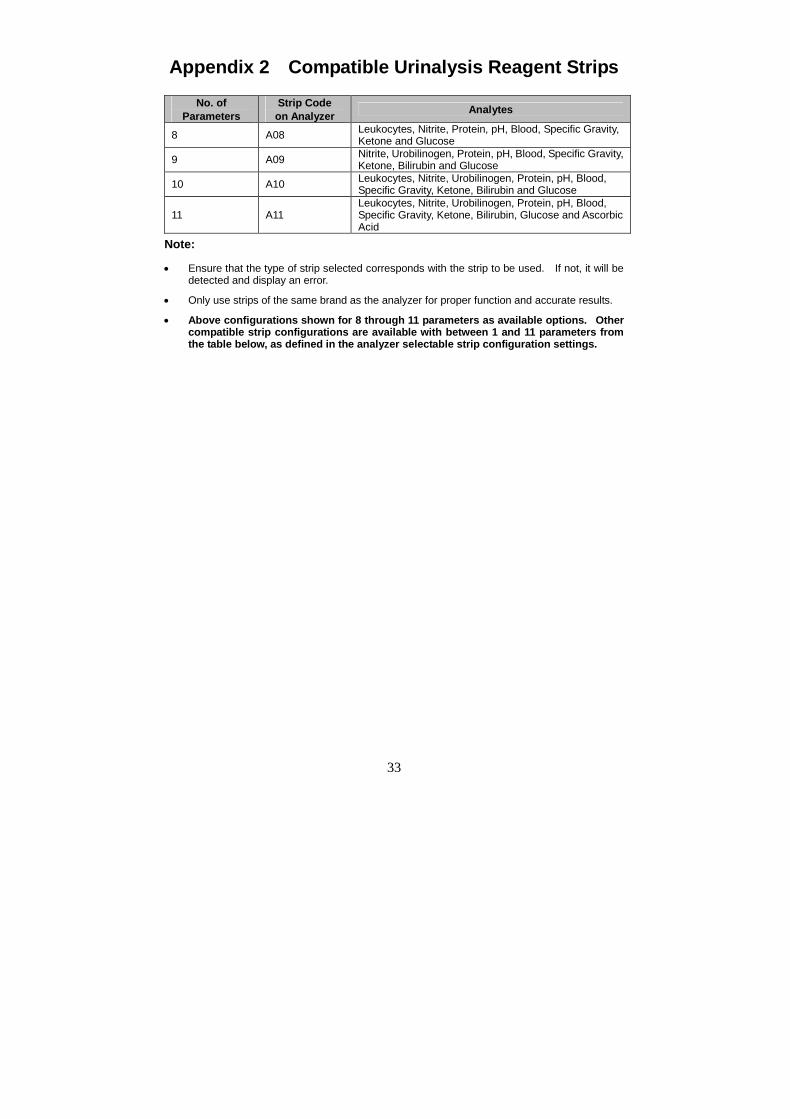
Appendix 2 Compatible Urinalysis Reagent Strips
No. ofParameters
Strip Codeon Analyzer Analytes
8 A08 Leukocytes, Nitrite, Protein, pH, Blood, Specific Gravity,Ketone and Glucose
9 A09 Nitrite, Urobilinogen, Protein, pH, Blood, Specific Gravity,Ketone, Bilirubin and Glucose
Ensure that the type of strip selected corresponds with the strip to be used. If not, it will bedetected and display an error.
Only use strips of the same brand as the analyzer for proper function and accurate results.
Above configurations shown for 8 through 11 parameters as available options. Othercompatible strip configurations are available with between 1 and 11 parameters fromthe table below, as defined in the analyzer selectable strip configuration settings.
34
Performance Characteristics of Urinalysis Reagent StripsThe performance characteristics of the Intermedical® Urinalysis Reagent Strips (Urine)have been determined in both laboratory and clinical tests. The following tableindicates performance characteristics for each parameter.
Detects ascorbic acid as lowas 5-10 mg/dL (0.28-0.56mmol/L).
Detects ascorbic acid as lowas 8-10 mg/dL (0.45-0.56mmol/L).
35
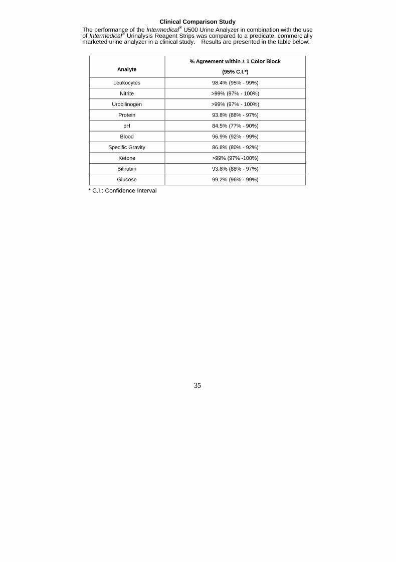
Clinical Comparison StudyThe performance of the Intermedical® U500 Urine Analyzer in combination with the useof Intermedical® Urinalysis Reagent Strips was compared to a predicate, commerciallymarketed urine analyzer in a clinical study. Results are presented in the table below:
* C.I.: Confidence Interval
Analyte% Agreement within ± 1 Color Block
(95% C.I.*)
Leukocytes 98.4% (95% - 99%)
Nitrite >99% (97% - 100%)
Urobilinogen >99% (97% - 100%)
Protein 93.8% (88% - 97%)
pH 84.5% (77% - 90%)
Blood 96.9% (92% - 99%)
Specific Gravity 86.8% (80% - 92%)
Ketone >99% (97% -100%)
Bilirubin 93.8% (88% - 97%)
Glucose 99.2% (96% - 99%)
36
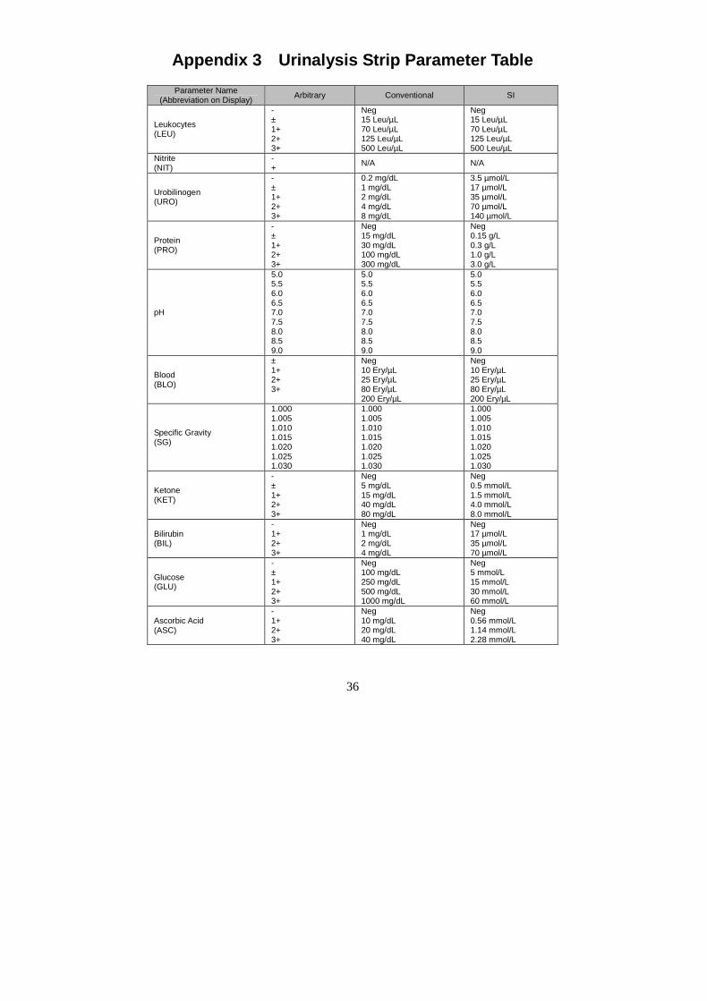
Appendix 3 Urinalysis Strip Parameter TableParameter Name
(Abbreviation on Display) Arbitrary Conventional SI
Leukocytes(LEU)
-±1+2+3+
Neg15 Leu/µL70 Leu/µL125 Leu/µL500 Leu/µL
Neg15 Leu/µL70 Leu/µL125 Leu/µL500 Leu/µL
Nitrite(NIT)
-+ N/A N/A
Urobilinogen(URO)
-±1+2+3+
0.2 mg/dL1 mg/dL2 mg/dL4 mg/dL8 mg/dL
3.5 µmol/L17 µmol/L35 µmol/L70 µmol/L140 µmol/L
Protein(PRO)
-±1+2+3+
Neg15 mg/dL30 mg/dL100 mg/dL300 mg/dL
Neg0.15 g/L0.3 g/L1.0 g/L3.0 g/L
pH
5.05.56.06.57.07.58.08.59.0
5.05.56.06.57.07.58.08.59.0
5.05.56.06.57.07.58.08.59.0
Blood(BLO)
±1+2+3+
Neg10 Ery/µL25 Ery/µL80 Ery/µL200 Ery/µL
Neg10 Ery/µL25 Ery/µL80 Ery/µL200 Ery/µL
Specific Gravity(SG)
1.0001.0051.0101.0151.0201.0251.030
1.0001.0051.0101.0151.0201.0251.030
1.0001.0051.0101.0151.0201.0251.030
Ketone(KET)
-±1+2+3+
Neg5 mg/dL15 mg/dL40 mg/dL80 mg/dL
Neg0.5 mmol/L1.5 mmol/L4.0 mmol/L8.0 mmol/L
Bilirubin(BIL)
-1+2+3+
Neg1 mg/dL2 mg/dL4 mg/dL
Neg17 µmol/L35 µmol/L70 µmol/L
Glucose(GLU)
-±1+2+3+
Neg100 mg/dL250 mg/dL500 mg/dL1000 mg/dL
Neg5 mmol/L15 mmol/L30 mmol/L60 mmol/L
Ascorbic Acid(ASC)
-1+2+3+
Neg10 mg/dL20 mg/dL40 mg/dL
Neg0.56 mmol/L1.14 mmol/L2.28 mmol/L
37
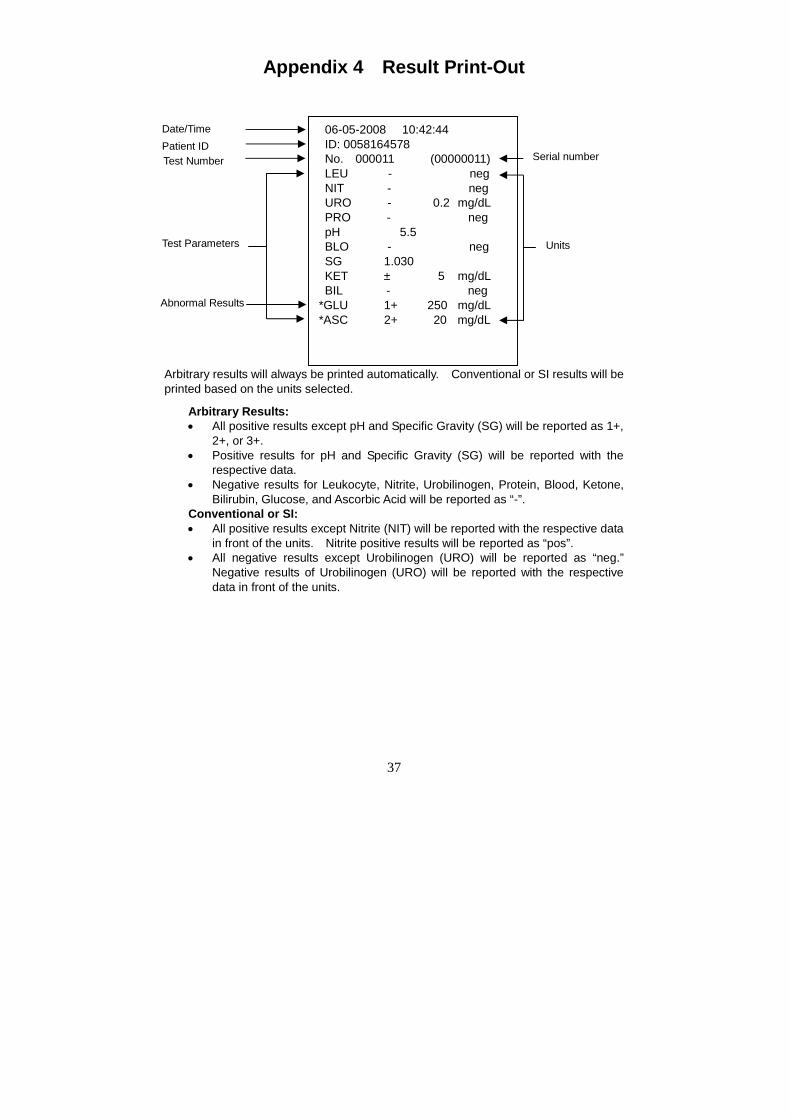
Appendix 4 Result Print-Out
Arbitrary results will always be printed automatically. Conventional or SI results will beprinted based on the units selected.
Arbitrary Results: All positive results except pH and Specific Gravity (SG) will be reported as 1+,
2+, or 3+. Positive results for pH and Specific Gravity (SG) will be reported with the
Bilirubin, Glucose, and Ascorbic Acid will be reported as “-”.Conventional or SI: All positive results except Nitrite (NIT) will be reported with the respective data
in front of the units. Nitrite positive results will be reported as “pos”. All negative results except Urobilinogen (URO) will be reported as “neg.”
Negative results of Urobilinogen (URO) will be reported with the respectivedata in front of the units.
06-05-2008 10:42:44 ID: 0058164578 No. 000011 (00000011) LEU - neg NIT - neg URO - 0.2 mg/dL PRO - neg pH 5.5 BLO - neg SG 1.030 KET ± 5 mg/dL BIL - neg*GLU 1+ 250 mg/dL*ASC 2+ 20 mg/dL
Date/Time
Test NumberPatient ID
Test Parameters
Abnormal Results
Units
Serial number
38
Appendix 5 Barcode Reader
The Intermedical® U500 Barcode Reader is an optional laser barcode scanner. TheBarcode Reader connects to the analyzer to scan the patient (ID) barcode numbers onthe specimen containers. The Barcode reader can scan the following:
Code 39 (Standard/ Full ASCII) Codabar (NW-7) Code 128
Italy Pharmacode UPCA EAN 128
French Pharmacode UPCE MSI
Industrial 25 EAN8 Plessey
Interleave 25 EAN13 Telepen
Matrix 25 Code 93 RSS
Note: Up to 25 digits can be read for each barcode.
39
Appendix 6 Catalog
Product Name CatalogNumber Components Quantity
U500 Urine Analyzer 1Strip Platform/Waste Tray 1Printer Paper Rolls 2Fuses (2.0 A) 2Power Cord 1
Instruction Manual 1Barcode Reader (RS232C) 1Serial Splitter Cable (RS232C) 1Barcode Reader U221-111Package Insert 1Thermal Paper (0.06 m x 20 m):200 results/roll 4
Printer Paper Rolls U121-101Sticker Paper (0.06 m x 9 m):100 results/roll; Optional 4
Data Transfer Cable(RS232C) 1
U500 Data Transfer Kit U221-131Package Insert 1
40
Appendix 7 Index of Symbols
Attention, seeinstructions foruse
Manufacturer AuthorizedRepresentative
For In vitrodiagnostic useonly
Lot Number REF Catalog #
Store between0-40°C
Tests per kit SN Serial number
Keep away fromsunlight and heat Use by Serial port
Keep dry Fragile, handlewith care This side up
Fuse type25 Pin ParallelExternal PrinterPort
Power Socket
Grounding Biohazard
41
Appendix 8 Warranty
Please complete the warranty card included in the packaging. Mail it to your localdistributor to register your purchase within one year of purchase.
For your records, write the purchase date of your starter kit here.
Note: This warranty applies only to the analyzer in the original purchase,and does not apply to the other materials included with theanalyzer.
INTERMEDICAL Laboratories, Inc. warrants to the original purchaser that this analyzerwill be free from defects in materials and workmanship for a period of one year (12months). The one year starts from the later of the date of original purchase orinstallation (except as noted below). During the stated one year period,INTERMEDICAL shall replace the unit under warranty with a reconditioned unit or, at itsoption, repair at no charge a unit that is found to be defective. INTERMEDICAL shallnot be responsible for shipping charges incurred in the repair of such an analyzer.
This warranty is subject to the following exceptions and limitations:
This warranty is limited to repair or replacement due to defects in parts or workmanship.Parts required which were not defective shall be replaced at additional cost, andINTERMEDICAL shall not be required to make any repairs or replace any parts that arenecessitated by abuse, accidents, alteration, misuse, neglect, failure to operate theanalyzer in accordance with the operations manual, or maintenance by anyone otherthan INTERMEDICAL. Furthermore, INTERMEDICAL assumes no liability frommalfunction or damage to analyzers caused by the use of strips other than stripsmanufactured by INTERMEDICAL. INTERMEDICAL reserves the right to makechanges in the design of this analyzer without obligation to incorporate such changesinto previously manufactured analyzers.
Disclaimer of Warranties
This warranty is expressly made in lieu of any and all other warranties express orimplied (either in fact or by operation of law) including the warranties of merchantabilityand fitness for use, which are expressly excluded, and is the only warranty given byINTERMEDICAL.
Limitations of Liability
In no event shall INTERMEDICAL be liable for indirect, special or consequentialdamages, even if INTERMEDICAL has been advised of the possibility of suchdamages.
For warranty service, please contact your local distributor.
42
Intermedical® U500 Urine Analyzer Warranty Card
Please complete this warranty card and mail it to your local distributor to register yourpurchase within 30 days of purchase. Refer to Appendix 8 Warranty in theInstruction Manual for details and terms of the product warranty.
Date ofPurchase
Purchaser Analyzer Serial Number (e.g. SN0000000. See label on back of analyzer)