Page 1
1
UART Program Examples
1. IntroductionThis Application Note provides to customers C and Assembler program examples forUART.
These examples are developped for the different configuration modes of this feature.
1.1 References• Atmel 8051 Microcontrollers Hardware Manual
8051 Microcontrollers
Application Note
Rev. 4346A–8051–06/04
Page 2
24346A–8051–06/04
2. C Example
2.1 Mode 1 (8 bit) with Timer1
/**
* @file $RCSfile: uart_t1.c,v $
* Copyright (c) 2004 Atmel.
* Please read file license.txt for copyright notice.
* @brief This file is an example to use uart with timer1.
* UART will echo a received data.
* This file can be parsed by Doxygen for automatic documentation
* generation.
* Put here the functional description of this file within the software
* architecture of your program.
* @version $Revision: 1.0 $ $Name: $
*/
/* @section I N C L U D E S */
#include "reg_c51.h"
char uart_data;
/**
* FUNCTION_PURPOSE: This file set up uart in mode 1 (8 bits uart) with
* timer 1 in mode 2 (8 bits auto reload timer).
* FUNCTION_INPUTS: void
* FUNCTION_OUTPUTS: void
*/
void main (void)
{
SCON = 0x50; /* uart in mode 1 (8 bit), REN=1 */
TMOD = TMOD | 0x20 ; /* Timer 1 in mode 2 */
TH1 = 0xFD; /* 9600 Bds at 11.059MHz */
TL1 = 0xFD; /* 9600 Bds at 11.059MHz */
ES = 1; /* Enable serial interrupt*/
EA = 1; /* Enable global interrupt */
TR1 = 1; /* Timer 1 run */
while(1); /* endless */
}
/**
* FUNCTION_PURPOSE: serial interrupt, echo received data.
* FUNCTION_INPUTS: P3.0(RXD) serial input
* FUNCTION_OUTPUTS: P3.1(TXD) serial output
*/
void serial_IT(void) interrupt 4
{
if (RI == 1)
{ /* if reception occur */
RI = 0; /* clear reception flag for next reception */
uart_data = SBUF; /* Read receive data */
SBUF = uart_data; /* Send back same data on uart*/
}
else TI = 0; /* if emission occur */
} /* clear emission flag for next emission*/
Page 3
34346A–8051–06/04
2.2 Mode 1 (8 bit) with Timer2
/**
* @file $RCSfile: uart_t2.c,v $
* Copyright (c) 2004 Atmel.
* Please read file license.txt for copyright notice.
* @brief This file is an example to use uart with timer2.
* UART will echo a received data.
* This file can be parsed by Doxygen for automatic documentation
* generation.
* Put here the functional description of this file within the software
* architecture of your program.
* @version $Revision: 1.0 $ $Name: $
*/
/* @section I N C L U D E S */
#include "reg_c51.h"
char uart_data;
/**
* FUNCTION_PURPOSE: This file set up uart in mode 1 (8 bits uart) with
* timer 2 in baud rate generator mode.
* FUNCTION_INPUTS: void
* FUNCTION_OUTPUTS: void
*/
void main (void)
{
SCON = 0x50; /* uart in mode 1 (8 bit), REN=1 */
T2CON &= 0xF0; /* EXEN2=0; TR2=0; C/T2#=0; CP/RL2#=0; */
T2CON |= 0x30; /* RCLK = 1; TCLK=1; */
TH2=0xFF; /* init value */
TL2=0xFD; /* init value */
RCAP2H=0xFF; /* reload value, 115200 Bds at 11.059MHz */
RCAP2L=0xFD; /* reload value, 115200 Bds at 11.059MHz */
ES = 1; /* Enable serial interrupt */
EA = 1; /* Enable global interrupt */
TR2 = 1; /* Timer 2 run */
while(1); /* endless */
}
/**
* FUNCTION_PURPOSE: serial interrupt, echo received data.
* FUNCTION_INPUTS: P3.0(RXD) serial input
* FUNCTION_OUTPUTS: P3.1(TXD) serial output
*/
void serial_IT(void) interrupt 4
{
if (RI == 1)
{ /* if reception occur */
RI = 0; /* clear reception flag for next reception */
uart_data = SBUF; /* Read receive data */
SBUF = uart_data; /* Send back same data on uart*/
}
else TI = 0; /* if emission occur */
} /* clear emission flag for next emission*/
Page 4
44346A–8051–06/04
2.3 Mode 1 (8 bit) with internal baud rate generator
/**
* @file $RCSfile: uart_int_brg.c,v $
* Copyright (c) 2004 Atmel.
* Please read file license.txt for copyright notice.
* @brief This file is an example to use uart with internal baud rate * generator.
* UART will echo a received data.
* This file can be parsed by Doxygen for automatic documentation
* generation.
* Put here the functional description of this file within the software
* architecture of your program.
* @version $Revision: 1.0 $ $Name: $
*/
/* @section I N C L U D E S */
#include "reg_c51.h"
char uart_data;
/**
* FUNCTION_PURPOSE: This file set up uart in mode 1 (8 bits uart) with
* internal baud rate generator.
* FUNCTION_INPUTS: void
* FUNCTION_OUTPUTS: void
*/
void main (void)
{
CKCON0 = 0x7F;
SCON = 0x50; /* uart in mode 1 (8 bit), REN=1 */
BDRCON &=0xEE; /* BRR=0; SRC=0; */
BDRCON |=0x0E; /* TBCK=1;RBCK=1; SPD=1 */
BRL=0xFD; /* 9600 Bds at 11.059MHz */
ES = 1; /* Enable serial interrupt*/
EA = 1; /* Enable global interrupt */
BDRCON |=0x10; /* Baud rate generator run*/
while(1); /* endless */
}
/**
* FUNCTION_PURPOSE: serial interrupt, echo received data.
* FUNCTION_INPUTS: P3.0(RXD) serial input
* FUNCTION_OUTPUTS: P3.1(TXD) serial output
*/
void serial_IT(void) interrupt 4
{
if (RI == 1)
{ /* if reception occur */
RI = 0; /* clear reception flag for next reception */
uart_data = SBUF; /* Read receive data */
SBUF = uart_data; /* Send back same data on uart*/
}
else TI = 0; /* if emission occur */
/* clear emission flag for next emission*/
}
Page 5
54346A–8051–06/04
2.4 Mode 3 (8 bit) Multiprocessor communications
2.4.1 Master/**
* @file $RCSfile: uart_multiproc_master.c,v $
*
* Copyright (c) 2004 Atmel.
*
* Please read file license.txt for copyright notice.
*
* @brief This file is an example to use uart with timer in
* multiprocessor mode.
*
* This file can be parsed by Doxygen for automatic documentation
* generation.
* Put here the functional description of this file within the software
* architecture of your program.
*
* @version $Revision: 1.0 $ $Name: $
*/
/* @section I N C L U D E S */
#include "reg_c51.h"
char uart_data;
char exemple_send_data=0x55;
char TxOK=0;
/**
* FUNCTION_PURPOSE: This file set up uart in mode 3 (9 bits uart) with
* timer 1 in baud rate generator mode.
* FUNCTION_INPUTS: P3.2(INT0)
* FUNCTION_OUTPUTS: void
*/
void main (void)
{
SCON = 0xF0; /* uart in mode 3 (9 bit), REN=1 */
SADDR=0x01; /* local address */
SADEN=0xFF; /* address mask */
TMOD = TMOD | 0x20 ; /* Timer 1 in mode 2 */
TH1 = 0xFD; /* 9600 Bds at 11.059MHz */
TL1 = 0xFD; /* 9600 Bds at 11.059MHz */
ES = 1; /* Enable serial interrupt */
EA = 1; /* Enable global interrupt */
TR1 = 1; /* Timer 1 run */
while(1) /* endless */
{
while(P3_2); /* wait P3_2(INT0)=0 */
while(!P3_2); /* wait P3_2(INT0)=1 */
TB8 = 1; /* address mode */
TxOK=1; /* set software flag */
SBUF = 0x03; /* send slave adress */
Page 6
64346A–8051–06/04
while(TxOK); /* wait the stop bit transmition */
TB8 = 0; /* data mode */
TxOK=1; /* set software flag */
SBUF = exemple_send_data; /* send data */
while(TxOK); /* wait the stop bit transmition */
}
}
/**
* FUNCTION_PURPOSE: serial interrupt.
* FUNCTION_INPUTS: P3.0(RXD) serial input
* FUNCTION_OUTPUTS: none
*/
void serial_IT(void) interrupt 4
{
if (TI == 1)
{ /* if reception occur */
TI=0; /* clear transmition flag for next transmition */
TxOK=0; /* clear software transmition flag */
}
if (RI == 1)
{ /* if reception occur */
RI = 0; /* clear reception flag for next reception */
if(RB8) SM2=0; /* go into data mode */
else
{
uart_data = SBUF; /* Read receive data */
SM2=1; /* return into address mode after receive data */
}
}
}
2.4.2 Slave /**
* @file $RCSfile:uart_multiproc_slave.c,v $
*
* Copyright (c) 2004 Atmel.
*
* Please read file license.txt for copyright notice.
*
* @brief This file is an example to use uart with timer in
* multiprocessor mode.
* Slave will echo a received data to master.
* This file can be parsed by Doxygen for automatic documentation
* generation.
* Put here the functional description of this file within the software
* architecture of your program.
*
Page 7
74346A–8051–06/04
* @version $Revision: 1.0 $ $Name: $
*/
/* @section I N C L U D E S */
#include "reg_c51.h"
char uart_data;
bit TxOK=0;
bit echo=0;
/**
* FUNCTION_PURPOSE: This file set up uart in mode 3 (9 bits uart) with
* timer 1 in baud rate generator mode.
* FUNCTION_INPUTS: void
* FUNCTION_OUTPUTS: P3.1(TXD) serial output
*/
void main (void)
{
SCON = 0xF0; /* uart in mode 3 (9 bit), REN=1 */
SADDR=0x03; /* local address */
SADEN=0xFF; /* address mask */
TMOD = TMOD | 0x20 ; /* Timer 1 in mode 2 */
TH1 = 0xFD; /* 9600 Bds at 11.059MHz */
TL1 = 0xFD; /* 9600 Bds at 11.059MHz */
ES = 1; /* Enable serial interrupt */
EA = 1; /* Enable global interrupt */
TR1 = 1; /* Timer 1 run */
while(1) /* endless */
{
while(!echo); /* wait data to echo */
echo = 0; /* disable echo */
TB8 = 1; /* address mode */
TxOK=1; /* set software flag */
SBUF = 0x01; /* send master adress */
while(TxOK); /* wait the stop bit transmition */
TB8 = 0; /* data mode */
TxOK=1; /* set software flag */
SBUF = uart_data; /* send data */
while(TxOK); /* wait the stop bit transmition */
}
}
/**
* FUNCTION_PURPOSE: serial interrupt, receive data to master
* FUNCTION_INPUTS: P3.0(RXD) serial input
* FUNCTION_OUTPUTS: none
*/
Page 8
84346A–8051–06/04
void serial_IT(void) interrupt 4
{
if (TI == 1)
{ /* if reception occur */
TI=0; /* clear transmition flag for next transmition */
TxOK=0; /* clear software transmition flag */
}
if (RI == 1)
{ /* if reception occur */
RI = 0; /* clear reception flag for next reception */
if(RB8) SM2=0; /* go into data mode */
else
{
uart_data = SBUF; /* Read receive data */
SM2=1; /* return into address mode after receive data */
echo=1; /* enable echo */
}
}
}
2.5 SFR Register Definition/*H***************************************************************************
* NAME: reg_c51.h
*----------------------------------------------------------------------------
* PURPOSE: SFR Description file for 8051 products
* ON KEIL compiler
*****************************************************************************/
#define Sfr(x, y) sfr x = y
#define Sbit(x, y, z) sbit x = y^z
#define Sfr16(x,y) sfr16 x = y
/*----------------------------------------*/
/* Include file for 8051 SFR Definitions */
Page 9
94346A–8051–06/04
/*----------------------------------------*/
/* BYTE Register */
Sfr (P0 , 0x80);
Sbit (P0_7 , 0x80, 7);
Sbit (P0_6 , 0x80, 6);
Sbit (P0_5 , 0x80, 5);
Sbit (P0_4 , 0x80, 4);
Sbit (P0_3 , 0x80, 3);
Sbit (P0_2 , 0x80, 2);
Sbit (P0_1 , 0x80, 1);
Sbit (P0_0 , 0x80, 0);
Sfr (P1 , 0x90);
Sbit (P1_7 , 0x90, 7);
Sbit (P1_6 , 0x90, 6);
Sbit (P1_5 , 0x90, 5);
Sbit (P1_4 , 0x90, 4);
Sbit (P1_3 , 0x90, 3);
Sbit (P1_2 , 0x90, 2);
Sbit (P1_1 , 0x90, 1);
Sbit (P1_0 , 0x90, 0);
Sfr (P2 , 0xA0);
Sbit (P2_7 , 0xA0, 7);
Sbit (P2_6 , 0xA0, 6);
Sbit (P2_5 , 0xA0, 5);
Sbit (P2_4 , 0xA0, 4);
Sbit (P2_3 , 0xA0, 3);
Sbit (P2_2 , 0xA0, 2);
Sbit (P2_1 , 0xA0, 1);
Sbit (P2_0 , 0xA0, 0);
Sfr (P3 , 0xB0);
Sbit (P3_7 , 0xB0, 7);
Sbit (P3_6 , 0xB0, 6);
Sbit (P3_5 , 0xB0, 5);
Sbit (P3_4 , 0xB0, 4);
Sbit (P3_3 , 0xB0, 3);
Sbit (P3_2 , 0xB0, 2);
Sbit (P3_1 , 0xB0, 1);
Sbit (P3_0 , 0xB0, 0);
Sbit (RD , 0xB0, 7);
Page 10
104346A–8051–06/04
Sbit (WR , 0xB0, 6);
Sbit (T1 , 0xB0, 5);
Sbit (T0 , 0xB0, 4);
Sbit (INT1 , 0xB0, 3);
Sbit (INT0 , 0xB0, 2);
Sbit (TXD , 0xB0, 1);
Sbit (RXD , 0xB0, 0);
Sfr (P4 , 0xC0);
Sbit (P4_7 , 0xC0, 7);
Sbit (P4_6 , 0xC0, 6);
Sbit (P4_5 , 0xC0, 5);
Sbit (P4_4 , 0xC0, 4);
Sbit (P4_3 , 0xC0, 3);
Sbit (P4_2 , 0xC0, 2);
Sbit (P4_1 , 0xC0, 1);
Sbit (P4_0 , 0xC0, 0);
Sfr (P5 , 0xE8);
Sbit (P5_7 , 0xE8, 7);
Sbit (P5_6 , 0xE8, 6);
Sbit (P5_5 , 0xE8, 5);
Sbit (P5_4 , 0xE8, 4);
Sbit (P5_3 , 0xE8, 3);
Sbit (P5_2 , 0xE8, 2);
Sbit (P5_1 , 0xE8, 1);
Sbit (P5_0 , 0xE8, 0);
Sfr (PSW , 0xD0);
Sbit (CY , 0xD0 , 7);
Sbit (AC , 0xD0 , 6);
Sbit (F0 , 0xD0 , 5);
Sbit (RS1 , 0xD0 , 4);
Sbit (RS0 , 0xD0 , 3);
Sbit (OV , 0xD0 , 2);
Sbit (UD , 0xD0 , 1);
Sbit (P , 0xD0 , 0);
Sfr (ACC , 0xE0);
Sfr (B , 0xF0);
Sfr (SP , 0x81);
Sfr (DPL , 0x82);
Sfr (DPH , 0x83);
Sfr (PCON , 0x87);
Sfr (CKCON0 , 0x8F);
Sfr (CKCON1 , 0xAF);
Page 11
114346A–8051–06/04
/*------------------ TIMERS registers ---------------------*/
Sfr (TCON , 0x88);
Sbit (TF1 , 0x88, 7);
Sbit (TR1 , 0x88, 6);
Sbit (TF0 , 0x88, 5);
Sbit (TR0 , 0x88, 4);
Sbit (IE1 , 0x88, 3);
Sbit (IT1 , 0x88, 2);
Sbit (IE0 , 0x88, 1);
Sbit (IT0 , 0x88, 0);
Sfr (TMOD , 0x89);
Sfr (T2CON , 0xC8);
Sbit (TF2 , 0xC8, 7);
Sbit (EXF2 , 0xC8, 6);
Sbit (RCLK , 0xC8, 5);
Sbit (TCLK , 0xC8, 4);
Sbit (EXEN2 , 0xC8, 3);
Sbit (TR2 , 0xC8, 2);
Sbit (C_T2 , 0xC8, 1);
Sbit (CP_RL2, 0xC8, 0);
Sfr (T2MOD , 0xC9);
Sfr (TL0 , 0x8A);
Sfr (TL1 , 0x8B);
Sfr (TL2 , 0xCC);
Sfr (TH0 , 0x8C);
Sfr (TH1 , 0x8D);
Sfr (TH2 , 0xCD);
Sfr (RCAP2L , 0xCA);
Sfr (RCAP2H , 0xCB);
Sfr (WDTRST , 0xA6);
Sfr (WDTPRG , 0xA7);
/*------------------- UART registers ------------------------*/
Sfr (SCON , 0x98);
Sbit (SM0 , 0x98, 7);
Sbit (FE , 0x98, 7);
Sbit (SM1 , 0x98, 6);
Sbit (SM2 , 0x98, 5);
Sbit (REN , 0x98, 4);
Sbit (TB8 , 0x98, 3);
Sbit (RB8 , 0x98, 2);
Sbit (TI , 0x98, 1);
Sbit (RI , 0x98, 0);
Sfr (SBUF , 0x99);
Sfr (SADEN , 0xB9);
Page 12
124346A–8051–06/04
Sfr (SADDR , 0xA9);
/*-------------------- Internal Baud Rate Generator --------*/
Sfr (BRL , 0x9A);
Sfr (BDRCON , 0x9B);
/*-------------------- IT registers -----------------------*/
Sfr (IEN0 , 0xA8);
Sfr (IEN1 , 0xB1);
Sfr (IPH0 , 0xB7);
Sfr (IPH1 , 0xB3);
Sfr (IPL0 , 0xB8);
Sfr (IPL1 , 0xB2);
/* IEN0 */
Sbit (EA , 0xA8, 7);
Sbit (EC , 0xA8, 6);
Sbit (ET2 , 0xA8, 5);
Sbit (ES , 0xA8, 4);
Sbit (ET1 , 0xA8, 3);
Sbit (EX1 , 0xA8, 2);
Sbit (ET0 , 0xA8, 1);
Sbit (EX0 , 0xA8, 0);
/*--------------------- PCA registers -----------------------------*/
Sfr (CCON , 0xD8);
Sfr (CMOD , 0xD9);
Sfr (CH , 0xF9);
Sfr (CL , 0xE9);
Sfr (CCAP0H , 0xFA);
Sfr (CCAP0L , 0xEA);
Sfr (CCAPM0 , 0xDA);
Sfr (CCAP1H , 0xFB);
Sfr (CCAP1L , 0xEB);
Sfr (CCAPM1 , 0xDB);
Sfr (CCAP2H , 0xFC);
Sfr (CCAP2L , 0xEC);
Sfr (CCAPM2 , 0xDC);
Sfr (CCAP3H , 0xFD);
Sfr (CCAP3L , 0xED);
Sfr (CCAPM3 , 0xDD);
Sfr (CCAP4H , 0xFE);
Sfr (CCAP4L , 0xEE);
Sfr (CCAPM4 , 0xDE);
/* CCON */
Page 13
134346A–8051–06/04
Sbit (CF , 0xD8, 7);
Sbit (CR , 0xD8, 6);
Sbit (CCF4 , 0xD8, 4);
Sbit (CCF3 , 0xD8, 3);
Sbit (CCF2 , 0xD8, 2);
Sbit (CCF1 , 0xD8, 1);
Sbit (CCF0 , 0xD8, 0);
/*------------------ T W I registers ------------------------------*/
Sfr ( SSCON , 0x93);
Sfr ( SSCS , 0x94);
Sfr ( SSDAT , 0x95);
Sfr ( SSADR , 0x96);
Sfr ( PI2, 0xF8);
Sbit (PI2_1 , 0xF8, 1);
Sbit (PI2_0 , 0xF8, 0);
/*-------------------- OSC control registers ----------------------*/
Sfr ( CKSEL , 0x85 );
Sfr ( OSCCON , 0x86 );
Sfr ( CKRL , 0x97 );
/*-------------------- Keyboard control registers -----------------*/
Sfr ( KBLS , 0x9C );
Sfr ( KBE , 0x9D );
Sfr ( KBF , 0x9E );
/*-------------------- SPI ---------------------- -----------------*/
Sfr ( SPCON, 0xC3 );
Sfr ( SPSTA, 0xC4 );
Sfr ( SPDAT, 0xC5 );
/*------ Misc ----------------------------------------------------*/
Sfr( AUXR , 0x8E);
Sfr ( AUXR1, 0xA2);
Sfr ( FCON, 0xD1);
/*------ E data --------------------------------------------------*/
Sfr ( EECON, 0xD2 );
Page 14
144346A–8051–06/04
3. Assembler 51 Examples
3.1 UARTMode 1 (8 bit) with Timer1
$INCLUDE (reg_c51.INC)
org 000h
ljmp begin
org 23h
ljmp serial_IT
;/**
; * FUNCTION_PURPOSE: This file set up uart in mode 1 (8 bits uart) with
; * timer 1 in mode 2 (8 bits auto reload timer).
; * FUNCTION_INPUTS: void
; * FUNCTION_OUTPUTS: void
; */
org 0100h
begin:
MOV SCON, #50h; /* uart in mode 1 (8 bit), REN=1 */
ORL TMOD, #20h; /* Timer 1 in mode 2 */
MOV TH1, #0FDh; /* 9600 Bds at 11.059MHz */
MOV TL1, #0FDh; /* 9600 Bds at 11.059MHz */
SETB ES; /* Enable serial interrupt*/
SETB EA; /* Enable global interrupt */
SETB TR1; /* Timer 1 run */
JMP $; /* endless */
;/**
; * FUNCTION_PURPOSE: serial interrupt, echo received data.
; * FUNCTION_INPUTS: P3.0(RXD) serial input
; * FUNCTION_OUTPUTS: P3.1(TXD) serial output
; */
serial_IT:
JNB RI,EMIT_IT ; test if it is a reception
CLR RI ; clear reception flag for next reception
MOV A,SBUF ; read data from uart
MOV SBUF,A ; write same data to uart
LJMP END_IT
EMIT_IT:
CLR TI ; clear transmition flag for next transmition
END_IT:
RETI
end
Page 15
154346A–8051–06/04
3.2 Mode 1 (8 bit) with Timer2$INCLUDE (reg_c51.INC)
org 000h
ljmp begin
org 23h
ljmp serial_IT
;/**
; * FUNCTION_PURPOSE: This file set up uart in mode 1 (8 bits uart) with
; * timer 2 in baud rate generator mode.
; * FUNCTION_INPUTS: void
; * FUNCTION_OUTPUTS: void
; */
org 0100h
begin:
MOV SCON,#50h; /* uart in mode 1 (8 bit), REN=1 */
ANL T2CON,#0F0h; /* EXEN2=0; TR2=0; C/T2#=0; CP/RL2#=0; */
ORL T2CON,#30h; /* RCLK = 1; TCLK=1; */
MOV TH2,#0FFh; /* init value */
MOV TL2,#0FDh; /* init value */
MOV RCAP2H,#0FFh; /* reload value, 115200 Bds at 11.059MHz */
MOV RCAP2L,#0FDh; /* reload value, 115200 Bds at 11.059MHz */
SETB ES; /* Enable serial interrupt */
SETB EA; /* Enable global interrupt */
SETB TR2; /* Timer 2 run */
JMP $; /* endless */
;/**
; * FUNCTION_PURPOSE: serial interrupt, echo received data.
; * FUNCTION_INPUTS: P3.0(RXD) serial input
; * FUNCTION_OUTPUTS: P3.1(TXD) serial output
; */
serial_IT:
JNB RI,EMIT_IT ; test if it is a reception
CLR RI ; clear reception flag for next reception
MOV A,SBUF ; read data from uart
MOV SBUF,A ; write same data to uart
LJMP END_IT
EMIT_IT:
CLR TI ; clear transmition flag for next transmition
END_IT:
RETI
end
Page 16
164346A–8051–06/04
3.3 Mode 1 (8 bit) with internal baud rate generator$INCLUDE (reg_c51.INC)
org 000h
ljmp begin
org 23h
ljmp serial_IT
;/**
; * FUNCTION_PURPOSE: This file set up uart in mode 1 (8 bits uart) with
; * internal baud rate generator.
; * FUNCTION_INPUTS: void
; * FUNCTION_OUTPUTS: void
; */
org 0100h
begin:
MOV SCON,#50h; /* uart in mode 1 (8 bit), REN=1 */
ANL BDRCON,#0EEh; /* BRR=0; SRC=0; */
ORL BDRCON,#0Eh; /* TBCK=1;RBCK=1; SPD=1 */
MOV BRL,#0FDh; /* 9600 Bds at 11.059MHz */
SETB ES; /* Enable serial interrupt*/
SETB EA; /* Enable global interrupt */
ORL BDRCON,#10h; /* Baud rate generator run*/
JMP $; /* endless */
;/**
; * FUNCTION_PURPOSE: serial interrupt, echo received data.
; * FUNCTION_INPUTS: P3.0(RXD) serial input
; * FUNCTION_OUTPUTS: P3.1(TXD) serial output
; */
serial_IT:
JNB RI,EMIT_IT ; test if it is a reception
CLR RI ; clear reception flag for next reception
MOV A,SBUF ; read data from uart
MOV SBUF,A ; write same data to uart
LJMP END_IT
EMIT_IT:
CLR TI ; clear transmition flag for next transmition
END_IT:
RETI
end
Page 17
174346A–8051–06/04
3.4 Mode 3 (9 bit) Multiprocessor Communications
3.4.1 Master $INCLUDE (reg_c51.INC)
TxOK BIT 21H; software flag
org 000h
ljmp begin
org 23h
ljmp serial_IT
;/**
; * FUNCTION_PURPOSE: This file set up uart in mode 3 (9 bits uart) with
; * timer 1 in baud rate generator mode.
; * FUNCTION_INPUTS: P3.2(INT0)
; * FUNCTION_OUTPUTS: void
; */
org 0100h
begin:
MOV SCON, #0F0h; /* uart in mode 3 (9 bit), REN=1 */
MOV SADDR,#01h; /* local address */
MOV SADEN,#0FFh; /* address mask */
ORL TMOD, #20h; /* Timer 1 in mode 2 */
MOV TH1, #0FDh; /* 9600 Bds at 11.059MHz */
MOV TL1, #0FDh; /* 9600 Bds at 11.059MHz */
SETB ES; /* Enable serial interrupt*/
SETB EA; /* Enable global interrupt */
SETB TR1; /* Timer 1 run */
loop:
JB P3.2,$; /* wait P3_2(INT0)=0 */
JNB P3.2,$; /* wait P3_2(INT0)=1 */
SETB TB8; /* address mode */
SETB TxOK; /* set software flag */
MOV SBUF,#03h; /* send slave adress */
JB TxOK,$; /* wait the stop bit transmition */
CLR TB8; /* data mode */
SETB TxOK; /* set software flag */
MOV SBUF,#55h; /* send data example */
JB TxOK,$; /* wait the stop bit transmition */
SJMP loop
;/**
; * FUNCTION_PURPOSE: serial interrupt,
; * FUNCTION_INPUTS: P3.0(RXD) serial input
Page 18
184346A–8051–06/04
; * FUNCTION_OUTPUTS: none
; */
serial_IT:
JNB TI,END_Test_TI
CLR TI
CLR TxOK
END_Test_TI:
JNB RI,END_Test_RI; /* test if it is a reception */
CLR RI; /* clear reception flag for next reception */
JNB RB8,address_mode
CLR SM2; /* go into data mode */
LJMP END_Test_RB8
address_mode:
MOV A,SBUF; /* Read receive data */
SETB SM2; /* return into address mode after receive data */
MOV P2,A
END_Test_RB8:
END_Test_RI:
RETI
end
3.4.2 Slave $INCLUDE (reg_c51.INC)
echo BIT 20H; echo enable bit
TxOK BIT 21H; software flag
org 000h
ljmp begin
org 23h
ljmp serial_IT
/**
* FUNCTION_PURPOSE: This file set up uart in mode 3 (9 bits uart) with
* timer 1 in baud rate generator mode.
* FUNCTION_INPUTS: void
* FUNCTION_OUTPUTS: void
*/
org 0100h
begin:
MOV SCON, #0F0h; /* uart in mode 3 (9 bit), REN=1 */
MOV SADDR,#03h; /* local address */
MOV SADEN,#0FFh; /* address mask */
ORL TMOD, #20h; /* Timer 1 in mode 2 */
MOV TH1, #0FDh; /* 9600 Bds at 11.059MHz */
MOV TL1, #0FDh; /* 9600 Bds at 11.059MHz */
SETB ES; /* Enable serial interrupt*/
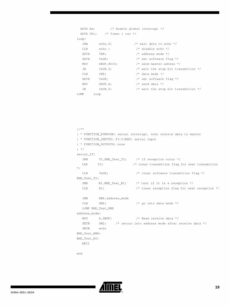
Page 19
194346A–8051–06/04
SETB EA; /* Enable global interrupt */
SETB TR1; /* Timer 1 run */
loop:
JNB echo,$; /* wait data to echo */
CLR echo ; /* disable echo */
SETB TB8; /* address mode */
SETB TxOK; /* set software flag */
MOV SBUF,#01h; /* send master adress */
JB TxOK,$; /* wait the stop bit transmition */
CLR TB8; /* data mode */
SETB TxOK; /* set software flag */
MOV SBUF,A; /* send data */
JB TxOK,$; /* wait the stop bit transmition */
LJMP loop
;/**
; * FUNCTION_PURPOSE: serial interrupt, echo receive data to master
; * FUNCTION_INPUTS: P3.0(RXD) serial input
; * FUNCTION_OUTPUTS: none
; */
serial_IT:
JNB TI,END_Test_TI; /* if reception occur */
CLR TI; /* clear transmition flag for next transmition */
CLR TxOK; /* clear software transmition flag */
END_Test_TI:
JNB RI,END_Test_RI; /* test if it is a reception */
CLR RI; /* clear reception flag for next reception */
JNB RB8,address_mode
CLR SM2; /* go into data mode */
LJMP END_Test_RB8
address_mode:
MOV A,SBUF; /* Read receive data */
SETB SM2; /* return into address mode after receive data */
SETB echo
END_Test_RB8:
END_Test_RI:
RETI
end
Page 20
204346A–8051–06/04
3.5 SFR Register Definition
$SAVE
$NOLIST
P0 DATA 80H
TCONDATA88H
;--- TCON Bits ---
TF1 BIT 8FH
TR1 BIT 8EH
TF0 BIT 8DH
TR0 BIT 8CH
IE1 BIT 8BH
IT1 BIT 8AH
IE0 BIT 89H
IT0 BIT 88H
P1 DATA 90H
SCON DATA 98H
;--- SCON Bits ----
SM0 BIT 9FH
SM1 BIT 9EH
SM2 BIT 9DH
REN BIT 9CH
TB8 BIT 9BH
RB8 BIT 9AH
TI BIT 99H
RI BIT 98H
P2 DATA 0A0H
IEN0 DATA 0A8H
;--- IEN0 Bits -----
EA BIT0AFH
EC BIT0AEH
ET2 BIT0ADH
ES BIT0ACH
ET1 BIT0ABH
EX1 BIT0AAH
ET0 BIT0A9H
EX0BIT0A8H
P3 DATA 0B0H
;--- P3 Bits -------
RD BIT 0B7H
WR BIT 0B6H
T1 BIT 0B5H
T0 BIT 0B4H
INT1 BIT 0B3H
INT0 BIT 0B2H
Page 21
214346A–8051–06/04
TXD BIT 0B1H
RXD BIT 0B0H
P4 DATA 0C0H
P5 DATA 0E8H
IPL0DATA0B8H
;--- IPL0 Bits -----
PPCL BIT0BEH
PT2L BIT0BDH
PSL BIT0BCH
PT1L BIT0BBH
PX1L BIT0BAH
PT0L BIT0B9H
PX0LBIT0B8H
T2CON DATA 0C8H
;--- T2CON bits ----
TF2 BIT 0CFH
EXF2 BIT 0CEH
RCLK BIT 0CDH
TCLK BIT 0CCH
EXEN2 BIT 0CBH
TR2 BIT 0CAH
C_T2 BIT 0C9H
CP_RL2 BIT 0C8H
PSW DATA 0D0H
;--- PSW bits ------
CY BIT 0D7H
AC BIT 0D6H
F0 BIT 0D5H
RS1 BIT 0D4H
RS0 BIT 0D3H
OV BIT 0D2H
P BIT 0D0H
CCONDATA0D8H
;--- CCON bits -----
CF BIT 0DFH
CR BIT 0DEH
CCF4 BIT 0DCH
CCF3 BIT 0DBH
CCF2 BIT 0DAH
CCF1 BIT 0D9H
CCF0 BIT 0D8H
ACC DATA 0E0H
Page 22
224346A–8051–06/04
B DATA 0F0H
SP DATA 81H
DPL DATA 82H
DPH DATA 83H
PCON DATA 87H
TMOD DATA 89H
TL0 DATA 8AH
TL1 DATA 8BH
TH0 DATA 8CH
TH1 DATA 8DH
AUXRDATA08EH
CKCON0DATA08Fh
SBUF DATA 99H
;-- Baud Rate generator
BRL DATA09AH
BDRCON DATA 09BH
;--- Keyboard
KBLSDATA09CH
KBEDATA09DH
KBFDATA09EH
;--- Watchdog timer
WDTRSTDATA0A6H
WDTPRG DATA0A7H
SADDRDATA0A9H
CKCON1DATA0AFH
IEN1DATA0B1H
IPL1DATA0B2H
IPH1DATA0B3H
IPH0DATA0B7H
SADENDATA0B9H
T2MODDATA 0C9h
Page 23
234346A–8051–06/04
RCAP2L DATA 0CAH
RCAP2H DATA 0CBH
TL2 DATA 0CCH
TH2 DATA 0CDH
CMODDATA0D9H
CCAPM0DATA0DAH
CCAPM1DATA0DBH
CCAPM2DATA0DCH
CCAPM3DATA0DDH
CCAPM4DATA0DEH
CHDATA0F9H
CCAP0HDATA0FAH
CCAP1HDATA0FBH
CCAP2HDATA0FCH
CCAP3HDATA0FDH
CCAP4HDATA0FEH
CLDATA0E9H
CCAP0LDATA0EAH
CCAP1LDATA0EBH
CCAP2LDATA0ECH
CCAP3LDATA0EDH
CCAP4LDATA0EEH
; SPI
SPCON DATA 0C3H
SPSTA DATA 0C4H
SPDAT DATA 0C5H
; TWI
PI2DATA 0F8h
SSCONDATA093H
SSCSDATA094H
SSDATDATA095H
SSADRDATA096H
PI2_OBIT0F8H
PI2_1BIT0F9H
; Clock Control
OSCCONDATA086H
CKSELDATA085H
CKRLDATA097H
;MISC
AUXR1DATA0A2H
Page 24
244346A–8051–06/04
; Flash control
FCON DATA 0D1H
;EEData
EECONDATA0D2H
$RESTORE
Page 25
Table of Contents
1
Table of Contents
Introduction........................................................................................... 1References ........................................................................................................... 1
C Example.............................................................................................. 2Mode 1 (8 bit) with Timer1.................................................................................... 2Mode 1 (8 bit) with Timer2.................................................................................... 3Mode 1 (8 bit) with internal baud rate generator .................................................. 4Mode 3 (8 bit) Multiprocessor communications.................................................... 5
Master............................................................................................................. 5Slave ............................................................................................................... 6
SFR Register Definition........................................................................................ 8
Assembler 51 Examples..................................................................... 14UART
Mode 1 (8 bit) with Timer1 ........................................................................................... 14Mode 1 (8 bit) with Timer2.................................................................................. 15Mode 1 (8 bit) with internal baud rate generator ................................................ 16Mode 3 (9 bit) Multiprocessor Communications ................................................. 17
Master 17Slave 18
SFR Register Definition...................................................................................... 20
Page 26
Printed on recycled paper.
© Atmel Corporation 2004. All rights reserved. Atmel® and combinations thereof are the registered trademarks of Atmel Corporation or itssubsidiaries. Other terms and product names may be the trademarks of others.
Disclaimer: Atmel Corporation makes no warranty for the use of its products, other than those expressly contained in the Company’s standardwarranty which is detailed in Atmel’s Terms and Conditions located on the Company’s web site. The Company assumes no responsibility for anyerrors which may appear in this document, reserves the right to change devices or specifications detailed herein at any time without notice, anddoes not make any commitment to update the information contained herein. No licenses to patents or other intellectual property of Atmel aregranted by the Company in connection with the sale of Atmel products, expressly or by implication. Atmel’s products are not authorized for useas critical components in life support devices or systems.
Atmel Corporation Atmel Operations
2325 Orchard ParkwaySan Jose, CA 95131Tel: 1(408) 441-0311Fax: 1(408) 487-2600
Regional Headquarters
EuropeAtmel SarlRoute des Arsenaux 41Case Postale 80CH-1705 FribourgSwitzerlandTel: (41) 26-426-5555Fax: (41) 26-426-5500
AsiaRoom 1219Chinachem Golden Plaza77 Mody Road TsimshatsuiEast KowloonHong KongTel: (852) 2721-9778Fax: (852) 2722-1369
Japan9F, Tonetsu Shinkawa Bldg.1-24-8 ShinkawaChuo-ku, Tokyo 104-0033JapanTel: (81) 3-3523-3551Fax: (81) 3-3523-7581
Memory2325 Orchard ParkwaySan Jose, CA 95131Tel: 1(408) 441-0311Fax: 1(408) 436-4314
Microcontrollers2325 Orchard ParkwaySan Jose, CA 95131Tel: 1(408) 441-0311Fax: 1(408) 436-4314
La ChantrerieBP 7060244306 Nantes Cedex 3, FranceTel: (33) 2-40-18-18-18Fax: (33) 2-40-18-19-60
ASIC/ASSP/Smart CardsZone Industrielle13106 Rousset Cedex, FranceTel: (33) 4-42-53-60-00Fax: (33) 4-42-53-60-01
1150 East Cheyenne Mtn. Blvd.Colorado Springs, CO 80906Tel: 1(719) 576-3300Fax: 1(719) 540-1759
Scottish Enterprise Technology ParkMaxwell BuildingEast Kilbride G75 0QR, Scotland Tel: (44) 1355-803-000Fax: (44) 1355-242-743
RF/AutomotiveTheresienstrasse 2Postfach 353574025 Heilbronn, GermanyTel: (49) 71-31-67-0Fax: (49) 71-31-67-2340
1150 East Cheyenne Mtn. Blvd.Colorado Springs, CO 80906Tel: 1(719) 576-3300Fax: 1(719) 540-1759
Biometrics/Imaging/Hi-Rel MPU/High Speed Converters/RF Datacom
Avenue de RochepleineBP 12338521 Saint-Egreve Cedex, FranceTel: (33) 4-76-58-30-00Fax: (33) 4-76-58-34-80
[email protected]
Web Sitehttp://www.atmel.com
4346A–8051–06/04 /xM