UCRL-15133 CONCEPTUAL REPORT (SANL 707-101) HIGH-VOLTAGE POWER SUPPLY SYSTEM FOR LASER ISOTOPE SEPARATION E. C. Ketaily Energy Technology Engineering Center Energy Systems Group Rockwell International Canoga Park, California R. P. Buckner and R. L. Uhrik Collins Telecommunication Systems Division Electronics Systems Group Rockwell International Dallas, Texas June 26, 1979 L! LAWRENCE UVERMORE LABORATORY UMrWyriOabmk tarn o? TM mxw <% ^LIMITES
Transcript
UCRL-15133
CONCEPTUAL REPORT (SANL 707-101) HIGH-VOLTAGE POWER SUPPLY SYSTEM FOR LASER ISOTOPE SEPARATION E. C. Ketaily Energy Technology Engineering Center Energy Systems Group Rockwell International Canoga Park, California R. P. Buckner and R. L. Uhrik Collins Telecommunication Systems Division Electronics Systems Group Rockwell International Dallas, Texas
June 26, 1979
L! LAWRENCE UVERMORE LABORATORY UMrWyriOabmk
tarn o? TM mxw <% L̂IMITES
ilORL 1513 3
CONCEPTUAL REPORT
HIGH-VOLTAGE POWEH SUPPLY SYSTEM FOR
LASER ISOTOPE SEPARATION
June 26, 1979
by
E. C. Ketaily
Energy Tephnology Engineering .Center-Energy Systems Group
Rockwell International , Canoga Park, California
and V
R. P. Buckner and H, L. Uhrik / Collins Telecoimunioation Systems Division
Electronics Systems Group Rockwell International
Dallas, Texas
This dc.ument is a result of technical investigations lade by Rockwell International. Although this document hao been approved for limited release outside the company, the reader is hereby advised that this document contains proprietary data of Rockwell International.
rt«s-H!<sirri»-, £:- r,i.s PUCUMCHT IS UNUMiTa
PREFACE
This report presents several concepts for Laser High-Voltage Power Supply (HVPS) Systems for a Laser Isotope Separation facility. Selection of equipments and their arrangement into operational systems is based on proven designs and on application concepts now being developed. As such, the systems described utilize standard commercial practice. Special development of components and circuit technology are noc anticipated for these applications.
This report has not attempted to select an optimum design approach for the total system requirement, but has identified a number of alternative system arrangements and has provided preliminary cost estimates for each. The report includes a recommendation for follow-on studies that will further define the optimum Laser HVPS Systems.'
Detailed studies of Modulator/Regulator circuit tr-de-offs, system control interfaces, and their related impact on costs are not included in the report, but brief descriptions of these considerations are given.
i
TABLE OF CONTENTS
Preface . ,
1. SUMMARY •
2. THE REQUIREMENT 2.1 Application and Intended Use 2.2 Load Characteristics 2.3 Power Line Characteristics 2 J HVPS Specification.
3. CHARACTERISTICS OF THE HIGH-VOLUGE POKER SUPPLY,
3.1 The Baseline Design
3.2 Vacuum-Tube Modulator/Begulator ,
3-3 Transformer/Rectifier
3 . " Control Interface
3.5 HVPS Power Estimate
3.6 Baseline O - t Estimates .
1. LOAD SCENARIOS
•f.1 Introduction •
1.2 Scenario Definition , , , , .
J).3 Optimum Scenario .
5. SYSTEM OPTIMIZATION 5.1 Possible Variations 5.2 Load Scenario Considerations , 5.3 Laser HVPS System Cost Estimates
Laser HVPS System 2-1 HVPS Load Circuit 2-3 HVPS Block Diagram 3-2 HVPS Typical Packaging 3-3 Simplified Schematic, HVPS Modulator/Regulator Section. . . 3-5 Simplified Schematic, HVPS Transformer/Rectifier Section. . 3-7 HVPS Power Budget Estimates 3-9 Scenario A - Power Supply for 250 Laser Loads 1-3 Scenario B - Variable Voltage Power Supply for 250 Laser Loads - . . . 1-5
Scenario C - One High Voltage Power Supply per Laser Load . 1-6 Elements Required to Convert 13-8 kvac to 6.0 kvdc 5-2 How Total 25 MH is Br Ken Down for Scenarios A and B. . . . 5-1 Switohgear/Rectifier Transformer Assemblies -Typical Four Places 5-6
Induction Voltage Regulator . 6-2 Saturable Core Reactor 6-1 Tap Ch?nging Step Voltage Regulator 6-5 Silicon Controlled Rectifier 6-7
iii
1.0 SUMMARY
This report describes several configurations of laser high-voltage power supplies (HVPS's) suitable for use in a laser isotope separation facility. As many as 1000 to 1200 separate laser HVPS systems may be required in the total process facility, and the objective of this conceptual study is to identify how such a large amount of equipment might be economically arranged. The HVPS subsystems are characterized by estimating their cost, size, weight, performance, etc., and are evaluated in terms of how well they meet the system requirement.
The report begins by defining the power supplies as elements of individual laser HVPS systems, wherein performance can only be optimized by considering the influencing parameters of the power source and the laser load, as well as those of the HVPS itself. In fact, the load characteristics emerge a3 the key factors in determining power supply suitability for this application, and the report suggests future studies that may produce substantial reducions in system cost by changing and optimizing the laser thyratrcn charging circuits themselves. For this initial concept study, however, the laser loads were treated as simple r&sistors, and a preliminary specification (Table 2-1, page 2-5) was compiled based on this and other simplifying assumptions.
Since one system arrangement would have each of the 1000 laser loads powered by a separate HVPS (each rated at 25 kU), a "baseline" preliminary design is presented consisting of separately-packaged transformer/rectifier and modulator/regulator sections, requiring cabinets of 3 by 3 by 3 ft and 2 by 3 by 3 ft, respectively, and which together make up an individual 25-kW HVPS. Each baseline HVPS is estimated to cost $18,700 and would operate with an overall efficiency of 6*\i. The relatively low efficiency is primarily dua to the use of a series vacuum-tube modulator/regulator, and the report discusses how system cost could be reduced and operating efficiency increased if the series tube could be eliminated.
1-1
The concept study has assumed that an individual series f-ube modulator/ regulator is rtquired for each laser load, but it is clearly possible to operate several series tubes from a common DC distribution bus, with significant cost reductions. For this reason, the study has examined several "Load Scenarios," wherein common transformer/rectifier arrangements are characterized. The report defines only the limit cases of these arrangements - those driving as many as 250 loads from a common bus, and those having a separate supply for each loacf - but suggests that an optimum scenario lying between these extremes would probably be preferred. The study has not attempted to choose an optimum, however, because such "fine tuning" of the baseline concept is overshadowed by the possibility of substantial changes in the system arrangement that might totally eliminate the series tube modulator/regulators.
The report defines these potential changes as "other options," and describes how the use of pre-regulation instead of a fixed-voltage transformer/ rectifier might be combined with simple protective switching to eliminate the .series tubes for greatly reduced system cost and increased system reliability. Such changes are entirely dependent on the possibility of modifying the laser head resonant charging and thyratron firing circuits, however, and the report suggests that a reconsideration of these circuits - with possible laboratory tests - might be a logical next step.
The report concludes by recommending future areas of study that would further define the laser HVPS's and permit a best optimization of the future system. At least four steps of the recommended future work seem especially attractive:
1) Definition of the load requirement, with emphasis on innovations in the laser charging and firing circuits.
2) Development of guidelines for system optimization.
3) Detailed development of load scenarios.
!|) Selection of an optimum design.
1-2
2.0 THE REQUIREMENT
2.1 Application and Intended Use
The specification of Laser High-Voltage Power Supplies (HVPS) for Laser Isotope Separation must begin with a consideration of the intended application of the resulting system. Because of the sensitivity of the isotope separation process in general, this report has included only a brief description of the lasers and their functions.
Figure 2-1 illustrates and defines a typical Laser HVPS System as an HV power supply operating from commercial power and supplying DC power to an individual copper-vapor laser head, which in turn imparts energy to the isotope separation process. The laser heads are grouped in chains of 5 to 8 lasers and the chains are in turn grouped into modules containing .100 tc 200 lasers. Sufficient redundancy will exist so that the isotope separation process can continue with one module (100 to 200 lasers and HVPS's) removed from service for maintenance.
COMMERCIAL POWER LINE
SOURCE 6OH2,30
LASER HIGH VOLTAGE
POWER SUPPLY 6KVDC LASER HEAD
P R O
•c E S S
Figure 2 -1 . Laser HVPS System
2-1
The separation process will require the simultaneous operation of a large number of lasers. In fact, as many as 1000 to 1200 separate lasers nay be required, and since it is desirable to maintain separate laser voltage control, 1000 to 1200 separate DC power sources are required. Thus, 1000 to 1200 implementations of the system described in Figure 2-1 could satisfy the process requirement, but it may be more cost effective to combine the power supplies so that common Transformer/Rectifier circuits are used or sone other method of feeding lasers in multiple is employed. Several of these alternatives are examined in Section 4.
It is important to understand the power supply load (laser) and power line source characteristics when specifying the required power supplies. These three elements (AC power + HVPS + load) must be treated as an operating system with interactive circuit characteristics, and design variations in any element will affect the overall operation of the three.
2.2 Load Characteristics
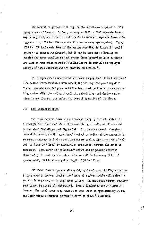
The laser derives power via a resonant charging circuit, which is discharged into the laser via a thyratron firing circuit, as illustrated by the simplified diagram of Figure 2-2. In this arrangement, charging current is drawn from the power supply output capacitor at the approximate resonant frequency of L1-C1 (the diode blocks oscillatory discharge of C1), and the laser is "fired" by discharging the circuit through the gated-on thyratron. Each laser is individually controlled by pulsing separate thyratron grids, and operates at a pulse repetition frequency (PRF) of approximately 10 kHz with a pulse length of 30 to 100 ns.
Individual lasers operate with a duty cycle of about 1:1000, but since it is presently unclear whether the lasers of a given module will pulse together, in sequence, or in some other pattern, the HVPS peak current requirement cannot be accurately determined. From a dissipated-energy viewpoint, however, the total power requirement for each laser is approximately 25 kw, and laser circuit charging current is given as about 4.2 amperes.
2-2
AC POWER
J
r LASER FIRING CIRCUIT L l
" I
GRID PULSE THYRATRON i & I
i i-WAr*
LASER / I I
Figure 2-2. HPVS Load Circuit
For the purpose of this study, the laser load will be tread ' as a fixed resistor dissipating 25 kw at 6 kvde, although it is recognized that future specification of an aggregate load duty cycle might reduce the power level somewhat. (Actually, the laser effective load resistance goes up at lower operating powers, so the full-power assumption of this study represents a worst case.)
The laser load circuits require regulated DC voltage at 6 kv + 2$ at normal full-power operation and individual lasers require adjustment of the 6 KV level over a + 10? range for system balanuing purposes. Moreover, the thyratrons are quite temperature sensitive and are notorious for spurious firing before they are "warmed up." Therefore, the HVPS output oust be adjustable from 0 to 6 kv so that the thyratrons may be gradually brought on-line during a warmup period. Thyratron spurious firing also results in a common fault mode, wherein the thyratron conducts in a sustained manner (termed "blooming11) thereby shorting the power supply.
These several reasons argue for a HVPS Modulator/Regulator using a grid controlled vacuum tube for DC output voltage regulation and control during faults. At this time it is uncertain that voltage control response times clearly require the fast-acting vacuum tube (other series devices might provide fault protection), but for the purposes of this study the need for a grid-controlled tetrode vacuum tube Modulator/Regulator feeding each laser load is assumed. Section 6 discusses other options that oould be used.
2-3
2.3 Power Line Characteristics
The Laser HVPS Systems will operate from the commercial AC power grids at three-phase voltages consistent with the KVA rating of the total HVPS load. For individual HVPS's rated at 25 kw output, AC power would probably be connected at the 480-volt level. For combined load scenarios, as discussed in Section 1, AC voltages would be set at the 13.8 kv or higher level.
For this study, primary line voltage is assumed to hold constant +2.5J. Also, the power grid feeding the power supplies is assumed to represent a zero-impedance source. For this reason, power supply input transformers must be designed to provide appropriate current limiting series impedance, and protective switching must be sized with interrupting capacities that are eonsistant with direct power grid feed.
Although the HVPS power source is assumed to be infinitely "stiff," it is recognized that a typical isotope separation facility will utilize large co-located electron-beam power supplies that may produce line regulation disturbances. Future studies should investigate this contingency and provide appropriate design compensation.
2.1 HVPS Specification
Table 2-1 lists a number of specificatior. parameters for the Laser High-Volta^ Powtr Supplies as they are known now. In many cases, these specifications represent assumptions made to simplify the great number of variable effects on the design estimate, or because the process development has not yet established the most c'esirable system arrangement. Future studies should refine the specification and determine resulting impact on the design.
2-k
Table 2-1. Laser HVPS System Specification
Parameters Value 1. HVPS output voltage 1. 6 lcvdc + 2?* 2. HVPS output current 2. 4.2 amp, average 3. HVPS output power 3. 25 kw, average ii. HVPS output ripple 4. Less than 2? 5. HVPS load duty cycle 5. TBD 5. HVPS load impendence 6. Resistive (assumed) 7. Lasers per laser chain 7. 5 to 8 8. No. of lasers per HVPS 8. One 9. Output voltage adjust, range 9. + 10? at full load** 10. Warmup adjust, range 10. 0 to 6 kvdo (at reduced
current) 11. Load wannup time 11. 15 minutes (assumed) 12. Laser PRF 12. 10 kHz 13. Laser pulse duration 13- 30 to 100 nsec l«. Laser pulse rise time 14. Undetermined 15. Load regulation range 15. 3.6 to 25 kw 16. Load regulation reponse time 16. TBD 17. HVPS input voltage 17. 13.8 kv or 480 vac,
3-phase, 60 Hz 18. Input line regulation 18. + 2.5? in ' 7 * Power input source impedance 19. Zero 20. No. of lasers per facility 20. 1000 (assur ) 21. System control interface 21. TBD 22. Laser MTBF 22. 150 hours 23. Laser mean-time-to-repair 23. 5 minutes 24. ^vwuli plant availability 24. 98? 25. I'VPS Transformer/Rectifier section MTTR*** 25. 5 minutes 26. HVPS Kodulator/Regulator section MTTR»*» 26. 5 minutes
•Regulation specification applies only during full power oper tion.
Regulation during varmup operation assumed to be unimpo tan' .
**The baseline HVPS design of Section 3.0 assumes a fixe' DC output of 6 kVdc.
***MTTR defined as mean-time-to-replace for the HVPS section?.
2-5
3.0 CHARACTERISTICS OF THE HIGH-VOLTAGE POWER SUPPLY
3.1 The Bjsellne Design
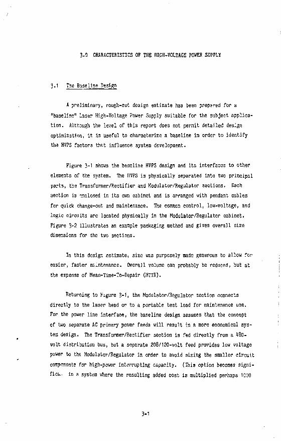
A preliminary, rough-cut design estimate has been prepaid for a "baseline" Laser High-Voltage Power Supply suitable for the subject application. Although the level of this report does not permit detailed design optimization, it is useful to characterize a baseline in order to identify ths HVPS factors that influence system development.
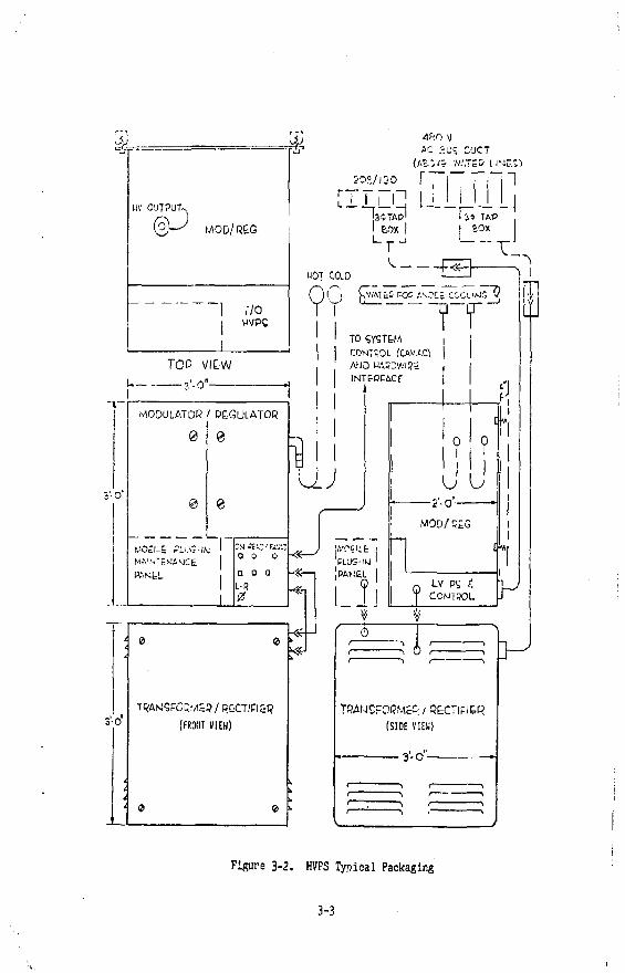
Figure 3-1 shows the baseline HVPS design and its interfaces to other elements of the system. The HVPS is physically separated into two principal parts, the Transformer/Rectifier and Modulator/Regulator sections. Each section is inclosed in its own cabinet and is arranged with pendant cables for quick change-out and maintenance. The common control, low-voltage, and logic circuits arc located physically in the Modulator/Regulator cabinet. Figure 3-2 illustrates an example packaging method and gives overall size dimensions for the two sections.
In this design estimate, size was purposely made generous to allow for easier, faster maintenance. Overall volume can probably be reduced, but at the expense of Mean-Time-To-Repair (MTTR).
Returning to Figure 3-1, the Modulator/Regulator section connects directly to the laser head or to a portable test load for maintenance use. For the power line interface, the baseline design assumes that the concept of two separate AC primary power feeds will result in a more economical system design. The Transformer/Rectifier section is fed directly from a 180-volt distribution bus, but a separate 208/120-volt feed provides low voltage power to the Modulator/Regulator in order to avoid sizing the smaller circuit components for high-power interrupting capacity. (This option becomes signifies... in a system where the resulting added cost is multiplied perhaps 1000
3-1
480V 3 G\ 6 0 HZ
DISTRIBUTION PANEL BOARD
3SKVA * ,N_
' / •
TRANSFORMER RECTIFIER SECTION
J
HV
CONTROL MODULATOR/REGULATOR SECTION
FLOAT iNG DECK
LOGIC
SCREEN PS
DVR/IA FEEDEACK
AMPS
208/120 V 3 0 , G 0 H 2
LOW-POWER DISTRIBUTION
X. y -i _ .
I 25KW .! LASER, j HEAD -
\ I TEST ,J I LOAD
CONTROL. SECTION LV POWER &. LOGIC
MOBILE MAINTENANCE *. DIAGNOSTIC
CONSOLE
HARD WIRE EXTERNAL "INTERLOCK F O ^ SAFETY
I
I I
| MANUAL ,CONTROL
CAMAC SYSTEM
INTERFACE
]
I
-TIMING -ON/OFF -PULSE -MONITORS/FAULTS -WARM UP SEQUENCE - INTERLOCKS
rIGUP.E 3 - 1 . HVPS BLOCK DIAGRAM
& • &
T&
HV OUTPUT-*
@J
,70 WVPS
JO?./120 T
3CTAP1
480 V AC SU? C'JCT
(AS. -J /& W.'.TEO L I N c . ^
l34> TAP I SOX
V . rl
MOT COLD • • « -
"̂
9 !, ; /AT£S r-os . ' /OC; COQLIMC 9
Q"
TCP VI&W — 3'-0"
MODULATOR / REGULATOR
0
0
MO£i:-& Pi. OS-IN NA'STENAUCfc
PAMtL
0 0 0
L-8 0
TO SYSTEM COMTpOL (CAt/.AC} AWO HAKC/. 'H?£
INTtOCACf 1
UJ
3-0 TRANSFORMER / (JGCTICl&R
(FMT VIEW)
PLUS-IW ' |PAt-.&L i
T
f. a..
? ? J I1
-2'-0"- '
M0D/9£G
n LV PS C, J CONTROL.
*».
¥ * f ° — , 1 r—
i f ° A ' \
TRAMS
(SIDE VIEW)
IFI&R
' '
'
Figure 3-2. HVPS Typical Packaging
3-3
times.) The separate feed will also permit Modulator/Regulator troubleshooting of low-level circuits without energising high power, and is thus safer. Moreover, the arrangement lends itself to other scenarios involving common Transformer/Rectifiers, as discussed in Section t.
3.2 Vacuum-Tube Modulator/Regulator
A simplified schematic of the baseline Modulator/Regulator is shown in Figure 3-3- Since the lasers are water-cooled, a water-cooled tetrode has been chosen for the baseline design and common water cooling systems may prove feasible in later design.
The 1CW25,0C0A tetrode will sustain the applied voltage with good margin and has much more anode dissipation capability than is required. Its design limitation is found in its grid current characteristic in this application. For the peak anode current expected, the tube operates close to the positive grid current region, and for this reason, the choice of this tube should be reexamined as peak load current requirements are better understood. Also, the tube nay operate close to its screen dissipation limit for swings to low values of anode voltage, and careful load line analyses should be performed for this usage, after load regulation limits are better defined. For this study, however, the 4CW25.000A is typical of the Modulator/Regulator tubes that can be selected. (The baseline design assumes a special version of the ilCW25,000A, having pigtail filament ±eads to avoid the cost of a tube socket.)
The Modulator/Regulator utilizes typical floating-deck construction, with a filament and other supplies isolated at the high-voltage level by a common isolation transformer. Grid drive and monitor signals are coupled to the floating deck by optical links. The tube controls output voltage via feedback amplifier loops, although the consideration of response time and performance of these loops has been outside the scope of this study.
3-1
Tf?AJ-J5POPMER - P E C T | F I E P <sE.e-rioivi
T p A f J C C O O M E R - R E C T l C i e p
C O O L I U G t V / A 7 E J 3 L O O P (•4 G P M €> B P S I )
The baseline HVPS design assumes that an individual Transformer/ Rectifier is required for each 25 kW load. (In Section k, alternative scenarios are discussed that utilize other Transformer/Rectifier arrangements.) In Figure 3-l|, a common-core, 6-phase transformer utilizing delta-wye secondaries and a four-wire wye-connected primary is shown, connecting to a conventional 12-pulse, 6-phase, full-wave rectifier. The design assumes that all current-limiting impedance mist be provided by the transformer, and a minimus equivalent impedance of 1$ has been specified. The balanced, common-care transformer and 12-pulse rectifier surpresses theoretical ripple to 1J, which helps to minimize filtering requirements. Ripple frequency is 720 Hz with this arrangement.
The 1 /if filter capacitor has been selected to provide adequate current to the load within the regulation specification of 2?, and under the resistive load conditions assumed. Should later load studies identify a higher peak current requirement, this selection should be reconsidered. Similarly, the bleeder resistor has been provided for safety and to help control output voltage during no-load operation. No-load to full-load regulation as currently specified is limited to 3-6 minimum output power, but if this value is reduced the bleeder circuit design should also be reexamined.
3.'* Control Interface
Referring again to Figure 3-1, the HVPS Block Diagram, it is seen that common control circuitry serves both the Transformer/Rectifier and Modulator/ Regulator sections and incorporates direct, hard-wire interlock circuits for equipment and personnel safety. Other control and monitor interfaces have been reduced to a minimum for economy. For example, front panel meters and controls are eliminated to reduce cost, except for those minimal disconnect switches needed for maintenance safety.
Manual controls for each HVPS are extended to a remote location foi convenience in controlling the system from a common point. For maintenance and trouble diagnosis, a portable maintenance console is suggested. This console should be installed into each HVPS when needed, but only a few would be required Tor the complex of 1000 HVPS's, thus reducing system cost.
The norral control and monitoring interface to each HVPS would connect via a distributed processor-controlled digital bus, using the usual CAMAC system control arrangement. This technique permits centralized automatic control and monitoring of the entire process facility and is judged to be the or y practical method for such a large plant. The CAMAC interface would provide for the usual control and monitoring functions but would also permit automatic programming of warmup sequences and special operational modes that require synchronism and coordination of all the HVPS's and lasers.
3.5 HVPS Power Estimate
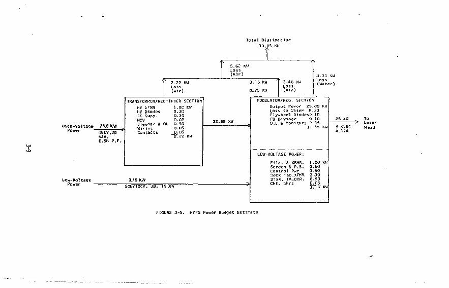
An initial estimate of the baseline HVPS power requirement has been made and Figure 3-5 gives a summary of the resulting power budget. The chart is in flow diagram form and shows that the 25 kw output is generated from two AC inputs totaling about 39 kva, and that about 11 kw is expended as loss.
This total dissipation is divided between air and water-cooling systems, assuming that the vacuum tube employs a water-cooled anode. Other circuit losses are distributed throughout the HVPS and it is more practical to assume air-cooling for these dissipations. If possible, air-cooling should occur through cabinet air convection avoiding the reliability problems associated with 1000 small cabinet blowers, but the practicality of convection cooling cannot be confirmed until ambient environmental conditions are established. If forced air becomes necessary, it may be possible to use a common source of "house" air for flushing purposes.
The estimate of total power required is conservative, and the relatively low overall efficiency (about 61$) is due principally to the large tube drop (about 2 kv) assumed for regulation snd control. A more extensive analysis
MODULATOR/KEG. SECTION Ou tpu t Power 25 .00 KW Loss t o Water 8 .33 F l ywhee l DiodesO.10 FB D i v i d e r 0 .10 0 , 1 & Kon1tors_0_._05_
33 .50 KW
LOW-VOLTAGE POWER:
F l l n . & XFMR. Screen 8 P.S. C o n t r o l Pwr Deck iso.XFISR B i a s , IA.DVR. C k t . Bkrs
6 XVDC 4.17A
To Laser Head
FIGURE 3 - 5 . HVPS Power Budget E s t i m a t e
of load operation and duty cycle may allow a reduction in tube drop and a consequent improvement in operating efficiency and power loss.
3.6 Baseline Cost Estirates
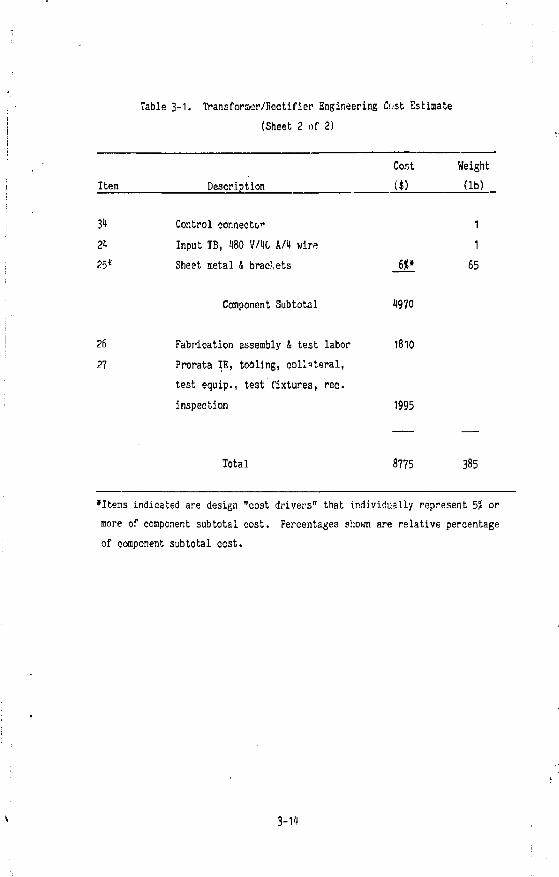
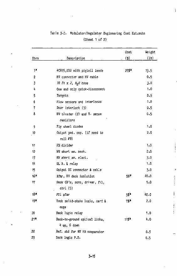
Tables 3-1 and 3-2 present rough-cut, engineering cost anc" weight estimates for the two main sections of the baseline Laser High-Voltage Power Supply. The estimates were made on the basis of 1000 -'dentica1 '5 kw HVPS's configured as shown in Figure 3-2. Estimates indie ' r.he 1O0 HVPS's can be produced for about $18.7K each for a total system prict of $l8.7M. The tabies provide detailed parts lists for those components making up the estimate, and show separate costs of $8775 and $9880 for the Transformer/flecti-fier and Modulator/flegulator sections, respectively. Additional costs for incorporating these baseline equipments into an operational facility are discussed in Section 5.
The following qualifications apply to the cost estimates:
1) The cost estimates shown in this report are engineering estimates only, made for the purpose of establishing trends and trade-offs in system design. The estimates do not in any way constitute an offer to sell equipment and/or services by Rockwell International at the prices shown.
?) All estimates are given in FY 1979 dollars. Appropriate escalation factors for future application should be applied.
3) The estimates shown in the tables are for recurring, production costs only. Non-recurring design and/or prototype costs, and costs involving quantities lower than 1000 are not included,
4) Production quality assurance and normal factory testing into simulated loads are included in the estimates. However, the cost of load simulators is not included.
3-10
5) The cost of customer data, including schematics, parts list, technical and instruction manuals, and training is not included in the estimates.
6) The additional equipment needed to distribute power to the baseline HVPS's is not included in the tables. However, these costs are addressed in Section 5.
7) Material and labor for installing and verifying the operational integrity of equipment in the plant facility are excluded from the estimates,
8) No water cooling components other than those supplied as part of the Modulator/Regulators are included in the estimates. This exclusion pertains to pumps, piping and valves, deioniaers, stills, flowmeters, cleanup loops, surge tanks, electrical interlocks, etc.
9) Transmission line connections to the laser head loads are not included.
10) The cost "f 180 and 120-volt circuit breakers of HVPS power input feeds are not included in the cost estimates. It is felt that these components can be more conveniently installed at other locations in a main panel board or more perferably as a part of a bus-duct distribution system.
11) Vacuum-tube filament life can be significantly extended by reducing filament voltage by 5 or 1CJ, provided that line voltage regulation permits consistent operation at a predictable educed voltage. Separate voltage regulators (Sola, electronic regulation, etc.) can be provided to maximum tube life, but these regulators are excluded from the cost estimates.
3-11
12) Transformer/Rectifier filter components iiave been minimized to reduce cost and increase reliability. It is recognised, however, that the frequencies of leakage reactance ringing due to rectifier commutation could approach the resonant frequencies of the laser head thyratron charging circuits, and later design changes to avoid this potential problem could increase HVPS costs.
13) It has been assumed that Eiinae would supply a special version of the 4Ctf25,000A tube, with pigtail leads to eliminate the cost of a tube socket, at no additional charge, if production applications of 1000 were involved.
I'D Although the simplified circuit of Figure 3-3 shows a separate isolation transformer for the Modulator/Regulator floating deck, it may be possible 1.0 ̂ sibine this function with the modulator filament transformer at reduced cost.
15) All costs shown in the tables are unconfirmed estimates. It may be possible to realize certain cost reductions by competitive purchase of special components and volume buys of catalog parts.
16) The cost of remote manual controls, the mobile maintenance and diagnostic console, and the CAMAC system interface is excluded from the estimate.
17) Cost methodology consisted of making rough engineering estimates based on Rockwell International's experience in the design and manufacture of similar equipment and systems. Because of the limited scope of the initial study, costs have not as yet been substantiated through vendor quotations or formal manufacturing cost estimates. Similarity to other equipment, however, helps to justify the accuracy of the estimates. In the estimate tables, all costs shown are fully ourdened.
3-12
Table 3-1. Transformer/Rectifier Engineering Cost Estimate (Sheet 1 of 2)
Coat Weight Item Description ($) (lb)
1 Connector, U80 V/10 A pendant 2
cable plug A jack (Hubble)
2 10 ft stranded flex cable, 10 A H
3 16 No. 1 crimp lugs 1
4» 3-phase vac sw, U80v 29J* 15
5 Surge suppress cap. 15
6 3-phase current xfnrs (not 3
instrument type)
7 3-phase thermal CB (small) 1
8* Rect. xftar, 32 kva, 180v, 6 kv, 23** 200
') A, 12 pulse
9» 12-pulse rect. set with RC 9? f 12
suppressor
10 DC RC ring oup. 2 11 Minimal filter reactor, 0.2 Hz, 1 A, 20
6 kv 12 Reactor MOV 1 13 R. cap. surge limit 4 mtg 3 It 10 kv, 4^f filter cap. 20 15 Bleeder, VM mult, 4 series R 1 16 Eleo. oper. HV short sw 3 17 Mech. door short sw. (fab) 1 18 Microsw. door. int. sw. 1 19 Output HV connector, RG 89/RG 17 1 20 O.L. R, O.L. Relay 1 21 Control Relay 1 22* Misc. wire, lug, parts 6?* 10
3-13
Cost Weight
($) (lb)
1
1
6** 65
Table 3-1, Transforner/Fectifier Engineering Cost Estimate (Sheet 2 of 2)
Item Description
31 Control connecto" 21 Input TB, 180 V/1G A A wire 251' Sheet metal & brackets
•Items indicated are design "cost drivers" that individually represent 5? or more of component subtotal cost. Percentages shown are relative percentage of component subtotal cost.
3-11
Table 3-2. Modulator/Regulator Engineering Cost Estimate (Sheet 1 of 2)
Cost Weight Itcra Description (« (lb)
1» 1CN25.000 with pigtail leads 27*» 13-5 2 HV connector and HV cable 0.5 3 10 ft x 2 , H 20 hose 3-0 1 One end only quick-disconnect 1.0 5 Targets 0.5 6 Flow sensors and interlocks 1.0 7 Door interlock (3) 0.5 8 HV bleeder (2) and V. sense
resistors 0.5
9 Fly wheel diodes 1.0 10 Output pad. cap. (if need to
roll FB) 2.0
11 FB divider 1.0 12 HV short sw. mech. 2.0 13 HV short sw. elect. 3.0 11 OL R. 4 relay 1.0 15 Output DC connector 4 cable 3.0 16* Xfmr, HV deck isolation 5** 10.0 17 Deck CB's, scrn, driver, fil,
•Items indicated are design "cost drivers" that individually represent 5? or more of component subtotal cost. Percentages shown are relative percentage of component subtotal cost.
3-16
1.0 LOAD SCENARIOS
1.1 Introduction
The baseline Laser High-Voltage Power Supply described in Section 3 can be connected to the 1000 laser3 of the process facility in several ways. These connection alternatives, called load scenarios, have an impact on overall system cost, but each scenario involves some compromise in system operational characteristics.
The paragraphs tha, follow define.three load scenarios that were considered in this report, and show how certain specification changes can permit the use of conmon equipment for portions of the power supplies with resultant cost savings. The scenarios are arranged in terras of increasing complexity of load voltage control. For reference, Scenario C defines the use of 1000 totally independent (baseline) HVPS's.
1.2 Scenario Definitions
The following definitions apply to the three cases studies. In each case a figure accompanies the definition to illustrate the connection options. Table 1-1 compares the three scenarios and their technical characteristics.
1.2.1 Scenario A (Figure 1-1)
Each laser load will be independently regulated. However, all 1,000 modules will require the same voltage - approximately 6 kvdc + 10J. That is, each is independently controlled and regulated, but all will operate somewhere in the range of 6 kv + 10J.
1-1
Table 1-1. Load Scenario Comparison
Scenario Laser Heads
per Regulator Regulators per Transformer/ Rectifier
Quantity of Trarsformer/ Fectifiers
Laser Head Voltage
Load Assumption
Warmup Assumption
250 6 kv + 10* Similar None
250 0-6 kv • 10% Similar Common
1,000 0-6 kv + 10% Dissimilar Individual
To site main sub 8 metering 13 .8 kv
* >r> K-
Switchgear
by Rockwell
"< To -i Other : -5 Mod/Reg
by Others
1 Control. Modulator Regu-la.tor
AP6kv l_ 25 kw ^f
LASER HEAD
Common Transformer/ Rectifier, 8.5 MW
Figure 4-1. Scenario A — Pov/er Supply for 250 Laser Loads (Typical 4 Times)
1.2.2 Scenario B (Figure 1-2)
Us in Scenario A, each laser load will be independently regulated. However, they can be at any voltage from 0 to 6 kv as long as they remain within a 10? spread of each other. That is, if the selected voltage is 1 kv, all loads must operate within a 3.6- to 1.1-kv range.
1.2.3 Scenario C (Figure l|-3)
The lasers are independently regulated and controlled and do not behave in unison in any fashion. That is, one or more lasers could be at zero volts while one or more are at 6 kv, with others at any voltage between thesi two extremes.
1.3 Optimum Scenario
The sctnarios discussed in Section 1.2 were chosen to present the limits of a range of possibilities for operating 1000 lasers. Scenarios A and B show conmon DC feeds of groups of 250 lasers, and Scenario C assumes a separate HVPS for each laser.
While Scenario B is probably the best choice of those examined, it is not necessarily the optimum arrangement. For example, if the plant utilizes 10 laser modules, then the HVPS's should probably be arranged in ten groups of 100 for a more logical power distribution and to permit a common raainten-ance philosophy, Although outside the scope of this first study, selection of 3 more optimum load scenario is recommended.
1-1
To s i t e main sub X meter in'
13.8 kv
by Rockwell by Others
~l
LASER HEAD
Common Trans fo rmer /Rec t i f ie r . With Var iable I npu t , 3.5 MW
Figure 4 -2 . Scenario B — Var iable Voltage Power Supply for 250 Laser Loads (Typical 4 Times)
TQ S i t e Main _ Sub & Metering
:13.8 kv
28 l l rn ' t Sub 1.333 mva-
by Rockwell
28 F1tr Control |Center (1.333 mva)
Hi-Voltage Power Supply
by Others
LASER HEAD
[Figu.-e 4-3. Scenario C — One High Voltaoe Power Supply per Laser Load
5.0 SYSTEM OPTIMIZATION
5.1 Possible Variations
In simplified single line diagram form, Figure 5-1 illustrates the elements required to convert and condition the 13.8 kvac voltage to the required 6.0 kvdc. The drawing corresponds to Scenarios A or B of Section k. Since it has been assumed that 1,u00 separate Modulator/Regulators will be required, it is clear that Node A (the DC bus) must fan out to 1,000 legations. Key questions related to system optimization and cost are:
1) What is the detailed definition of the load requirement (pulse length, PRF, regulation, etc., and of the AC line characteristic voltage, source impedance, transients, etc.), as these definitions affect HVPS design options?
2) Is rapid response regulation really needed? Could hard switches (SCR's, thyratrons, or direct-connected switches) replace vacuum-tube Modulator/Regulators?
3) Is pre-regulation (variable transformers, SCR's, etc.) required? Can pre-regulation be used in conjunction with Modulator/Regulator options (see Section '.3) to produce a more optimum system design?
1) What is the optimum arrangement of prime power distribution (AC breakers, Transformer/Rectifiers, etc.)?
5) Is it necessary and/or preferable to install any form of voltage control ahead of Node A; i.e., incorporated in the Transformer/ Rectifier or on the AC side of the transformer?
6) Can common regulation be implemented? Can multiple laser loads be powered by the same Modulator/Regulator, as shown in Figure 5-1?
5-1
7) Can cocmon regulation be implemented on the primary side of the power supplies rather than at each individual load?
8) Will the duty cycle of the individual lasers permit a reduction in peak current required from the HVPS, ai.d/or a reduction in the average power rating of 25 kw for each HVPS?
9) Can the laser firing circuit and resonant charging circuit be redesigned to afford some degree of regulation within itself?
r •"""""ll1)
60HZ1 "-*)
AC BREAKER [ j
TRANSFORMER RECTIFIER
I 1
\ ! i i POSSIBLE .MULTIPLE
LASERS
MOD-REGULATOR LASER (LOAD)
999 ADDITIONAL REGULATORS AND LOADS
Figure 5-1. Elements Required to Convert 13.8 kvac to 6.0 kvdc
5-2
5.2 Load Scenario Considerations
Several factors should be addressed in considering the load scenarios of Section It.
In Scenarios A and B, with Modulator/Regulator outputs set at 6 kv + 10?, the DC level at Node A would be approximately 8 kv, for a Modulator/ Regulator drop of 2 kv. This vacuum-tube drop is a reasonable value for tetrodes operating with a screen voltage of "500 volts, and would provide a normal output of 6 kv with a range of +10$. With a fixed 8-kv input, the tube can be arid-controlled to reduoe output voltage to zero, of course, Increasing tuD? voltage drop, but at a decreased output current.
Scenario B add" pre-regulation i:i the form of tap switching at the common transformer so that the Transformer/Regulator can operate at reduced KVA for the lower output voltages. In Scenario B, a Node A DC voltage range of approximately 1 to 8 kv is assumed.
In Scenario C the common transformer is eliminated. Since the aggregative load behavior cannot assure that all outputs would be within a reasonable spread as in Scenarios A and B (+10?), the equivalent of Mode A within each HVPS is set at 8 kv in all cases to assure the maximum output of any regulator (6.6 kv) at all times. Consequently, some regulators nay be required to deliver 1 kv or lower output while others are operating at the maximum nominal rating of 6.6 kv.
Fig'ire 5-2 illustrates how the total 25-HW will be broken down for Scenarios /. =nd B. The tapped transformer depicted at the top would only be applicable for Scenario B, where It is preferred to bring the outputs up simultaneously from approximately 1 kv. For each 8.5-MW load, a 500-mva rated, 15-kv class, 3-1/2 cycle, 1200-A frame size vacuum breaker switchgear assembly could be used to apply the 13.8 kv to the primaries of each 6-phase transformer. (Scenario B will require tapped transformers, as discussed.)
5-3
I3.8KV ' 6 0 H Z "
„ fy ^ ^
i •w*.
TO 250 REGULATORS
TO 250 REGULATORS
M r TO250 I ^ R E G U L A T O R S !
MOD.-REG.
LASER (LOAD)
•i)
TOTAL OF 2.50 LOADS PER BRANCH SECTION
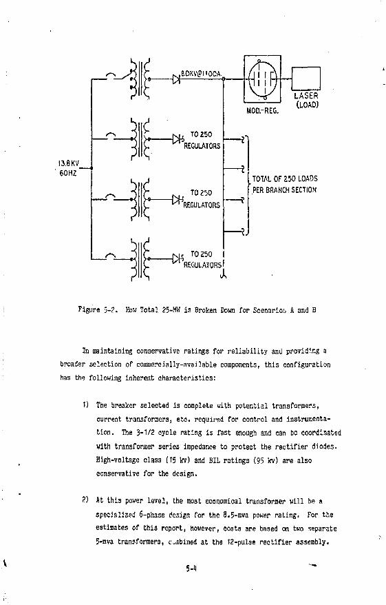
Figure 5-2. How Total 25-Mtf is Broken Down for Scenarios A and B
In maintaining conservative ratings for reliability and providing a broader selection of commercially-available components, this configuration has the following inherent characteristics:
1) The breaker selected is complete with potential transformers, current transformers, etc. required for control and instrumentation. The 3-1/2 cycle rating is fast enough and can be coordinated with transformer series impedance to protect the rectifier diodes. High-voltage class (15 kv) and BIL ratings (95 kv) are also conservative for the design.
2) At this power level, the most economical transformer will be a specialized 6-phase design for the 8.5-mva power rating. For the estimates of this report, however, costs are based on two separate 5-mva transformers, cabined at the 12-pulse rectifier assembly.
5-4
3) The 8-kvdc voltage at Node A is relatively high, and in order to provide this output at a current level of 1100A, the design requires a special design 6-phase, full-wave rectifier bridge.
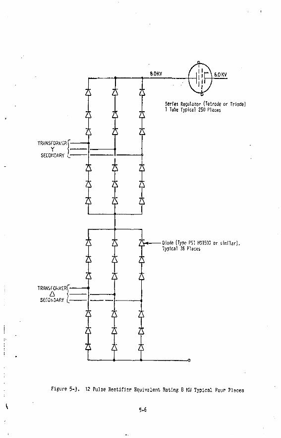
Figure 5-3 is a further illustration of the rectifier section. Each bridge would require at lease three diodes in series per leg, as shown. Selection of a device such as the PSI HD1500 or equivalent are readily available from several manufacturers. The "hockey puck" configuration of the device provides the greatest surface area for either forced air or water cooling.
The nominal rating of this diode is 2500v at 280OA, and the rectifier section would thus have an approximate current safety factor of 2.5, assuming a 30? margin on current rating (i.e., 2000A) the resultant power rating of the rectifier section would be approximately 12 MW. Thus, with very little additional cost, a Transformer/Rectifier section as described would be extremely rugged and reliable while using standard industrial components.
As illustrated in Figurt 1-3, load Scenario C required 1000 individual HVPS's each operating from f80v power. Ahead of the power supplies are 13.8 kv/180 kv, 3-phase transformers and a network of selector switches and breakers to distribute 480v, 3-phase, 60 Hz AC power to each power supply. The disadvantage of this soenario is in the redundancy of the transformer con-figuratijns. It is necessary to transform the entire 36 mva of power twice, first at the twenty-eight 13.8 kv/180 kv step-down transformers and a second time at each of the 1,000 HVPS transformers. More importantly, use of 1,000 discrete transformers, each capable of 36 kw, and twenty-eight 1 mva unit substations, creates a much higher cost than with Scenarios A and B, and provides the incentive for some forn of combined operation. However, the advantages of Scenario C are also quite clear:
5-5
8.0KV
Series Regulator (Tetrode or Triode) 1 Tube Typical 250 Places
TRANSFORMER Y
SECONDARY
•Diode (Type P5I HD1500 or similar) Typical 36 Places
1) When it is assumed that Scenarios A and B are not indicative of actual system requirements.
2) The ability to interrupt power at the low AC voltage level (480v) to each load with small, conventional circuit breakers.
3) The redundancy and flexibility of the independent power supplies, and the positive impact on system availability.
It should be noted that the nominal 13.8 kv referenced in this report as the serving voltage is typical of conventional voltage systems ranging from 11,160 to at least 30,000 volts for the power levels considered for this application. Operation of the power supplies at 30,000 volts would facilitate a coaraon voltage distribution system in conjunction with other loads intended to operate at 30,000 volts. Advantages gained by using 30,000 volts would be offset by an increased cost in equipment (power supply transformers and switchsear) and the additional safeguards needed to assure personnel safety.
5.3 Laser HVPS System Cost Estimates
Table 5-1 provides a cost estimate comparison between the three approaches discussed in this report. The following qualifications apply to the table:
1) The cost estimates shown in this report are engineering estimate*-only, made for the purpose of establishing trends and trade-offs in system design. The estimates do in no way constitute an offer to sell equipment and/or services by Rockwell International at the prices shown.
2) All estimates are given in FY 1979 dollars. Appropriate escalation factors for future application should be applied.
5-7
3) The costs for the baseline Transformer/Rectifiers and Modulator/ Regulators are derived from Tables 3-1 and 3-2 of this report. The qualifications to those estimates discussed in Section 3.6 apply here as veil.
1) E?sign basis for Scenarios A and B is 1 Transformer/Rectifiers, each capable .of delivering 8.5 MW.
5) Add $120,000 for each Transformer/Rectifier system added to Scenarios A and B. For example, if Scenario A used 20 power supply systems (instead of 4), add $1,920,000.
6) Add 15$ to total cost of each scenario for installation, interconnecting wiring and conduit.
7) Add i0< for installation of equipment outdoors.
8) Add 10J to total cost of each scheme for System Design Engineering and Project Management (assuming equipment design non-recurring effort has already teen accomplished).
9) Cost for QA, Construction Advance Procurement, and Surveillance are not estimated and not shown.
10) High-Voltage switchgear should be installed outdoors if practical. All other equipment may be installed indoors.
11) Modulator/Regulators should be installed within proximity of loads served. Separation distance between the Transformer/Rectifiers and the Modulator/Regulators should be kept at a minimum.
12) This report does not include cost estimates for control equipment required for system control and interface to CAMAC) processors.
5-8
Table 5-1. Laser HVPS System Coat Comparison
Figure Transformer/ Modulator/ Motor Total Percent of Scenario No. Switehgear Transformer Rectifier Rectifier Regulator Control System Cost Scenario C
The design approaches discussed thus far in this report are based on using a tetrode vacuum-tube Modulator/Regulator in a conventional series circuit, moderating the level of HVPS output and operating from a fixed-voltage Transformer/Rectifier. Sections k and 5 have applied this basic circuit in various system options and have provided cost estimates for the resulting cases.
It is important to understand, however, that the scenarios examined nay not represent the most optimum sysrem design. Many circuit alternatives could be introduced all having substantial impact on cost, size and weight, adjustment range and speed, and on system availability. In fact the best laser HVPS may be one that eliminates the series vacuum tube altogether and provides output variation through some other means.
The purpose of this section is to examine other circuit options that should be considered for the system. Although outside the scope of this first conceptual report, all options should be examined in greater depth before deciding on the most desirable system design as outlined in Section 7. Other circuit options are of two general categories: (1) Pre-Regulati i Options - those adjustments of relatively slow response time that are suitable for inclusion in the Transformer/Rectifier section, and (2) Modulator/ Regulator Options - those series-connected devices that can be used to quickly control output power.
6.2 Pre-Rpgulation Options
Several circuit options may be used to adjust HVPS output power by varying the AC input voltage within the Transformer/Rectifier section. These circuits, termed "pre-regulators," are described in the following paragraphs.
6-1
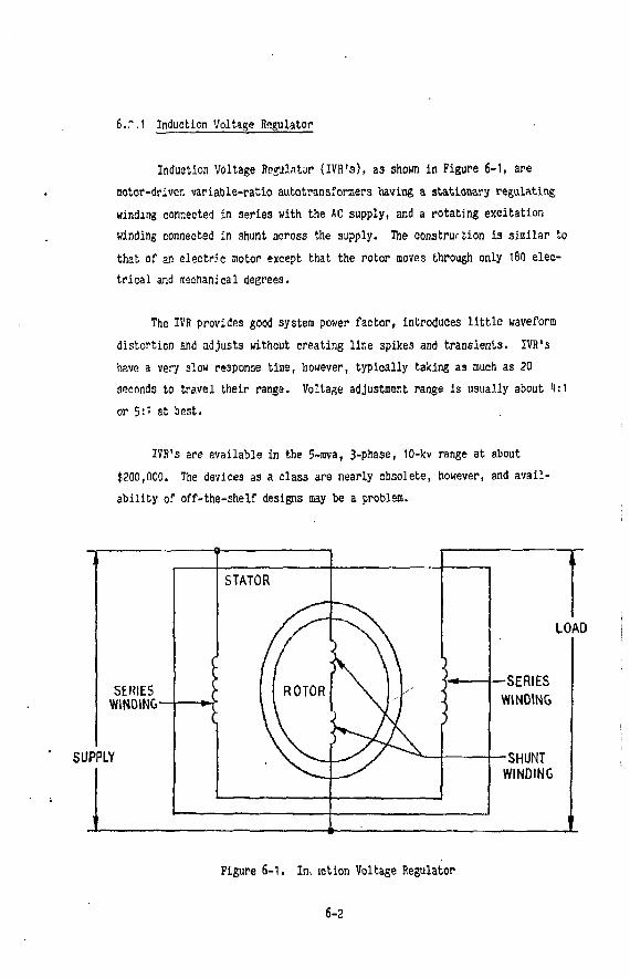
6.T.1 Induction Voltage Regulator
Induction Voltage Regulator (IVR's), as shown in Figure 6-1, are motor-driven variable-ratio autotransformers having a stationary regulating winding connected in series with the AC supply, and a rotating excitation winding connected in shunt across the supply. The construction is similar to that of an electric motor except that the rotor moves through only 180 electrical and aeehanical degrees.
The IVR provides good system power factor, introduces little waveform distortion and adjusts without creating line spikes and transients. IVR's have a very slow response time, however, typically taking as much as 20 seconds to travel their range. Voltage adjustment range is usually about i|:l or 5:1 at best.
IVR's are available in the 5-mva, 3-pnase, 10-kv range at about $200,000. The devices as a class are nearly obsolete, however, and availability of off-the-shelf designs aay be a problem.
SUPPLY
LOAD
Figure 6-1. In, sction Voltage Regulator
6-2
6.2.2 Saturable-Core Reactor
Figure 6-? shows a saturable-core reactor, consisting basically of two AC windings connected in series with the load. These windings are wound or. a common core with a DC control winding, which when energized partially saturates the core, decreasing the induction of the series winding and increasing current in the load.
When connected wi'/n suitable feedback circuits, the saturable reactor can act to produce constant output current (as contrasted with the IVR, which produces constant output voltage). Circuits employing saturable reactors exhibit relatively slow response times - faster than with IVR'3, but slower than circuits employing electronic controllers such as thyristors. Because of their operation near saturation, saturable reactors are non-1: ,iear devices and introduce line harmonics that can be disturbing to the electrical power system.
Saturable reactors are relatively low in cost. A 5-mva, 3-phase unit operating at the 8-kv level is available for about $50,000.
6.?.3 Tap-Changing Transformers
Transformer tap changing provides a common way to adjust power supply output voltage, and the technique will probably be used to provide course voltage adjustment in the Laser HVPS's. Transformer tap changers can be used with main rectifier transformers or with separate tapped autotransformers, as shown in Figure 6-3.
With these devices, tap changers can be motor-driven or can consist of a group of interlocked contactors. Variable autotransformers with sliding brushes are also available in sizes up to about 10 mva, but life In continous service is a problem and the devices are difficult to protect.
6-3
A/C SUPPLY
\ LOAD
SI w
A/C SUPPLY
Figure 6-2. Saturable Core Reactor
6-U
- O N
LINE HAPS LOAD
?POSITIONING MOTOR
TO CONTROL CIRCUIT
Figure 6-3. Tap Changing Step Voltage Regulator
6-5
Again, voltage adjust response time is very alow and although the larger units are relatively inexpensive (about $100,000), contact life considerations makes their use questionable where a continually-regulated voltage is necessary.
6.2.1) Thyristor Controller
Solid-state controllers using thyristors are commonly used instead of diodes in Transformer/Rectifiers to produce variable output voltage control. Alternate circuits utilize thyristors in series with transformer priaaries to produce effective voltage reduction by "phasing back" or "chopping" the AC wave into partial half-cycles (as in residential lamp dimmers).
Gate-controlled SCR's (silicm-controlled rectifiers, Figure 6-4) are common thyristor types used in power applications. Gate voltage control produces the solid-state equivalent of opening and closing a switch, except that once energized, the SCR must experience a load current interruption or reversal before returning to its "open" state.
Early SCR controllers suffered from spurious firing and lightning (and other) transient vulnerability, but the more elaborate gating and protective circuits now in use tend to minimize these disadvantages. When used in direct power input connections, however, SCR's create heavy line current harmonic distortion when phased-back substantially.
Power thyristors are in common use in high-voltage (up to 13.8 lev) AC applications and circuit complements of SCR's for 5-mva ratings are available for about $300,000. Because of its fast response time, the SCR is a good candidate for the Laser HVPS application. Pre-regulators using SCR's in combination with simplified Modulator/Regulators may offer the most economically attractive alternative to the baseline vacuum-tube Modulator/Regulator.
6-6
OANODE
(!) CATHODE
Figure 6-1. Silicon Controlled Rectifier
6.3 Modulator/Regulator Options
6.3.1 Tetrode and Triode Vacuum Tubes
The baseline Modulator/Begulator described in Section 3.2 of this report utilizes a tetrode vacuum tube with a water-cooled external anode, a ceramic body, and a single-phase thoriated-tungsten filament. The tube chosen, an Eisac Type 1CW25,O00A, is typical of a large family of power grid tetrodes available from several U.S. and foreign sources.
A similar family of power grid triodes is available from the sane sources, and a basic trade-off evaluaton between triodes and tetrodes should be made when choosing a tube for the Laser HVPS's. Many tubes of the two basic types can be purchased with either air or water-cooled anodes, and the larger tubes rcay also be fitted for vapor cooling.
6-7
The trade-off between triodes and tetrodes is basically a choice between the larger grid-driving power of the triode vs the need for a screen supply with the tetrode. The need for the additional (screen) supply is a particular disadvantage in floating-deck modulator schemes, but the triode may require larger and more complex drivers, thus reducing overall reliability. Although the tetrode normally operates without drawing grid current and requires less plate voltage swing for full output current, the added components of the screen supply may offset it3 advantages in favor of triodes when reliability studies of the floating-deck modulator are made. In either case - triodes vs tetrodes - total power consumed is similar.
A thorough tube-choice study should be made for Laser HVPS design optimization. It may be that zero-bias triodes, which require much less driving power yet preclude the need for a screen supply, may be the beat choice for this application.
6-3.2 Thyratrons and Thyristors
If the basic need in the Modulator/Regulator is to precisely control turn-on of output current and to interrupt the current in event of a fault (the modulator function), and if the regulator function of adjusting output power level can be accomplished by one of the pre-regulation options, then the series g«id-controlled vacuum tube can be replaced by a simple switch. Series-connected thyratrons, or their solid-state equivalents, the thyristors.. can perform this switching function.* Thyratrons are better suited for the higher-voltage applications where many series-connected SCR's would otherwise be needed.
•Series thyratrons were used in the Lawrence Livermore development models for the MFTF (Mirror Fusion Test Facility) Sustaining Neutral-Beam Modulators at 80 kv and 80 A, and alternative designs using SCR's were also built. See LLL Report UCID-17570, "80 kv Modulator Design and Operation," by Tom Kruckewitt (with Robert W. Kuenning), September 2 , 1977.
6-8
For applications where large -.umbers of Modulator/Regulators are
required, the use of SCR's as switching devices is attractive because they
require no filament power. (The baseline design uses a total filament power
of about 1 1W for the entire facility.) Thyratrons use filament heating as
do power-grid tubes, but required power is much less because the thvratrons
usually employ oxide-coated cathodes and heaters.
As discussed in Section 6.2.1, SCR's (and thyratrons) can be gated "on",
but once energized cannot be "turned off" without load circuit interruption.
This disadvantage can be overcome by using special shunting circuits, which
themselves may use active devices, that "ring off" r.he series switch. The
circuits can become rather complex, and resulting reliability relative to
the baseline vacuum-tube design should be weighed against filament power and
circuit regulation considerations.
Thyratrons and SCR's suffer" from a tenr'• :icy toward spurious, gating,\and
this factor, plus the temperature sensitivity of thyratrons, suggests that-!# \
simpler switching solution would be preferable.
6.3.3 Direct-Connected Switches —^——— «.
/ If the Laser HVPS regulation requirements can be met through preregu-
lation or through some other technique, the remaining justification for a series vacuum tube is the tube's ability to quickly open the circuit in the event of a load short. This "fault mode" protection is particularly important in the subject application, because each HVPS load involves a number of thyratrons that can be expected to experience sustained conduction (blooming) from tiite to time. In fact, thyratron blooming may happen so often that the event should be considered part of normal operation,' and provision of a series switch to avoid feeding unlimited energy into the shorted load is mandatory.
It is tempting to consider a simple, directly-connected vacuum switch for the function of load current interruption. Conceptually, the active series devices of the Modulator/Regulator (either vacuum tubes, thyratrons,
6-9
or SCfi's) could be replaced viith a simple vacuum switch to perforin the functions of load connection and fault interruption.
Actually, the circuit should probably use several vacuum switches for reduced voltage operation and/or "soft" starting through step-start series resistors. Rectifier surge protection to avoid transformer leakage reactance overshoots when switching the load under power should be included, and the circuit would probably need flywheel diodes to dissipate transient energy stored in the power supply filter.
Direct load switching is an attractive option that could yield substantial syste-n Improvements in terms of cost and reliability, if feasible. The key to its feasibility is a better understanding of the load regulation requirement. Modifications in the laser load charging circuit may considerably simplify the need for HVPS regulation, and could permit the use of much simpler Modulator/Regulator techniques and circuits.
6-10
7.0 RECOMMENDATIONS FOR FURTHER STUDY
This report has outlined several concepts for Laser High-Voltage Power Supplies, but has been limited to an early overview within the constraints cf the existing system definition. Before an optimized system can be selected, more detailed designs should be formulated based on vendor parts cost estimates and on a firm design plan for prototype hardware.
Accordingly, this section recommends additional areas of study aimed at producing a truly optimized system for Laser Isotope Separation. The suggested areas of study are:
1) Requirement Specification. Creation of a definitive load specification will help to narrow the options of system operational usage and may thus permit possible economies in the Laser HVPS System arrangement. For example, the ability to operate more than one laser from a single Modulator/Regulator will reduce system costs, and this option shojld be considered if determined to be feasible from the viewpoint of system load requirements. Elimination of the series-tube modulator/regulator should also be considered.
I) System Optimisation Guidelines. Guidelines for system optimization should be developed, to identify the most significant parameters of the Laser HVPS System and their relative importance. For example, the relative merit of cost (acquisition, operating, and total life-cycle cost), size, weight, operating efficiency, reliability, maintainability, system availability, etc., should be established on a quantitative basis,
3) Detailed Scenario Development. Several scenarios of Laser HVPS System arrangement should be evaluated in detail, and technical and cost parameters should be determined for each scenario under consideration. !
7-1
Selection of Optimum Design. A parametric trade-off analysis should be performed for each of the candidate scenarios, using the optimization guidelines previously developed. An effort should be made to quantitize the evaluation parameters whenever possible to permit an objective and justifiable selection of the optimized design.
Detailed Design Plan for Production Plant. A detailed design description of the Laser HVPS System hardware, together with confirming C03t estimates, should be produced for a future isotope separation production facility. This plan should be based on the optimum design selected in paragraph 1 above, and should be of sufficient detail to permit later hardware definition and procurenent.
Design Plan for Prototype System. A design plan should also be generated for prototype Laser HVPS System hardware intended as a feasibility demonstration of the selected system. Again, cost estimates should be included. It is anticipated that the feasibility equipment would represent only a portion of that required for the eventual production facility, with HVPS and Laser load quantities to be determined during the design plan effort.
NOTICE
Work performed inder the auspices of the US. Department of Energy by the Lawrence Liver-more Laboratory under contract number W. 7«5-ENG-18.
This report was prepared as an account of work sponsored by the United Stiles Government, Neither the United States nor the United Suits Department of Energy, nor any of their employees, nor any of their contractors, subcontractors, or their employees, makes any warranty, express or implied, or assui.ies any legal liability or responsibility for (he accuracy, completeness or usefulness of any information, apparatus, product or process disclosed, or represents that its use would not infringe privately-owned rights.
Reference to i company or product name does not imply approval or recommendation of the product by the University of California or the US. Department of Eneray to the exclusion or others that may be suitable.