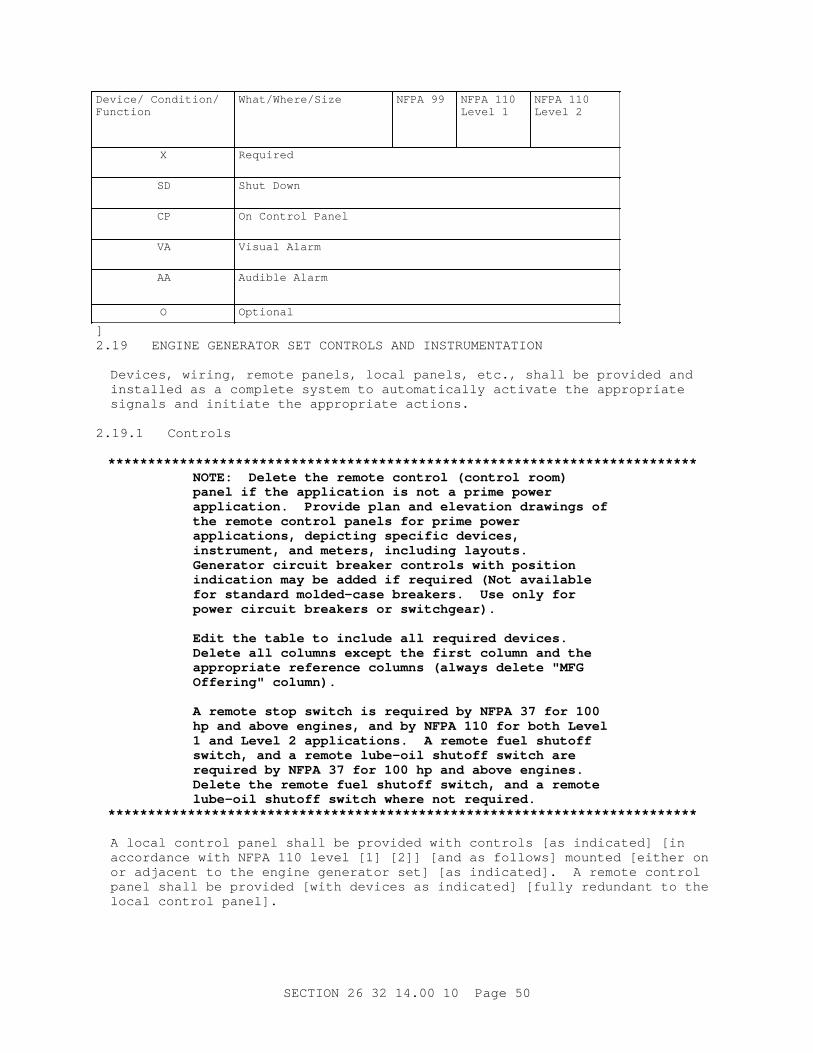
************************************************************************** USACE / NAVFAC / AFCEC / NASA UFGS-26 32 14.00 10 (February 2010) ----------------------------------- Preparing Activity: USACE Superseding UFGS-26 32 14.00 10 (October 2007) UNIFIED FACILITIES GUIDE SPECIFICATIONS References are in agreement with UMRL dated April 2018 ************************************************************************** SECTION TABLE OF CONTENTS DIVISION 26 - ELECTRICAL SECTION 26 32 14.00 10 DIESEL-GENERATOR SET, STATIONARY 15-300 KW, STANDBY APPLICATIONS 02/10 PART 1 GENERAL 1.1 REFERENCES 1.2 SYSTEM DESCRIPTION 1.2.1 Engine-Generator Parameter Schedule 1.2.2 Output Capacity 1.2.3 Power Rating 1.2.4 Engine Generator Set Enclosure 1.2.5 Vibration Isolation 1.2.5.1 Vibration Limitations 1.2.5.2 Torsional Analysis 1.2.5.3 Performance Data 1.2.6 Reliability and Durability 1.3 SUBMITTALS 1.4 QUALITY ASSURANCE 1.4.1 Conformance to Codes and Standards 1.4.2 Site Welding 1.4.3 Experience 1.4.4 Field Engineer 1.4.5 Seismic Requirements 1.4.6 Detailed Drawings 1.5 DELIVERY, STORAGE AND HANDLING 1.6 MAINTENANCE SERVICE 1.6.1 Operation Manual 1.6.2 Maintenance Manual 1.6.3 Extra Materials PART 2 PRODUCTS 2.1 NAMEPLATES 2.2 SAFETY DEVICES 2.3 MATERIALS AND EQUIPMENT 2.3.1 Circuit Breakers, Low Voltage 2.3.2 Filter Elements (Fuel-oil, Lubricating-oil, and Combustion-air) 2.3.3 Instrument Transformers 2.3.4 Pipe (Fuel/Lube-oil, Compressed-Air, Coolant and Exhaust) SECTION 26 32 14.00 10 Page 1
Transcript
**************************************************************************USACE / NAVFAC / AFCEC / NASA UFGS- 26 32 14. 00 10 ( Febr uar y 2010) - - - - - - - - - - - - - - - - - - - - - - - - - - - - - - - - - - -Pr epar i ng Act i v i t y: USACE Super sedi ng UFGS- 26 32 14. 00 10 ( Oct ober 2007)
UNI FI ED FACI LI TI ES GUI DE SPECI FI CATI ONS
Ref er ences ar e i n agr eement wi t h UMRL dat ed Apr i l 2018**************************************************************************
SECTI ON TABLE OF CONTENTS
DI VI SI ON 26 - ELECTRI CAL
SECTI ON 26 32 14. 00 10
DI ESEL- GENERATOR SET, STATI ONARY 15- 300 KW, STANDBY APPLI CATI ONS
02/10
PART 1 GENERAL
1. 1 REFERENCES 1. 2 SYSTEM DESCRI PTI ON 1. 2. 1 Engi ne- Gener at or Par amet er Schedul e 1. 2. 2 Out put Capaci t y 1. 2. 3 Power Rat i ng 1. 2. 4 Engi ne Gener at or Set Encl osur e 1. 2. 5 Vi br at i on I sol at i on 1. 2. 5. 1 Vi br at i on Li mi t at i ons 1. 2. 5. 2 Tor si onal Anal ysi s 1. 2. 5. 3 Per f or mance Dat a 1. 2. 6 Rel i abi l i t y and Dur abi l i t y 1. 3 SUBMI TTALS 1. 4 QUALI TY ASSURANCE 1. 4. 1 Conf or mance t o Codes and St andar ds 1. 4. 2 Si t e Wel di ng 1. 4. 3 Exper i ence 1. 4. 4 Fi el d Engi neer 1. 4. 5 Sei smi c Requi r ement s 1. 4. 6 Det ai l ed Dr awi ngs 1. 5 DELI VERY, STORAGE AND HANDLI NG 1. 6 MAI NTENANCE SERVI CE 1. 6. 1 Oper at i on Manual 1. 6. 2 Mai nt enance Manual 1. 6. 3 Ext r a Mat er i al s
PART 2 PRODUCTS
2. 1 NAMEPLATES 2. 2 SAFETY DEVI CES 2. 3 MATERI ALS AND EQUI PMENT 2. 3. 1 Ci r cui t Br eaker s, Low Vol t age 2. 3. 2 Fi l t er El ement s ( Fuel - oi l , Lubr i cat i ng- oi l , and Combust i on- ai r ) 2. 3. 3 I nst r ument Tr ansf or mer s 2. 3. 4 Pi pe ( Fuel / Lube- oi l , Compr essed- Ai r , Cool ant and Exhaust )
SECTI ON 26 32 14. 00 10 Page 1
2. 3. 5 Pi pe Fl anges and Fi t t i ngs 2. 3. 5. 1 Pi pe Fl anges and Fl anged Fi t t i ngs 2. 3. 5. 2 Pi pe Wel di ng Fi t t i ngs 2. 3. 5. 3 Thr eaded Fi t t i ngs 2. 3. 5. 4 Val ves 2. 3. 5. 5 Gasket s 2. 3. 6 Pi pe Hanger s 2. 3. 7 El ect r i cal Encl osur es 2. 3. 7. 1 Gener al 2. 3. 7. 2 Panel boar ds 2. 3. 8 El ect r i c Mot or s 2. 3. 9 Mot or Cont r ol l er s 2. 4 ENGI NE 2. 5 FUEL SYSTEM 2. 5. 1 Pumps 2. 5. 1. 1 Mai n Pump 2. 5. 1. 2 Auxi l i ar y Fuel Pump 2. 5. 2 Fi l t er 2. 5. 3 Rel i ef / Bypass Val ve 2. 5. 4 I nt egr al Mai n Fuel St or age Tank 2. 5. 4. 1 Capaci t y 2. 5. 4. 2 Local Fuel Fi l l 2. 5. 4. 3 Fuel Level Cont r ol s 2. 5. 4. 4 Ar r angement 2. 5. 5 Day Tank 2. 5. 5. 1 Capaci t y, St andby 2. 5. 5. 2 Dr ai n Li ne 2. 5. 5. 3 Local Fuel Fi l l 2. 5. 5. 4 Fuel Level Cont r ol s 2. 5. 5. 5 Ar r angement 2. 5. 6 Fuel Suppl y Syst em 2. 6 LUBRI CATI ON 2. 6. 1 Fi l t er 2. 6. 2 Lube- Oi l Sensor s 2. 7 COOLI NG SYSTEM 2. 7. 1 Cool ant Pumps 2. 7. 2 Heat Exchanger 2. 7. 2. 1 Fi n- Tube- Type Heat Exchanger ( Radi at or ) 2. 7. 2. 2 Shel l and U- Tube Type Heat Exchanger 2. 7. 3 Expansi on Tank 2. 7. 4 Duct wor k 2. 7. 5 Temper at ur e Sensor s 2. 8 SOUND LI MI TATI ONS 2. 9 AI R I NTAKE EQUI PMENT 2. 10 EXHAUST SYSTEM 2. 10. 1 Fl exi bl e Sect i ons and Expansi on Joi nt s 2. 10. 2 Exhaust Muf f l er 2. 10. 3 Exhaust Pi pi ng 2. 11 EMI SSI ONS 2. 12 STARTI NG SYSTEM 2. 12. 1 Cont r ol s 2. 12. 2 Capaci t y 2. 12. 3 Funct i onal Requi r ement s 2. 12. 4 Bat t er y 2. 12. 5 Bat t er y Char ger 2. 12. 6 St ar t i ng Ai ds 2. 12. 6. 1 Gl ow Pl ugs 2. 12. 6. 2 Jacket - Cool ant Heat er s 2. 13 GOVERNOR
SECTI ON 26 32 14. 00 10 Page 2
2. 14 GENERATOR 2. 14. 1 Cur r ent Bal ance 2. 14. 2 Vol t age Bal ance 2. 14. 3 Wavef or m 2. 15 EXCI TER 2. 16 VOLTAGE REGULATOR 2. 17 GENERATOR PROTECTI ON 2. 17. 1 Panel boar ds 2. 17. 2 Devi ces 2. 18 SAFETY SYSTEM 2. 18. 1 Audi bl e Si gnal 2. 18. 2 Vi sual Al ar m Si gnal 2. 18. 3 Al ar ms and Act i on Logi c 2. 18. 3. 1 Shut down 2. 18. 3. 2 Pr obl em 2. 18. 4 Local Al ar m Panel 2. 18. 5 Ti me- Del ay on Al ar ms 2. 18. 6 Remot e Al ar m Panel 2. 19 ENGI NE GENERATOR SET CONTROLS AND I NSTRUMENTATI ON 2. 19. 1 Cont r ol s 2. 19. 2 Engi ne Gener at or Set Met er i ng and St at us I ndi cat i on 2. 20 PANELS 2. 20. 1 Encl osur es 2. 20. 2 Anal og 2. 20. 3 El ect r oni c 2. 20. 4 Par amet er Di spl ay 2. 20. 5 Exer ci ser 2. 21 SURGE PROTECTI ON 2. 22 AUTOMATI C ENGI NE- GENERATOR- SET SYSTEM OPERATI ON 2. 22. 1 Aut omat i c Tr ansf er Swi t ch 2. 22. 2 Moni t or i ng and Tr ansf er 2. 23 MANUAL ENGI NE- GENERATOR SET SYSTEM OPERATI ON 2. 24 BASE 2. 25 THERMAL I NSULATI ON 2. 26 PAI NTI NG AND FI NI SHI NG 2. 27 FACTORY I NSPECTI ON AND TESTS
PART 3 EXECUTI ON
3. 1 EXAMI NATI ON 3. 2 GENERAL I NSTALLATI ON 3. 3 PI PI NG I NSTALLATI ON 3. 3. 1 Gener al 3. 3. 2 Suppor t s 3. 3. 2. 1 Cei l i ng and Roof 3. 3. 2. 2 Wal l 3. 3. 3 Fl anged Joi nt s 3. 3. 4 Cl eani ng 3. 3. 5 Pi pe Sl eeves 3. 4 ELECTRI CAL I NSTALLATI ON 3. 5 FI ELD PAI NTI NG 3. 6 ONSI TE I NSPECTI ON AND TESTS 3. 6. 1 Submi t t al Requi r ement s 3. 6. 2 Test Condi t i ons 3. 6. 2. 1 Dat a 3. 6. 2. 2 Power Fact or 3. 6. 2. 3 Cont r act or Suppl i ed I t ems 3. 6. 2. 4 I nst r ument s 3. 6. 2. 5 Sequence
SECTI ON 26 32 14. 00 10 Page 3
3. 6. 3 Const r uct i on Test s 3. 6. 3. 1 Pi pi ng Test 3. 6. 3. 2 El ect r i cal Equi pment Test s 3. 6. 4 I nspect i ons 3. 6. 5 Saf et y Run Test s 3. 6. 6 Per f or mance Test s 3. 6. 6. 1 Cont i nuous Engi ne Load Run Test 3. 6. 6. 2 Load Accept ance Test 3. 6. 7 Aut omat i c Oper at i on Test s f or St and- Al one Oper at i on 3. 7 ONSI TE TRAI NI NG 3. 8 FI NAL I NSPECTI ON AND TESTI NG 3. 9 MANUFACTURER' S FI ELD SERVI CE 3. 10 I NSTRUCTI ONS 3. 11 ACCEPTANCE
- - End of Sect i on Tabl e of Cont ent s - -
SECTI ON 26 32 14. 00 10 Page 4
**************************************************************************USACE / NAVFAC / AFCEC / NASA UFGS- 26 32 14. 00 10 ( Febr uar y 2010) - - - - - - - - - - - - - - - - - - - - - - - - - - - - - - - - - - -Pr epar i ng Act i v i t y: USACE Super sedi ng UFGS- 26 32 14. 00 10 ( Oct ober 2007)
UNI FI ED FACI LI TI ES GUI DE SPECI FI CATI ONS
Ref er ences ar e i n agr eement wi t h UMRL dat ed Apr i l 2018**************************************************************************
SECTI ON 26 32 14. 00 10
DI ESEL- GENERATOR SET, STATI ONARY 15- 300 KW, STANDBY APPLI CATI ONS02/10
**************************************************************************NOTE: Thi s gui de speci f i cat i on cover s t he r equi r ement s f or st at i onar y di esel dr i ven gener at or set s i n t he 15 t o 300 ki l owat t capaci t y f or st andby applications.
Adher e t o UFC 1- 300- 02 Uni f i ed Faci l i t i es Gui de Speci f i cat i ons ( UFGS) For mat St andar d when edi t i ng t hi s gui de speci f i cat i on or pr epar i ng new pr oj ect speci f i cat i on sect i ons. Edi t t hi s gui de speci f i cat i on f or pr oj ect speci f i c r equi r ement s by addi ng, del et i ng, or r evi s i ng t ext . For br acket ed i t ems, choose appl i cabl e i t em( s) or i nser t appr opr i at e i nf or mat i on.
Remove i nf or mat i on and r equi r ement s not r equi r ed i n r espect i ve pr oj ect , whet her or not br acket s ar e present.
Comment s, suggest i ons and r ecommended changes f or t hi s gui de speci f i cat i on ar e wel come and shoul d be submi t t ed as a Cr i t er i a Change Request ( CCR) .
**************************************************************************NOTE: Thi s speci f i cat i on i s f or pr ocur ement of engi ne- gener at or set s whi ch ar e sui t abl e f or ser vi ng gener al pur pose and commer ci al - gr ade l oads ( l oads whi ch may be ser ved by an el ect r i c ut i l i t y) . These ar e l oads whi ch can endur e or r ecover qui ckl y f r om t r ansi ent vol t age and f r equency changes ( as much as 30 per cent t r ansi ent vol t age dr op, and pl us or mi nus 5 per cent f r equency devi at i on, wi t h r ecover y t i me of 2 seconds) . For appl i cat i ons wher e st r i c t cont r ol of vol t age, f r equency, and t r ansi ent r esponse i s r equi r ed, pr ovi de uni nt er r upt i bl e power suppl i es or ut i l i ze Sect i on 26 32 15. 00 10 DI ESEL- GENERATOR SET STATI ONARY 100- 2500 KW, WI TH AUXI LI ARI ES. Thi s speci f i cat i on i s f or pr ocur ement of engi ne- gener at or
SECTI ON 26 32 14. 00 10 Page 5
set s f or st andby, st and- al one appl i cat i ons. For pr i me or par al l el appl i cat i ons, i ncor por at e t he appr opr i at e par agr aphs f r om Sect i on 26 32 15. 00 10. Sel ect t he f eat ur es and f i l l i n bl anks wi t h val ues appr opr i at e f or t he desi gn condi t i on. Thi s speci f i cat i on does not appl y t o 400 Hz appl i cat i ons.
**************************************************************************NOTE: Thi s par agr aph i s used t o l i s t t he publ i cat i ons c i t ed i n t he t ext of t he gui de speci f i cat i on. The publ i cat i ons ar e r ef er r ed t o i n t he t ext by basi c desi gnat i on onl y and l i s t ed i n t hi s par agr aph by or gani zat i on, desi gnat i on, dat e, and t i t l e.
Use t he Ref er ence Wi zar d' s Check Ref er ence f eat ur e when you add a Ref er ence I dent i f i er ( RI D) out s i de of t he Sect i on' s Ref er ence Ar t i c l e t o aut omat i cal l y pl ace t he r ef er ence i n t he Ref er ence Ar t i c l e. Al so use t he Ref er ence Wi zar d' s Check Ref er ence f eat ur e t o updat e t he i ssue dat es.
Ref er ences not used i n t he t ext wi l l aut omat i cal l y be del et ed f r om t hi s sect i on of t he pr oj ect speci f i cat i on when you choose t o r econci l e r ef er ences i n t he publ i sh pr i nt pr ocess.
The publ i cat i ons l i s t ed bel ow f or m a par t of t hi s speci f i cat i on t o t he ext ent r ef er enced. The publ i cat i ons ar e r ef er r ed t o wi t hi n t he t ext by t he basi c desi gnat i on onl y.
AMERI CAN NATI ONAL STANDARDS I NSTI TUTE ( ANSI )
ANSI C39. 1 ( 1981; R 1992) Requi r ement s f or El ect r i cal Anal og I ndi cat i ng I nst r ument s
ASME I NTERNATI ONAL ( ASME)
ASME B16. 11 ( 2016) For ged Fi t t i ngs, Socket - Wel di ng and Threaded
ASME B16. 3 ( 2011) Mal l eabl e I r on Thr eaded Fi t t i ngs, Cl asses 150 and 300
ASME B16. 5 ( 2017) Pi pe Fl anges and Fl anged Fi t t i ngs NPS 1/ 2 Thr ough NPS 24 Met r i c/ I nch St andar d
ASME B31. 1 ( 2016; Er r at a 2016) Power Pi pi ng
ASME BPVC SEC I X ( 2010) BPVC Sect i on I X- Wel di ng and Br azi ng Qualifications
ASME BPVC SEC VI I I D1 ( 2015) BPVC Sect i on VI I I - Rul es f or Const r uct i on of Pr essur e Vessel s Di v i s i on 1
SECTI ON 26 32 14. 00 10 Page 6
ASSOCI ATI ON OF EDI SON I LLUMI NATI NG COMPANI ES ( AEI C)
AEI C CS8 ( 2013) Speci f i cat i on f or Ext r uded Di el ect r i c Shi el ded Power Cabl es Rat ed 5 Thr ough 46 kV
ASTM I NTERNATI ONAL ( ASTM)
ASTM A106/ A106M ( 2014) St andar d Speci f i cat i on f or Seaml ess Car bon St eel Pi pe f or Hi gh- Temper at ur e Service
ASTM A135/ A135M ( 2009; R2014) St andar d Speci f i cat i on f or El ect r i c- Resi st ance- Wel ded St eel Pi pe
ASTM A181/ A181M ( 2014) St andar d Speci f i cat i on f or Car bon St eel For gi ngs, f or Gener al - Pur pose Pi pi ng
ASTM A234/ A234M ( 2017) St andar d Speci f i cat i on f or Pi pi ng Fi t t i ngs of Wr ought Car bon St eel and Al l oy St eel f or Moder at e and Hi gh Temper at ur e Service
ASTM A53/ A53M ( 2012) St andar d Speci f i cat i on f or Pi pe, St eel , Bl ack and Hot - Di pped, Zi nc- Coat ed, Wel ded and Seaml ess
ASTM B395/ B395M ( 2013) St andar d Speci f i cat i on f or U- Bend Seaml ess Copper and Copper Al l oy Heat Exchanger and Condenser Tubes
ASTM D975 ( 2017a) St andar d Speci f i cat i on f or Di esel Fuel Oi l s
ELECTRI CAL GENERATI NG SYSTEMS ASSOCI ATI ON ( EGSA)
EGSA 101P ( 1995) Per f or mance St andar d f or Engi ne Dr i ven Gener at or Set s
I NSTI TUTE OF ELECTRI CAL AND ELECTRONI CS ENGI NEERS ( I EEE)
I EEE 1 ( 2000; R 2011) Gener al Pr i nci pl es f or Temper at ur e Li mi t s i n t he Rat i ng of El ect r i c Equi pment and f or t he Eval uat i on of El ect r i cal I nsul at i on
I EEE 120 ( 1989; R 2007) Mast er Test Gui de f or El ect r i cal Measur ement s i n Power Ci r cui t s
I EEE 404 ( 2012) St andar d f or Ext r uded and Lami nat ed Di el ect r i c Shi el ded Cabl e Joi nt s Rat ed 2500 V t o 500, 000 V
I EEE 48 ( 2009) St andar d f or Test Pr ocedur es and Requi r ement s f or Al t er nat i ng- Cur r ent Cabl e Ter mi nat i ons Used on Shi el ded Cabl es Havi ng Lami nat ed I nsul at i on Rat ed 2. 5 kV t hr ough 765 kV or Ext r uded I nsul at i on Rat ed 2. 5 kV t hr ough 500 kV
SECTI ON 26 32 14. 00 10 Page 7
I EEE 519 ( 2014) Recommended Pr act i ces and Requi r ement s f or Har moni c Cont r ol i n El ect r i cal Power Syst ems
I EEE 81 ( 2012) Gui de f or Measur i ng Ear t h Resi st i v i t y, Gr ound I mpedance, and Ear t h Sur f ace Pot ent i al s of a Gr ound Syst em
I EEE C2 ( 2017; Er r at a 1- 2 2017; I NT 1 2017) Nat i onal El ect r i cal Saf et y Code
I EEE St ds Di ct i onar y ( 2009) I EEE St andar ds Di ct i onar y: Gl ossar y of Ter ms & Def i ni t i ons
MANUFACTURERS STANDARDI ZATI ON SOCI ETY OF THE VALVE AND FI TTI NGS I NDUSTRY ( MSS)
MSS SP- 58 ( 1993; Reaf f i r med 2010) Pi pe Hanger s and Suppor t s - Mat er i al s, Desi gn and Manuf act ur e, Sel ect i on, Appl i cat i on, and Installation
MSS SP- 80 ( 2013) Br onze Gat e, Gl obe, Angl e and Check Valves
NATI ONAL ELECTRI CAL MANUFACTURERS ASSOCI ATI ON ( NEMA)
NEMA I CS 2 ( 2000; R 2005; Er r at a 2008) I ndust r i al Cont r ol and Syst ems Cont r ol l er s, Cont act or s, and Over l oad Rel ays Rat ed 600 V
NEMA I CS 6 ( 1993; R 2016) I ndust r i al Cont r ol and Syst ems: Encl osur es
NEMA MG 1 ( 2016; SUPP 2016) Mot or s and Gener at or s
NEMA PB 1 ( 2011) Panel boar ds
NEMA WC 74/ I CEA S- 93- 639 ( 2012) 5- 46 kV Shi el ded Power Cabl e f or Use i n t he Tr ansmi ssi on and Di st r i but i on of El ect r i c Ener gy
NEMA/ ANSI C12. 11 ( 2007) I nst r ument Tr ansf or mer s f or Revenue Met er i ng, 10 kV BI L t hr ough 350 kV BI L ( 0. 6 kV NSV t hr ough 69 kV NSV)
NATI ONAL FI RE PROTECTI ON ASSOCI ATI ON ( NFPA)
NFPA 110 ( 2016) St andar d f or Emer gency and St andby Power Syst ems
NFPA 30 ( 2015; ERTA 1 2016) Fl ammabl e and Combust i bl e Li qui ds Code
NFPA 37 ( 2018) St andar d f or t he I nst al l at i on and Use of St at i onar y Combust i on Engi nes and Gas Tur bi nes
SECTI ON 26 32 14. 00 10 Page 8
NFPA 70 ( 2017; ERTA 1- 2 2017; TI A 17- 1; TI A 17- 2; TI A 17- 3; TI A 17- 4; TI A 17- 5; TI A 17- 6; TI A 17- 7; TI A 17- 8; TI A 17- 9; TI A 17- 10; TI A 17- 11; TI A 17- 12; TI A 17- 13; TI A 17- 14) Nat i onal El ect r i cal Code
NFPA 99 ( 2018; TI A 18- 1) Heal t h Car e Faci l i t i es Code
SOCI ETY OF AUTOMOTI VE ENGI NEERS I NTERNATI ONAL ( SAE)
SAE ARP892 ( 1965; R 1994) DC St ar t er - Gener at or , Engi ne
SAE J537 ( 2016) St or age Bat t er i es
U. S. DEPARTMENT OF DEFENSE ( DOD)
UFC 3- 310- 04 ( 2013; wi t h Change 1) Sei smi c Desi gn f or Buildings
UNDERWRI TERS LABORATORI ES ( UL)
UL 1236 ( 2015; Repr i nt Mar 2016) UL St andar d f or Saf et y Bat t er y Char ger s f or Char gi ng Engi ne- St ar t er Bat t er i es
UL 489 ( 2016) UL St andar d f or Saf et y Mol ded- Case Ci r cui t Br eaker s, Mol ded- Case Swi t ches and Ci r cui t - Br eaker Encl osur es
UL 891 ( 2005; Repr i nt Oct 2012) Swi t chboar ds
1. 2 SYSTEM DESCRI PTI ON
a. Pr ovi de and i nst al l each engi ne- gener at or set compl et e and t ot al l y f unct i onal , wi t h al l necessar y anci l l ar y equi pment t o i ncl ude ai r f i l t r at i on; st ar t i ng syst em; gener at or cont r ol s, pr ot ect i on, and i sol at i on; i nst r ument at i on; l ubr i cat i on; f uel syst em; cool i ng syst em; and engi ne exhaust syst em. Each engi ne gener at or set shal l sat i sf y t he r equi r ement s speci f i ed i n t he Engi ne Gener at or Par amet er Schedul e. Submi t cer t i f i cat i on t hat t he engi ne- gener at or set and cool i ng syst em f unct i on pr oper l y i n t he ambi ent t emper at ur es speci f i ed.
b. Pr ovi de each engi ne- gener at or set consi st i ng of one engi ne, one gener at or , and one exci t er , mount ed, assembl ed, and al i gned on one base; and al l ot her necessar y anci l l ar y equi pment whi ch may be mount ed separ at el y. Set s shal l be assembl ed and at t ached t o t he base pr i or t o shi ppi ng. Set component s shal l be envi r onment al l y sui t abl e f or t he l ocat i ons shown and shal l be t he manuf act ur er ' s st andar d pr oduct of f er ed i n cat al ogs f or commer ci al or i ndust r i al use. Pr ovi de a gener at or st r i p heat er f or moi st ur e cont r ol when t he gener at or i s not operating.
1. 2. 1 Engi ne- Gener at or Par amet er Schedul e
**************************************************************************NOTE: Wher e mul t i pl e engi ne- gener at or set s of di f f er ent s i zes or appl i cat i ons ar e t o be pr ovi ded, a Par amet er Schedul e shoul d be shown on t he cont r act
SECTI ON 26 32 14. 00 10 Page 9
dr awi ngs ( one f or each engi ne- gener at or set t o be i nst al l ed) . I f onl y one engi ne- gener at or set i s pr ovi ded ( or mul t i pl es of t he same t ype, s i ze, et c. ) , t he schedul e may be i n t he body of t he speci f i cat i on. Not e t hat t he speci f i cat i ons r ef er t o t he Engi ne Gener at or par amet er Schedul e and t he desi gner must pr ovi de one each by t hat name.
Power Rat i ngs and I ndust r y Ter mi nol ogy. The f ol l owi ng def i ni t i on i s f r om t he El ect r i cal Gener at i ng Syst ems Associ at i on St andar d 101P, Engi ne Dr i ven Gener at i ng Set s. St at i onar y di esel - engi ne- dr i ven el ect r i c gener at or set s ar e di v i ded i nt o t he f ol l owi ng f our r at i ng cat egor i es: EMERGENCY STANDBY, LI MI TED RUNNI NG TI ME, PRI ME POWER, and I NDUSTRI AL.
" EMERGENCY STANDBY RATI NG means t he power t hat t he gener at or set wi l l del i ver cont i nuousl y under nor mal var yi ng l oad f act or s f or t he dur at i on of a power out age" . I t must be under st ood t hat t hi s def i ni t i on uses t he t er m " nor mal var yi ng l oad condi t i ons" . Most manuf act ur er s use t hi s t er mi nol ogy t o i ndi cat e t hat t hei r uni t s t ypi cal l y ar e not r at ed f or cont i nuous oper at i on at t he namepl at e r at i ng, but r at her t hat t he uni t s pr ovi ded ar e r at ed f or cont i nuous oper at i on at 70 t o 80 per cent of t hei r namepl at e r at i ng, wi t h per i odi c l oadi ng up t o 100 per cent of t he namepl at e r at i ng f or shor t ( cycl i cal ) per i ods dur i ng a power out age. Addi t i onal l y, t he desi gner must anal yze t he l oad char act er i st i cs and pr of i l es of t he l oad t o be ser ved t o det er mi ne t he peak demand, maxi mum st ep l oad i ncr ease and decr ease, mot or st ar t i ng r equi r ement s r epr esent ed as st ar t i ng kVA, and t he non- l i near l oads t o be ser ved. Thi s i nf or mat i on shoul d be i ncl uded i n t he engi ne- gener at or set par amet er schedul e or on t he dr awi ngs f or each di f f er ent uni t pr ovi ded. For t hi s appl i cat i on ser v i ce l oad i s t he peak est i mat ed l oadi ng t o be pl aced on t he engi ne gener at or set . Peak demand cal cul at i on pr ovi des a f i gur e f r om whi ch t o det er mi ne t he ser vi ce l oad. When speci f y i ng a genset be sur e t o speci f y what t he peak l oad i s and how much i s cont i nuous.
Power Fact or . Commer ci al genset power r at i ngs ar e usual l y based on 0. 8 power f act or . Sel ect 0. 8 unl ess t he appl i cat i on r equi r es one mor e st r i ngent .
Mot or St ar t i ng Load. Mot or st ar t i ng r equi r ement s ar e i mpor t ant t o pr oper l y s i ze engi ne gener at or set s because t he st ar t i ng cur r ent f or mot or s can be as much as s i x t i mes t he r unni ng cur r ent , and can cause gener at or out put vol t age and f r equency t o dr op, even t hough t he genset has been si zed t o car r y t he r unni ng l oad. The desi gner must anal yze t he mot or l oads t o det er mi ne i f t he st ar t i ng char act er i st i cs of a mot or or a gr oup of mot or s t o be st ar t ed s i mul t aneousl y wi l l cause obj ect i onabl e genset
SECTI ON 26 32 14. 00 10 Page 10
per f or mance. Pr ovi de a st ar t i ng kVA val ue f or t he l ar gest mot or or combi nat i on of mot or s t o be st ar t ed s i mul t aneousl y. An i ncr ease i n t he s i ze r at i ng of t he genset may be necessar y t o compensat e f or t he i nr ush cur r ent . Thi s assi st s t he genset suppl i er i n pr oper l y s i z i ng t he engi ne gener at or set .
Maxi mum Speed. The maxi mum al l owabl e speed i s 1800 RPM. I f t her e i s no speci f i c r equi r ement or user r equi r ement f or s l ower speed machi nes, sel ect 1800 RPM.
Heat Exchanger Type. Fi n- t ube exchanger s ( r adi at or s) ar e t he pr edomi nat e met hod of cool i ng. Speci f y ei t her a f i n- t ube or a shel l - t ube heat er exchanger f or each engi ne- gener at or set . Heat exchanger s l ocat ed r emot e f r om t he engi ne- gener at or set ( i . e. , not mount ed on t he engi ne- gener at or set base) shal l be shown on t he pr oj ect pl ans, i ncl udi ng t he power sour ce f or associ at ed f ans and pumps.
Gover nor . The t ype of gover nor t o be used on each engi ne gener at or set shoul d be i dent i f i ed as i sochr onous or dr oop on t he engi ne- gener at or set par amet er schedul e. I sochr onous gover nor s hol d f r equency at t he set poi nt f r equency ( wi t hi n bandwi dt h) f or al l s t eady st at e l oads f r om 0 t o 100 per cent l oad and ar e r equi r ed f or appl i cat i ons wher e sever e demands ar e made on vol t age and f r equency r egul at i on. Dr oop gover nor s al l ow f r equency t o dr oop t o t he speci f i ed per cent age pr opor t i onal t o st eady st at e l oads f r om 0 t o 100 per cent l oad and ar e gener al l y accept abl e f or gener al pur pose and commer ci al appl i cat i ons.
Engi ne- gener at or set s i n st and al one ser vi ce ( i sol at ed bus) may ut i l i ze ei t her dr oop or i sochr onous gover nor s. The desi gner shoul d anal yze t he appl i cat i on and l oads t o det er mi ne i f t he mor e expensi ve i sochr onous uni t i s act ual l y r equi r ed. Dr oop uni t s pr ovi de added st abi l i t y ( l ess engi ne cycl i ng) i n s i ngl e uni t appl i cat i ons wher e const ant speeds ar e not cr i t i cal and ar e l ess expensi ve t han i sochr onous gover nor s.
Fr equency Bandwi dt h. Gover nor f r equency bandwi dt h def i nes t he al l owabl e st eady st at e var i at i on i n f r equency and i s t ypi cal l y qui t e smal l f or commer ci al l y avai l abl e gover nor s ( t ypi cal l y l ess than + 0. 4 per cent wi t h + 0. 25 per cent r eadi l y avai l abl e) . The pr edomi nant t ype of devi ce l oads whi ch ar e suscept i bl e t o st eady st at e f r equency devi at i ons l ess t hat + 0. 4 per cent ar e t hose whi ch empl oy swi t chi ng power suppl i es ( comput er s and var i abl e f r equency dr i ves) . The desi gner shoul d sel ect t he l east r est r i c t i ve val ue f or bandwi dt h f or t he appl i cat i on.
Vol t age Regul at or s. Sol i d st at e r egul at or s ar e
SECTI ON 26 32 14. 00 10 Page 11
easi l y avai l abl e whi ch mai nt ai n t he vol t age l evel ( r egul at i on or vol t age dr oop) t o + 0. 5 per cent . Vol t age r egul at or bandwi dt h i s i mpor t ant r el at i ve pr i mar i l y t o t r ansi ent r esponse. EGSA St andar d 100R- 1992 def i nes t hr ee per f or mance cl asses f or vol t age r egul at or s: st andar d ( 2 per cent bandwi dt h) ; hi gh ( 1 per cent bandwi dt h) ; and pr eci s i on ( 0. 5 per cent bandwi dt h) . Sel ect t he l east r est r i c t i ve bandwi dt h necessar y t o sat i sf y t he appl i cat i on requirement.
Gener at or f r equency, and vol t age shoul d be shown on t he engi ne- gener at or set schedul e. ( For exampl e: 60 Hz, 208Y/ 120 vol t s, 3- phase, 4- wi r e) .
Subt r ansi ent React ance. The subt r ansi ent r eact ance of a gener at or i s t he i mpedance char act er i st i c whi ch det er mi nes cur r ent dur i ng t he f i r st cycl e af t er a syst em shor t c i r cui t condi t i on i s pr esent ed t o t he gener at or . Ther ef or e, i t i s used t o det er mi ne t he necessar y i nt er r upt i ng capaci t y of t he genset c i r cui t i nt er r upt i ng devi ce. I t al so i s ut i l i zed t o pr edi ct gener at or r esponse t o non- l i near l oads. Typi cal val ues f or gener at or subt r ansi ent r eact ance ar e f ound i n I EEE St d 141. Subt r ansi ent r eact ance i s speci f i ed i n per uni t of t he gener at or r at ed kVA. Al so, see t he f ol l owi ng di scussi on on non- l i near l oads.
Non- l i near Loads: Non- l i near l oads ar e addr essed i n I EEE 519. They ar e l oads t hat dr aw a non- si nusoi dal cur r ent wave f or m when suppl i ed by a s i nusoi dal vol t age sour ce. Typi cal non- l i near l oads i ncl ude sol i d st at e swi t chi ng power suppl i es, comput er power suppl i es ( i ncl udi ng t hose f ound i n deskt op PC' s, uni nt er r upt i bl e power suppl i es, var i abl e f r equency dr i ves, r adar power suppl i es, and sol i d st at e bal l ast s i n f l or escent l i ght f i x t ur es. They cause di st or t i on of t he sour ce vol t age and cur r ent wavef or ms t hat can have har mf ul ef f ect s on many t ypes of el ect r i cal equi pment and el ect r oni cs, i ncl udi ng gener at or s. Non- l i near l oads ar e s i mi l ar t o shor t c i r cui t s i n t hat t hey pr ovi de moment ar y, sub- cycl e- dur at i on, shor t - c i r cui t i ng of t wo phases. Swi t chi ng power suppl i es consi st of SCR/ t hyr i st or s- cont r ol l ed r ect i f i er br i dges whi ch act as t hr ee s i ngl e- phase l oads, each connect ed acr oss t wo phases of t he power syst em. When t he SCR/ t hyr i st or s ar e swi t ched on and of f a not ch i n t he vol t age wavef or m wi l l occur as a r esul t of an i nst ant aneous phase- phase shor t - c i r cui t dur i ng t he commut at i on of cur r ent . A l ow gener at or subt r ansi ent r eact ance mi ni mi zes t he vol t age wavef or m di st or t i on i n t he pr esence of such l oads. For t hi s r eason, when t he non- l i near l oads compr i se 25 per cent or mor e of t he l oads ser ved, t he gener at or subt r ansi ent r eact ance shoul d be l i mi t ed t o mor e t han 0. 12.
SECTI ON 26 32 14. 00 10 Page 12
Gener at or s ar e par t i cul ar l y vul ner abl e t o cont r ol pr obl ems and i nst abi l i t y , excessi ve wi ndi ng heat i ng, neut r al over heat i ng, r educed ef f i c i ency, r educed t or que, shaf t f at i gue, accel er at ed agi ng, and i nduced mechani cal osci l l at i ons when non- l i near l oads ar e appl i ed wi t hout car ef ul consi der at i on of t he gener at or ' s capabi l i t y t o suppl y t hem. Measur es whi ch can be used t o mi t i gat e t he ef f ect s of non- l i near l oads on gener at or s i ncl ude: pr ocur ement of l ow i mpedance gener at or s wi t h speci al wi ndi ngs t o compensat e f or t he addi t i onal heat i ng; i nst al l at i on of har moni c f i l t er t r aps; avoi dance of sel f - exci t ed gener at or s; use of 2/ 3 pi t ch f act or ( r at her t han 5/ 6 pi t ch) gener at or wi ndi ngs; and gener at or der at i ng wi t h over si zed neut r al s.
For l ar ge non- l i near l oads, f i l t er t r aps whi ch ar e t uned t o t he domi nant har moni c f r equenci es of t he non- l i near l oads shoul d be pr ocur ed/ pr ovi ded wi t h t he l oad component . Thi s appr oach i s nor mal l y l ess cost l y t han pr ocur ement of speci al l y desi gned or der at ed gener at or s.
For combi nat i ons of l i near and non- l i near l oads wher e t he per cent age of non- l i near l oads i s smal l r el at i ve t o t he capaci t y r at i ng of t he gener at or ( 25 per cent or l ess) , st andar d gener at or conf i gur at i ons ar e nor mal l y accept abl e.
Pr ovi de a l i s t of t he non- l i near l oads i n t he par amet er schedul e ei t her on t he dr awi ngs ( and denot ed on t he s i ngl e- l i ne di agr am) or i n t abul ar f or m i n t he speci f i cat i on sect i on. The l i s t shoul d cont ai n a descr i pt i on of t he l oad i ncl udi ng equi pment t ype, whet her t he r ect i f i er i s 6- pul se or 12- pul se, kVA r at i ng, and f r equency. Pr ovi de a l i near l oad val ue ( kVA @ PF) whi ch r epr esent s t he maxi mum l i near l oad demand when non- l i near l oads wi l l al so be i n use. The gener at or manuf act ur er wi l l be r equi r ed t o meet t he t ot al har moni c di st or t i on l i mi t s est abl i shed i n I EEE 519. Del et e t he non- l i near l oad par agr aph when non- l i near l oads ar e not ser ved f r om t he engi ne- gener at or set .
Maxi mum St ep Load I ncr ease. Maxi mum st ep l oad i ncr ease i s used t o account f or t he addi t i on of bl ock l oads. Thi s af f ect s engi ne- gener at or set f r equency and vol t age out put and usual l y i ni t i at e gover nor and r egul at or r esponse. The change i n engi ne- gener at or set out put and t he r esponse of t he gover nor and r egul at or def i nes t he t r ansi ent l oadi ng r esponse. I n t he s i ze r ange cover ed by t hi s speci f i cat i on ( and f or st andby appl i cat i ons) acqui s i t i on of f ul l l oad i n one st ep i s t ypi cal f or maj or genset manuf act ur er s ( vol t age devi at i on of 30 per cent or l ess, f r equency devi at i on of + 5 per cent , r ecover y t i me 3 t o 5 seconds, t ypi cal ) . I f t he appl i cat i on r equi r es a mor e st r i ngent r esponse, speci f y t he act ual maxi mum st ep l oad and add t he
SECTI ON 26 32 14. 00 10 Page 13
al l owabl e devi at i ons and r ecover y t i mes t o t he Engi ne Gener at or Set Par amet er Schedul e. I f i t i s cr i t i cal enough t o add t hese r equi r ement s, al so add t he Tr ansi ent Response Test f r om Sect i on 26 32 15. 00 10 DI ESEL- GENERATOR SET STATI ONARY 100- 2500 KW, WI TH AUXI LI ARI ES, t o ver i f y t he r esul t s i n t he f i el d. I t shoul d be not ed t hat t hi s adds s i gni f i cant cost t o t he cost of a genset .
Tr ansi ent Recover y Cr i t er i a ( shor t t i me dur at i on) . Genset r esponse and r ecover y t i mes var y accor di ng t o t he s i ze of t he set , t he bl ock l oad, and t he cont r ol s speci f i ed. Nor mal r esponse t o addi t i on of a bl ock l oad wi l l i nc l ude di ps i n ei t her out put vol t age or f r equency or bot h and possi bl e " over shoot " as t he gover nor and vol t age r egul at or r espond t o br i ng t he vol t age and f r equency back wi t hi n bandwi dt h. Nor mal r esponse t o l ose of a bl ock l oad wi l l i nc l ude an upwar d spi ke i n out put vol t age or f r equency back wi t hi n bandwi dt h. The Maxi mum Vol t age and Fr equency devi at i on appl y t o under vol t age/ under f r equency ( " di ps" ) f r om t he addi t i on of bl ock l oads and any under shoot r esul t i ng f r om t he r ecover y of an upwar d spi ke, as wel l as over vol t age/ over f r equecy ( upwar d spi kes) f r om t he l oss of bl ock l oads and any over shoot r esul t i ng f r om t he r ecover y of a di p.
Cost I mpact . I f s t r i ngent t r ansi ent - r esponse r equi r ement s ar e speci f i ed t he manuf act ur er may sel ect engi ne and gener at or model s whi ch have nomi nal r at i ng much l ar ger t han t he ser vi ce l oad; may use an unnecessar i l y expensi ve gover nor ; and may use a hi gher i ner t i a f l ywheel . The desi gner shoul d i nvest i gat e what may act ual l y be pr ovi ded so t hat t he cost est i mat e wi l l be r easonabl y accur at e and t o conf i r m t he sel ect ed t r ansi ent r equi r ement s ar e not unnecessar i l y st r i ngent . A maxi mum si ze f or t he engi ne- gener at or set may be needed t o avoi d t he pr obl ems associ at ed wi t h a smal l l oad on a l ar ge capaci t y set .
The desi gner must det er mi ne t he cost benef i t s of pr ovi di ng an uni nt er r upt i bl e power syst em f or t r ansi ent r i de- t hr ough ver sus pur chasi ng a gener at or wi t h st r i ngent t r ansi ent r esponse r equi r ement s. I n det er mi ni ng t he al l owabl e vol t age and f r equency var i at i on and r ecover y t i mes, anal yze t he ef f ect s on equi pment per f or mance and r ecover y. Consul t t he NEMA ut i l i zat i on equi pment st andar ds t o det er mi ne t he maxi mum al l owabl e vol t age di ps/ over shoot s (excursions).
Maxi mum Vol t age Devi at i on. sel ect 5 per cent Maxi mum Vol t age Devi at i on opt i on onl y i f communi cat i on equi pment or ot her sensi t i ve el ect r oni c equi pment ar e a cr i t i cal par t of t he l oad, and t her e i s no UPS pr ovi ded. Fl uor escent l i ght s can t ol er at e a maxi mum of 10 per cent vol t age var i at i on. NEMA i nduct i on
SECTI ON 26 32 14. 00 10 Page 14
mot or s and cont r ol r el ays can t ol er at e a maxi mum of 10 per cent var i at i on, f or 30 cycl es and one cycl e r espect i vel y. Sol enoi ds ( br akes, val ves, c l ut ches) and ac & dc st ar t er coi l s can t ol er at e a maxi mum of mi nus 30 per cent var i at i on, f or 1/ 2 cycl e, 2 cycl es ( dr opout ) , and 5 - 10 cycl es ( dr opout ) r espect i vel y. ( The t i mes l i s t ed i n cycl es ar e not gi ven t o def i ne t he r ecover y t i me back t o bandwi dt h, but t o assi st t he desi gner i n def i ni ng t he maxi mum al l owabl e vol t age devi at i on. ) The desi gner shoul d r eal i st i cal l y assess t he need f or l i mi t i ng t he t r ansi ent vol t age di p t o l ess t han 30 per cent .
Maxi mum Vol t age Devi at i on [ 5] [ 10] [ 30] [ _____]wi t h St ep Load I ncr ease per cent of r at ed vol t age.
Maxi mum Fr equency Devi at i on. Comput er s can usual l y t ol er at e onl y + 0. 5 Hz var i at i on, so an UPS i s nor mal l y r equi r ed wher e comput er ser vi ce shoul d not be i nt er r upt ed, or wher e syst em r ecover y t i mes ar e cr i t i cal . I nver t er s can t ol er at e + 2 Hz var i at i on. NEMA i nduct i on mot or s and cont r ol r el ays can t ol er at e a maxi mum of 5 per cent f r equency var i at i on. ( The t i mes l i s t ed i n cycl es ar e not gi ven t o def i ne t he r ecover y t i me back t o bandwi dt h, but t o assi st t he desi gner i n def i ni ng t he maxi mum al l owabl e f r equency devi at i on. ) The desi gner must be r eal i st i c i n assessi ng t he needs of t he f aci l i t y t o be ser ved so t hat unnecessar i l y st r i ngent r equi r ement s ar e not speci f i ed.
Maxi mum Fr equency Devi at i on [ 2. 5] [ 5] [ _____]wi t h St ep Load I ncr ease f r equency.
Recover y Ti me Back t o Bandwi dt h. The desi gner shoul d det er mi ne t he r equi r ed r ecover y t i me f or t he l oads ser ved. The r ecover y t i me t o bandwi dt h i s not cr i t i cal t o oper at i on of most equi pment i f t he vol t age and f r equency do not devi at e f r om t he cr i t i cal l i mi t s, or i f moment ar y i nt er r upt i on i s accept abl e t o t he l oads bei ng ser ved. The pr i mar y i mpor t ance of t hi s r equi r ement i s t o ensur e t hat t he engi ne gener at or set r ecover s and st abi l i zes af t er l oad changes. Most engi ne gener at or set s can r espond t o 100 per cent bl ock l oads ; and r et ur n t o vol t age and f r equency bandwi dt hs wi t hi n 15 - 20 seconds, dependi ng on t he s i ze of t he machi ne ( RPM, r el at i ve mass of t he r ot at i ng el ement s, and ambi ent conditions).
Tr ansi ent Recover Ti me [ _____] secondswi t h St ep Load I ncr ease(Voltage).
Tr ansi ent Recover y Ti me [ _____] secondswi t h St ep Load I ncr ease (Frequency).
SECTI ON 26 32 14. 00 10 Page 15
Maxi mum St ep Load Decr ease ( wi t hout shut down) . An engi ne gener at or set shoul d be capabl e of bei ng unl oaded i n a s i ngl e st ep wi t hout t r i ppi ng of f l i ne. I n t hese si t uat i ons t he vol t age and f r equency t r ansi ent s ar e of no concer n because t her e i s no l oad bei ng ser ved.
Nomi nal St ep Load Decr ease. St ep l oad decr ease i s used t o account f or dr oppi ng of bl ock l oads. Thi s af f ect s engi ne- gener at or set f r equency and vol t age out put and usual l y i ni t i at es gover nor and r egul at or r esponse. The change i n engi ne- gener at or set out put and t he r esponse of t he gover nor and r egul at or def i nes t he t r ansi ent l oadi ng r esponse. Wher e t he l oad ser ved may be sensi t i ve t o vol t age and f r equency var i at i on due t o s i gni f i cant l oad decr ease, i ncl uded t he i t ems bel ow i n t he Par amet er Schedul e. The Nomi nal St ep Load Decr ease pr ovi ded t he genset manuf act ur er wi t h t he i nf or mat i on necessar y t o set t he gover nor r esponse f or l oad decr eases such t hat an over speed ( over - f r equency) condi t i on does not occur . The cost of engi ne- gener at or set s i ncr ease by l ar ge per cent ages f or smal l er f r equency and vol t age devi at i ons f r om bandwi dt h and i mpr oved r ecover y t i mes. Car ef ul l y anal yze t he user ' s need f or r est r i c t i ons on f r equency, vol t age, and wavef or m char act er i st i cs. I f r equi r ed add t he f ol l owi ng t o t he Engi ne Gener at or Set Par amet er Schedul e and al so add t he Tr ansi ent Response Test f r om Sect i on 26 32 15. 00 10 DI ESEL- GENERATOR SET STATI ONARY 100- 2500 KW, WI TH AUXI LI ARI ES t o ver i f y t he r esul t s i n t he f i el d.
Nomi nal St ep Load [ 25] [ 50] [ 75] Decr ease at [ _____] PF per cent of Ser vi ce Load
Tr ansi ent Recover y Ti me [ _____] secondswi t h St ep Load Decr ease(Voltage)
Tr ansi ent Recover y Ti me [ _____] secondswi t h St ep Load Decr ease(Frequency)
Maxi mum Vol t age Devi at i on [ 5] [ 10] [ 30]wi t h St ep Load Decr ease [ _____] per cent of r at ed vol t age
Maxi mum Fr equency Devi at i on [ 2. 5] [ 5] [ _____]wi t h St ep l oad Decr ease per cent of r at ed f r equency
Maxi mum Ti me t o St ar t and Assume Load. Choose 10 seconds f or emer gency- st andby appl i cat i ons ( cr i t i cal f or l i f e saf et y) , NFPA 70 r equi r es t hat st andby engi ne- gener at or set s used i n emer gency appl i cat i ons st ar t and assume l oad i n 10 seconds. Most commer ci al l y avai l abl e engi ne gener at or set s ar e
SECTI ON 26 32 14. 00 10 Page 16
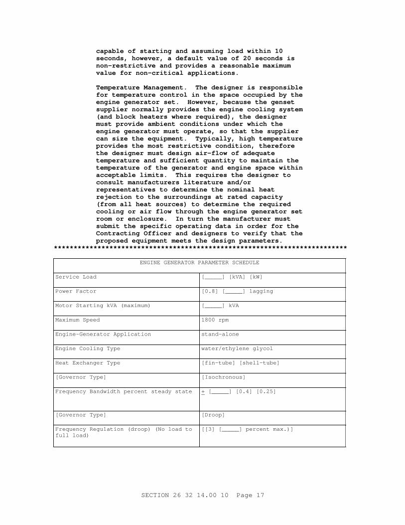
capabl e of st ar t i ng and assumi ng l oad wi t hi n 10 seconds, however , a def aul t val ue of 20 seconds i s non- r est r i c t i ve and pr ovi des a r easonabl e maxi mum val ue f or non- cr i t i cal appl i cat i ons.
Temper at ur e Management . The desi gner i s r esponsi bl e f or t emper at ur e cont r ol i n t he space occupi ed by t he engi ne gener at or set . However , because t he genset suppl i er nor mal l y pr ovi des t he engi ne cool i ng syst em ( and bl ock heat er s wher e r equi r ed) , t he desi gner must pr ovi de ambi ent condi t i ons under whi ch t he engi ne gener at or must oper at e, so t hat t he suppl i er can s i ze t he equi pment . Typi cal l y , hi gh t emper at ur e pr ovi des t he most r est r i c t i ve condi t i on, t her ef or e t he desi gner must desi gn ai r - f l ow of adequat e t emper at ur e and suf f i c i ent quant i t y t o mai nt ai n t he t emper at ur e of t he gener at or and engi ne space wi t hi n accept abl e l i mi t s. Thi s r equi r es t he desi gner t o consul t manuf act ur er s l i t er at ur e and/ or r epr esent at i ves t o det er mi ne t he nomi nal heat r ej ect i on t o t he sur r oundi ngs at r at ed capaci t y ( f r om al l heat sour ces) t o det er mi ne t he r equi r ed cool i ng or ai r f l ow t hr ough t he engi ne gener at or set r oom or encl osur e. I n t ur n t he manuf act ur er must submi t t he speci f i c oper at i ng dat a i n or der f or t he Cont r act i ng Of f i cer and desi gner s t o ver i f y t hat t he pr oposed equi pment meet s t he desi gn par amet er s.
Engi ne Cool i ng Type wat er / et hyl ene gl ycol
Heat Exchanger Type [ f i n- t ube] [ shel l - t ube]
[ Gover nor Type] [Isochronous]
Fr equency Bandwi dt h per cent st eady st at e + [ _____] [ 0. 4] [ 0. 25]
[ Gover nor Type] [Droop]
Fr equency Regul at i on ( dr oop) ( No l oad t o f ul l l oad)
[ [ 3] [ _____] per cent max. ) ]
SECTI ON 26 32 14. 00 10 Page 17
ENGI NE GENERATOR PARAMETER SCHEDULE
Fr equency Bandwi dt h per cent ( st eady st at e) + [ _____] [ 0. 4] [ 0. 25]
Vol t age Regul at i on ( No l oad t o f ul l l oad) + 2 per cent ( max. )
Vol t age Bandwi dt h ( st eady st at e) + [ 0. 5] [ 1] [ 2] per cent
Frequency [ 50] [ 60] Hz
Voltage [ _____] vol t s
Phases [ 3 Phase, Wye] [ 3 Phase, Del t a] [ 1 Phase]
Mi ni mum Gener at or React ance [ _____] per cent Subt r ansi ent
Nonl i near Loads [ _____] kVA
Max St ep Load I ncr ease [ _____] [ 100] per cent of Ser vi ce Load at [ _____] PF
Max St ep Load Decr ease ( w/ o shut down) [ _____] [ 100] per cent of Ser vi ce Load at [ _____] PF
Max Ti me t o St ar t and be Ready t o Assume Load
[ 10] [ _____] seconds
Max Summer I ndoor Temp ( Pr i or t o Genset Operation)
[ _____] degr ees CF
Mi n Wi nt er I ndoor Temp ( Pr i or t o Genset Operation)
[ _____] degr ees CF
Mi n Wi nt er I ndoor Temp [ _____] degr ees CF
Max Al l owabl e Heat Tr ansf er r ed To Engi ne Gener at or Space at Rat ed Out put Capaci t y
[ _____] kWMBTUH/ hr
Max Summer Out door Temp ( Ambi ent ) [ _____] degr ees CF
Mi n Wi nt er Out door Temp ( Ambi ent ) [ _____] degr ees CF
I nst al l at i on El evat i on [ _____] above sea l evel
1. 2. 2 Out put Capaci t y
**************************************************************************NOTE: The ser vi ce l oad f or each genset shoul d be shown on t he Engi ne- Gener at or Par amet er Schedul e. The desi gner has cont r ol over t he ser vi ce l oad. The Cont r act or t hr ough t he suppl i er ' s manuf act ur er / assembl er has cont r ol of t he ef f i c i ency and associ at ed anci l l ar y equi pment l oads.
Pr ovi de each gener at or set wi t h power equal t o t he sum of ser vi ce l oad pl us t he machi ne' s ef f i c i ency l oss and associ at ed anci l l ar y equi pment l oads. Rat ed out put capaci t y shal l al so consi der engi ne and/ or gener at or over si z i ng r equi r ed t o meet r equi r ement s i n par agr aph Engi ne- Gener at or Par amet er Schedul e.
1. 2. 3 Power Rat i ng
St andby r at i ngs shal l be i n accor dance wi t h EGSA 101P.
1. 2. 4 Engi ne Gener at or Set Encl osur e
**************************************************************************NOTE: I f t he engi ne- gener at or set i s t o be i nst al l ed out - of - door s, i ncl ude r equi r ement f or t he weat her pr oof encl osur e i n t he engi ne- gener at or set schedul e. Def i ne cor r osi on r esi st ance and/ or mat er i al r equi r ed f or t he envi r onment . Pr ovi de st r uct ur al l oadi ng r equi r ed f or t he geogr aphi c ar ea ( wi nd l oads, snow l oads, et c. ) . A gener at or set encl osur e may al so be needed t o mi t i gat e excessi ve noi se caused by t he engi ne gener at or set mechani cal component s. Del et e t he r ef er ence t o mechani cal noi se l i mi t at i ons i f an encl osur e i s not needed t o mi t i gat e sound emi ssi ons. I f a sound encl osur e i s not pr ovi ded, t he desi gner must pr ovi de a desi gn t o pr event excessi ve noi se ( meet OSHA r equi r ement s. Del et e t hi s par agr aph i f no engi ne- gener at or set encl osur e i s needed.
The engi ne gener at or set encl osur e shal l be cor r osi on r esi st ant , f ul l y weat her r esi st ant , cont ai n al l set component s, and pr ovi de vent i l at i on t o per mi t oper at i on at r at ed l oad under secur ed condi t i ons. Pr ovi de door s f or access t o al l cont r ol s and equi pment r equi r i ng per i odi c mai nt enance or adj ust ment . Pr ovi de r emovabl e panel s f or access t o component s r equi r i ng per i odi c r epl acement . The encl osur e shal l be capabl e of bei ng r emoved wi t hout di sassembl y of t he engi ne- gener at or set or r emoval of component s ot her t han exhaust syst em. The encl osur e shal l r educe t he noi se of t he gener at or set t o wi t hi n t he l i mi t s speci f i ed i n t he par agr aph SOUND LIMITATIONS.
1. 2. 5 Vi br at i on I sol at i on
**************************************************************************NOTE: See UFC 3- 450- 02, Power Pl ant Acoust i cs, and UFC 3- 450- 01, Noi se and Vi br at i on Cont r ol For Mechani cal Equi pment f or v i br at i on cr i t er i a. Choose bet ween a v i br at i on- i sol at i on syst em and t he manuf act ur er ' s st andar d mount i ng. Vi br at i on i sol at i on syst ems shoul d be appl i ed wher e v i br at i on t r ansmi t t ed t hr ough t he gener at or set suppor t st r uct ur e pr oduces ( ei t her di r ect l y or by r esonant f r equenci es of s t r uct ur al member s) annoyi ng or damagi ng v i br at i on i n t he sur r oundi ng envi r onment . Sel ect t he manuf act ur er ' s st andar d or pr ovi de t he maxi mum al l owabl e v i br at i on f or ce necessar y t o l i mi t
SECTI ON 26 32 14. 00 10 Page 19
t he maxi mum vi br at i on. Del et e t he v i br at i on i sol at i on r equi r ement f or appl i cat i ons wher e v i br at i on does not af f ect t he f l oor or f oundat i on.
The maxi mum engi ne- gener at or set v i br at i on i n t he hor i zont al , ver t i cal and axi al di r ect i ons shal l be l i mi t ed t o 0. 15 mm 6 mi l s ( peak- peak RMS) , wi t h an over al l vel oci t y l i mi t of 24 mm/ seconds 0. 95 i nches/ seconds RMS, f or al l speeds t hr ough 110 per cent of r at ed speed. [ I nst al l a v i br at i on- i sol at i on syst em bet ween t he f l oor and t he base t o l i mi t t he maxi mum vi br at i on t r ansmi t t ed t o t he f l oor at al l f r equenci es t o a maxi mum of [ _____] ( peak f or ce) . ] [ The engi ne- gener at or set shal l be pr ovi ded wi t h v i br at i on- i sol at i on i n accor dance wi t h t he manuf act ur er ' s st andar d r ecommendat i on. ] Wher e t he v i br at i on- i sol at i on syst em does not secur e t he base t o t he st r uct ur e f l oor or uni t f oundat i on, pr ovi de sei smi c r est r ai nt s i n accor dance wi t h t he sei smi c par amet er s speci f i ed.
1. 2. 5. 2 Tor si onal Anal ys i s
Submi t t or s i onal anal ysi s i ncl udi ng pr ot ot ype t est i ng or cal cul at i ons whi ch cer t i f y and demonst r at e t hat no damagi ng or danger ous t or s i onal v i br at i ons wi l l occur when t he pr i me mover i s connect ed t o t he gener at or , at synchr onous speeds, pl us/ mi nus 10 per cent .
1. 2. 5. 3 Per f or mance Dat a
Submi t v i br at i on i sol at i on syst em per f or mance dat a f or t he r ange of f r equenci es gener at ed by t he engi ne- gener at or set dur i ng oper at i on f r om no l oad t o f ul l l oad and t he maxi mum vi br at i on t r ansmi t t ed t o t he f l oor . Al so submi t a descr i pt i on of sei smi c qual i f i cat i on of t he engi ne- gener at or mount i ng, base, and vi br at i on i sol at i on.
1. 2. 6 Rel i abi l i t y and Dur abi l i t y
Submi t document at i on whi ch c i t es engi nes and gener at or s i n s i mi l ar ser vi ce t o demonst r at e compl i ance wi t h t he r equi r ement s of t hi s speci f i cat i on. Cer t i f i cat i on does not excl ude annual t echnol ogi cal i mpr ovement s made by a manuf act ur er i n t he basi c st andar d model set on whi ch exper i ence was obt ai ned, pr ovi ded par t s i nt er changeabi l i t y has not been subst ant i al l y af f ect ed and t he cur r ent st andar d model meet s al l t he per f or mance r equi r ement s of t hi s speci f i cat i on. For each di f f er ent set , 2 l i ke set s shal l have per f or med sat i sf act or i l y i n a st at i onar y power appl i cat i on, i ndependent and separ at e f r om t he physi cal l ocat i on of t he manuf act ur er ' s and assembl er ' s f aci l i t i es, f or a mi ni mum of 2 consecut i ve year s wi t hout any f ai l ur e t o st ar t , i ncl udi ng per i odi c exer ci se. The cer t i f i cat i on shal l s t at e t hat f or t he set pr oposed t o meet t hi s speci f i cat i on, t her e wer e no f ai l ur es r esul t i ng i n downt i me f or r epai r s i n excess of 72 hour s or any f ai l ur e due t o over heat i ng dur i ng 2 consecut i ve year s of ser vi ce. Li ke set s ar e of t he same model , speed, bor e, st r oke, number and conf i gur at i on of cyl i nder s, and out put power r at i ng. Li ke gener at or s ar e of t he same model , speed, pi t ch, cool i ng, exci t er , vol t age r egul at or and out put power r at i ng. A l i s t shal l be pr ovi ded wi t h t he name of t he i nst al l at i ons, compl et i on dat es, and name and t el ephone number of a poi nt of cont act .
NOTE: Revi ew submi t t al descr i pt i on ( SD) def i ni t i ons i n Sect i on 01 33 00 SUBMI TTAL PROCEDURES and edi t t he f ol l owi ng l i s t t o r ef l ect onl y t he submi t t al s r equi r ed f or t he pr oj ect .
The Gui de Speci f i cat i on t echni cal edi t or s have desi gnat ed t hose i t ems t hat r equi r e Gover nment appr oval , due t o t hei r compl exi t y or cr i t i cal i t y , wi t h a " G. " Gener al l y, ot her submi t t al i t ems can be r evi ewed by t he Cont r act or ' s Qual i t y Cont r ol Syst em. Onl y add a “ G” t o an i t em, i f t he submi t t al i s suf f i c i ent l y i mpor t ant or compl ex i n cont ext of t he pr oj ect .
For submi t t al s r equi r i ng Gover nment appr oval on Ar my pr oj ect s, a code of up t o t hr ee char act er s wi t hi n t he submi t t al t ags may be used f ol l owi ng t he " G" desi gnat i on t o i ndi cat e t he appr ovi ng aut hor i t y. Codes f or Ar my pr oj ect s usi ng t he Resi dent Management Syst em ( RMS) ar e: " AE" f or Ar chi t ect - Engi neer ; " DO" f or Di st r i c t Of f i ce ( Engi neer i ng Di v i s i on or ot her or gani zat i on i n t he Di st r i c t Of f i ce) ; " AO" f or Ar ea Of f i ce; " RO" f or Resi dent Of f i ce; and " PO" f or Pr oj ect Of f i ce. Codes f ol l owi ng t he " G" t ypi cal l y ar e not used f or Navy, Ai r For ce, and NASA pr oj ect s.
Use t he " S" c l assi f i cat i on onl y i n SD- 11 Cl oseout Submi t t al s. The " S" f ol l owi ng a submi t t al i t em i ndi cat es t hat t he submi t t al i s r equi r ed f or t he Sust ai nabi l i t y eNot ebook t o f ul f i l l f eder al l y mandat ed sust ai nabl e r equi r ement s i n accor dance wi t h Sect i on 01 33 29 SUSTAI NABI LI TY REPORTI NG.
Choose t he f i r st br acket ed i t em f or Navy, Ai r For ce and NASA pr oj ect s, or choose t he second br acket ed i t em f or Ar my pr oj ect s.
Gover nment appr oval i s r equi r ed f or submi t t al s wi t h a " G" desi gnat i on; submi t t al s not havi ng a " G" desi gnat i on ar e f or [ Cont r act or Qual i t y Cont r ol appr oval . ] [ i nf or mat i on onl y. When used, a desi gnat i on f ol l owi ng t he " G" desi gnat i on i dent i f i es t he of f i ce t hat wi l l r evi ew t he submi t t al f or t he Gover nment . ] Submi t t al s wi t h an " S" ar e f or i ncl usi on i n t he Sust ai nabi l i t y eNot ebook, i n conf or mance t o Sect i on 01 33 29 SUSTAI NABI LI TY REPORTI NG. Submi t t he f ol l owi ng i n accor dance wi t h Sect i on 01 33 00 SUBMI TTAL PROCEDURES:
SD- 02 Shop Dr awi ngs
Det ai l ed Dr awi ngs; G[ , [ _____] ]Accept ance; G[ , [ _____] ]
SD- 03 Pr oduct Dat a
Manuf act ur er ' s Cat al ogI nst r uct i ons; G[ , [ _____] ]ExperienceFi el d Engi neer
SECTI ON 26 32 14. 00 10 Page 21
Si t e Wel di ngGener al I nst al l at i onSi t e Vi s i t
SD- 05 Desi gn Dat a
Sound Li mi t at i ons; G[ , [ _____] ]GeneratorI nt egr al Mai n Fuel St or age TankDay TankPower Fact orHeat ExchangerTi me- Del ay on Al ar msCool i ng Syst emVi br at i on I sol at i on
SD- 06 Test Repor t s
Per f or mance Test sOnsi t e I nspect i on and Test s; G[ , [ _____] ]
SD- 07 Cer t i f i cat es
Vi br at i on I sol at i onPr ot ot ype Test sRel i abi l i t y and Dur abi l i t yEmissionsSound l i mi t at i onsCur r ent Bal anceMat er i al s and Equi pmentFact or y I nspect i on and Test sInspectionsCool i ng Syst em
SD- 10 Oper at i on and Mai nt enance Dat a
Oper at i on Manual ; G[ , [ _____] ]Mai nt enance Manual ; G[ , [ _____] ]Ext r a Mat er i al s
1. 4 QUALI TY ASSURANCE
1. 4. 1 Conf or mance t o Codes and St andar ds
Wher e equi pment i s speci f i ed t o conf or m t o r equi r ement s of any code or st andar d such as UL, t he desi gn, f abr i cat i on and i nst al l at i on shal l conf or m t o t he code.
1. 4. 2 Si t e Wel di ng
Wel d st r uct ur al member s i n accor dance wi t h Sect i on 05 05 23. 16 STRUCTURAL WELDI NG. For al l ot her wel di ng, qual i f y pr ocedur es and wel der s i n accor dance wi t h ASME BPVC SEC I X.
a. Wel di ng pr ocedur es qual i f i ed by ot her s, and wel der s and wel di ng oper at or s qual i f i ed by a pr evi ousl y qual i f i ed empl oyer may be accept ed as per mi t t ed by ASME B31. 1.
b. Wel der qual i f i cat i on t est s shal l be per f or med f or each wel der whose
SECTI ON 26 32 14. 00 10 Page 22
qual i f i cat i ons ar e not i n compl i ance wi t h t he r ef er enced st andar ds. Not i f y t he Cont r act i ng Of f i cer 24 hour s i n advance of qual i f i cat i on t est s. The qual i f i cat i on t est s shal l be per f or med at t he wor k s i t e i f practical.
c. The wel der or wel di ng oper at or shal l appl y t he assi gned per sonal symbol near each wel d made as a per manent r ecor d
d. Submi t a l et t er l i s t i ng t he wel der qual i f y i ng pr ocedur es f or each wel der , compl et e wi t h suppor t i ng dat a such as t est pr ocedur es used, what was t est ed t o, and a l i s t of t he names of al l wel der s and t hei r qual i f i cat i ons symbol s.
1. 4. 3 Experience
Each component manuf act ur er shal l have a mi ni mum of 3 year s exper i ence i n t he manuf act ur e, assembl y and sal e of component s used wi t h st at i onar y di esel engi ne- gener at or set s f or commer ci al and i ndust r i al use. The engi ne- gener at or set manuf act ur e/ assembl er shal l have a mi ni mum of 3 year s exper i ence i n t he manuf act ur e, assembl y and sal e of st at i onar y di esel engi ne- gener at or set s f or commer ci al and i ndust r i al use. Submi t a st at ement showi ng and ver i f y i ng t hese r equi r ement s.
1. 4. 4 Fi el d Engi neer
The engi ne- gener at or set manuf act ur er or assembl er shal l f ur ni sh a qual i f i ed f i el d engi neer t o super vi se t he compl et e i nst al l at i on of t he engi ne- gener at or set , assi st i n t he per f or mance of t he onsi t e t est s, and i nst r uct per sonnel as t o t he oper at i onal and mai nt enance f eat ur es of t he equi pment . The f i el d engi neer shal l have at t ended t he engi ne- gener at or manuf act ur er ' s t r ai ni ng cour ses on i nst al l at i on and oper at i on and mai nt enance f or engi ne gener at or set s. Submi t a l et t er l i s t i ng t he qual i f i cat i ons, school s, f or mal t r ai ni ng, and exper i ence of t he f i el d engineer.
1. 4. 5 Sei smi c Requi r ement s
**************************************************************************NOTE: Pr ovi de sei smi c r equi r ement s, i f a Gover nment desi gner ( ei t her Cor ps of f i ce or A/ E) i s t he Engi neer of Recor d, and show on t he dr awi ngs. Del et e t he br acket ed phr ase i f no sei smi c det ai l s ar e pr ovi ded. Per t i nent por t i ons of UFC 3- 310- 04 and Sect i ons 13 48 00, 23 05 48. 19, and 26 05 48. 00 10, pr oper l y edi t ed, must be i ncl uded i n t he cont r act document s.
Sei smi c r equi r ement s shal l be i n accor dance wi t h UFC 3- 310- 04 and Sect i ons 13 48 00 [ SEI SMI C] BRACI NG FOR MI SCELLANEOUS EQUI PMENT, 23 05 48. 19 [ SEI SMI C] BRACI NG FOR HVAC and 26 05 48. 00 10 SEI SMI C PROTECTI ON FOR ELECTRI CAL EQUI PMENT [ as shown on t he dr awi ngs] .
1. 4. 6 Det ai l ed Dr awi ngs
Submi t det ai l ed dr awi ngs showi ng t he f ol l owi ng:
a. Base- mount ed equi pment , compl et e wi t h base and at t achment s i ncl udi ng anchor bol t t empl at e and r ecommended cl ear ances f or mai nt enance and
SECTI ON 26 32 14. 00 10 Page 23
operation.
b. St ar t i ng syst em.
c. Fuel syst em.
d. Cool i ng syst em.
e. Exhaust syst em.
f . El ect r i c wi r i ng of r el ays, br eaker s, pr ogr ammabl e cont r ol l er s, and swi t ches i ncl udi ng s i ngl e l i ne and wi r i ng di agr ams.
g. Lubr i cat i on syst em, i ncl udi ng pi pi ng, pumps, st r ai ner s, f i l t er s, [ heat exchanger s f or l ube oi l and t ur bochar ger cool i ng, ] [ el ect r i c heat er , ] cont r ol s and wi r i ng.
h. Locat i on, t ype, and descr i pt i on of v i br at i on i sol at i on devi ces.
i . The saf et y syst em, i ncl udi ng wi r i ng schemat i cs.
j . One- l i ne schemat i c and wi r i ng di agr ams of t he gener at or , exci t er , r egul at or , gover nor , and al l i nst r ument at i on.
k. Panel l ayout s.
l . Mount i ng and suppor t f or each panel and maj or pi ece of el ect r i cal equipment.
m. Engi ne- gener at or set r i ggi ng poi nt s and l i f t i ng i nst r uct i ons.
1. 5 DELI VERY, STORAGE AND HANDLI NG
Pr oper l y pr ot ect mat er i al s and equi pment i n accor dance wi t h t he manuf act ur er s r ecommended st or age pr ocedur es, bef or e, dur i ng, and af t er i nst al l at i on. Pr ot ect st or ed i t ems f r om t he weat her and cont ami nat i on. Dur i ng i nst al l at i on, pi pi ng and s i mi l ar openi ngs shal l be capped t o keep out di r t and ot her f or ei gn mat t er .
1. 6 MAI NTENANCE SERVI CE
Submi t t he oper at i on and mai nt enance manual s and have t hem appr oved pr i or t o commenci ng onsi t e t est s.
1. 6. 1 Oper at i on Manual
Pr ovi de [ t hr ee] [ _____] copi es of t he [ manuf act ur er s st andar d oper at i on manual ] [ oper at i on manual i n 216 by 279 mm 8- 1/ 2 by 11 i nch t hr ee- r i ng bi nder s] . Sect i ons shal l be separ at ed by heavy pl ast i c di v i der s wi t h t abs whi ch i dent i f y t he mat er i al i n t he sect i on. Dr awi ngs shal l be f ol ded bl ue l i nes, wi t h t he t i t l e bl ock v i s i bl e, and pl aced i n 216 by 279 mm 8- 1/ 2 by 11 i nch pl ast i c pocket s wi t h r ei nf or ced hol es. The manual shal l i ncl ude:
a. St ep- by- st ep pr ocedur es f or syst em st ar t up, oper at i on, and shut down;
b. Dr awi ngs, di agr ams, and si ngl e- l i ne schemat i cs t o i l l ust r at e and def i ne t he el ect r i cal , mechani cal , and hydr aul i c syst ems wi t h t hei r cont r ol s, al ar ms, and saf et y syst ems;
SECTI ON 26 32 14. 00 10 Page 24
c. Pr ocedur es f or i nt er f ace and i nt er act i on wi t h r el at ed syst ems t o i ncl ude [ aut omat i c t r ansf er swi t ches] [ f i r e al ar m/ suppr essi on syst ems] [ l oad sheddi ng syst ems] [ uni nt er r upt i bl e power suppl i es] [ _____] .
1. 6. 2 Mai nt enance Manual
Pr ovi de [ t hr ee] [ _____] copi es of t he [ manuf act ur er s st andar d mai nt enance manual ] [ mai nt enance manual cont ai ni ng t he i nf or mat i on descr i bed bel ow i n 216 x 279 mm 8- 1/ 2 x 11 i nch t hr ee- r i ng bi nder s] . Each sect i on shal l be separ at ed by a heavy pl ast i c di v i der wi t h t abs. Dr awi ngs shal l be f ol ded, wi t h t he t i t l e bl ock v i s i bl e, and pl aced i n pl ast i c pocket s wi t h r ei nf or ced hol es. The manual shal l i ncl ude:
a. [ Pr ocedur es f or each r out i ne mai nt enance i t em. ] [ Pr ocedur es f or t r oubl eshoot i ng. ] [ Fact or y- ser vi ce, t ake- down over haul , and r epai r ser vi ce manual s, wi t h par t s l i s t s . ]
b. The manuf act ur er ' s r ecommended mai nt enance schedul e.
c. A component l i s t whi ch i ncl udes t he manuf act ur er ' s name, addr ess, t ype or st y l e, model or ser i al number , r at i ng, and cat al og number f or t he maj or component s l i s t ed i n par agr aph GENERAL REQUI REMENTS.
d. A l i s t of spar e par t s f or each pi ece of equi pment and a compl et e l i s t of mat er i al s and suppl i es needed f or oper at i on.
1. 6. 3 Ext r a Mat er i al s
Pr ovi de t wo set s of speci al t ool s and t wo set s of f i l t er s r equi r ed f or mai nt enance. Speci al t ool s ar e t hose t hat onl y t he manuf act ur er pr ovi des, f or speci al pur poses, or t o r each ot her wi se i naccessi bl e par t s. One handset shal l be pr ovi ded f or each el ect r oni c gover nor when r equi r ed t o i ndi cat e and/ or change gover nor r esponse set t i ngs. Suppl y t wo compl et e set s of f i l t er s i n a sui t abl e st or age box i n addi t i on t o f i l t er s r epl aced af t er t est i ng.
PART 2 PRODUCTS
2. 1 NAMEPLATES
**************************************************************************NOTE: Del et e any equi pment not appl i cabl e t o t he project.
Each maj or component of t hi s speci f i cat i on shal l have t he manuf act ur er ' s name, t ype or st y l e, model or ser i al number , and r at i ng number on a pl at e secur ed t o t he equi pment . As a mi ni mum, namepl at es shal l be pr ovi ded f or : Engi nes; Rel ays; Gener at or s; Day t anks; Tr ansf or mer s ( CT & PT) ; Regul at or s; Pumps and pump mot or s; Gover nor s; Gener at or Br eaker ; Economi zer s; Heat exchanger s ( ot her t han base- mount ed) .
Wher e t he f ol l owi ng equi pment i s pr ovi ded as a st andar d component by t he di esel - engi ne gener at or set manuf act ur er , t he namepl at e i nf or mat i on may be pr ovi ded i n t he mai nt enance manual i n l i eu of namepl at es.
Bat t er y char ger Heat er sExhaust muf f l er s Exci t er sSwi t chgear Si l encer s
SECTI ON 26 32 14. 00 10 Page 25
Battery
2. 2 SAFETY DEVI CES
Exposed movi ng par t s, par t s t hat pr oduce hi gh oper at i ng t emper at ur es, par t s whi ch may be el ect r i cal l y ener gi zed, and par t s t hat may be a hazar d t o oper at i ng per sonnel dur i ng nor mal oper at i on shal l be i nsul at ed, f ul l y encl osed, guar ded, or f i t t ed wi t h ot her t ypes of saf et y devi ces. The saf et y devi ces shal l be i nst al l ed so t hat pr oper oper at i on of t he equi pment i s not i mpai r ed.
2. 3 MATERI ALS AND EQUI PMENT
Mat er i al s and equi pment shal l be as speci f i ed. Submi t a l et t er cer t i f y i ng t hat wher e mat er i al s or equi pment ar e speci f i ed t o compl y wi t h r equi r ement s of UL, or ot her st andar ds, wr i t t en pr oof of such compl i ance has been obt ai ned. The l abel or l i s t i ng of t he speci f i ed agency, or a wr i t t en cer t i f i cat e f r om an appr oved, nat i onal l y r ecogni zed t est i ng or gani zat i on equi pped t o per f or m such ser vi ces, st at i ng t hat t he i t ems have been t est ed and conf or m t o t he r equi r ement s and t est i ng met hods of t he speci f i ed agency ar e accept abl e as pr oof .
2. 3. 1 Ci r cui t Br eaker s, Low Vol t age
UL 489 and UL 489.
2. 3. 2 Fi l t er El ement s ( Fuel - oi l , Lubr i cat i ng- oi l , and Combust i on- ai r )
Manuf act ur er ' s st andar d.
2. 3. 3 I nst r ument Tr ansf or mer s
NEMA/ ANSI C12. 11.
2. 3. 4 Pi pe ( Fuel / Lube- oi l , Compr essed- Ai r , Cool ant and Exhaust )
ASTM A53/ A53M, ASTM A106/ A106M or ASTM A135/ A135M, st eel pi pe. Pi pe smal l er t han 50 mm 2 i nches shal l be Schedul e 80. Pi pe 50 mm 2 i nches and l ar ger shal l be Schedul e 40.
2. 3. 5 Pi pe Fl anges and Fi t t i ngs
2. 3. 5. 1 Pi pe Fl anges and Fl anged Fi t t i ngs
ASTM A181/ A181M, Cl ass 60, or ASME B16. 5, Gr ade 1, Cl ass 150.
2. 3. 5. 2 Pi pe Wel di ng Fi t t i ngs
ASTM A234/ A234M, Gr ade WPB or WPC, Cl ass 150, or ASME B16. 11, 1360. 7 kg 3000 l b.
2. 3. 5. 3 Thr eaded Fi t t i ngs
ASME B16. 3, Cl ass 150.
2. 3. 5. 4 Valves
MSS SP- 80, Cl ass 150.
SECTI ON 26 32 14. 00 10 Page 26
2. 3. 5. 5 Gaskets
Manuf act ur er s St andar d.
2. 3. 6 Pi pe Hanger s
MSS SP- 58.
2. 3. 7 El ect r i cal Encl osur es
2. 3. 7. 1 General
NEMA I CS 6.
2. 3. 7. 2 Panelboards
NEMA PB 1.
2. 3. 8 El ect r i c Mot or s
El ect r i c mot or s shal l conf or m t o t he r equi r ement s of NEMA MG 1. Mot or s shal l have seal ed bal l bear i ngs, a maxi mum speed of 1800 r pm and i nt egr al aut omat i c or manual r eset t her mal over l oad pr ot ect or s. Mot or s used i ndoor s shal l have dr i p pr oof f r ames; t hose used out s i de shal l be t ot al l y encl osed. AC mot or s l ar ger t han 373 W 1/ 2 Hp shal l be of t he squi r r el cage i nduct i on t ype f or st andar d vol t age of [ [ 200] [ 230] [ 460] [ 560] vol t s, 60 Hz] [ [ 240] [ 380] vol t s, 50 Hz] t hr ee phase power . AC mot or s 373 W 1/ 2 Hp or smal l er , shal l be f or st andar d vol t age [ [ 115] [ 230] vol t s, 60 Hz, ] [ [ 110] [ 220] [ 240] vol t s, 50 Hz, ] s i ngl e phase power .
2. 3. 9 Mot or Cont r ol l er s
Mot or cont r ol l er s and st ar t er s shal l conf or m t o t he r equi r ement s of NFPA 70 and NEMA I CS 2.
2. 4 ENGINE
**************************************************************************NOTE: Speci f y f uel t ype i f di f f er ent f r om No. 2 diesel.
Each engi ne shal l oper at e on No. 2- D di esel conf or mi ng t o ASTM D975, shal l be desi gned f or st at i onar y appl i cat i ons and shal l be compl et e wi t h anci l l ar i es. The engi ne shal l be a st andar d pr oduct i on model descr i bed i n t he manuf act ur er ' s cat al og dat a, whi ch descr i bes and depi ct s each engi ne- gener at or set and al l anci l l ar y equi pment i n suf f i c i ent det ai l t o demonst r at e speci f i cat i on compl i ance. The engi ne shal l be nat ur al l y aspi r at ed, scavenged, super char ged or t ur bochar ged. The engi ne shal l be t wo- or f our - st r oke- cycl e and compr essi on- i gni t i on t ype. The engi ne shal l be ver t i cal i nl i ne, V- , or opposed- pi st on t ype, wi t h a sol i d cast bl ock or i ndi v i dual l y cast cyl i nder s. The engi ne shal l have a mi ni mum of t wo cyl i nder s. Opposed- pi st on t ype engi nes shal l have no l ess t han f our cyl i nder s. Each bl ock shal l have a cool ant dr ai n por t . Each engi ne shal l be equi pped wi t h an over speed sensor .
2. 5 FUEL SYSTEM
The f uel syst em f or each engi ne gener at or set shal l conf or m t o t he
SECTI ON 26 32 14. 00 10 Page 27
r equi r ement s of NFPA 30 and NFPA 37 and cont ai n t he f ol l owi ng el ement s.
2. 5. 1 Pumps
2. 5. 1. 1 Mai n Pump
Each engi ne shal l be pr ovi ded wi t h an engi ne dr i ven pump. The pump shal l suppl y f uel at a mi ni mum r at e suf f i c i ent t o pr ovi de t he amount of f uel r equi r ed t o meet t he per f or mance i ndi cat ed wi t hi n t he par amet er schedul e. The f uel f l ow r at e shal l be based on meet i ng t he l oad r equi r ement s and al l necessar y r eci r cul at i on.
2. 5. 1. 2 Auxi l i ar y Fuel Pump
**************************************************************************NOTE: The auxi l i ar y f uel pump i s r equi r ed t o suppor t t he mai n pump i f t he l engt h of pi pe f r om t he day t ank t o t he mai n pump i s gr eat er t han t he val ue r ecommended by t he engi ne manuf act ur er . Thi s val ue may be appr oxi mat el y 12m 40 f eet ; however , engi ne manuf act ur er s shoul d be consul t ed dur i ng desi gn t o ver i f y t he pumpi ng r equi r ement s.
Auxi l i ar y f uel pumps shal l be pr ovi ded t o mai nt ai n t he r equi r ed engi ne f uel pr essur e, ei t her r equi r ed by t he i nst al l at i on or i ndi cat ed on t he dr awi ngs. The auxi l i ar y pump shal l be dr i ven by a dc el ect r i c mot or power ed by t he st ar t i ng/ st at i on bat t er i es. The auxi l i ar y pump shal l be aut omat i cal l y act uat ed by a pr essur e det ect i ng devi ce.
2. 5. 2 Filter
A mi ni mum of one f ul l f l ow f uel f i l t er shal l be pr ovi ded f or each engi ne. The f i l t er shal l be r eadi l y accessi bl e and capabl e of bei ng changed wi t hout di sconnect i ng t he pi pi ng or di st ur bi ng ot her component s. The f i l t er shal l have i nl et and out l et connect i ons pl ai nl y mar ked.
2. 5. 3 Rel i ef / Bypass Val ve
A r el i ef / bypass val ve shal l be pr ovi ded t o r egul at e pr essur e i n t he f uel suppl y l i ne, r et ur n excess f uel t o a r et ur n l i ne, and pr event t he bui l d- up of excessi ve pr essur e i n t he f uel syst em.
2. 5. 4 I nt egr al Mai n Fuel St or age Tank
**************************************************************************NOTE: Del et e t hi s par agr aph i f an i nt egr al mai n f uel st or age t ank i s not desi r ed.
An i nt egr al mai n f uel st or age t ank wi l l be t he onl y f uel sour ce f or t he engi ne. These t anks may be usef ul f or appl i cat i ons t hat r equi r e a mi ni mal f uel st or age capaci t y .
Due t o t he mi ni mal st or age capaci t y, i nt egr al mai n f uel st or age t anks ar e not pr act i cal f or pr i me power usage. They ar e al so not pr act i cal f or st andby uni t s t hat r equi r e l ar ge f uel quant i t i es. The desi gner shoul d consi der t he avai l abi l i t y and ant i c i pat ed
SECTI ON 26 32 14. 00 10 Page 28
f r equency of f uel t r uck del i ver i es when deci di ng whet her or not t o use an i nt egr al mai n f uel st or age t ank. These t anks shoul d al so not be used i n l ocat i ons wher e a t r uck f uel i ng hose can not r each t he di esel gener at or set .
See NFPA 99 and NFPA 110 f or gui dance on f uel t ank sizes.
See NFPA 37 r est r i c t i ons on al l owabl e t ank s i zes and encl osur es. I nt egr al t anks al l ow f or 1 t o 8 hour s of oper at i on dependi ng on di esel gener at or s i ze and conf i gur at i on. Consul t gener at or set manuf act ur er f or t he pr oper hour s of oper at i on f or t he appl i cat i on of i nt egr al t anks. St andby appl i cat i ons f or use wi t h f i r e pumps wi l l have t anks s i zed f or 8 hour s dur at i on. The t ank can be s i zed by t he desi gner or t he Cont r act or . The si ze of t he t ank shoul d be based on a f uel f l ow r at e t hat i s equal t o t he val ue of a t ypi cal engi ne manuf act ur er f or t he i ndi cat ed engi ne gener at or s i ze. A val ue of 200 per cent of t he expect ed f uel consumpt i on of t he engi ne i s not unusual f or t he f l ow r at e of t he mai n f uel pump. Si nce t he excess f uel wi l l be r et ur ned t o t he t ank, t he desi gner shoul d consi der t he i mpact of heat bui l dup when si z i ng t he t ank. I f a f uel oi l cool er i s not used, t he day t ank s i ze may need t o be i ncr eased t o pr oper l y di ssi pat e t he heat absor bed by t he f uel .
Each engi ne shal l be pr ovi ded wi t h an i nt egr al mai n f uel t ank. Each t ank shal l be f act or y i nst al l ed and pr ovi ded as an i nt egr al par t of t he di esel gener at or manuf act ur er ' s pr oduct . Each t ank shal l be pr ovi ded wi t h connect i ons f or f uel suppl y l i ne, f uel r et ur n l i ne, l ocal f uel f i l l por t , gauge, vent l i ne, and f l oat swi t ch assembl y. A f uel r et ur n l i ne cool er shal l be pr ovi ded as r ecommended by t he manuf act ur er and assembl er . The t emper at ur e of t he f uel r et ur ni ng t o t he t ank shal l be bel ow t he f l ash poi nt of t he f uel . Each engi ne- gener at or set pr ovi ded wi t h weat her pr oof encl osur es shal l have i t s t ank mount ed wi t hi n t he encl osur e. The f uel f i l l l i ne shal l be accessi bl e wi t hout openi ng t he encl osur e.
2. 5. 4. 1 Capacity
Each t ank shal l have capaci t y [ as i ndi cat ed] [ t o suppl y f uel t o t he engi ne f or an uni nt er r upt ed [ 4- hour ] [ _____] per i od] at 100 per cent r at ed l oad wi t hout bei ng r ef i l l ed.
2. 5. 4. 2 Local Fuel Fi l l
Each l ocal f uel f i l l por t on t he day t ank shal l be pr ovi ded wi t h a scr ew- on cap.
2. 5. 4. 3 Fuel Level Cont r ol s
Each t ank shal l have a f l oat - swi t ch assembl y t o per f or m t he f ol l owi ng functions:
a. Act i vat e t he " Low Fuel Level " al ar m at 70 per cent of t he r at ed t ank
SECTI ON 26 32 14. 00 10 Page 29
capacity.
b. Act i vat e t he " Over f i l l Fuel Level " al ar m at 95 per cent of t he r at ed t ank capaci t y.
2. 5. 4. 4 Arrangement
I nt egr al t anks may al l ow gr avi t y f l ow i nt o t he engi ne. Gr avi t y f l ow t anks and any t ank t hat al l ows a f uel l evel above t he f uel i nj ect or s shal l be pr ovi ded wi t h an i nt er nal or ext er nal f act or y i nst al l ed val ve l ocat ed as near as possi bl e t o t he shel l of t he t ank. The val ve shal l c l ose when t he engi ne i s not oper at i ng. I nt egr al day t anks shal l be pr ovi ded wi t h any necessar y pumps t o suppl y f uel t o t he engi ne as r ecommended by t he gener at or set manuf act ur er . The f uel suppl y l i ne f r om t he t ank t o t he manuf act ur er ' s st andar d engi ne connect i on shal l be wel ded pi pe.
2. 5. 5 Day Tank
**************************************************************************NOTE: Del et e t hi s par agr aph i f an i nt egr al mai n f uel st or age t ank i s used.
See NFPA 37 r est r i c t i ons on al l owabl e day t ank s i zes and encl osur es. Sel ect ei t her sel f - suppor t i ng or i nt egr al day t ank. Sel ect t he f i r st opt i on bel ow f or appl i cat i ons wher e f uel i s r et ur ned t o t he day t ank. Sel ect t he second opt i on bel ow f or appl i cat i ons wher e f uel i s r et ur ned t o t he mai n t ank. I nt egr al day t anks al l ow f or 1 t o 8 hour s of oper at i on. Consul t gener at or set manuf act ur er f or t he pr oper hour s of oper at i on f or t he appl i cat i on of i nt egr al day t anks. St andby appl i cat i ons f or use wi t h f i r e pumps wi l l have day t anks s i zed f or 8 hour s dur at i on. Sel ect day t ank capaci t y f or ei t her pr i me or st andby appl i cat i on. The day t ank can be s i zed by t he desi gner or t he Cont r act or . The si ze of t he day t ank shoul d be based on a f uel f l ow r at e t hat i s equal t o t he val ue of a t ypi cal engi ne manuf act ur er f or t he i ndi cat ed engi ne gener at or s i ze. A val ue of 200 per cent of t he expect ed f uel consumpt i on of t he engi ne i s not unusual f or t he f l ow r at e of t he mai n f uel pump. The excess f uel may be r et ur ned t o t he day t ank or mai n f uel t ank. The desi gner shoul d al so consi der t he i mpact of heat bui l d up when si z i ng t he day t ank. I f a f uel oi l cool er i s not used or i f f uel i s r et ur ned t o t he day t ank, t he day t ank s i ze may need t o be i ncr eased t o pr oper l y di ssi pat e t he heat absor bed by t he f uel .
Pr ovi de each engi ne wi t h [ a separ at e sel f - suppor t i ng] [ i nt egr al ] day t ank. [ Pr ovi de each day t ank wi t h connect i ons f or f uel suppl y l i ne, f uel r et ur n l i ne, f uel over f l ow l i ne, l ocal f uel f i l l por t , gauge, vent l i ne, dr ai n l i ne, and f l oat swi t ch assembl y f or cont r ol . Pr ovi de a f uel r et ur n l i ne cool er as r ecommended by t he manuf act ur er and assembl er . The t emper at ur e of t he f uel r et ur ni ng t o t he day t ank shal l be bel ow t he f l ash poi nt of t he f uel . I nst al l a t emper at ur e sensi ng devi ce i n t he f uel suppl y l i ne. ] [ Pr ovi de each day t ank wi t h connect i ons f or f uel suppl y l i ne, f uel over f l ow l i ne, l ocal f uel f i l l por t , gauge, vent l i ne, dr ai n l i ne, and f l oat swi t ch
SECTI ON 26 32 14. 00 10 Page 30
assembl y f or cont r ol . ] Each engi ne- gener at or set pr ovi ded wi t h weat her pr oof encl osur es shal l have i t s day t ank mount ed wi t hi n t he encl osur e. The f uel f i l l l i ne shal l be accessi bl e wi t hout openi ng t he enclosure.
2. 5. 5. 1 Capaci t y, St andby
Each day t ank shal l have capaci t y [ as i ndi cat ed] [ t o suppl y f uel t o t he engi ne f or an uni nt er r upt ed [ 4- hour ] [ _____] per i od at 100 per cent r at ed l oad wi t hout bei ng r ef i l l ed, pl us any f uel whi ch may be r et ur ned t o t he mai n f uel st or age t ank. Submi t cal cul at i ons f or t he capaci t y of each day t ank, i ncl udi ng al l owances f or r eci r cul at ed f uel , usabl e t ank capaci t y, and dur at i on of f uel suppl y. The cal cul at i on of t he capaci t y of each day t ank shal l i ncor por at e t he r equi r ement t o st op t he suppl y of f uel i nt o t he day t ank at 90 per cent of t he ul t i mat e vol ume of t he t ank. ]
2. 5. 5. 2 Dr ai n Li ne
Each day t ank dr ai n l i ne shal l be accessi bl e and equi pped wi t h a shut of f val ve. Sel f suppor t i ng day t anks shal l be ar r anged t o al l ow dr ai nage i nt o a 305 mm 12 i nch t al l bucket .
2. 5. 5. 3 Local Fuel Fi l l
Pr ovi de each l ocal f uel f i l l por t on t he day t ank wi t h a scr ew- on cap.
2. 5. 5. 4 Fuel Level Cont r ol s
Each day t ank shal l have a f l oat - swi t ch- assembl y t o per f or m t he f ol l owi ng functions:
a. [ When t he mai n st or age t ank i s l ocat ed hi gher t han t he day t ank, open t he sol enoi d val ve l ocat ed on t he f uel suppl y l i ne ent er i ng t he day t ank and st ar t t he suppl y of f uel i nt o t he day t ank] [ St ar t t he suppl y of f uel i nt o t he day t ank] when t he f uel l evel i s at t he " Low" l evel mar k, 75 of t he r at ed t ank capaci t y.
b. [ When t he mai n st or age t ank i s l ocat ed hi gher t han t he day t ank, st op t he suppl y of f uel i nt o t he day t ank and cl ose t he sol enoi d val ve l ocat ed on t he f uel suppl y l i ne ent er i ng t he day t ank] [ St op t he suppl y of f uel i nt o t he day t ank] when t he f uel l evel i s at 90 per cent of t he r at ed t ank capaci t y.
c. Act i vat e t he " Over f i l l Fuel Level " al ar m at 95 per cent of t he r at ed t ank vol ume.
d. Act i vat e t he " Low Fuel Level " al ar m at 70 per cent of t he r at ed t ank Capacity.
e. Act i vat e t he aut omat i c f uel suppl y shut - of f val ve l ocat ed on t he f i l l l i ne of t he day t ank and shut down t he f uel pump whi ch suppl i es f uel t o t he day t ank at 95 per cent of t he r at ed t ank vol ume. The f l ow of f uel shal l be st opped bef or e any f uel can be f or ced i nt o t he f uel over f l ow l i ne.
2. 5. 5. 5 Arrangement
**************************************************************************NOTE: Sel ect bet ween i nt egr al and sel f suppor t i ng
SECTI ON 26 32 14. 00 10 Page 31
day t anks. Al so, sel ect bet ween appl i cat i ons wher e t he mai n f uel st or age t ank i s l ocat ed above t he day t ank and appl i cat i ons wher e t he mai n f uel st or age t ank i s l ocat ed bel ow t he day t ank. The l ocat i on of al l t anks, pi pi ng, and val ves shoul d al so be i ndi cat ed on t he dr awi ngs.
[ I nt egr al day t anks may al l ow gr avi t y f l ow i nt o t he engi ne. Gr avi t y f l ow t anks shal l be pr ovi ded wi t h an i nt er nal or ext er nal val ve l ocat ed as near as possi bl e t o t he shel l of t he t ank. The val ve shal l c l ose when t he engi ne i s not oper at i ng. I nt egr al day t anks shal l be pr ovi ded wi t h any necessar y pumps t o suppl y f uel t o t he engi ne as r ecommended by t he gener at or set manuf act ur er . The over f l ow connect i on and t he f uel suppl y l i ne f or i nt egr al day t anks whi ch do not r el y upon gr avi t y f l ow shal l be ar r anged so t hat t he hi ghest possi bl e f uel l evel i s bel ow t he f uel i nj ect or s. ] [ Sel f - suppor t i ng day t ank shal l ei t her be ar r anged so t hat t he f uel l evel i n t he day t ank r emai ns above t he suct i on por t of t he engi ne dr i ven f uel pump or be pr ovi ded wi t h a t r ansf er pump t o pr ovi de f uel t o t he engi ne dr i ven pump. The over f l ow connect i on and f uel suppl y l i ne shal l be ar r anged so t hat t he hi ghest possi bl e f uel l evel i s bel ow t he f uel i nj ect or s. ] [ When t he mai n f uel st or age t anks ar e l ocat ed bel ow t he day t ank, a check val ve shal l be pr ovi ded i n t he f uel suppl y l i ne ent er i ng t he day t ank. ] [ When t he mai n f uel s t or age t anks ar e l ocat ed above t he day t ank, a sol enoi d val ve shal l be i nst al l ed i n t he f uel suppl y l i ne ent er i ng t he day t ank. The sol enoi d val ve shal l be i n addi t i on t o t he aut omat i c f uel shut of f val ve. ] The f uel suppl y l i ne f r om t he day t ank t o t he manuf act ur er ' s st andar d engi ne connect i on shal l be wel ded pi pe.
2. 5. 6 Fuel Suppl y Syst em
**************************************************************************NOTE: Del et e t hi s par agr aph i f an i nt egr al mai n f uel st or age t ank i s used.
The f uel suppl y f r om t he mai n st or age of f uel t o t he day t ank shal l be as speci f i ed i n Sect i on 33 56 10 FACTORY- FABRI CATED FUEL STORAGE TANKS.
2. 6 LUBRICATION
Each engi ne shal l have a separ at e l ube- oi l syst em conf or mi ng t o NFPA 30 and NFPA 37. Each syst em shal l be pr essur i zed by engi ne- dr i ven oi l pumps. Each syst em shal l be f ur ni shed wi t h a r el i ef val ve f or oi l pr essur e r egul at i on ( f or c l osed syst ems) and a di p- st i ck f or oi l l evel i ndi cat i ons. The cr ankcase shal l be vent ed i n accor dance wi t h t he manuf act ur er ' s r ecommendat i on except t hat i t shal l not be vent ed t o t he engi ne exhaust syst em. Cr ankcase br eat her s, i f pr ovi ded on engi nes i nst al l ed i n bui l di ngs or encl osur es, shal l be pi ped t o vent t o t he out s i de. The syst em shal l be r eadi l y accessi bl e f or ser vi ce such as dr ai ni ng, r ef i l l i ng, et c. Each syst em shal l per mi t addi t i on of oi l and have oi l - l evel i ndi cat i on wi t h t he set oper at i ng. The syst em shal l ut i l i ze an oi l cool er as r ecommended by t he engi ne manuf act ur er .
2. 6. 1 Filter
One f ul l - f l ow f i l t er shal l be pr ovi ded f or each pump. The f i l t er shal l be r eadi l y accessi bl e and capabl e of bei ng changed wi t hout di sconnect i ng t he pi pi ng or di st ur bi ng ot her component s. The f i l t er shal l have i nl et and
SECTI ON 26 32 14. 00 10 Page 32
out l et connect i ons pl ai nl y mar ked.
2. 6. 2 Lube- Oi l Sensor s
Each engi ne shal l be equi pped wi t h l ube- oi l pr essur e sensor s. Pr essur e sensor s shal l be l ocat ed downst r eam of t he f i l t er s and pr ovi de s i gnal s f or r equi r ed i ndi cat i on and al ar ms.
2. 7 COOLI NG SYSTEM
**************************************************************************NOTE: Coor di nat e wi t h par agr aph SYSTEM DESCRI PTI ON.
Each engi ne cool i ng syst em shal l oper at e aut omat i cal l y whi l e t he engi ne i s r unni ng. Each cool i ng syst em shal l be s i zed f or t he maxi mum summer [ out door ] [ i ndoor ] desi gn t emper at ur e and si t e el evat i on. Wat er - cool ed syst em cool ant shal l use a combi nat i on of wat er and et hyl ene- gl ycol suf f i c i ent f or f r eeze pr ot ect i on at t he mi ni mum wi nt er out door t emper at ur e speci f i ed. The maxi mum t emper at ur e r i se of t he cool ant acr oss t he engi ne shal l be no mor e t han t hat r ecommended and submi t t ed.
a. The maxi mum and mi ni mum al l owabl e i nl et t emper at ur es of t he [ cool ant f l ui d] [ cool i ng ai r ] .
b. The maxi mum al l owabl e t emper at ur e r i se i n t he [ cool ant f l ui d t hr ough t he engi ne] [ cool i ng ai r acr oss t he engi ne] .
c. The mi ni mum al l owabl e i nl et f uel t emper at ur e.
2. 7. 1 Cool ant Pumps
Cool ant pumps shal l be t he cent r i f ugal t ype. Each engi ne shal l have an engi ne- dr i ven pr i mar y pump. Secondar y pumps shal l be el ect r i c mot or dr i ven and have aut omat i c cont r ol l er s.
2. 7. 2 Heat Exchanger
Each heat exchanger shal l be of a s i ze and capaci t y t o l i mi t t he maxi mum al l owabl e t emper at ur e r i se i n t he cool ant acr oss t he engi ne t o t hat r ecommended and submi t t ed i n accor dance wi t h par agr aph SUBMI TTALS f or t he maxi mum summer out door desi gn t emper at ur e and si t e el evat i on. Each heat exchanger shal l be cor r osi on r esi st ant , sui t abl e f or ser vi ce i n ambi ent condi t i ons of appl i cat i on. Submi t manuf act ur er s dat a t o quant i f y heat r ej ect ed t o t he space wi t h t he engi ne gener at or set at r at ed capaci t y.
2. 7. 2. 1 Fi n- Tube- Type Heat Exchanger ( Radi at or )
**************************************************************************NOTE: Keep t hi s par agr aph and del et e t he next par agr aph, i f r equi r ed by t he pr oj ect .
Heat exchanger may be f act or y coat ed wi t h cor r osi ve r esi st ant f i l m pr ovi di ng t hat cor r osi on measur es ar e t aken t o r est or e t he heat r ej ect i on capabi l i t y of t he r adi at or t o t he i ni t i al desi gn r equi r ement v i a over si z i ng, or ot her compensat i ng met hods. I nt er nal sur f aces shal l be compat i bl e wi t h l i qui d f l ui d cool ant used. Mat er i al s and cool ant ar e subj ect t o appr oval by t he Cont r act i ng Of f i cer . Heat exchanger s shal l be
SECTI ON 26 32 14. 00 10 Page 33
pr essur e t ype i ncor por at i ng a pr essur e val ve, vacuum val ve and a cap. Caps shal l be desi gned f or pr essur e r el i ef pr i or t o r emoval . Each heat exchanger and t he ent i r e cool i ng syst em shal l be capabl e of wi t hst andi ng a mi ni mum pr essur e of 48 kPa gauge 7 psi . Each heat exchanger shal l be pr ot ect ed wi t h a st r ong gr i l l e or scr een guar d. Each heat exchanger shal l have at l east t wo t apped hol es. One t apped hol e i n t he heat exchanger shal l be equi pped wi t h a dr ai n cock, t he r est shal l be pl ugged.
2. 7. 2. 2 Shel l and U- Tube Type Heat Exchanger
**************************************************************************NOTE: Keep t hi s par agr aph and del et e par agr aph above, i f r equi r ed by t he pr oj ect .
Heat exchanger shal l be mul t i pl e pass shel l and U- t ube t ype. Exchanger shal l oper at e wi t h l ow t emper at ur e wat er i n t he shel l and hi gh t emper at ur e wat er i n t he t ubes. Exchanger s shal l be const r uct ed i n accor dance wi t h ASME BPVC SEC VI I I D1 and cer t i f i ed ASME st amp secur ed t o t he uni t . U- t ube bundl es shal l be compl et el y r emovabl e f or c l eani ng and t ube r epl acement and shal l be f r ee t o expand wi t h t he shel l . Shel l s shal l be const r uct ed of seaml ess st eel pi pe or wel ded st eel . Tubes shal l be cupr oni ckel or i nhi bi t ed admi r al t y, const r uct ed i n accor dance wi t h ASTM B395/ B395M, sui t abl e f or t he t emper at ur e and pr essur e speci f i ed. Tubes shal l be not l ess t han 19 mm 3/ 4 i nch unl ess ot her wi se i ndi cat ed. Shel l s i de and t ube si de shal l be desi gned f or 1. 03 kPa 150 psi wor ki ng pr essur e and f act or y t est ed at 2. 06 kPa 300 psi . Hi gh and l ow t emper at ur e wat er and pr essur e r el i ef connect i ons shal l be l ocat ed i n accor dance wi t h t he manuf act ur er s st andar d pr act i ce. Wat er connect i ons l ar ger t han 76 mm 3 i nches shal l be ASME Cl ass 150 f l anged. Wat er pr essur e l oss t hr ough cl ean t ubes shal l be as r ecommended by t he engi ne manuf act ur er . Mi ni mum wat er vel oci t y t hr ough t ubes shal l be 300 mm 1 f oot per second and assur e t ur bul ent f l ow. One or mor e pr essur e r el i ef val ves shal l be pr ovi ded f or each heat exchanger i n accor dance wi t h ASME BPVC SEC VI I I D1. The aggr egat e r el i evi ng capaci t y of t he r el i ef val ves shal l be not l ess t han t hat r equi r ed by t he above code. Di schar ge f r om t he val ves shal l be i nst al l ed as i ndi cat ed. The r el i ef val ves shal l be i nst al l ed on t he heat exchanger shel l . A dr ai n connect i on wi t h 19 mm 3/ 4 i nch hose bi b shal l be i nst al l ed at t he l owest poi nt i n t he syst em near t he heat exchanger . Addi t i onal dr ai n connect i on wi t h t hr eaded cap or pl ug shal l be i nst al l ed wher ever r equi r ed f or t hor ough dr ai ni ng of t he syst em.
2. 7. 3 Expansi on Tank
**************************************************************************NOTE: Del et e t hi s par agr aph i f a shel l and U- t ube t ype heat exchanger i s not needed.
The cool i ng syst em shal l i ncl ude an ai r expansi on t ank whi ch wi l l accommodat e t he expanded wat er of t he syst em gener at ed wi t hi n t he nor mal oper at i ng t emper at ur e r ange, l i mi t i ng t he pr essur e i ncr ease at al l component s i n t he syst em t o t he maxi mum al l owabl e pr essur e at t hose component s. The t ank shal l be sui t abl e f or an oper at i ng t emper at ur e of 121 degr ees C 250 degr ees F and a wor ki ng pr essur e of 0. 86 MPa 125 psi . The t ank shal l be const r uct ed of wel ded st eel , t est ed and st amped i n accor dance with ASME BPVC SEC VI I I D1 f or t he st at ed wor ki ng pr essur e. A bl adder t ype t ank shal l not be used. The t ank shal l be suppor t ed by st eel l egs or bases f or ver t i cal i nst al l at i on or st eel saddl es f or hor i zont al i nst al l at i on.
SECTI ON 26 32 14. 00 10 Page 34
2. 7. 4 Ductwork
Duct wor k shal l be as speci f i ed i n Sect i on [ 23 31 13. 00 40 METAL DUCTS] [23 00 00 AI R SUPPLY, DI STRI BUTI ON, VENTI LATI ON, AND EXHAUST SYSTEMS] [23 35 19. 00 20 I NDUSTRI AL VENTI LATI ON AND EXHAUST] except t hat a f l exi bl e connect i on shal l be used t o connect t he duct t o t he di esel engi ne r adi at or . Mat er i al f or t he connect i on shal l be wi r e- r ei nf or ced gl ass. The connect i on shal l be r ender ed pr act i cal l y ai r t i ght .
2. 7. 5 Temper at ur e Sensor s
Each engi ne shal l be equi pped wi t h cool ant t emper at ur e sensor s. Temper at ur e sensor s shal l pr ovi de s i gnal s f or pr e- hi gh and hi gh i ndi cat i on and al ar ms.
2. 8 SOUND LI MI TATI ONS
**************************************************************************NOTE: The desi gner must per f or m an anal ysi s i n accor dance wi t h UFC 3- 450- 01 NOI SE AND VI BRATI ON CONTROL and UFC 3- 450- 02 POWER PLANT ACOUSTI CS. The desi gner must consi der ai r i nt ake, exhaust , and di esel gener at or casi ng noi se. The desi gner must al so coor di nat e wi t h t he ar chi t ect f or pr oper mat er i al sel ect i ons f or t he sound t r ansmi t t ance char act er i st i cs of t he mechani cal equi pment r oom and adj acent ar eas. The desi gner shoul d consi der sound wi t hi n t he equi pment r oom, adj acent ar eas and bui l di ng ext er i or . Accept abl e sound l evel s wi l l var y dependi ng on t he f unct i on of t he space. As a mi ni mum t he desi gn shoul d compl y wi t h t he f ol l owi ng OSHA saf et y r equi r ement s; however , mor e st r i ngent sound r est r i c t i ons may be r equi r ed t o met t he f unct i onal r equi r ement s of t he occupi ed spaces.
Fr equency Band ( Hz) Maxi mum Accept abl e Sound Level(Decibels)
Industrial Residential
20-75 87 81
75-150 77 71
150-300 70 64
300-600 64 58
600-1,200 61 55
1,200-2,400 60 54
2,400-4,800 60 54
4, 800- 10 kHz 62 56
Typi cal l y, t he di esel gener at or manuf act ur er can
SECTI ON 26 32 14. 00 10 Page 35
pr ovi de i nf or mat i on concer ni ng t he noi se gener at ed by t he di esel gener at or i n a f r ee f i el d envi r onment . The manuf act ur er does not have cont r ol over any ot her bui l di ng par amet er s or addi t i onal mechani cal equi pment noi se. Ther ef or e t he desi gner shoul d i ndi cat e t he r equi r ed sound l i mi t s f or each of t he i ndi cat ed oct ave bands f or t he sound pr essur e l evel of t he di esel gener at or set oper at i ng at 100 per cent l oad i n a f r ee f i el d. The desi gner shoul d devel op t hese number s based on t he desi r ed sound l evel s t hat shoul d exi st at var i ous l ocat i ons af t er t he gener at or i s i nst al l ed. Thi s i nf or mat i on shoul d be based on t he val ues used i n t he acoust i cal anal ysi s and ver i f i ed by coor di nat i on wi t h equi pment manuf act ur er s dur i ng desi gn. I n some cases, a sound at t enuat ed encl osur e may be needed t o achi eve t he desi r ed r esul t .
The desi gner shoul d al so i ndi cat e t he desi r ed sound pr essur e l evel s t hat wi l l be measur ed i n t he f i el d. The pr essur e l evel s shoul d be based on t he acoust i cal anal ysi s and shoul d consi der t he speci f i ed oper at i ng condi t i ons of t he di esel gener at or oper at i ng i n a f r ee f i el d, ot her mechani cal equi pment , t he bui l di ng' s sound absor pt i on char act er i st i cs, OSHA r equi r ement s, and t he bui l di ng' s f unct i onal r equi r ement s. The l ocat i on of t he measur ement poi nt s f or t he i nst al l ed di esel gener at or shoul d be coor di nat ed wi t h t he SAFETY RUN TEST par agr aph. Modi f y t he r adi al di st ance r equi r ement f r om t he engi ne, ai r - i nt ake, and exhaust t o account f or obst r uct i ons, var i at i ons i n s i t e condi t i ons, bui l di ng conf i gur at i ons or i ndi cat e poi nt s on t he cont r act dr awi ngs at whi ch measur ement s ar e t o be made.
The noi se gener at ed by t he di esel gener at or set oper at i ng at 100 per cent l oad shal l not exceed t he f ol l owi ng sound pr essur e l evel s i n any of t he i ndi cat ed f r equenci es when measur ed i n a f r ee f i el d at a r adi al di s t ance of 7 met er s 22. 9 f eet at 45 degr ees apar t i n al l di r ect i ons. Submi t dat a t o demonst r at e compl i ance wi t h t hese sound l i mi t at i on r equi r ement s. Al so submi t cer t i f i cat i on f r om t he manuf act ur er st at i ng t hat t he sound emi ssi ons meet t he speci f i cat i on.
Fr equency Band ( Hz) Maxi mum Accept abl ePr essur e Level ( Deci bel s)
31 [_____]
63 [_____]
125 [_____]
250 [_____]
SECTI ON 26 32 14. 00 10 Page 36
Fr equency Band ( Hz) Maxi mum Accept abl ePr essur e Level ( Deci bel s)
500 [_____]
1000 [_____]
2000 [_____]
4000 [_____]
8000 [_____]
The noi se gener at ed by t he i nst al l ed di esel gener at or set oper at i ng at 100 per cent l oad shal l not exceed t he f ol l owi ng sound pr essur e l evel s i n any of t he i ndi cat ed f r equenci es when measur ed at a di st ance of [ 22. 9] [ _____] m [ 75] [ _____] f eet f r om t he end of t he exhaust and ai r i nt ake pi pi ng di r ect l y al ong t he pat h of i nt ake and di schar ge f or hor i zont al pi pi ng; or at a r adi us of [ 22. 9] [ 10. 7] [ _____] m [ 75] [ 35] [ _____] f eet f r om t he engi ne at 45 degr ees apar t i n al l di r ect i ons f or ver t i cal pi pi ng. Submi t dat a t o demonst r at e compl i ance wi t h t hese sound l i mi t at i on r equi r ement s. Al so submi t cer t i f i cat i on f r om t he manuf act ur er st at i ng t hat t he sound emi ssi ons meet t he speci f i cat i on.
Fr equency Band ( Hz) Maxi mum Accept abl ePr essur e Level ( Deci bel s)
31 [_____]
63 [_____]
125 [_____]
250 [_____]
500 [_____]
1000 [_____]
2000 [_____]
4000 [_____]
8000 [_____]
2. 9 AI R I NTAKE EQUI PMENT
Fi l t er s and si l encer s shal l be pr ovi ded i n l ocat i ons t hat ar e conveni ent f or ser vi c i ng. The si l encer shal l be of t he hi gh- f r equency f i l t er t ype, l ocat ed i n t he ai r i nt ake syst em as r ecommended by t he engi ne manuf act ur er . Si l encer shal l be capabl e of r educi ng t he noi se l evel at t he ai r i nt ake t o a poi nt bel ow t he maxi mum accept abl e l evel s speci f i ed i n par agr aph SOUND LI MI TATI ONS. A combi ned f i l t er - s i l encer uni t meet i ng
SECTI ON 26 32 14. 00 10 Page 37
r equi r ement s f or t he separ at e f i l t er and si l encer i t ems may be pr ovi ded. Expansi on el ement s i n ai r - i nt ake l i nes shal l be [ copper ] [ r ubber ] .
2. 10 EXHAUST SYSTEM
**************************************************************************NOTE: I ncl ude on t he dr awi ngs a det ai l of t he exhaust pi pi ng t hat penet r at es bui l di ng const r uct i on such as wal l s or r oof .
The syst em shal l be separ at e and compl et e f or each engi ne. Pi pi ng shal l be suppor t ed so as t o mi ni mi ze v i br at i on. Wher e a V- t ype engi ne i s pr ovi ded, a V- t ype connect or wi t h necessar y f l exi bl e sect i ons and har dwar e shal l connect t he engi ne exhaust out l et s.
2. 10. 1 Fl exi bl e Sect i ons and Expansi on Joi nt s
A f l exi bl e sect i on at each engi ne and an expansi on j oi nt at each muf f l er shal l be pr ovi ded. Fl exi bl e sect i ons and expansi on j oi nt s shal l have f l anged connect i ons. Fl exi bl e sect i ons shal l be made of convol ut ed seaml ess t ube wi t hout j oi nt s or packi ng. Expansi on j oi nt s shal l be t he bel l ows t ype. Expansi on and f l ex i bl e el ement s shal l be st ai nl ess st eel sui t abl e f or di esel - engi ne exhaust gas at t he maxi mum exhaust t emper at ur e t hat i s speci f i ed by t he engi ne manuf act ur er . Expansi on and f l exi bl e el ement s shal l be capabl e of absor bi ng v i br at i on f r om t he engi ne and compensat i on f or t her mal expansi on and cont r act i on.
2. 10. 2 Exhaust Muf f l er
**************************************************************************NOTE: Muf f l er l ocat i ons and mount i ngs shal l be shown on t he dr awi ngs.
A chamber t ype exhaust muf f l er shal l be pr ovi ded. The muf f l er shal l be const r uct ed of wel ded st eel and desi gned f or [ out s i de] [ i nsi de] [ ver t i cal ] [ hor i zont al ] mount i ng. Eyebol t s, l ugs, f l anges, or ot her i t ems shal l be pr ovi ded as necessar y f or suppor t i n t he l ocat i on and posi t i on i ndi cat ed. Pr essur e dr op t hr ough t he muf f l er shal l not exceed t he r ecommendat i ons of t he engi ne manuf act ur er . Out si de muf f l er s shal l be z i nc coat ed or pai nt ed wi t h hi gh t emper at ur e 204 degr ees C 400 degr ees F r esi st i ng pai nt . The muf f l er and exhaust pi pi ng t oget her shal l r educe t he noi se l evel t o l ess t han t he maxi mum accept abl e l evel l i s t ed f or sound l i mi t at i ons i n par agr aph SOUND LI MI TATI ONS. The muf f l er shal l have a dr ai n val ve, ni ppl e, and cap at t he l ow- poi nt of t he muf f l er .
2. 10. 3 Exhaust Pi pi ng
**************************************************************************NOTE: Exhaust pi pi ng shal l be s i zed at a gas vel oci t y of l ess t han 25. 4 m/ second 5000 f pm. Pi pi ng shoul d be shown on t he dr awi ngs.
Hor i zont al sect i ons of exhaust pi pi ng shal l be s l oped downwar d away f r om t he engi ne t o a condensat e t r ap and dr ai n val ve. Changes i n di r ect i on shal l be l ong- r adi us. Exhaust pi pi ng, muf f l er s and si l encer s i nst al l ed i nsi de any bui l di ng shal l be i nsul at ed i n accor dance wi t h par agr aph THERMAL
SECTI ON 26 32 14. 00 10 Page 38
I NSULATI ON and cover ed t o pr ot ect per sonnel . Ver t i cal exhaust pi pi ng shal l be pr ovi ded wi t h a hi nged, gr avi t y oper at ed, sel f - c l osi ng, r ai n cover .
2. 11 EMISSIONS
**************************************************************************NOTE: The desi gner wi l l coor di nat e emi ssi ons r equi r ement s wi t h t he i nst al l at i on ( base/ post ) envi r onment al of f i ce and pr ovi de a l i s t i ng of t he r equi r ement s. The i dent i f i cat i on of envi r onment al r equi r ement s shoul d be i dent i f i ed at t he begi nni ng of t he pr oj ect as a speci al st udy ef f or t whi ch r equi r es f undi ng separ at e f r om t he nor mal desi gn.
The f i ni shed i nst al l at i on shal l compl y wi t h Feder al , st at e, and l ocal r egul at i ons and r est r i c t i ons r egar di ng t he l i mi t s of emi ssi ons, as l i s t ed her ei n: [ _____]
Submi t a cer t i f i cat i on f r om t he engi ne manuf act ur er st at i ng t hat t he engi ne exhaust emi ssi ons meet f eder al , s t at e, and l ocal r egul at i ons and r est r i c t i ons speci f i ed. At a mi ni mum, t hi s cer t i f i cat i on shal l i nc l ude emi ssi on f act or s f or cr i t er i a pol l ut ant s i ncl udi ng ni t r ogen oxi des, car bon monoxi de, par t i cul at e mat t er , sul f ur di oxi de, non- met hane hydr ocar bon, and f or hazar dous ai r pol l ut ant s ( HAPs) .
2. 12 STARTI NG SYSTEM
**************************************************************************NOTE: Sel ect t he f i r st opt i on f or emer gency appl i cat i ons and del et e subsequent par agr aphs. Sel ect second opt i on f or al l ot her st andby applications.
[ The st ar t i ng syst em f or st andby engi ne gener at or set s used i n emer gency appl i cat i ons shal l be i n accor dance wi t h NFPA 99 and NFPA 110 and as f ol l ows. ] [ The st ar t i ng syst em f or engi ne gener at or set s used i n non- emer gency appl i cat i ons shal l be as f ol l ows. ]
2. 12. 1 Controls
An engi ne cont r ol swi t ch shal l be pr ovi ded wi t h f unct i ons i ncl udi ng: r un/ st ar t ( manual ) , of f / r eset , and aut omat i c mode. St ar t - st op l ogi c shal l be pr ovi ded f or adj ust abl e cycl e cr anki ng and cool down oper at i on. The l ogi c shal l be ar r anged f or [ manual st ar t i ng] [ and] [ f ul l y aut omat i c st ar t i ng i n accor dance wi t h par agr aph AUTOMATI C ENGI NE- GENERATOR SET SYSTEM OPERATI ON] . El ect r i cal st ar t i ng syst ems shal l be pr ovi ded wi t h an adj ust abl e cr anki ng l i mi t devi ce t o l i mi t cr anki ng per i ods f r om 1 second up t o t he maxi mum dur at i on.
2. 12. 2 Capacity
The st ar t i ng syst em shal l be of suf f i c i ent capaci t y, at t he maxi mum [ out door ] [ i ndoor ] summer t emper at ur e speci f i ed t o cr ank t he engi ne wi t hout damage or over heat i ng. The syst em shal l be capabl e of pr ovi di ng a mi ni mum of t hr ee cr anki ng per i ods wi t h 15- second i nt er val s bet ween cr anks. Each cr anki ng per i od shal l have a maxi mum dur at i on of 15 seconds.
SECTI ON 26 32 14. 00 10 Page 39
2. 12. 3 Funct i onal Requi r ement s
St ar t i ng syst em shal l be manuf act ur er s r ecommended dc syst em ut i l i z i ng a negat i ve c i r cui t gr ound. St ar t i ng mot or s shal l be i n accor dance wi t h SAE ARP892.
2. 12. 4 Battery
**************************************************************************NOTE: Sel ect ni ckel - cadmi um when t he bat t er y t emper at ur e cannot be mai nt ai ned above mi nus 6 degr ees C 22 degr ees F.
A st ar t i ng bat t er y syst em shal l be pr ovi ded and shal l i ncl ude t he bat t er y, bat t er y r ack, i nt er cel l connect or s, and spacer s. The bat t er y shal l be i n accor dance wi t h SAE J537. Cr i t i cal syst em component s ( r ack, pr ot ect i on, et c. ) shal l be s i zed t o wi t hst and t he sei smi c accel er at i on f or ces speci f i ed. The bat t er y shal l be [ l ead- aci d] [ ni ckel - cadmi um] t ype, wi t h suf f i c i ent capaci t y, at t he mi ni mum [ out door ] [ i ndoor ] wi nt er t emper at ur e speci f i ed t o pr ovi de t he speci f i ed cr anki ng per i ods. Val ve- r egul at ed l ead- aci d bat t er i es ar e not accept abl e.
2. 12. 5 Bat t er y Char ger
A cur r ent - l i mi t i ng bat t er y char ger , conf or mi ng t o UL 1236, shal l be pr ovi ded and shal l aut omat i cal l y r echar ge t he bat t er i es. The char ger shal l be capabl e of an equal i ze char gi ng r at e f or r echar gi ng f ul l y depl et ed bat t er i es wi t hi n [ 24] [ _____] hour s and a f l oat char ge r at e f or mai nt ai ni ng t he bat t er i es i n pr i me st ar t i ng condi t i on. An ammet er shal l be pr ovi ded t o i ndi cat e char gi ng r at e. A t i mer shal l be pr ovi ded f or t he equal i ze char gi ng r at e set t i ng. A bat t er y i s consi der ed t o be f ul l y depl et ed when t he out put vol t age f al l s t o a val ue whi ch wi l l not oper at e t he engi ne gener at or set and i t s component s.
2. 12. 6 St ar t i ng Ai ds
**************************************************************************NOTE: Jacket cool ant heat er s ar e nor mal l y pr ovi ded f or most appl i cat i ons t o ai d st ar t i ng. Some manuf act ur er s may r equi r e gl ow pl ugs f or combust i on ai r t emper at ur es s i gni f i cant l y bel ow 0 degr ees C 32 degr ees F; however , use i f t hese al one do not ensur e NFPA avai l abi l i t y i n t he appl i cat i on s i ze r ange. Consul t manuf act ur er s f or avai l abi l i t y i n t he appl i cat i on s i ze r ange.
The manuf act ur er shal l pr ovi de one or mor e of t he f ol l owi ng met hods t o assi st engi ne st ar t i ng.
2. 12. 6. 1 Gl ow Pl ugs
Gl ow pl ugs shal l be desi gned t o pr ovi de suf f i c i ent heat f or combust i on of f uel wi t hi n t he cyl i nder s t o guar ant ee st ar t i ng at an ambi ent t emper at ur e of - 32 degr ees C - 25 degr ees F.
SECTI ON 26 32 14. 00 10 Page 40
2. 12. 6. 2 Jacket - Cool ant Heat er s
A t her most at i cal l y cont r ol l ed el ect r i c heat er shal l be mount ed i n t he engi ne cool ant j acket i ng t o aut omat i cal l y mai nt ai n t he cool ant wi t hi n pl us or mi nus 3 degr ees of t he cont r ol t emper at ur e. The heat er shal l oper at e i ndependent l y of engi ne oper at i on so t hat st ar t i ng t i mes ar e mi ni mi zed. The cont r ol t emper at ur e shal l be t he t emper at ur e r ecommended by t he engi ne manuf act ur er t o meet t he st ar t i ng t i me speci f i ed.
2. 13 GOVERNOR
**************************************************************************NOTE: Coor di nat e wi t h par agr aph Engi ne Gener at or Par amet er Schedul e.
Each engi ne shal l be pr ovi ded wi t h a gover nor whi ch mai nt ai ns t he f r equency wi t hi n a bandwi dt h of t he r at ed f r equency, over a st eady- st at e l oad r ange of zer o t o 100 per cent of r at ed out put capaci t y. The gover nor shal l be conf i gur ed f or saf e manual adj ust ment of t he speed/ f r equency dur i ng oper at i on of t he engi ne gener at or set , wi t hout speci al t ool s, f r om 90 t o 110 per cent of t he r at ed speed/ f r equency, over a st eady st at e l oad r ange of zer o t o 100 per cent of r at ed capaci t y. [ I sochr onous gover nor s shal l mai nt ai n t he mi dpoi nt of t he f r equency bandwi dt h at t he same val ue f or st eady- st at e l oads over t he r ange of zer o t o 100 per cent of r at ed out put capaci t y. ] [ Dr oop gover nor s shal l mai nt ai n t he mi dpoi nt of t he f r equency bandwi dt h l i near l y f or st eady- st at e l oads over t he r ange of zer o t o 100 per cent of r at ed out put capaci t y, wi t h 3 per cent dr oop. ]
2. 14 GENERATOR
**************************************************************************NOTE: Ar mat ur e and f i el d wi ndi ng i nsul at i on c l asses ar e speci f i ed based on t he al l owabl e t emper at ur e r i se ( t he t emper at ur e i n t he wi ndi ngs above t he t emper at ur e of t he ai r used t o cool t he wi ndi ngs) . See NEMA MG 1 f or a di scussi on of t he c l asses wi t h r espect t o s i ze r ange, el evat i on, met hod of measur ement , and ambi ent t emper at ur e. Sel ect t he c l ass i nsul at i on f or each appl i cat i on based on oper at i ng condi t i ons. Cl ass F i s consi der ed i ndust r y st andar d. I f a di f f er ent c l ass i s r equi r ed f or di f f er ent machi nes, speci f y t he one f or each appl i cat i on i n t he par amet er schedul e f or t he r espect i ve gener at or set .
Each gener at or shal l be of t he synchr onous t ype, one or t wo bear i ng, conf or mi ng t o NEMA MG 1, equi pped wi t h wi ndi ng t er mi nal housi ngs i n accor dance wi t h NEMA MG 1, equi pped wi t h an amor t i sseur wi ndi ng, and di r ect l y connect ed t o t he engi ne. I nsul at i on shal l be [ Cl ass H] [ Cl ass F] . Gener at or desi gn shal l pr ot ect agai nst mechani cal , el ect r i cal and t her mal damage due t o v i br at i on, 25 per cent over speeds, or vol t ages and t emper at ur es at a r at ed out put capaci t y of 100 per cent . Gener at or anci l l ar y equi pment shal l meet t he shor t c i r cui t r equi r ement s of NEMA MG 1. Fr ames shal l be t he dr i p- pr oof t ype. Submi t each gener at or KW r at i ng and shor t c i r cui t capaci t y ( bot h symmet r i c and asymmet r i c) .
SECTI ON 26 32 14. 00 10 Page 41
2. 14. 1 Cur r ent Bal ance
At 100 per cent r at ed l oad, and l oad i mpedance equal f or each of t he t hr ee phases, t he per mi ssi bl e cur r ent di f f er ence bet ween any t wo phases shal l not exceed 2 per cent of t he l ar gest cur r ent on ei t her of t he t wo phases. Submi t manuf act ur er ' s cer t i f i cat i on t hat t he f l ywheel has been st at i cal l y and dynami cal l y bal anced and i s capabl e of bei ng r ot at ed at 125 per cent of r at ed speed wi t hout v i br at i on or damage.
2. 14. 2 Vol t age Bal ance
At any bal anced l oad bet ween 75 and 100 per cent of r at ed l oad, t he di f f er ence i n l i ne- t o- neut r al vol t age among t he t hr ee phases shal l not exceed 1 per cent of t he aver age l i ne- t o- neut r al vol t age. For a s i ngl e- phase l oad condi t i on, consi st i ng of 25 per cent l oad at uni t y power f act or pl aced bet ween any phase and neut r al wi t h no l oad on t he ot her t wo phases, t he maxi mum si mul t aneous di f f er ence i n l i ne- t o- neut r al vol t age bet ween t he phases shal l not exceed 3 per cent of r at ed l i ne t o neut r al vol t age. The si ngl e- phase l oad r equi r ement shal l be val i d ut i l i z i ng nor mal exci t er and r egul at or cont r ol . The i nt er pr et at i on of t he 25 per cent l oad f or s i ngl e phase l oad condi t i ons means 25 per cent of r at ed cur r ent at r at ed phase vol t age and uni t y power f act or .
2. 14. 3 Waveform
The devi at i on f act or of t he l i ne- t o- l i ne vol t age at zer o l oad and at bal anced f ul l r at ed l oad at 0. 8 power f act or shal l not exceed 10 per cent . The RMS of al l har moni cs shal l be l ess t han 5. 0 per cent and t hat of any one har moni c l ess t han 3. 0 per cent at f ul l r at ed l oad. Each engi ne- gener at or shal l be desi gned and conf i gur ed t o meet t he t ot al har moni c di st or t i on l i mi t s of I EEE 519.
2. 15 EXCITER
The gener at or exci t er shal l be of t he br ushl ess t ype. Semi conduct or r ect i f i er s shal l have a mi ni mum saf et y f act or of 300 per cent f or peak i nver se vol t age and f or war d cur r ent r at i ngs f or al l oper at i ng condi t i ons, i ncl udi ng 110 per cent gener at or out put at 4O degr ees C 104 degr ees F ambi ent . The exci t er and r egul at or i n combi nat i on shal l mai nt ai n gener at or - out put vol t age wi t hi n t he l i mi t s speci f i ed.
2. 16 VOLTAGE REGULATOR
Each gener at or shal l be pr ovi ded wi t h a sol i d- st at e vol t age r egul at or , separ at e f r om t he exci t er . The r egul at or shal l mai nt ai n t he vol t age wi t hi n a bandwi dt h of t he r at ed vol t age, over a st eady- st at e l oad r ange of zer o t o 100 per cent of r at ed out put capaci t y. Regul at or shal l be conf i gur ed f or saf e manual adj ust ment of t he engi ne gener at or vol t age out put wi t hout speci al t ool s, dur i ng oper at i on f r om 90 t o 110 per cent of t he r at ed vol t age over t he st eady st at e l oad r ange of zer o t o 100 per cent of r at ed out put capaci t y. Regul at i on dr i f t shal l not exceed pl us or mi nus 0. 5 per cent f or an ambi ent t emper at ur e change of 20 degr ees C 36 degr ees F. The vol t age r egul at or shal l have a maxi mum dr oop of 2 per cent of r at ed vol t age over a l oad r ange f r om 0 t o 100 per cent of r at ed out put capaci t y and aut omat i cal l y mai nt ai n t he gener at or out put vol t age wi t hi n t he speci f i ed oper at i onal bandwidth.
SECTI ON 26 32 14. 00 10 Page 42
2. 17 GENERATOR PROTECTI ON
**************************************************************************NOTE: Gener at or pr ot ect i on shal l be based on t he appl i cat i on and si ze of t he gener at or and shoul d compl y wi t h t he r ecommendat i ons of I EEE 242 and I EEE St d 446 f or bot h gener at or br eaker f eat ur es and pr ot ect i on schemes. See AFMAN 32- 1077 f or r ecommended pr ot ect i on schemes f or Ai r For ce pr oj ect s. The desi gner must per f or m a power syst em coor di nat i on st udy ( r ef er ence UFC 3- 520- 01) t o speci f y t he br eaker r at i ngs, br eaker t r i p uni t f eat ur es and set t i ngs, r el ay pr ot ect i on scheme, and r el ay set t i ngs f or coor di nat i on f or each gener at or set i nst al l ed. The conf i gur at i on shoul d al ways i ncl ude a di sconnect i ng means f or t aki ng c l ear ance on t he gener at or f or mai nt enance pur poses. I f t he scope of pr ot ect i on i s smal l t he desi gner may el ect t o del et e t he par agr aphs i n t hi s sect i on and r ef er ence Sect i on 26 28 01. 00 10 COORDI NATED POWER SYSTEM PROTECTI ON. Show panel boar d r at i ngs on t he cont r act dr awi ngs f or each gener at or set . Rat i ng i nf or mat i on shoul d i ncl ude vol t age, phase, bus cont i nuous capaci t y ( amper es) , bus wi t hst and capaci t y ( amper es) ( see NEMA PB 1 f or necessar y r at i ng i nf or mat i on) . Show br eaker f r ame, t r i p, and i nt er r upt i ng r at i ngs on t he cont r act dr awi ngs.
Sur ge capaci t or s and sur ge ar r est er s shoul d be pr ovi ded when t he set s ar e t o be connect ed t o exposed over head l i nes di r ect l y or t hr ough t r ansf or mer s, even t hough connect i on may be onl y f or t r ansf er of l oad wi t hout ser vi ce i nt er r upt i on. Sur ge ar r est er pr ot ect i on i s not r equi r ed wher e set s ser ve s i ngl e bui l di ngs i sol at ed f r om over head l i nes by aut omat i c or manual t r ansf er swi t ches wher e pr ovi s i on has been made t o pr event s i mul t aneous connect i on t o bot h sour ces. The desi gner wi l l speci f y t he sur ge ar r est er r at i ng.
Fuse and ci r cui t br eaker r at i ngs shoul d be shown on t he cont r act dr awi ngs. Show vol t age, phase, cont i nuous cur r ent ( amper e) , shor t c i r cui t wi t hst and, i nt er r upt i ng, neut r al s i ze, et c.
Shor t c i r cui t and over l oad pr ot ect i on f or t he gener at or shal l be pr ovi ded. The gener at or c i r cui t br eaker ( I EEE Devi ce 52) r at i ngs shal l be consi st ent wi t h t he gener at or r at ed vol t age and f r equency, wi t h cont i nuous, shor t c i r cui t and i nt er r upt i ng cur r ent r at i ngs t o mat ch t he gener at or capaci t y. The manuf act ur er shal l det er mi ne t he shor t c i r cui t cur r ent i nt er r upt i ng r at i ng of t he br eaker . The br eaker shal l be engi ne gener at or base mount ed by t he engi ne- gener at or set manuf act ur er . Mol ded case br eaker s shal l be pr ovi ded wi t h shunt t r i p. Sur ge pr ot ect i on shal l be pr ovi ded f or each phase of t he gener at or , t o be mount ed at t he gener at or t er mi nal s.
2. 17. 1 Panelboards
Panel boar ds shal l be met al - encl osed, gener al pur pose, [ 3- phase, 4- wi r e] ,
SECTI ON 26 32 14. 00 10 Page 43
[ 1- phase, 3- wi r e] , [ 600] [ _____] vol t r at ed, wi t h neut r al bus and cont i nuous gr ound bus, conf or mi ng t o NEMA PB 1 and UL 891. Neut r al bus and gr ound bus capaci t y shal l be [ as shown] [ f ul l capaci t y] . Encl osur e desi gns, const r uct i on, mat er i al s and coat i ngs shal l be [ as i ndi cat ed] [ sui t abl e f or t he appl i cat i on and envi r onment ] . Bus cont i nuous cur r ent r at i ng shal l be [ at l east equal t o t he gener at or r at i ng and cor r espond t o UL l i s t ed cur r ent r at i ngs speci f i ed f or panel boar ds and swi t chboar ds] [ as i ndi cat ed] . Cur r ent wi t hst and r at i ng ( shor t c i r cui t r at i ng) shal l mat ch t he gener at or capaci t y. Buses shal l be copper .
2. 17. 2 Devices
Swi t ches, c i r cui t br eaker s, swi t chgear , f uses, r el ays, and ot her pr ot ect i ve devi ces shal l be as speci f i ed i n Sect i on 26 28 01. 00 10 COORDI NATED POWER SYSTEM PROTECTI ON.
2. 18 SAFETY SYSTEM
Devi ces, wi r i ng, r emot e panel s, l ocal panel s, et c. , shal l be pr ovi ded and i nst al l ed as a compl et e syst em t o aut omat i cal l y act i vat e t he appr opr i at e s i gnal s and i ni t i at e t he appr opr i at e act i ons. The saf et y syst em shal l be pr ovi ded wi t h a sel f - t est met hod t o ver i f y i t s oper abi l i t y . Al ar m si gnal s shal l have manual acknowl edgement and r eset devi ces. The al ar m si gnal syst ems shal l r eact i vat e f or new si gnal s af t er acknowl edgment i s gi ven t o any s i gnal . The syst ems shal l be conf i gur ed so t hat l oss of any moni t or i ng devi ce shal l be deal t wi t h as an al ar m on t hat syst em el ement .
2. 18. 1 Audi bl e Si gnal
**************************************************************************NOTE: Hi gh dB l evel s ar e r equi r ed f or al ar ms l ocat ed near engi ne. Speci f y over 100 dB f or engi ne r oom appl i cat i on and show al ar m l ocat i on.
The audi bl e al ar m si gnal shal l sound at a f r equency of [ 70] [ _____] Hz at a vol ume of [ _____] [ 75] dB at 3. 1 m 10 f eet . The sound shal l be cont i nuousl y act i vat ed upon al ar m and si l enced upon acknowl edgment . Si gnal devi ces shal l be l ocat ed as shown.
2. 18. 2 Vi sual Al ar m Si gnal
The vi sual al ar m si gnal shal l be a panel l i ght . The l i ght shal l be nor mal l y of f , act i vat ed t o be bl i nki ng upon al ar m. The l i ght shal l change t o cont i nuousl y l i ght upon acknowl edgement . I f aut omat i c shut down occur s, t he di spl ay shal l mai nt ai n act i vat ed st at us t o i ndi cat e t he cause of f ai l ur e and shal l not be r eset unt i l cause of al ar m has been cl ear ed and/ or r est or ed t o nor mal condi t i on. Shut down al ar ms shal l be r ed; al l ot her al ar ms shal l be amber .
2. 18. 3 Al ar ms and Act i on Logi c
2. 18. 3. 1 Shutdown
Si mul t aneous act i vat i on of t he audi bl e s i gnal , act i vat i on of t he v i sual s i gnal , st oppi ng t he engi ne, and openi ng t he gener at or mai n c i r cui t br eaker s shal l be accompl i shed.
SECTI ON 26 32 14. 00 10 Page 44
2. 18. 3. 2 Problem
Act i vat i on of t he v i sual s i gnal shal l be accompl i shed.
2. 18. 4 Local Al ar m Panel
**************************************************************************NOTE: The desi gner must pr ovi de desi gn f eat ur es i n accor dance wi t h t he r equi r ement s of NFPA 70, NFPA 99 f or medi cal f aci l i t i es. The desi gner must pr ovi de desi gn f eat ur es i n accor dance wi t h t he r equi r ement s of NFPA 70 and NFPA 110 f or emer gency and st andby appl i cat i ons. For emer gency and st andby appl i cat i ons sel ect ei t her Level 1 or Level 2. Level 1 def i nes t he most st r i ngent equi pment per f or mance r equi r ement s f or appl i cat i ons wher e t he f ai l ur e of t he equi pment t o per f or m coul d r esul t i n l oss of human l i f e or ser i ous i nj ur y. Level 2 def i nes equi pment per f or mance wher e f ai l ur e of t he equi pment t o oper at e i s l ess cr i t i cal t o human l i f e. Edi t t he t abl e t o i ncl ude al l r equi r ed shut downs and al ar ms. Del et e opt i onal al ar ms whi ch ar e not r equi r ed. Del et e al l col umns except t he f i r st col umn, t he appr opr i at e code r ef er ence col umn, and t he col umn t hat shows Cor ps of Engi neer s r equi r ed al ar ms/ cont r ol s. Add necessar y par amet er s t o def i ne cr i t i cal l i mi t s f or al ar ms or shut down.
The desi gner shoul d r emove al l r ef er ences t o day t anks i f i nt egr al mai n f uel t anks ar e used.
The desi gner shoul d r emove al l r ef er ences t o i nt egr al mai n f uel st or age t anks i f day t anks ar e used.
The f ol l owi ng al ar ms ar e st andar d of f er i ngs of one or mor e manuf act ur er s ( Kohl er , Cat er pi l l ar , Cummi ns - Onan, Det r oi t Di esel ) . They ar e not r equi r ed by NFPA, but may be added i f t her e i s a speci f i c r equi r ement . Pl ease not e t hat some ar e not t ypi cal l y of f er ed by t hr ee or mor e manuf act ur er s, and may const i t ut e a sol e- sour ce r equi r ement .
Device/Condition/ Function
Action/Location/ Function
No. of Manufacturers OfferingLow Cool ant Level SD/ CP VA 3
Overvoltage Pr ot ect i on Shut down
SD/ CP VA O 3
Underfrequency SD/ CP VA 1
Undervoltage SD/ CP VA 1
Magnet i c Pi ckup Failure
SD/ CP VA 1
SECTI ON 26 32 14. 00 10 Page 45
Device/Condition/ Function
Action/Location/ Function
No. of Manufacturers OfferingOvercurrent SD/ CP VA 1
Pr ovi de a l ocal al ar m panel wi t h t he f ol l owi ng shut down and al ar m f unct i ons [ as i ndi cat ed] [ i n accor dance wi t h [ NFPA 99] [ NFPA 110 l evel [ 1] [ 2] ] ] and i ncl udi ng t he l i s t ed Cor ps of Engi neer s r equi r ement s, mount ed ei t her on or adj acent t o t he engi ne gener at or set .
Device/Condition/Function
What / Wher e/ Si zes NFPA 99 NFPA 110 Level 1
NFPA 110 Level 2
Cor ps of Engineers Required
Shut downs W/ Al ar ms
Hi gh engi ne temperature
Aut omat i c/ j acket wat er / cylinder
SD/ CP VA SD/ CP VA SD/ CP VA SD VA
Low l ube- oi l pressure
Aut omat i c/ pr essur e/ level
SD/ CP VA SD/ CP VA SD/ CP VA SD VA
Overspeed shut down $ al ar m
( 110 per cent ( + 2 per cent ) of r at ed speed
SD/ CP VA SD/ CP VA SD/ CP VA SD VA
Overcrank f ai l ur e t o st ar t
Aut omat i c/ Fai l ur e t o start
SD/ CP VA SD/ CP VA SD/ CP VA
Ai r shut down damper ( 200- 600 kW)
When used SD/ CP VA SD/ CP VA
Day t ank over f i l l l i mi t i ndi cat i on & t r ansf er pump shut down ( 95 per cent vol ume)
Aut omat i c/ Day Tank/ Level
SD/OPA (Pump)
SECTI ON 26 32 14. 00 10 Page 46
Device/Condition/Function
What / Wher e/ Si zes NFPA 99 NFPA 110 Level 1
NFPA 110 Level 2
Cor ps of Engineers Required
Red emer gency st op swi t ch
Manual swi t ch SD/ CP VA SD/ CP VA SD VA
Fai l ur e t o cr ank Cor ps of Engi neer s Required
[Day tank][Integral Mai n Fuel Tank] l ow f uel l i mi t Device/ Condition/ i ndi cat i on ( 70 per cent vol ume remaining)
Cor ps of Engi neer s Required
Alarms
Low l ube- oi l pressure
Pr essur e/ l evel CP VA CP VA CP VAO CP VA
Low f uel l evel Mai n t ank, 3 hour s remaining
VA/AA CP VA CP VAO
Hi gh f uel l evel I nt egr al Mai n Fuel St or age Tank 95 per cent Volume
CP VA
Low cool ant Jacket wat er CP/VA CP/VA CP/VA
Pre-high temperature
Jacket wat er / cyl i nder CP/VA CP/VA CP VAO CP/VA
Pr e- l ow l ube- oi l pressure
CP/VA CP/VA
Hi gh bat t er y voltage
CP/VA CP VAO
Low bat t er y voltage
CP/VA CP VAO
Bat t er y char ger AC f ai l ur e
AC suppl y not avai l abl e CP/VA CP VAO
Cont r ol swi t ch not i n AUTO
CP/VA CP VAO
SECTI ON 26 32 14. 00 10 Page 47
Device/Condition/Function
What / Wher e/ Si zes NFPA 99 NFPA 110 Level 1
NFPA 110 Level 2
Cor ps of Engineers Required
Low st ar t i ng ai r pressure
CP/VA CP VAO
Low st ar t i ng hydraulic pressure
CP/VA CP VAO
Symbol Key
SD Shut Down
CP On Cont r ol Panel
VA Vi sual Al ar m
AA Audi bl e Al ar m
O Optional
2. 18. 5 Ti me- Del ay on Al ar ms
For st ar t up of t he engi ne- gener at or set , t i me- del ay devi ces shal l be i nst al l ed bypassi ng t he l ow l ubr i cat i ng oi l pr essur e al ar m dur i ng cr anki ng, and t he cool ant - f l ui d out l et t emper at ur e al ar m. The l ube- oi l t i me- del ay devi ce shal l r et ur n i t s al ar m t o nor mal st at us af t er t he engi ne st ar t s. The cool ant t i me- del ay devi ce shal l r et ur n i t s al ar m t o nor mal st at us 5 mi nut es af t er t he engi ne st ar t s.
Submi t t he magni t ude of moni t or ed val ues whi ch def i ne al ar m or act i on set poi nt s, and t he t ol er ance ( pl us and/ or mi nus) at whi ch t he devi ce act i vat es t he al ar m or act i on.
2. 18. 6 Remot e Al ar m Panel
**************************************************************************NOTE: The Remot e Al ar m Panel shoul d be shown on t he dr awi ngs. Del et e r emot e al ar m panel wher e not r equi r ed. Sel ect t he f i r st opt i on i f t he appl i cat i on i s a pr i me power pl ant . For pr i me power uni t s pr ovi de panel el evat i ons depi ct i ng desi r ed conf i gur at i ons, t oget her wi t h a l i s t i ng of al ar ms and i nst r ument s. Sel ect t he second opt i on f or engi ne gener at or set s ut i l i zed i n emer gency or st andby appl i cat i ons. The desi gner must pr ovi de desi gn f eat ur es i n accor dance wi t h t he r equi r ement s of NFPA 70, and NFPA 99 f or medi cal f aci l i t i es. The desi gner must pr ovi de desi gn f eat ur es i n accor dance wi t h t he r equi r ement s of NFPA 70 and NFPA 110 f or emer gency and st andby appl i cat i ons. A r emot e panel i s r equi r ed f or NFPA 99 and f or NFPA 110, Level 1 appl i cat i ons. A r emot e panel i s not r equi r ed f or
SECTI ON 26 32 14. 00 10 Page 48
NFPA 110, Level 2 appl i cat i ons. Edi t t he t abl e t o i ncl ude al l r equi r ed al ar ms. Del et e opt i onal al ar ms whi ch ar e not r equi r ed. Del et e al l col umns except t he f i r st col umn and t he appr opr i at e code r ef er ence col umn. Add necessar y par amet er s wher e r equi r ed t o def i ne cr i t i cal l i mi t s f or al ar ms.
[ A r emot e al ar m panel shal l be pr ovi ded as i ndi cat ed. ] [ A r emot e al ar m panel shal l be pr ovi ded i n accor dance wi t h [ NFPA 99] [ NFPA 110] and as follows:
Devi ce/ Condi t i on/ Function
What/Where/Size NFPA 99 NFPA 110 Level 1
NFPA 110 Level 2
Remot e annunci at or panel
Bat t er y power ed Alarms
Loads on genset VA
Bat t er y char ger malfunction
VA
Low l ube- oi l Pressure/level VA/AA AA AAO
Low Temper at ur e Jacket wat er VA/AA AA AAO
Hi gh Temper at ur e Jacket wat er / cyl i nder VA/AA AA AAO
Low f uel l evel Mai n t ank, 3 hr remaining
VA/AA AA AAO
Overcrank Fai l ur e t o st ar t VA/AA AA AAO
Overspeed VA/AA AA AAO
Pr e- hi gh t emper at ur e Jacket wat er / cyl i nder AA
Cont r ol swi t ch not in
AA
AUTO
Common al ar m cont act s f or l ocal & r emot e common alarm
X X
Audi bl e al ar m si l enci ng swi t ch
X O
Ai r shut down damper When used AA AAO
Common f aul t al ar m AA
Symbol ogy Key
SECTI ON 26 32 14. 00 10 Page 49
Devi ce/ Condi t i on/ Function
What/Where/Size NFPA 99 NFPA 110 Level 1
NFPA 110 Level 2
X Required
SD Shut Down
CP On Cont r ol Panel
VA Vi sual Al ar m
AA Audi bl e Al ar m
O Optional
]2. 19 ENGI NE GENERATOR SET CONTROLS AND I NSTRUMENTATI ON
Devi ces, wi r i ng, r emot e panel s, l ocal panel s, et c. , shal l be pr ovi ded and i nst al l ed as a compl et e syst em t o aut omat i cal l y act i vat e t he appr opr i at e s i gnal s and i ni t i at e t he appr opr i at e act i ons.
2. 19. 1 Controls
**************************************************************************NOTE: Del et e t he r emot e cont r ol ( cont r ol r oom) panel i f t he appl i cat i on i s not a pr i me power appl i cat i on. Pr ovi de pl an and el evat i on dr awi ngs of t he r emot e cont r ol panel s f or pr i me power appl i cat i ons, depi ct i ng speci f i c devi ces, i nst r ument , and met er s, i ncl udi ng l ayout s. Gener at or c i r cui t br eaker cont r ol s wi t h posi t i on i ndi cat i on may be added i f r equi r ed ( Not avai l abl e f or st andar d mol ded- case br eaker s. Use onl y f or power c i r cui t br eaker s or swi t chgear ) .
Edi t t he t abl e t o i ncl ude al l r equi r ed devi ces. Del et e al l col umns except t he f i r st col umn and t he appr opr i at e r ef er ence col umns ( al ways del et e " MFG Of f er i ng" col umn) .
A r emot e st op swi t ch i s r equi r ed by NFPA 37 f or 100 hp and above engi nes, and by NFPA 110 f or bot h Level 1 and Level 2 appl i cat i ons. A r emot e f uel shut of f swi t ch, and a r emot e l ube- oi l shut of f swi t ch ar e r equi r ed by NFPA 37 f or 100 hp and above engi nes. Del et e t he r emot e f uel shut of f swi t ch, and a r emot e l ube- oi l shut of f swi t ch wher e not r equi r ed.
A l ocal cont r ol panel shal l be pr ovi ded wi t h cont r ol s [ as i ndi cat ed] [ i n accor dance wi t h NFPA 110 l evel [ 1] [ 2] ] [ and as f ol l ows] mount ed [ ei t her on or adj acent t o t he engi ne gener at or set ] [ as i ndi cat ed] . A r emot e cont r ol panel shal l be pr ovi ded [ wi t h devi ces as i ndi cat ed] [ f ul l y r edundant t o t he l ocal cont r ol panel ] .
SECTI ON 26 32 14. 00 10 Page 50
Devi ce/ Condi t i on/ Funct i on Corps Requirement
NFPA 110 Level 1
NFPA 110 Level 2
MFG Of f er i ng
Controls
Swi t ch: r un/ st ar t - of f / set - aut o
CP CP/STD
Emer gency st op swi t ch & al ar m CP CP/STD
Lamp t est / i ndi cat or t est CP CP VA CP VA CP/STD
Common al ar m cont act s/ f aul t relay
X X CP/O
Panel l i ght i ng CP CP/STD
Audi bl e al ar m & si l enci ng/ r eset swi t ch
CP
Vol t age adj ust f or vol t age regulator
CP CP/STD
Pyr omet er di spl ay w/ sel ect or switch
CP
Remot e emer gency st op swi t ch CP VA CP VA
Remot e f uel shut of f swi t ch
Remot e l ube- oi l shut of f switch
2. 19. 2 Engi ne Gener at or Set Met er i ng and St at us I ndi cat i on
**************************************************************************NOTE: Del et e t he r emot e ( cont r ol r oom) panel i f t he appl i cat i on i s not a pr i me power appl i cat i on. Pr ovi de pl an and el evat i on dr awi ngs of t he r emot e panel s f or pr i me power appl i cat i ons, depi ct i ng speci f i c devi ces, i nst r ument , and met er s, i ncl udi ng l ayout s. Edi t t he t abl e t o i ncl ude al l r equi r ed devi ces. Del et e opt i onal devi ces t hat ar e not r equi r ed f or t he appl i cat i on. Del et e al l col umns except t he f i r st col umn and t he appr opr i at e r ef er ence col umn ( al ways del et e t he " MFG Of f er i ng" col umn) . Add any necessar y par amet er s t o def i ne devi ces r equi r ed. A f uel met er di spl ay shoul d be added f or pr i me r at ed appl i cat i ons. A f uel header pr essur e di spl ay shoul d be added f or pr i me r at ed appl i cat i ons. Del et e t he pyr omet er devi ces f or set s smal l er t han 200 kW, KWh, kVAR, power f act or met er s
SECTI ON 26 32 14. 00 10 Page 51
and r ever se power i ndi cat i on may be added as required.
The f ol l owi ng i nst r ument s may be added as r equi r ed.
I ndi cat i ng VAR met er . Power - f act or met er , i ndi cat i ng. ( Speci f y one of t hese. They ar e nor mal l y used onl y f or pr i me appl i cat i ons, however can be speci f i ed f or st andby uni t s as r equi r ed. )
I ndi cat i ng wat t met er . ( Nor mal l y used onl y f or pr i me appl i cat i ons, however can be speci f i ed f or st andby uni t s as r equi r ed. )
Tot al i z i ng Ki l owat t - hour met er wi t h 15 or 30 mi nut e demand r egi st er . ( Nor mal l y used onl y f or pr i me appl i cat i ons, however can be speci f i ed f or st andby uni t s as r equi r ed. )
Recor di ng Ki l owat t - hour / demand met er . ( Nor mal l y used onl y f or pr i me appl i cat i ons, however can be speci f i ed f or st andby uni t s as r equi r ed. )
The 15- mi nut e demand r egi st er i s pr ef er r ed t o t he 30- mi nut e r egi st er i n most cases, because i t per mi t s mor e accur at e t i mi ng of f aci l i t y peak l oad occurrence.
Del et e Fr equency and Vol t met er s i f a Synchr oni z i ng Panel i s pr ovi ded.
A l ocal panel shal l be pr ovi ded wi t h devi ces [ as i ndi cat ed] [ i n accor dance wi t h NFPA 110 l evel [ 1] [ 2] ] [ and as f ol l ows] mount ed [ ei t her on or adj acent t o t he engi ne gener at or set ] [ as i ndi cat ed] . A r emot e cont r ol panel shal l be pr ovi ded [ wi t h devi ces as i ndi cat ed] [ f ul l y r edundant t o t he l ocal cont r ol panel ] .
Devi ce/ Condi t i on/ Funct i on Corps Requirement
NFPA 110 Level 1
NFPA 110 Level 2
MFG Of f er i ng
Genset St at us & Met er i ng
Genset suppl yi ng l oad CP VA CP VA CP VAO
Syst em r eady CP/STD
Engi ne oi l pr essur e CP CP/STD
Engi ne cool ant t emper at ur e CP CP/STD
Engi ne RPM ( Tachomet er ) CP CP/STD
Engi ne r un hour s CP CP/STD
Pyr omet er di spl ay w/ sel ect or switch
CP
AC vol t s ( gener at or ) , 3- phase CP CP/STD
SECTI ON 26 32 14. 00 10 Page 52
Devi ce/ Condi t i on/ Funct i on Corps Requirement
NFPA 110 Level 1
NFPA 110 Level 2
MFG Of f er i ng
AC amps ( gener at or ) , 3- phase CP CP/STD
Gener at or f r equency CP CP/STD
Phase sel ect or swi t ches ( amps & vol t s)
CP CP/STD
Watts/kW CP/VA-O
Vol t age Regul at or Adj ust ment CP
Symbol ogy Key:
CP On Cont r ol Panel
VA Vi sual Al ar m
AA Audi bl e Al ar m
O Optional
STD Manuf act ur er s St andar d Of f er i ng
2. 20 PANELS
**************************************************************************NOTE: Panel s, except t he r emot e panel , can be combi ned i nt o a s i ngl e panel par agr aph.
Pr ovi de a panel - mount i ng l ocat i on and det ai l f or panel s not mount ed on t he gener at or set base. The desi gner may el ect ot her l ocat i ons such as adj acent t o engi ne gener at or set ; i n t he gener at or encl osur e; or i n or on t he swi t chgear encl osur e.
Pr ovi de panel namepl at e and i nst r ument namepl at e uni que i dent i f i er s or user pr ef er r ed i dent i f i er s. Pr ovi de s i zes, mat er i al s, and at t achment pr ef er ences.
Del et e ei t her t he " st andar d panel " or " el ect r oni c panel".
Each panel shal l be of t he t ype necessar y t o pr ovi de speci f i ed f unct i ons. Panel s shal l be mount ed [ on t he engi ne gener at or set base by v i br at i on/ shock absor bi ng t ype mount i ngs] [ as shown] . I nst r ument s shal l be mount ed f l ush or semi f l ush. Conveni ent access t o t he back of i nst r ument s shal l be pr ovi ded t o f aci l i t at e mai nt enance. I nst r ument s shal l be cal i br at ed usi ng r ecogni zed i ndust r y cal i br at i on st andar ds. Each panel shal l be pr ovi ded wi t h a panel i dent i f i cat i on pl at e whi ch c l ear l y i dent i f i es t he panel f unct i on as i ndi cat ed. Each i nst r ument and devi ce on t he panel shal l be pr ovi ded wi t h a pl at e whi ch c l ear l y i dent i f i es t he devi ce and i t s f unct i on as i ndi cat ed. Panel s except t he r emot e al ar m panel can be combi ned i nt o a s i ngl e panel .
SECTI ON 26 32 14. 00 10 Page 53
2. 20. 1 Enclosures
**************************************************************************NOTE: Del et e l ocki ng mechani sm when not r equi r ed.
Encl osur es shal l be desi gned f or t he appl i cat i on and envi r onment , conf or mi ng t o NEMA I CS 6, and pr ovi ded wi t h l ocki ng mechani sms whi ch ar e keyed al i ke.
2. 20. 2 Analog
Anal og el ect r i cal i ndi cat i ng i nst r ument s shal l be i n accor dance wi t h ANSI C39. 1 wi t h semi f l ush mount i ng. Swi t chgear , and cont r ol - r oom panel - mount ed i nst r ument s shal l have 250 degr ee scal es wi t h an accur acy of not l ess t han 1 per cent . Uni t - mount ed i nst r ument s shal l be t he manuf act ur er ' s st andar d wi t h an accur acy of not l ess t han 2 per cent . The i nst r ument ' s oper at i ng t emper at ur e r ange shal l be mi nus 20 t o pl us 65 degr ees C mi nus 4 t o pl us 130 degr ees F. Di st or t ed gener at or out put vol t age wavef or m of a cr est f act or l ess t han 5 shal l not af f ect met er i ng accur acy f or phase vol t ages, her t z and amps.
2. 20. 3 Electronic
El ect r oni c i ndi cat i ng i nst r ument s shal l be t r ue RMS i ndi cat i ng, 100 per cent sol i d st at e, mi cr opr ocessor cont r ol l ed t o pr ovi de al l speci f i ed f unct i ons. Cont r ol , l ogi c, and f unct i on devi ces shal l be compat i bl e as a syst em, seal ed, dust and wat er t i ght , and shal l ut i l i ze modul ar component s wi t h met al housi ngs and di gi t al i nst r ument at i on. An i nt er f ace modul e shal l be pr ovi ded t o decode ser i al l i nk dat a f r om t he el ect r oni c panel and t r ansl at e al ar m, f aul t and st at us condi t i ons t o set of r el ay cont act s. I nst r ument accur acy shal l be not l ess t han 2 per cent f or uni t mount ed devi ces and 1 per cent f or cont r ol r oom, panel mount ed devi ces, t hr oughout a t emper at ur e r ange of mi nus 20 t o pl us 65 degr ees C mi nus 4 t o pl us 130 degr ees F. Dat a di spl ay shal l ut i l i ze LED or back l i t LCD. Addi t i onal l y, t he di spl ay shal l pr ovi de i ndi cat i on of cycl e pr ogr ammi ng and di agnost i c codes f or t r oubl eshoot i ng. Numer al hei ght shal l be [ 13 mm 1/ 2 i nch] [ _____] .
2. 20. 4 Par amet er Di spl ay
I ndi cat i on or r eadout s of t he l ubr i cat i ng- oi l pr essur e, ac vol t met er , ac ammet er , f r equency met er , and cool ant t emper at ur e.
2. 20. 5 Exerciser
**************************************************************************NOTE: Del et e t he exer ci ser when i t i s not r equi r ed. Ensur e t hat t he exer ci ser i s compat i bl e wi t h t he aut omat i c t r ansf er scheme. I t i s hi ghl y desi r abl e t o ut i l i ze syst em l oads f or gener at or set exer ci se l oads and t o exer ci se t he compl et e st andby syst em per i odi cal l y . Coor di nat e r equi r ement s wi t h t he user . The desi gner shal l ensur e t hat t he desi gn pr ovi des war ni ng s i gns i n ar eas wher e t he engi ne gener at or can st ar t aut omat i cal l y .
The exer ci ser shal l be i n accor dance wi t h Sect i on 26 36 00. 00 10 AUTOMATI C TRANSFER SWI TCH AND BY- PASS/ I SOLATI ON SWI TCH.
SECTI ON 26 32 14. 00 10 Page 54
2. 21 SURGE PROTECTI ON
El ect r i cal and el ect r oni c component s shal l be pr ot ect ed f r om, or desi gned t o wi t hst and t he ef f ect s of sur ges f r om swi t chi ng and l i ght ni ng.
2. 22 AUTOMATI C ENGI NE- GENERATOR- SET SYSTEM OPERATI ON
**************************************************************************NOTE: Adapt t o f i t appl i cat i on and pr ovi de desi r ed act uat i on sequence.
Ful l y aut omat i c oper at i on shal l be pr ovi ded f or t he f ol l owi ng oper at i ons: engi ne- gener at or set st ar t i ng and sour ce t r ansf er upon l oss of [ nor mal ] [ pr ef er r ed] sour ce; r et r ansf er upon r est or at i on of t he [ nor mal ] [ pr ef er r ed] sour ce; sequent i al st ar t i ng; and st oppi ng of each engi ne- gener at or set af t er cool down. Devi ces shal l aut omat i cal l y r eset af t er t er mi nat i on of t hei r f unct i on.
2. 22. 1 Aut omat i c Tr ansf er Swi t ch
Aut omat i c t r ansf er swi t ches shal l be i n accor dance wi t h Sect i on 26 36 00. 00 10 AUTOMATI C TRANSFER SWI TCH AND BY- PASS/ I SOLATI ON SWI TCH.
2. 22. 2 Moni t or i ng and Tr ansf er
Devi ces shal l be pr ovi ded t o moni t or vol t age and f r equency f or t he [ nor mal ] [ pr ef er r ed] power sour ce and each engi ne gener at or set , and cont r ol t r ansf er f r om t he [ nor mal ] [ pr ef er r ed] sour ce and r et r ansf er upon r est or at i on of t he [ nor mal ] [ pr ef er r ed] sour ce. Funct i ons, act uat i on, and t i me del ays shal l be as descr i bed i n Sect i on 26 36 00. 00 10 AUTOMATI C TRANSFER SWI TCH AND BY- PASS/ I SOLATI ON SWI TCH.
2. 23 MANUAL ENGI NE- GENERATOR SET SYSTEM OPERATI ON
Compl et e f aci l i t i es shal l be pr ovi ded f or manual s t ar t i ng and t est i ng of each set wi t hout l oad, l oadi ng and unl oadi ng of each set .
2. 24 BASE
The base shal l be const r uct ed of st eel . The base shal l be desi gned t o r i gi dl y suppor t t he engi ne- gener at or set , ensur e per manent al i gnment of al l r ot at i ng par t s, be ar r anged t o pr ovi de easy access t o al l ow changi ng of l ube- oi l , and ensur e t hat al i gnment wi l l be mai nt ai ned dur i ng shi ppi ng and nor mal oper at i on. The base shal l per mi t ski ddi ng i n any di r ect i on dur i ng i nst al l at i on and shal l be pr ovi ded wi t h sui t abl e hol es f or f oundat i on bol t s. The base shal l al so wi t hst and and mi t i gat e t he ef f ect s of synchr onous v i br at i on of t he engi ne and gener at or , and shal l be pr ovi ded wi t h [ sui t abl e hol es f or anchor bol t s] [ [ _____] di amet er hol es f or anchor bol t s] and j acki ng scr ews f or l evel i ng.
2. 25 THERMAL I NSULATI ON
Ther mal i nsul at i on shal l be as speci f i ed i n Sect i on 23 07 00 THERMAL I NSULATI ON FOR MECHANI CAL SYSTEMS.
SECTI ON 26 32 14. 00 10 Page 55
2. 26 PAI NTI NG AND FI NI SHI NG
The engi ne- gener at or set shal l be c l eaned, pr i med and pai nt ed i n accor dance wi t h t he manuf act ur er ' s st andar d col or and pr act i ce.
2. 27 FACTORY I NSPECTI ON AND TESTS
Per f or m f act or y i nspect i on and t est s on each engi ne- gener at or set pr oposed t o meet t hi s speci f i cat i on sect i on. I nspect i ons shal l be compl et ed and necessar y r epai r s made pr i or t o t est i ng. I nspect or s shal l l ook f or l eaks, l ooseness, def ect s i n component s, and pr oper assembl y. Fact or y t est s shal l be NEMA MG 1 r out i ne t est s and t he manuf act ur er s r out i ne t est s. Submi t a cer t i f i cat i on t hat each engi ne gener at or set passed t he f act or y t est s and i nspect i ons and a l i s t of t he t est and i nspect i ons.
PART 3 EXECUTI ON
**************************************************************************NOTE: Pr ovi de an equi pment l ayout on t he pl ans whi ch pr ovi des t he c l ear space f or oper at i on and mai nt enance i n accor dance wi t h NFPA 70 and I EEE C2. I ncl ude r equi r ement s f or a st agi ng/ l aydown ar ea f or di sassembl y or r emoval and r epl acement of maj or par t s of t he gener at or set . Addi t i onal l y, i t i s advi sabl e t o pr ovi de access t o r emove t he uni t and/ or maj or par t s of equi pment f r om t he r oom and bui l di ng ei t her t hr ough door s/ passageways or equi pment hat ches.
Af t er becomi ng f ami l i ar wi t h al l det ai l s of t he wor k, per f or m a Si t e Vi s i t t o ver i f y det ai l s of t he wor k. Submi t a s i t e v i s i t l et t er st at i ng t he dat e t he s i t e was v i s i t ed and l i s t i ng di scr epanci es f ound and advi se t he Cont r act i ng Of f i cer i n wr i t i ng of any di scr epanci es bef or e per f or mi ng any work.
3. 2 GENERAL I NSTALLATI ON
Submi t a compl et e copy of t he manuf act ur er ' s i nst al l at i on pr ocedur es. A det ai l ed descr i pt i on of t he manuf act ur er ' s r ecommended br eak- i n pr ocedur e.
Pr ovi de c l ear space f or oper at i on and mai nt enance i n accor dance wi t h NFPA 70 and I EEE C2. Conf i gur e i nst al l at i on of pi pe, duct , condui t , and anci l l ar y equi pment t o f ac i l i t at e easy r emoval and r epl acement of maj or component s and par t s of t he engi ne- gener at or set .
3. 3 PI PI NG I NSTALLATI ON
3. 3. 1 General
Pi pi ng shal l be wel ded. Connect i ons at val ves shal l be f l anged. Connect i ons at equi pment shal l be f l anged except t hat connect i ons t o t he di esel engi ne may be t hr eaded i f t he di esel - engi ne manuf act ur er ' s st andar d connect i on i s t hr eaded. Except as ot her wi se speci f i ed, f l anged f i t t i ngs shal l be ut i l i zed t o al l ow f or compl et e di smant l i ng and r emoval of each pi pi ng syst em f r om t he f aci l i t y wi t hout di sconnect i ng or r emovi ng any por t i on of any ot her syst em' s equi pment or pi pi ng. Connect i ons t o al l
SECTI ON 26 32 14. 00 10 Page 56
equi pment shal l be made wi t h f l ex i bl e connect or s. Pi pes ext endi ng t hr ough t he r oof shal l be pr oper l y f l ashed. Pi pi ng shal l be i nst al l ed c l ear of wi ndows, door s, and openi ngs t o per mi t t her mal expansi on and cont r act i on wi t hout damage t o j oi nt s or hanger s, and wi t h a 13 mm 1/ 2 i nch dr ai n val ve at each l ow poi nt .
3. 3. 2 Supports
Hanger s, i nser t s, and suppor t s shal l be of suf f i c i ent s i ze t o accommodat e any i nsul at i on and shal l conf or m t o MSS SP- 58. Suppor t s shal l be spaced not mor e t han 2. 1 m 7 f eet on cent er f or pi pes 50 mm 2 i nches i n di amet er or l ess, not mor e t han 3. 6 m 12 f eet on cent er f or pi pes l ar ger t han 50 mm 2 i nches but no l ar ger t han 100 mm 4 i nches, and not mor e t han 5. 2 m 17 f eet on cent er f or pi pes l ar ger t han 100 mm 4 i nches i n di amet er . Suppor t s shal l be pr ovi ded at pi pe bends or change of di r ect i on.
3. 3. 2. 1 Cei l i ng and Roof
Exhaust pi pi ng shal l be suppor t ed wi t h appr opr i at el y s i zed t ype 41 s i ngl e pi pe r ol l and t hr eaded r ods; al l ot her pi pi ng shal l be suppor t ed wi t h appr opr i at el y s i zed t ype 1 c l evi s and t hr eaded r ods.
3. 3. 2. 2 Wall
Wal l suppor t s f or pi pe shal l be made by suspendi ng t he pi pe f r om appr opr i at el y s i zed t ype 33 br acket s wi t h t he appr opr i at e cei l i ng and r oof pi pe suppor t s.
3. 3. 3 Fl anged Joi nt s
Fl anges shal l be Cl ass 125 125 pound t ype, dr i l l ed, and of t he pr oper s i ze and conf i gur at i on t o mat ch equi pment and di esel - engi ne connect i ons. Gasket s shal l be f act or y cut i n one pi ece 1. 6 mm 1/ 16 i nch t hi ck.
3. 3. 4 Cleaning
Af t er f abr i cat i on and bef or e assembl y, pi pi ng i nt er i or s shal l be manual l y wi ped cl ean of al l debr i s.
3. 3. 5 Pi pe Sl eeves
Pi pes passi ng t hr ough const r uct i on such as cei l i ngs, f l oor s, or wal l s shal l be f i t t ed wi t h s l eeves. Each sl eeve shal l ext end t hr ough and be secur el y f ast ened i n i t s r espect i ve st r uct ur e and shal l be cut f l ush wi t h each sur f ace. The st r uct ur e shal l be bui l t t i ght l y t o t he s l eeve. The i nsi de di amet er of each sl eeve shal l be 13 mm 1/ 2 i nch, and wher e pi pes pass t hr ough combust i bl e mat er i al s, 25 mm 1 i nch l ar ger t han t he out s i de di amet er of t he passi ng pi pe or pi pe cover i ng.
3. 4 ELECTRI CAL I NSTALLATI ON
El ect r i cal i nst al l at i on shal l compl y wi t h NFPA 70, I EEE C2, and Sect i on 26 20 00 I NTERI OR DI STRI BUTI ON SYSTEM. For v i br at i on i sol at i on, f l exi bl e f i t t i ngs shal l be pr ovi ded f or al l condui t , cabl e t r ays, and r aceways at t ached t o engi ne- gener at or set s; met al l i c conduct or cabl es i nst al l ed on t he engi ne gener at or set and f r om t he engi ne gener at or set t o equi pment not mount ed on t he engi ne gener at or set shal l be f l exi bl e st r anded conduct or ; and t er mi nat i ons of conduct or s on t he engi ne gener at or set shal l be cr i mp- t ype t er mi nal s or l ugs. Submi t manuf act ur er ' s st andar d cer t i f i cat i on
SECTI ON 26 32 14. 00 10 Page 57
t hat pr ot ot ype t est s wer e per f or med f or t he gener at or model pr oposed.
3. 5 FI ELD PAI NTI NG
**************************************************************************NOTE: For Ai r For ce wor k add t hat t he ext er i or of al l equi pment shal l be f i ni shed i n t he base st andar d color.
a. A l et t er gi v i ng not i ce of t he pr oposed dat es of al l onsi t e i nspect i ons and t est s at l east [ 14] [ _____] days pr i or t o begi nni ng t est s.
b. A det ai l ed descr i pt i on of t he Cont r act or ' s pr oposed pr ocedur es f or onsi t e t est s i nc l udi ng t he t est i ncl udi ng t he t est pl an and a l i s t i ng of equi pment necessar y t o per f or m t he t est s. Submi ssi on shal l be at l east [ _____] days pr i or t o begi nni ng t est s.
c. [ Si x] [ _____] copi es of t he onsi t e t est dat a descr i bed bel ow i n 216 by 279 mm 8- 1/ 2 by 11 i nch 3- r i ng bi nder s wi t h a separ at e sect i on f or each t est . Sect i ons shal l be separ at ed by di v i der s wi t h t abs. Dat a pl ot s shal l be f ul l s i ze 216 by 279 mm 8- 1/ 2 by 11 i nches mi ni mum) , showi ng al l gr i d l i nes, wi t h f ul l r esol ut i on.
( 1) A descr i pt i on of t he pr ocedur es f or onsi t e t est s.
( 2) A l i s t of equi pment used, wi t h cal i br at i on cer t i f i cat i ons.
( 3) A copy of measur ement s t aken, wi t h r equi r ed pl ot s and gr aphs.
( 4) The dat e of t est i ng.
( 5) The par amet er s ver i f i ed.
( 6) The condi t i on speci f i ed f or t he par amet er .
( 7) The t est r esul t s, s i gned and dat ed.
( 8) A descr i pt i on of al l adj ust ment s made.
3. 6. 2 Test Condi t i ons
3. 6. 2. 1 Data
Measur ement s shal l be made and r ecor ded of par amet er s necessar y t o ver i f y t hat each set meet s speci f i ed par amet er s. I f t he r esul t s of any t est st ep ar e not sat i sf act or y, adj ust ment s or r epl acement s shal l be made and t he st ep r epeat ed unt i l sat i sf act or y r esul t s ar e obt ai ned. Unl ess ot her wi se
SECTI ON 26 32 14. 00 10 Page 58
i ndi cat ed, dat a shal l be t aken dur i ng engi ne- gener at or set oper at i on and r ecor ded i n 15 mi nut e i nt er val s and shal l i ncl ude: r eadi ngs of engi ne- gener at or set met er s and gauges f or el ect r i cal and power par amet er s; oi l pr essur e; ambi ent t emper at ur e; and engi ne t emper at ur es avai l abl e f r om met er s and gauges suppl i ed as per manent equi pment on t he engi ne- gener at or set . I n t he f ol l owi ng t est s wher e measur ement s ar e t o be r ecor ded af t er st abi l i zat i on of an engi ne- gener at or set par amet er ( vol t age, f r equency, cur r ent , t emper at ur e, et c. ) , st abi l i zat i on i s consi der ed t o have occur r ed when measur ement s ar e mai nt ai ned wi t hi n t he speci f i ed bandwi dt hs or t ol er ances, f or a mi ni mum of f our consecut i ve r eadi ngs. El ect r i cal measur ement s shal l be per f or med i n accor dance wi t h I EEE 120. Def i ni t i ons and t er ms ar e i n accor dance wi t h I EEE St ds Di ct i onar y. Temper at ur e l i mi t s i n t he r at i ng of el ect r i cal equi pment and f or t he eval uat i on of el ect r i cal i nsul at i on shal l be i n accor dance wi t h I EEE 1.
3. 6. 2. 2 Power Fact or
Engi ne- gener at or set oper at i ng t est s shal l be made ut i l i z i ng a l oad wi t h [ t he power f act or speci f i ed i n t he engi ne gener at or set par amet er schedul e] [ a [ _____] power f act or ] . Submi t gener at or capabi l i t y cur ve showi ng gener at or kVA out put ( kW vs. kvar ) f or bot h l eadi ng and l aggi ng power f act or s r angi ng f r om 0 t o 1. 0.
3. 6. 2. 3 Cont r act or Suppl i ed I t ems
Pr ovi de al l equi pment and suppl i es r equi r ed f or i nspect i ons and t est s i ncl udi ng f uel , t est i nst r ument s, and l oadbanks at t he speci f i ed power factors.
3. 6. 2. 4 Instruments
Readi ngs of panel gauges, met er s, di spl ays, and i nst r ument s, pr ovi ded under t hi s speci f i cat i on shal l be ver i f i ed dur i ng t est r uns by t est i nst r ument s of pr eci s i on and accur acy gr eat er t han t he t est ed i t ems. Test i nst r ument accur acy shal l be at l east as f ol l ows: cur r ent , 1. 5 per cent ; vol t age, 1. 5 per cent ; r eal power , 1. 5 per cent ; r eact i ve power , 1. 5 per cent ; power f act or , 3 per cent ; f r equency, 0. 5 per cent . Test i nst r ument s shal l be cal i br at ed by a r ecogni zed st andar ds l abor at or y wi t hi n [ 30] [ 90] days pr i or t o t est i ng.
3. 6. 2. 5 Sequence
The sequence of t est i ng shal l be as speci f i ed i n t he appr oved t est i ng pl an unl ess var i ance i n aut hor i zed by t he Cont r act i ng Of f i cer . Fi el d t est i ng shal l be per f or med i n t he pr esence of t he Cont r act i ng Of f i cer . Test s may be schedul ed and sequenced i n or der t o opt i mi ze r un- t i me per i ods; however t he f ol l owi ng gener al or der of t est i ng shal l be f ol l owed: Const r uct i on Test s; I nspect i ons; Saf et y r un Test s; and Per f or mance Test s and Fi nal Inspection.
3. 6. 3 Const r uct i on Test s
**************************************************************************NOTE: Coor di nat e t he const r uct i on t est r equi r ement s wi t h t he ot her speci f i cat i on sect i ons t o el i mi nat e r edundant t est s and pr ovi de addi t i onal r ef er ence t o necessar y t est s.
I ndi v i dual component and equi pment f unct i onal t est s f or f uel pi pi ng, cool ant pi pi ng, and l ubr i cat i ng- oi l pi pi ng, el ect r i cal c i r cui t cont i nui t y, i nsul at i on r esi st ance, c i r cui t pr ot ect i ve devi ces, and equi pment not pr ovi ded by t he engi ne- gener at or set manuf act ur er shal l be per f or med pr i or t o connect i on t o t he engi ne- gener at or set .
3. 6. 3. 1 Pi pi ng Test
a. Lube- oi l and f uel - oi l pi pi ng shal l be f l ushed wi t h t he same t ype of f l ui d i nt ended t o f l ow t hr ough t he pi pi ng, unt i l t he out f l owi ng f l ui d has no obvi ous sedi ment or emul si on.
b. Fuel pi pi ng whi ch i s ext er nal t o t he engi ne- gener at or set shal l be t est ed i n accor dance wi t h NFPA 30. Al l r emai ni ng pi pi ng whi ch i s ext er nal t o t he engi ne gener at or set shal l be pr essur e t est ed wi t h ai r pr essur e at 150 per cent of t he maxi mum ant i c i pat ed wor ki ng pr essur e, but i n no case l ess t han 1 MPa 150 psi g, f or a per i od of 2 hour s t o pr ove t he pi pi ng has no l eaks. I f pi pi ng i s t o be i nsul at ed, t he t est shal l be per f or med bef or e t he i nsul at i on i s appl i ed.
3. 6. 3. 2 El ect r i cal Equi pment Test s
**************************************************************************NOTE: Del et e gr ound r esi st ance t est wher e cover ed by ot her pr oj ect speci f i cat i ons, or wher e no gr ounds ar e i nst al l ed.
a. Low- vol t age cabl e i nsul at i on i nt egr i t y t est s shal l be per f or med f or cabl es connect i ng t he gener at or br eaker t o t he [ aut omat i c t r ansf er swi t ch] [ panel boar d] [ mai n di sconnect swi t ch] [ di s t r i but i on bus] [ _____] . Low- vol t age cabl e, compl et e wi t h spl i ces, shal l be t est ed f or i nsul at i on r esi st ance af t er t he cabl es ar e i nst al l ed, i n t hei r f i nal conf i gur at i on, r eady f or connect i on t o t he equi pment , and pr i or t o ener gi zat i on. The t est vol t age shal l be 500 vol t s dc, appl i ed f or one mi nut e bet ween each conduct or and gr ound and bet ween al l possi bl e combi nat i ons conduct or s i n t he same t r ench, duct , or cabl e, wi t h al l ot her conduct or s i n t he same t r ench, duct , or condui t . The mi ni mum val ue of i nsul at i on shal l be:
( 1) R i n megohms = ( r at ed vol t age i n kV + 1) x 304, 800/ ( l engt h of cabl e i n met er s) .
( 2) ( R i n megohms = ( r at ed vol t age i n kV + 1) x 1000/ ( l engt h of cabl e i n f eet )
( 3) Each cabl e f ai l i ng t hi s t est shal l be r epai r ed or r epl aced. The r epai r ed cabl e shal l be r et est ed unt i l f ai l ur es have been eliminated.
b. Medi um- vol t age cabl e i nsul at i on i nt egr i t y t est s shal l be per f or med f or cabl es connect i ng t he gener at or br eaker t o t he [ gener at or swi t chgear ] [ mai n di sconnect swi t ch] [ di st r i but i on bus] . Af t er i nsul at i on and bef or e t he oper at i ng t est or connect i on t o an exi st i ng syst em, t he medi um- vol t age cabl e syst em shal l be gi ven a hi gh pot ent i al t est . Di r ect - cur r ent vol t age shal l be appl i ed on each phase conduct or of t he syst em by connect i ng conduct or s as one t er mi nal and connect i ng gr ounds or met al l i c shi el di ngs or sheat hs of t he cabl e as t he ot her t er mi nal f or each t est . Pr i or t o maki ng t he t est , t he cabl es shal l be i sol at ed
SECTI ON 26 32 14. 00 10 Page 60
by openi ng appl i cabl e pr ot ect i ve devi ces and di sconnect i ng equi pment . The t est shal l be conduct ed wi t h al l spl i ces, connect or s, and t er mi nat i ons i n pl ace. The met hod, vol t age, l engt h of t i me, and ot her char act er i st i cs of t he t est f or i ni t i al i nst al l at i on shal l be i n accor dance wi t h [ NEMA WC 74/ I CEA S- 93- 639] [ _____] f or t he par t i cul ar t ype of cabl e i nst al l ed, except t hat 28kV and 35kV i nsul at i on t est vol t ages shal l be i n accor dance wi t h ei t her AEI C CS8 or AEI C CS8 as appl i cabl e, and shal l not exceed t he r ecommendat i ons of I EEE 404 f or cabl e j oi nt s and I EEE 48 f or cabl e t er mi nat i ons unl ess t he cabl e and accessor y manuf act ur er s i ndi cat e hi gher vol t ages ar e accept abl e f or t est i ng. Shoul d any cabl e f ai l due t o a weakness of conduct or i nsul at i on or due t o def ect s or i nj ur i es i nci dent al t o t he i nst al l at i on or because of i mpr oper i nst al l at i on of cabl e, cabl e j oi nt s, t er mi nat i ons, or ot her connect i ons, make necessar y r epai r s or r epl ace cabl es as di r ect ed. Repai r ed or r epl aced cabl es shal l be r et est ed.
c. Gr ound- Resi st ance Test s. The r esi st ance of [ each gr oundi ng el ect r ode] [ each gr oundi ng el ect r ode syst em] [ t he gr ound mat ] [ t he gr ound r i ng] shal l be measur ed usi ng t he f al l - of - pot ent i al met hod def i ned i n I EEE 81. Gr ound r esi st ance measur ement s shal l be made bef or e t he el ect r i cal di st r i but i on syst em i s ener gi zed and shal l be made i n nor mal l y dr y condi t i ons not l ess t han 48 hour s af t er t he l ast r ai nf al l . Resi st ance measur ement s of separ at e gr oundi ng el ect r ode syst ems shal l be made bef or e t he syst ems ar e bonded t oget her bel ow gr ade. The combi ned r esi st ance of separ at e syst ems may be used t o meet t he r equi r ed r esi st ance, but t he speci f i ed number of el ect r odes must st i l l be provided.
( 1) Si ngl e r od el ect r ode - [ 25] [ _____] ohms.( 2) Mul t i pl e r od el ect r odes - [ _____] ohms.( 3) Gr ound mat - [ _____] ohms.
d. Ci r cui t br eaker s and swi t chgear shal l be exami ned and t est ed i n accor dance wi t h manuf act ur er ' s publ i shed i nst r uct i ons f or f unct i onal testing.
3. 6. 4 Inspections
The f ol l owi ng i nspect i ons shal l be per f or med j oi nt l y by t he Cont r act i ng Of f i cer and t he Cont r act or , af t er compl et e i nst al l at i on of each engi ne- gener at or set and i t s associ at ed equi pment , and pr i or t o st ar t up of t he engi ne- gener at or set . Checks appl i cabl e t o t he i nst al l at i on shal l be per f or med. The r esul t s of t hose whi ch ar e physi cal i nspect i ons ( I ) shal l be document ed and submi t t ed as a l et t er cer t i f y i ng t hat al l f aci l i t i es ar e compl et e and f unct i onal , t hat each syst em i s f ul l y f unct i onal , and t hat each i t em of equi pment i s compl et e, f r ee f r om damage, adj ust ed, and r eady f or benef i c i al use. Pr esent manuf act ur er ' s dat a f or t he i nspect i ons desi gnat ed ( D) at t he t i me of i nspect i on. I nspect i ons shal l ver i f y t hat equi pment t ype, f eat ur es, accessi bi l i t y , i nst al l at i on and condi t i on ar e i n accor dance wi t h t he cont r act speci f i cat i on. Manuf act ur er ' s st at ement s shal l cer t i f y pr ovi s i on of f eat ur es whi ch cannot be ver i f i ed v i sual l y.
1. Dr i ve bel t s. ( I )2. Gover nor t ype and f eat ur es. ( I )3. Engi ne t i mi ng mar k. ( I )4. St ar t i ng mot or . ( I )5. St ar t i ng ai ds. ( I )6. Cool ant t ype and concent r at i on. ( D)7. Radi at or dr ai ns. ( I )
SECTI ON 26 32 14. 00 10 Page 61
8. Bl ock cool ant dr ai ns. ( I )9. Cool ant f i l l l evel . ( I )10. Cool ant l i ne connect i ons. ( I )11. Cool ant hoses. ( I )12. Combust i on ai r f i l t er . ( I )13. I nt ake ai r s i l encer . ( I )14. Lube oi l t ype. ( D)15. Lube oi l dr ai n. ( I )16. Lube- oi l f i l t er . ( I )17. Lube- oi l - f i l l l evel . ( I )18. Lube- oi l l i ne connect i ons. ( I )19. Lube- oi l l i nes. ( I )20. Fuel t ype. ( D)21. Fuel - l evel . ( I )22. Fuel - l i ne connect i ons. ( I )23. Fuel l i nes. ( I )24. Fuel f i l t er . ( I )25. Access f or mai nt enance. ( I )26. Vol t age r egul at or . ( I )27. Bat t er y- char ger connect i ons. ( I )28. Wi r i ng & t er mi nat i ons. ( I )29. I nst r ument at i on. ( I )30. Hazar ds t o per sonnel . ( I )31. Base. ( I )32. Namepl at es. ( I )33. Pai nt . ( I )34. Exhaust syst em. ( I )35. Access pr ovi ded t o cont r ol s. ( I )36. Encl osur e. ( I )37. Engi ne & gener at or mount i ng bol t s ( pr oper appl i cat i on) . ( I )
3. 6. 5 Saf et y Run Test s
**************************************************************************NOTE: For t he sound l evel t est s, modi f y t he r adi al di st ance r equi r ement f r om t he engi ne i nt ake and exhaust t o account f or obst r uct i ons, var i at i ons i n s i t e condi t i ons, bui l di ng conf i gur at i ons; or i ndi cat e poi nt s on t he cont r act dr awi ngs at whi ch measur ement s ar e t o be made.
Del et e i t em w i f a day t ank i s not used.
Add t he f ol l owi ng t est under i t em x bel ow when over / under f r equency al ar ms ar e pr ovi ded. Coor di nat e t he r equi r ement wi t h par agr aph Al ar m Panels.
x. Manual l y adj ust t he gover nor t o speed up t he engi ne t o a l evel beyond t he over f r equency al ar m set poi nt and r ecor d t he f r equency when t he audi bl e al ar m sounds. Manual l y adj ust t he gover nor t o s l ow down t he engi ne t o a l evel bel ow t he under f r equency al ar m set poi nt and r ecor d t he f r equency when t he audi bl e al ar m sounds. Ret ur n t he speed t o t he r at ed val ue. Shut down t he engi ne- gener at or set .
a. Per f or m and r ecor d engi ne manuf act ur er ' s r ecommended pr est ar t i ng checks
SECTI ON 26 32 14. 00 10 Page 62
and i nspect i ons.
b. St ar t t he engi ne, r ecor d t he st ar t i ng t i me, make and r ecor d engi ne manuf act ur er ' s af t er - st ar t i ng checks and i nspect i ons dur i ng a r easonabl e war m- up per i od.
c. Act i vat e t he manual emer gency st op swi t ch and ver i f y t hat t he engi ne stops.
d. Remove t he hi gh and pr e- hi gh l ubr i cat i ng oi l t emper at ur e sensi ng el ement s f r om t he engi ne and t empor ar i l y i nst al l t emper at ur e gauge i n t hei r nor mal l ocat i ons on t he engi ne ( r equi r ed f or saf et y, not f or r ecor ded dat a) . Wher e necessar y, pr ovi de t empor ar y wi r i ng har ness t o connect t he sensi ng el ement s t o t hei r per manent el ect r i cal l eads.
e. St ar t t he engi ne, r ecor d t he st ar t i ng t i me, make and r ecor d engi ne manuf act ur er ' s af t er - st ar t i ng checks and i nspect i ons and oper at e t he engi ne gener at or - set at no l oad unt i l t he out put vol t age and f r equency st abi l i ze. Moni t or t he t empor ar i l y i nst al l ed t emper at ur e gauges. I f t emper at ur e r eadi ng exceeds t he val ue f or an al ar m condi t i on, act i vat e t he manual emer gency st op swi t ch.
f . I mmer se t he el ement s i n a vessel cont ai ni ng cont r ol l ed- t emper at ur e hot oi l and r ecor d t he t emper at ur e at whi ch t he pr e- hi gh al ar m act i vat es and t he t emper at ur e at whi ch t he engi ne shut s down. Remove t he t empor ar y t emper at ur e gauges and r ei nst al l t he t emper at ur e sensor s on t he engi ne.
g. Remove t he hi gh and pr e- hi gh cool ant t emper at ur e sensi ng el ement s f r om t he engi ne and t empor ar i l y seal t hei r nor mal l ocat i on on t he engi ne and t empor ar i l y i nst al l t emper at ur e gauges i n t hei r nor mal l ocat i ons on t he engi ne ( r equi r ed f or saf et y, not f or r ecor ded dat a) . Wher e necessar y pr ovi de t empor ar y wi r i ng har ness t o connect t he sensi ng el ement s t o t hei r per manent el ect r i cal l eads.
h. St ar t t he engi ne, r ecor d t he st ar t i ng t i me, make and r ecor d engi ne manuf act ur er ' s af t er - st ar t i ng checks and i nspect i ons and oper at e t he engi ne gener at or - set at no l oad unt i l t he out put vol t age and f r equency stabilize.
i . I mmer se t he el ement s i n a vessel cont ai ni ng cont r ol l ed- t emper at ur e hot oi l and r ecor d t he t emper at ur e at whi ch t he pr e- hi gh al ar m act i vat es and t he t emper at ur e at whi ch t he engi ne shut s down. Remove t he t empor ar y t emper at ur e gauges and r ei nst al l t he t emper at ur e sensor s on t he engi ne.
j . St ar t t he engi ne, r ecor d t he st ar t i ng t i me, make and r ecor d engi ne manuf act ur er ' s af t er - st ar t i ng checks and i nspect i ons dur i ng a r easonabl e war m- up per i od.
k. Oper at e t he engi ne gener at or - set f or at l east 30 mi nut es at 100 per cent of ser vi ce l oad.
l . Ver i f y pr oper oper at i on of t he gover nor and vol t age r egul at or .
m. Ver i f y pr oper oper at i on and set poi nt s of gauges and i nst r ument s.
n. Ver i f y pr oper oper at i on of anci l l ar y equi pment .
SECTI ON 26 32 14. 00 10 Page 63
o. Manual l y adj ust t he gover nor t o i ncr ease engi ne speed past t he over speed l i mi t . Recor d t he RPM at whi ch t he engi ne shut s down.
p. St ar t t he engi ne, r ecor d t he st ar t i ng t i me, make and r ecor d engi ne manuf act ur er ' s af t er - st ar t i ng checks and i nspect i ons and oper at e t he engi ne gener at or - set f or at l east 15 mi nut es at 75 per cent of r at ed load.
q. Manual l y f i l l t he day t ank t o a l evel above t he over f i l l l i mi t . Recor d t he l evel at whi ch t he over f i l l al ar m sounds. Ver i f y shut down of t he f uel t r ansf er pump. Dr ai n t he day t ank down bel ow t he over f i l l l i mi t .
r . Shut down t he engi ne. Remove t he t i me- del ay l ow l ube oi l pr essur e al ar m bypass and t r y t o st ar t t he engi ne. Recor d t he r esul t s.
s. At t ach a mani f ol d t o t he engi ne oi l syst em ( at t he oi l sensor pr essur e por t ) t hat cont ai ns a shut of f val ve i n ser i es wi t h a connect i on f or t he engi ne' s oi l pr essur e sensor f ol l owed by an oi l pr essur e gauge endi ng wi t h a bl eed val ve. The engi ne' s oi l pr essur e sensor shal l be moved f r om t he engi ne t o t he mani f ol d and i t s nor mal l ocat i on on t he engi ne t empor ar i l y seal ed. The mani f ol d shut of f val ve shal l be open and bl eed val ve c l osed.
t . St ar t t he engi ne, r ecor d t he st ar t i ng t i me, make and r ecor d al l engi ne manuf act ur er ' s af t er - st ar t i ng checks and i nspect i ons and oper at e t he engi ne gener at or - set f or at l east 15 mi nut es at 75 per cent of ser vi ce load.
u. Cl ose t he mani f ol d shut of f val ve. Sl owl y al l ow t he pr essur e i n t he mani f ol d t o bl eed of f t hr ough t he bl eed val ve whi l e wat chi ng t he pr essur e gauge. Recor d t he pr essur e at whi ch t he engi ne shut s down. Cat ch oi l spi l l age f r om t he bl eed val ve i n a cont ai ner . Add t he oi l f r om t he cont ai ner back t o t he engi ne, r emove t he mani f ol d, and r ei nst al l t he engi ne' s oi l pr essur e sensor on t he engi ne.
v. St ar t t he engi ne, r ecor d t he st ar t i ng t i me, make and r ecor d al l engi ne manuf act ur er ' s af t er - st ar t i ng checks and i nspect i ons and oper at e t he engi ne gener at or - set f or at l east 15 mi nut es at 100 per cent of ser v i ce l oad. Recor d t he maxi mum sound l evel i n each f r equency band at a di st ance of [ _____] [ 22. 9] m [ _____] [ 75] f eet f r om t he end of t he exhaust and ai r i nt ake pi pi ng di r ect l y al ong t he pat h of i nt ake and di schar ge hor i zont al pi pi ng; or at a r adi us of [ 22. 9] [ 10. 7] m [ 75] [ 35] f eet f r om t he engi ne at 45 degr ees apar t i n al l di r ect i ons f or ver t i cal pi pi ng. The measur ement s shoul d compl y wi t h t he par agr aph SOUND LI MI TATI ONS. [ I f a sound l i mi t i ng encl osur e i s pr ovi ded, t he encl osur e, t he muf f l er , and i nt ake s i l encer shal l be modi f i ed or r epl aced as r equi r ed t o meet t he sound r equi r ement s cont ai ned wi t hi n t hi s speci f i cat i on. ] [ I f a sound l i mi t i ng encl osur e i s not pr ovi ded, t he muf f l er and ai r i nt ake s i l encer shal l be modi f i ed or r epl aced as r equi r ed t o meet t he sound l i mi t at i ons of t hi s speci f i cat i on. I f t he sound l i mi t at i ons can not be obt ai ned by modi f y i ng or r epl aci ng t he muf f l er and ai r i nt act s i l encer , not i f y t he Cont r act i ng Of f i cer and pr ovi de a r ecommendat i on f or meet i ng t he sound l i mi t at i ons. ]
w. Manual l y dr ai n of f f uel s l owl y f r om t he day t ank t o empt y i t t o bel ow t he l ow f uel l evel l i mi t and r ecor d t he l evel at whi ch t he audi bl e al ar m sounds. Add f uel back t o t he day t ank t o f i l l i t above l ow l evel al ar m l i mi t s.
SECTI ON 26 32 14. 00 10 Page 64
3. 6. 6 Per f or mance Test s
Submi t cal cul at i ons of t he engi ne and gener at or out put power capabi l i t y , i ncl udi ng ef f i c i ency and par asi t i c l oad dat a.
3. 6. 6. 1 Cont i nuous Engi ne Load Run Test
**************************************************************************NOTE: I f cont r act ual l y possi bl e, speci f y an ambi ent t emper at ur e f or t he l oad r un t est whi ch i s t ypi cal f or t he aver age maxi mum t emper at ur e. Thi s i s t he most st r enuous oper at i ng condi t i on. Speci f y a mont h whi ch t ypi cal l y pr ovi des t he most r est r i c t i ve oper at i ng condi t i on.
The engi ne- gener at or set and anci l l ar y syst ems shal l be t est ed at ser vi ce l oad t o: demonst r at e r el i abi l i t y and dur abi l i t y ( see par agr aph RELI ABI LI TY AND DURABI LI TY f or submi t t al r equi r ement s) ; ver i f y t hat heat of ext ended oper at i on does not adver sel y af f ect or cause f ai l ur e i n any par t of t he syst em; and check al l par t s of t he syst em. I f t he engi ne l oad r un t est i s i nt er r upt ed f or any r eason, t he ent i r e t est shal l be r epeat ed. The engi ne l oad r un t est shal l be accompl i shed pr i nci pal l y dur i ng dayl i ght hour s, wi t h an aver age ambi ent t emper at ur e of [ _____] degr ees C degr ees F, dur i ng t he mont h of [ _____] . Af t er each change i n l oad i n t he f ol l owi ng t est , measur e t he v i br at i on at t he end bear i ngs ( f r ont and back of engi ne, out boar d end of gener at or ) i n t he hor i zont al , ver t i cal , and axi al di r ect i ons. Ver i f y t hat t he v i br at i on i s wi t hi n t he al l owabl e r ange. Measur ement s ar e t o be r ecor ded af t er st abi l i zat i on of an engi ne- gener at or set par amet er ( vol t age, f r equency, cur r ent , t emper at ur e, et c. ) . St abi l i zat i on i s consi der ed t o have occur r ed when measur ement s ar e mai nt ai ned wi t hi n t he speci f i ed bandwi dt hs or t ol er ances, f or a mi ni mum of f our consecut i ve r eadi ngs. Dat a t aken at 15 mi nut es i nt er val s shal l i ncl ude t he f ol l owi ng:
a. El ect r i cal : Out put amper es, vol t age, r eal and r eact i ve power , power f act or , f r equency.
b. Pr essur e: Lube- oi l .
c . Temper at ur e: Cool ant , Lube- oi l , Ambi ent .
( 1) Per f or m and r ecor d engi ne manuf act ur er ' s r ecommended pr est ar t i ng checks and i nspect i ons. I ncl ude as a mi ni mum checki ng of cool ant f l ui d, f uel , and l ube- oi l l evel s.
( 2) St ar t t he engi ne; make and r ecor d engi ne manuf act ur er ' s af t er - st ar t i ng checks and i nspect i ons dur i ng a r easonabl e war m- up period.
( 3) Oper at e t he engi ne gener at or - set f or at l east 2 hour s at 75 per cent of ser vi ce l oad.
( 4) I ncr ease l oad t o 100 per cent of ser vi ce l oad and oper at e t he engi ne gener at or - set f or at l east 2 hour s.
( 5) Remove l oad f r om t he engi ne- gener at or set .
SECTI ON 26 32 14. 00 10 Page 65
3. 6. 6. 2 Load Accept ance Test
Engi ne manuf act ur er ' s r ecommended pr est ar t i ng checks and i nspect i ons shal l be per f or med and r ecor ded. The engi ne shal l be st ar t ed, and engi ne manuf act ur er ' s af t er - st ar t i ng checks and i nspect i ons made and r ecor ded dur i ng a r easonabl e war m- up per i od. For t he f ol l owi ng st eps, t he out put l i ne- l i ne and l i ne- neut r al vol t ages and f r equency shal l be r ecor ded af t er per f or mi ng each st ep i nst r uct i on ( af t er st abi l i zat i on of vol t age and f r equency) . St abi l i zat i on i s consi der ed t o have occur r ed when measur ement s ar e mai nt ai ned wi t hi n t he speci f i ed bandwi dt hs or t ol er ances, f or a mi ni mum of f our consecut i ve r eadi ngs.
a. Appl y l oad i n st eps no l ar ger t han t he Maxi mum St ep Load I ncr ease t o l oad t he engi ne- gener at or set t o 100 of Ser vi ce Load.
b. Ver i f y t hat t he engi ne- gener at or set r esponds t o t he l oad addi t i on and t hat t he out put vol t age r et ur ns t o and st abi l i zes wi t hi n t he r at ed bandwidths.
3. 6. 7 Aut omat i c Oper at i on Test s f or St and- Al one Oper at i on
**************************************************************************NOTE: Subst i t ut e manual oper at i on and t r ansf er f or aut omat i c oper at i on wher e aut omat i c oper at i on i s not r equi r ed by t he pr oj ect . Del et e aut omat i c l oadi ng syst em wher e not r equi r ed. The desi gner wi l l pr ovi de t he sequence of oper at i on ( l oad sequences f or l oad acqui s i t i on and l oad sheddi ng) i n t he desi gn document s.
The aut omat i c l oadi ng syst em shal l be t est ed t o demonst r at e [ aut omat i c st ar t i ng, ] [ and] [ l oadi ng and unl oadi ng] of each engi ne- gener at or set . The l oads f or t hi s t est shal l ut i l i ze t he act ual l oads t o be ser ved, and t he l oadi ng sequence shal l be t he i ndi cat ed sequence. Per f or m t hi s t est f or a mi ni mum of t wo successi ve, successf ul t est s. Dat a t aken shal l i ncl ude t he following:
a. Ambi ent t emper at ur e ( at 15 mi nut e i nt er val s) .
b. Gener at or out put cur r ent ( bef or e and af t er l oad changes) .
c. Gener at or out put vol t age ( bef or e and af t er l oad changes) .
d. Gener at or out put f r equency ( bef or e and af t er l oad changes. )
( 1) I ni t i at e l oss of t he pr i mar y power sour ce and ver i f y aut omat i c sequence of oper at i on.
( 2) Rest or e t he pr i mar y power sour ce and ver i f y sequence of oper at i on.
( 3) Ver i f y r eset t i ng of cont r ol s t o nor mal .
3. 7 ONSI TE TRAI NI NG
**************************************************************************NOTE: Del et e onsi t e t r ai ni ng i f not r equi r ed.
Conduct t r ai ni ng cour se f or oper at i ng st af f as desi gnat ed by t he Cont r act i ng Of f i cer . The t r ai ni ng per i od shal l consi st of a t ot al [ 4] [ _____] hour s of nor mal wor ki ng t i me and shal l s t ar t af t er t he syst em i s f unct i onal l y compl et ed but pr i or t o f i nal accept ance. The cour se i nst r uct i ons shal l cover per t i nent poi nt s i nvol ved i n oper at i ng, st ar t i ng, st oppi ng, ser vi c i ng t he equi pment , as wel l as al l maj or el ement s of t he oper at i on and mai nt enance manual s. Addi t i onal l y, t he cour se i nst r uct i ons shal l demonst r at e al l r out i ne mai nt enance oper at i ons such as oi l change, oi l f i l t er change, and ai r f i l t er change.
3. 8 FI NAL I NSPECTI ON AND TESTI NG
a. St ar t t he engi ne, r ecor d t he st ar t i ng t i me, make and r ecor d al l engi ne manuf act ur er ' s af t er - st ar t i ng checks and i nspect i ons dur i ng a r easonabl e war m- up per i od.
b. I ncr ease t he l oad i n st eps no gr eat er t han t he maxi mum st ep l oad i ncr ease t o 100 per cent of ser vi ce l oad, and oper at e t he engi ne- gener at or set f or at l east 30 mi nut es. Measur e t he v i br at i on at t he end bear i ngs ( f r ont and back of engi ne, out boar d end of gener at or ) i n t he hor i zont al , ver t i cal , and axi al di r ect i ons. Ver i f y t hat t he v i br at i on i s wi t hi n t he same r ange as pr evi ous measur ement s and i s wi t hi n t he r equi r ed r ange.
c. Remove l oad and shut down t he engi ne- gener at or set af t er t he r ecommended cool down per i od. Per f or m t he pr e- t est i nspect i ons and t ake necessar y cor r ect i ve act i ons.
d. Remove t he l ube oi l f i l t er and have t he oi l and f i l t er exami ned by t he engi ne manuf act ur er f or excessi ve met al , abr asi ve f or ei gn par t i c l es, et c. Any cor r ect i ve act i on shal l be ver i f i ed f or ef f ect i veness by r unni ng t he engi ne f or 4 hour s at ser vi ce l oad, t hen r e- exami ni ng t he oi l and f i l t er .
e. Remove t he f uel f i l t er and exami ne t he f i l t er f or t r ash, abr asi ve f or ei gn par t i c l es, et c.
f . Vi sual l y i nspect and check engi ne and gener at or mount i ng bol t s f or t i ght ness and vi s i bl e damage.
g. Repl ace ai r , oi l , and f uel f i l t er s wi t h new f i l t er s.
3. 9 MANUFACTURER' S FI ELD SERVI CE
The engi ne gener at or - set manuf act ur er shal l f ur ni sh a qual i f i ed r epr esent at i ve t o super vi se t he i nst al l at i on of t he engi ne gener at or - set , assi st i n t he per f or mance of t he onsi t e t est s, and i nst r uct per sonnel as t o t he oper at i onal and mai nt enance f eat ur es of t he equi pment .
3. 10 INSTRUCTIONS
**************************************************************************NOTE: The desi gner shoul d check wi t h t he cust omer t o det er mi ne i f f r amed i nst r uct i ons can be pl aced i n t he pr oj ect ar ea ( r equi r es wal l space) , and wher e t hey ar e t o be pl aced. Sel ect t he 216 x 279 mm 8 1/ 2 x 11 i nches not ebook opt i on wher e i nst r uct i ons wi l l have t o be pl aced i n t he genset encl osur e or a swi t chgear cubi c l e ( or ot her sui t abl e encl osur e) .
[ Two set s of i nst r uct i ons shal l be t yped and f r amed under weat her pr oof l ami nat ed pl ast i c, and post ed s i de- by- si de wher e di r ect ed bef or e accept ance. Fi r st set of i nst r uct i ons shal l i ncl ude a one- l i ne di agr am, wi r i ng and cont r ol di agr ams and a compl et e l ayout of t he syst em. Second set of i nst r uct i ons shal l i ncl ude t he condensed oper at i ng i nst r uct i ons descr i bi ng manuf act ur er ' s pr e- st ar t checkl i st and pr ecaut i ons; st ar t pr ocedur es f or t est - mode, manual - st ar t mode, and aut omat i c- st ar t mode ( as appl i cabl e) ; r unni ng checks, pr ocedur es, and pr ecaut i ons; and shut down pr ocedur es, checks, and pr ecaut i ons. I nst r uct i ons shal l i ncl ude pr ocedur es f or i nt er r el at ed equi pment ( such as heat r ecover y syst ems, co- gener at i on, l oad- sheddi ng, and aut omat i c t r ansf er swi t ches) . ] [ Two set s of i nst r uct i ons shal l be t yped i n 216 x 279 mm 8 1/ 2 x 11 i nches f or mat , l ami nat ed i n weat her pr oof pl ast i c , and pl aced i n t hr ee- r i ng v i nyl bi nder s. The bi nder s shal l be pl aced as di r ect ed by t he Cont r act i ng Of f i cer . The i nst r uct i ons shal l be i n pl ace pr i or t o accept ance of t he engi ne gener at or set i nst al l at i on. Fi r st set of i nst r uct i ons shal l i ncl ude a one- l i ne di agr am, wi r i ng and cont r ol di agr ams and a compl et e l ayout of t he syst em. Second set of i nst r uct i ons shal l i ncl ude t he condensed oper at i ng i nst r uct i ons descr i bi ng manuf act ur er ' s pr e- st ar t checkl i st and pr ecaut i ons; st ar t up pr ocedur es f or t est - mode, manual - st ar t mode, and aut omat i c- st ar t mode ( as appl i cabl e) ; r unni ng checks, pr ocedur es, and pr ecaut i ons; and shut down pr ocedur es, checks, and pr ecaut i ons. I nst r uct i ons shal l i ncl ude pr ocedur es f or i nt er r el at ed equi pment ( such as heat r ecover y syst ems, co- gener at i on, l oad- sheddi ng, and aut omat i c t r ansf er swi t ches) . ]
3. 11 ACCEPTANCE
Fi nal accept ance of t he engi ne- gener at or set wi l l not be gi ven unt i l t he Cont r act or has successf ul l y compl et ed al l t est s and af t er al l def ect s i n i nst al l at i on mat er i al or oper at i on have been cor r ect ed.
Submi t dr awi ngs whi ch accur at el y depi ct t he as- bui l t conf i gur at i on of t he i nst al l at i on, upon accept ance of t he di esel - gener at or set i nst al l at i on. Revi se l ayout dr awi ngs t o r ef l ect t he as- bui l t condi t i ons and submi t t hem wi t h t he as- bui l t dr awi ngs.