128
R Adaptec SCSI RAID 2120S/2200S Software User’s Guide
UG.book Page i Saturday, October 26, 2002 12:08 PM
R
Adaptec SCSI RAID2120S/2200S
Software User’s Guide
UG.book Page ii Saturday, October 26, 2002 12:08 PM
Copyright© 2002 Adaptec, Inc. All rights reserved. No part of this publication may be reproduced, stored in a retrieval system, or transmitted in any form or by any means, electronic, mechanical, photocopying, recording or otherwise, without the prior written consent of Adaptec, Inc., 691 South Milpitas Blvd., Milpitas, CA 95035.
Trademarks
Adaptec and the Adaptec logo are trademarks of Adaptec, Inc., which may be registered in some jurisdictions.
Windows NT, Windows 2000, Windows.NET and Windows XP are trademarks of Microsoft Corporation in the US and other countries, used under license.
Linux is trademarked by Linus Torvalds.
Red Hat® Linux® consists of hundreds of software modules, some developed by Red Hat and many developed by other members of the open source community. Those authors hold the copyrights in the modules or code they developed. At the same time, the combined body of work that constitutes Red Hat® Linux® is a collective work which has been organized by Red Hat, and Red Hat holds the copyright in that collective work. Red Hat then permits others to copy, modify and redistribute the collective work. To grant this permission Red Hat usually uses the GNU General Public License ("GPL") version 2 and Red Hat's own End User License Agreement. Although software licensed under the GPL is "open source software," Red Hat retains ownership of the copyright in its collective work.
Adobe, the Adobe logo, Acrobat, Acrobat Capture, and Distiller are trademarks of Adobe Systems Incorporated.
Novell and NetWare are trademarks of Novell, Inc.
Open UNIX 8, UnixWare 7, and SCO OpenServer are trademarks of the SCO Group, Inc.
All other trademarks are the property of their respective owners.
ChangesThe material in this document is for information only and is subject to change without notice. While reasonable efforts have been made in the preparation of this document to assure its accuracy, Adaptec, Inc. assumes no liability resulting from errors or omissions in this document, or from the use of the information contained herein.
Adaptec reserves the right to make changes in the product design without reservation and without notification to its users.
DisclaimerIF THIS PRODUCT DIRECTS YOU TO COPY MATERIALS, YOU MUST HAVE PERMISSION FROM THE COPYRIGHT OWNER OF THE MATERIALS TO AVOID VIOLATING THE LAW WHICH COULD RESULT IN DAMAGES OR OTHER REMEDIES.
ii

UG.book Page iii Saturday, October 26, 2002 12:08 PM
Contents
1 Introduction Document Overview 1-1
Organization 1-1Additional Supplied Documentation 1-2
Supported RAID Types 1-2RAID-0 1-3RAID-1 1-3RAID-5 1-4RAID-10 1-5RAID-50 1-6Simple Volume 1-6Spanned Volume 1-6RAID Volume 1-7
Features 1-7Optimized Disk Utilization 1-7Array Reconfiguration 1-7Drive Enclosures 1-8Hot Spares 1-8Automatic Rebuild On Replacement 1-9
SCSI Devices Supported 1-9Supported Controllers 1-9
iii
Adaptec SCSI RAID 2120S/2200S Software User’s Guide
UG.book Page iv Saturday, October 26, 2002 12:08 PM
2 Using Adaptec RAID Configuration Using the Array Configuration Utility 2-2
Managing Arrays 2-2Creating Arrays 2-6Initializing Disk Drives 2-9Rescanning Disk Drives 2-9
Using the SCSISelect Utility 2-10Starting and Exiting SCSISelect 2-10Using the SCSISelect Menus 2-10
Using the Controller Configuration Utility 2-11Using the SCSI Configuration Utility 2-13Using the Disk Utilities 2-15Viewing the Event Log 2-16
3 Adaptec Storage Manager-Browser Edition About Adaptec Storage Manager 3-2Login to Adaptec Storage Manager 3-4Installing a Security Certificate 3-6Understanding Adaptec Storage Manager 3-7
Pop Up Tool Tips 3-8Physical Devices 3-8Logical Devices 3-11
Creating Arrays 3-12Advanced Options 3-13
Creating and Deleting Hot Spares 3-16Creating Hot Spares 3-16Deleting Hot Spares 3-16
Deleting Arrays 3-17Modifying Arrays 3-17User Interface Options 3-19Viewing Events 3-20Help 3-20Displaying and Modifying Properties 3-21
Applying Changes 3-21Controller Properties 3-21Channel Properties 3-23
iv

Contents
UG.book Page v Saturday, October 26, 2002 12:08 PM
Physical Device Properties 3-23Enclosure Properties 3-25Logical Device Properties 3-26
Viewing and Creating Tasks 3-27Task Viewer Tab 3-27New Tasks Tab 3-28
About Adaptec Storage Manager Notifier Service 3-29Notifier Service Event Levels 3-29
Enabling and Configuring the Notifier Service 3-31Controlling ARCPD for Windows 2000 3-31Controlling ARCPD for Unix and Linux 3-31Controlling ARCPD for NetWare 3-32Configuring the Notifier Service 3-32System Event Log 3-32Configuring E-mail Notification 3-33Reconfiguring E-mail Notification 3-34
v
Adaptec SCSI RAID 2120S/2200S Software User’s Guide
UG.book Page vi Saturday, October 26, 2002 12:08 PM
4 Using the Command Line Interface Introducing the Command Line Interface 4-2Accessing the Command Line Interface 4-2Terminology 4-3Using the CLI 4-4
Opening and Closing a Controller 4-4Creating Single-Level Arrays 4-4Deleting Arrays 4-7Enabling Spares 4-8Displaying Controller Information 4-9Displaying Disk Information 4-11Displaying Array Information 4-13
The CLI Commands 4-16General Control Commands 4-16Container (Array) Commands 4-18Controller Commands 4-29Diagnostic Commands 4-32Disk Commands 4-34Logfile Commands 4-38Task Commands 4-39Enclosure Commands 4-40
Using Automated Command Scripts 4-44
A Glossary
vi
UG.book Page 1 Saturday, October 26, 2002 12:08 PM
1
IntroductionIn this ChapterDocument OverviewThis section reviews the contents of the Adaptec SCSI RAID Software User’s Guide and includes an introduction to the major features of your controller, as well as some of the terminology used.
OrganizationChapter 1, Introduction, briefly describes contents of the guide, the software supplied with your RAID controller and the capabilities of the controller.
Chapter 2, Using Adaptec RAID Configuration, introduces ARC, a BIOS-based utility, that allows you to configure various features of the RAID controller, as well as create and manage arrays. This chapter provides step-by-step instructions on how to use ARC.
Document Overview 1-1
Supported RAID Types 1-2
Features 1-7
SCSI Devices Supported 1-9
Supported Controllers 1-9
1-1
Adaptec SCSI RAID 2120S/2200S Software User’s Guide
UG.book Page 2 Saturday, October 26, 2002 12:08 PM
Chapter 3, Adaptec Storage Manager-Browser Edition, provides an in-depth look at Adaptec Storage Manager, an easy-to-use storage configuration application that supports both local and remote management. This chapter describes the user interface, and provides step-by-step instructions on using Adaptec Storage Manager to configure and manage your storage subsystem.
Chapter 4, Using the Command Line Interface, introduces the CLI, a text command line-based interface that supports the full feature set of Adaptec storage controllers. This chapter provides an introduction to using the CLI to manage your storage subsystem. More detailed coverage is provided in the Software Reference Guide supplied on the CD with your controller.
Appendix A, Glossary, provides an alphabetical list of terms with brief definitions.
Additional Supplied DocumentationOther documentation supplied with your controller:
■ Quick Install Guide—A printed booklet that describes installing your controller and software in commonly used situations.
■ Installation Guide—Supplied in PDF form on the same CD as this guide, the Installation Guide provides more detailed instructions on installing your controller and software, as well as covering less commonly used configurations.
■ Software Reference Guide—Comprehensive information on the CLI, and DOS ACU.
Supported RAID TypesRAID is an acronym for either Redundant Array of Independent Disks or Redundant Array of Inexpensive Disks. The goal of RAID is to provide higher capacity, performance and/or reliability from combinations of disk drives than it is practical to achieve with a single drive.
1-2
Introduction
UG.book Page 3 Saturday, October 26, 2002 12:08 PM
Adaptec RAID controllers support the following types of array:
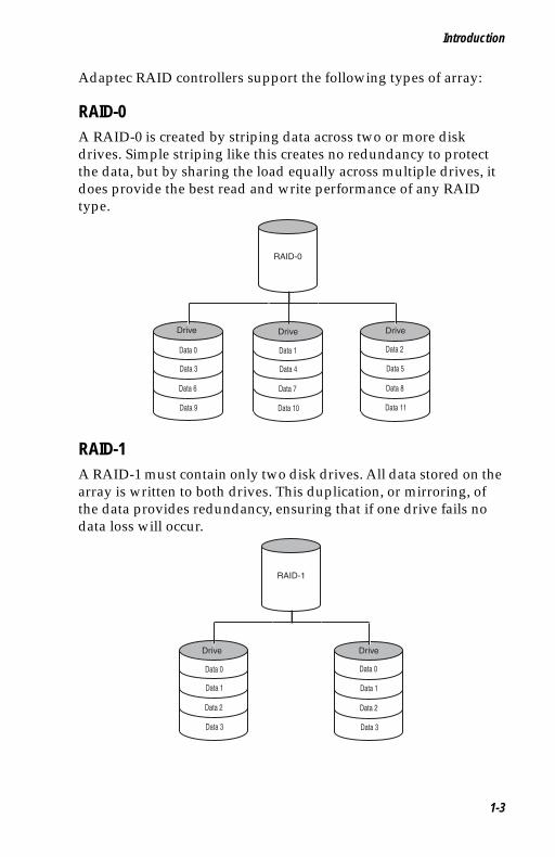
RAID-0A RAID-0 is created by striping data across two or more disk drives. Simple striping like this creates no redundancy to protect the data, but by sharing the load equally across multiple drives, it does provide the best read and write performance of any RAID type.
RAID-1A RAID-1 must contain only two disk drives. All data stored on the array is written to both drives. This duplication, or mirroring, of the data provides redundancy, ensuring that if one drive fails no data loss will occur.
Data 0
Data 3
Data 6
Data 9
RAID-0
Data 2
Data 5
Data 8
Data 11
Data 1
Data 4
Data 7
Data 10
Drive Drive Drive
Data 0
Data 1
Data 2
Data 3
RAID-1
Data 0
Data 1
Data 2
Data 3
Drive Drive
1-3
Adaptec SCSI RAID 2120S/2200S Software User’s Guide
UG.book Page 4 Saturday, October 26, 2002 12:08 PM
The cost of this redundancy is inefficient use of capacity, because all data is written to both drives, only half of the total capacity is available.
RAID-1 offers no write performance advantage over a single drive, but read performance benefits from being able to share the load between two drives.
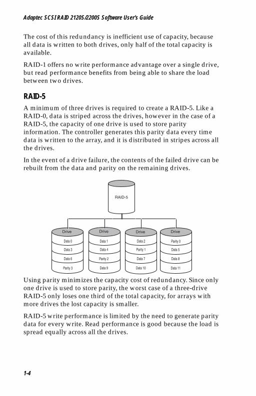
RAID-5A minimum of three drives is required to create a RAID-5. Like a RAID-0, data is striped across the drives, however in the case of a RAID-5, the capacity of one drive is used to store parity information. The controller generates this parity data every time data is written to the array, and it is distributed in stripes across all the drives.
In the event of a drive failure, the contents of the failed drive can be rebuilt from the data and parity on the remaining drives.
Using parity minimizes the capacity cost of redundancy. Since only one drive is used to store parity, the worst case of a three-drive RAID-5 only loses one third of the total capacity, for arrays with more drives the lost capacity is smaller.
RAID-5 write performance is limited by the need to generate parity data for every write. Read performance is good because the load is spread equally across all the drives.
Data 0
Data 3
Data 6
Parity 3
RAID-5
Parity 0
Data 5
Data 8
Data 11
Data 2
Parity 1
Data 7
Data 10
Data 1
Data 4
Parity 2
Data 9
Drive Drive Drive Drive
1-4
Introduction
UG.book Page 5 Saturday, October 26, 2002 12:08 PM
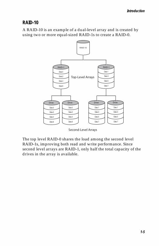
RAID-10A RAID-10 is an example of a dual-level array and is created by using two or more equal-sized RAID-1s to create a RAID-0.
The top level RAID-0 shares the load among the second level RAID-1s, improving both read and write performance. Since second level arrays are RAID-1, only half the total capacity of the drives in the array is available.
RAID-10
Data 1
Data 3
Data 5
Data 7
Drive
Data 1
Data 3
Data 5
Data 7
Drive
Data 0
Data 2
Data 4
Data 6
Drive
Data 0
Data 2
Data 4
Data 6
Drive
Data 0
Data 2
Data 4
Data 6
RAID-1
Data 1
Data 3
Data 5
Data 7
RAID-1
Top-Level Arrays
Second-Level Arrays
1-5
Adaptec SCSI RAID 2120S/2200S Software User’s Guide
UG.book Page 6 Saturday, October 26, 2002 12:08 PM
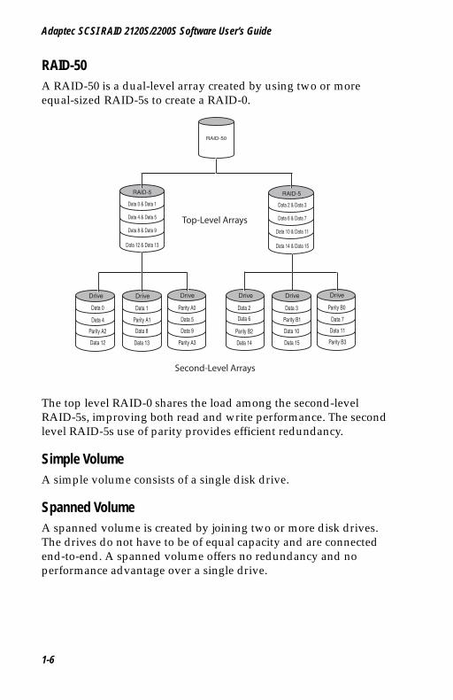
RAID-50A RAID-50 is a dual-level array created by using two or more equal-sized RAID-5s to create a RAID-0.
The top level RAID-0 shares the load among the second-level RAID-5s, improving both read and write performance. The second level RAID-5s use of parity provides efficient redundancy.
Simple VolumeA simple volume consists of a single disk drive.
Spanned VolumeA spanned volume is created by joining two or more disk drives. The drives do not have to be of equal capacity and are connected end-to-end. A spanned volume offers no redundancy and no performance advantage over a single drive.
RAID-50
Parity B0
Data 7
Data 11
Parity B3
Drive
Data 4 & Data 5
RAID-5 RAID-5
Data 3
Parity B1
Data 10
Data 15
Drive
Data 2
Data 6
Parity B2
Data 14
Drive
Parity A0
Data 5
Data 9
Parity A3
Drive
Data 1
Parity A1
Data 8
Data 13
Drive
Data 0
Data 4
Parity A2
Data 12
Drive
Data 0 & Data 1
Data 8 & Data 9
Data 12 & Data 13
Data 2 & Data 3
Data 6 & Data 7
Data 10 & Data 11
Data 14 & Data 15
Top-Level Arrays
Second-Level Arrays
1-6

Introduction
UG.book Page 7 Saturday, October 26, 2002 12:08 PM
RAID VolumeA RAID volume is created by joining two or more single-level arrays of the same RAID type. Unlike dual-level arrays, the arrays in a RAID volume do not have to be of equal capacity. In direct contrast to dual-level arrays, the second-level arrays in a RAID volume are not striped together, instead they are connected end-to-end.
Features
Optimized Disk UtilizationFor simplicity the explanations of the various types of array above describe the arrays in terms of complete drives. Typically arrays use the same size drives, or if drives of varying capacities are used, the capacity used on each drive is limited to that of lowest capacity drive.
For example, a RAID-1 constructed using one 18G and one 9G drive will only use half of the capacity of the larger drive and the array will be limited to 9G.
Adaptec’s Optimized Disk Utilization feature allows arrays to be created using portion of drives. These sections of drives are known as segments and are created automatically during the array creation process.
Within a given array each segment will be the same size, but the segment size does not have to equal the capacity of the smallest drive.
Any unused capacity on drives is known as available space, and can be used in another array or arrays.
Adaptec RAID controllers use a small segment at the beginning of each drive connected to them to store information about the drives and arrays attached to the controller. This area is known as the RAID signature.
Array ReconfigurationAdaptec RAID controllers support modifying existing arrays by expansion, migration from one array type to another and changing the stripe size.
1-7
Adaptec SCSI RAID 2120S/2200S Software User’s Guide
UG.book Page 8 Saturday, October 26, 2002 12:08 PM
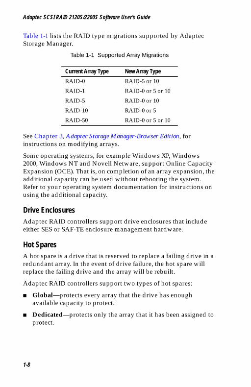
Table 1-1 lists the RAID type migrations supported by Adaptec Storage Manager.
Table 1-1 Supported Array Migrations
See Chapter 3, Adaptec Storage Manager-Browser Edition, for instructions on modifying arrays.
Some operating systems, for example Windows XP, Windows 2000, Windows NT and Novell Netware, support Online Capacity Expansion (OCE). That is, on completion of an array expansion, the additional capacity can be used without rebooting the system. Refer to your operating system documentation for instructions on using the additional capacity.
Drive EnclosuresAdaptec RAID controllers support drive enclosures that include either SES or SAF-TE enclosure management hardware.
Hot SparesA hot spare is a drive that is reserved to replace a failing drive in a redundant array. In the event of drive failure, the hot spare will replace the failing drive and the array will be rebuilt.
Adaptec RAID controllers support two types of hot spares:
■ Global—protects every array that the drive has enough available capacity to protect.
■ Dedicated—protects only the array that it has been assigned to protect.
Current Array Type New Array Type
RAID-0 RAID-5 or 10
RAID-1 RAID-0 or 5 or 10
RAID-5 RAID-0 or 10
RAID-10 RAID-0 or 5
RAID-50 RAID-0 or 5 or 10
1-8
Introduction
UG.book Page 9 Saturday, October 26, 2002 12:08 PM
Automatic Rebuild On ReplacementAdaptec RAID controllers support a feature known as Automatic rebuild on replacement. This may be useful in the event of a drive failure if no hot spare is available and the failing drive is in an SES or SAF-TE enabled drive enclosure.
When this feature is enabled (default) a rebuild of any redundant array that the failed drive was a member of will be triggered automatically by simply removing the failure drive and replacing it with a new drive.
SCSI Devices SupportedIn addition to SCSI hard disk drives, Adaptec RAID controllers support a wide range of SCSI devices, from CD-ROMs and tape drives to scanners and removable media drives.
Supported ControllersThe majority of this chapter and all the other documentation supplied with your controller describes the capabilities of the RAID controllers listed in the left column of Table 1-2. Adaptec Storage Manager-Browser Edition also supports other Adaptec RAID controllers provided the RAID management software supplied with those cards, Adaptec Storage Manager or Adaptec Storage Manager Pro is already installed on the system.
1-9

Adaptec SCSI RAID 2120S/2200S Software User’s Guide
UG.book Page 10 Saturday, October 26, 2002 12:08 PM
Adaptec RAID controllers supported by Adaptec Storage Manager-Browser Edition are listed in Table 1-2.
Table 1-2 Supported Adaptec RAID Controllers
1 In order for Adaptec Storage Manager - Browser Edition to support an Adaptec SCSI RAID 5400S controller, Adaptec Storage Manager Pro must be uninstalled before Adaptec Storage Manager - Browser Edition is installed.
2 In order for Adaptec Storage Manager - Browser Edition to support any controller in this column, Adaptec Storage Manager or Storage Manager Pro must be installed. Uninstalling Adaptec Storage Manager or Storage Manger Pro will remove support for that controller.
Installing Adaptec Storage Manager-Browser Edition on a system with one of the standard feature set cards installed does not add any new functionality to the existing controller.
For a detailed description of the capabilities of any controller, refer to the documentation supplied with that controller.
Advanced Feature Set Standard Feature Set2
Adaptec SCSI RAID 2200S, 2120S, 5400S1
Adaptec SCSI RAID 2000S, 2005S, 2010S, 2015S, 2100S, 2210S, 3200S, 3210S, 3400S, 3410SAdaptec ATA RAID 2400A
1-10
UG.book Page 1 Saturday, October 26, 2002 12:08 PM
2
Using Adaptec RAID ConfigurationIn this ChapterThe Adaptec RAID Configuration Utility (ARC) is an embedded BIOS utility that includes an Array Configuration Utility (ACU) that allows the creation, configuration, and management of arrays. Also included are SCSISelect which supports changing SCSI device and controller settings, and Disk Utilities to low-level format or verify disk media.
Adaptec also provides a standalone utility to create, configure, and manage arrays from an MS-DOS prompt. This utility is called Array Configuration Utility (ACU) for MS-DOS and it is described in the Adaptec SCSI RAID Software Reference Guide. This chapter describes only the functionality of the BIOS-based ACU.
To run ARC, when prompted by the following message during the system boot process press Ctrl+A :
Press <Ctrl><A> for Adaptec RAID Configuration Utility
Using the Array Configuration Utility 2-2
Using the SCSISelect Utility 2-10
Using the Controller Configuration Utility 2-11
Using the SCSI Configuration Utility 2-13
Using the Disk Utilities 2-15
Viewing the Event Log 2-16
2-1
Adaptec SCSI RAID 2120S/2200S Software User’s Guide
UG.book Page 2 Saturday, October 26, 2002 12:08 PM
The Adaptec SCSI RAID Controller menu appears, presenting the following options:
■ Array Configuration Utility
■ SCSISelect Utility
■ Disk Utilities
To select an option from this menu or from any of the menus within ARC, move the cursor to the option with the Up/Down arrow keys and press Enter. In some cases, selecting an option displays another menu. You can return to the previous menu at any time by pressing Esc.
The following sections discuss each of these menu options.
Using the Array Configuration UtilityThe Array Configuration Utility (ACU) enables you to manage, create, and delete arrays from the controller’s BIOS. You can also initialize and rescan drives.
You can use the ACU to create a bootable array for the system. We recommend that you configure the system to boot from an array instead of from a single disk to take advantage of the redundancy and performance features of arrays. For details on creating a bootable array, see Deleting Arrays on page 2-4.
Note: If you are changing the configuration of a system that is already in use on a network, log all users off the system and shut it down in an orderly manner before you start the ACU.
Managing ArraysUse the Manage Arrays option to view array properties and members, make an array the boot array, manage failover assignments, and delete arrays. The following sections describe these operations in greater detail.
Viewing Array Properties
To view the properties of an existing array:
1 At the BIOS prompt, press Ctrl+A.
2-2

Using Adaptec RAID Configuration
UG.book Page 3 Saturday, October 26, 2002 12:08 PM
2 From the ARC menu, select Array Configuration Utility.
3 From the ACU menu, select Manage Arrays.
4 From the List of Arrays dialog box, select the array you want to view information on and press Enter.
The Array Properties dialog box appears, showing detailed information on the array. The physical disks associated with the array are displayed here, except in the case of dual-level arrays (RAID 10 and RAID 50, for example). For dual-level arrays, highlight the displayed member and press Enter to display the second level. Press Enter again to display the physical disks associated with the array.
Note: A failed drive is displayed in a different text color.
5 Press Esc to return to the previous menu.
Making an Array Bootable
You can make an array bootable so that the system boots from the array instead of from a stand-alone (single) disk.
To make an array bootable:
1 At the BIOS prompt, press Ctrl+A.
2 From the ARC menu, select Array Configuration Utility.
3 From the ACU menu, select Manage Arrays.
4 Select the array you want to make bootable and type Ctrl+B. This changes the selected array’s number to 00, making it the controller’s boot array.
5 Reboot the system.
If you are booting from the controller, bear in mind the following:
■ If the controller is not a boot device, you can disable its runtime BIOS, see page 2-11. When the BIOS is disabled it will not occupy any of the expansion ROM region of the system’s memory map. This may be useful if there are several cards with an expansion ROM (BIOS) in the system.
2-3

Adaptec SCSI RAID 2120S/2200S Software User’s Guide
UG.book Page 4 Saturday, October 26, 2002 12:08 PM
■ You cannot make a non-00 array bootable if the array is in a build/verify or reconfiguration process.
Caution: The controller always uses the lowest numbered array as its bootable array. If you delete array 00 for any reason, the next lowest numbered array will become the bootable array. Use the Ctrl+B option to mark the correct array as the bootable array (by making it array 00).
If you want to boot from a stand-alone (single) disk drive, first create a volume on that disk.
The system BIOS provides additional tools to modify the boot order. For more information, refer to your system documentation.
Deleting Arrays
Caution: Back up the data on an array before you delete it. All data on the array is lost when you delete the array. Deleted arrays cannot be restored.
To delete an existing array:
1 At the BIOS prompt, press Ctrl+A.
2 From the ARC menu, select Array Configuration Utility.
3 From the ACU menu, select Manage Arrays.
4 Select the array you wish to delete and press Delete.
5 In the Array Properties dialog box, press Delete again and press Enter. The following prompt is displayed:
Warning!! Deleting will erase all data from the array.Do you still want to continue? (Yes/No):
6 Press Yes to delete the array or No to return to the previous menu. At the Array Properties dialog box, select Delete again and press Enter.
7 Press Esc to return to the previous menu.
!
!
2-4
Using Adaptec RAID Configuration
UG.book Page 5 Saturday, October 26, 2002 12:08 PM
Managing Failover Drive Assignments
To assign a hot spare drive to an array:
1 Select Manage Arrays from the Main menu.
2 On the List of Arrays dialog box, select the array you want to assign a hot spare drive to, and type Ctrl+S. The Hotspare Management for Array dialog box is displayed, which shows the drives that can be assigned as hot spare drives.
3 Select a drive and press the Insert key to assign the drive as a hot spare. The specified drive is displayed in the Assigned Hotspares drives list.
4 Press Enter to save the hot spare drive assignment. The following prompt is displayed:
Have you finished managing Hotspare drives?
5 Type Y (yes) to return to the Main menu.
To remove an assigned hot spare drive from an array:
1 Select Manage Arrays from the Main menu.
2 In the List of Arrays dialog box, select the array from which you want to remove the assigned hot spare drive and typeCtrl+S. The Hotspare Management for Array dialog box is displayed, which shows a list of drives that can be assigned as hot spare drives and a list of drives that are assigned as hot spare drives.
3 From the Assigned Hotspares drives list, select the drive to be removed, then press Delete. The specified drive is displayed in the Select Hotspares drives list.
4 Press Enter to save the removed hot spare drive assignment. The following prompt is displayed:
Have you finished managing Hotspare drives?
5 Type Y (yes) to return to the Main menu.
2-5
Adaptec SCSI RAID 2120S/2200S Software User’s Guide
UG.book Page 6 Saturday, October 26, 2002 12:08 PM
Creating ArraysBefore creating arrays, make sure the disks for the array are connected and installed in your system (or enclosure). Note that any disks with MS-DOS partitions, disks with no usable space, or disks that are uninitialized appear dimmed and cannot be used for creating a new array. For information on how to initialize a disk drive, see page 2-9.
To create an array:
1 Shut down and reboot the system.
2 At the BIOS prompt, press Ctrl+A.
3 From the ARC menu, select Array Configuration Utility.
4 From the ACU menu, select Create Array.
5 Use the Left/Right arrow keys to select a channel.
6 Select the disks for the new array and press Insert. ACU displays the largest usable space available for each disk. You can use available space from multiple disks for the new array.
Note: Consult Table 2-1 on page 2-7 for the maximum number of drives that can be used for each RAID level.
To deselect any disk, highlight the disk and press Delete.
Note: ACU cannot reliably find disks or enclosures that were powered up after system power-up.
7 Press Enter when all disks for the new array are selected. The Array Properties menu displays.
If you install a controller into a system that has been powered down, on startup the BIOS will announce the detected configuration changes. If the controller does not consider these changes risky it will present a confirmation prompt and will auto-confirm if there has been no operator input in 30 seconds. If the controller considers that the changes are risky, you will be prompted for further action.
2-6

Using Adaptec RAID Configuration
UG.book Page 7 Saturday, October 26, 2002 12:08 PM
Assigning Array Properties
Note that you cannot change array properties from the ACU once the array is created. To change array properties once the array is created, use Adaptec Storage Manager.
To assign properties to the new array:
1 In the Array Properties menu, select an array type and press Enter. Note that only those array types available according to the number of drives selected are displayed. For a description of the supported array types, see the installation guide shipped with your controller.
The physical SCSI limitation for the controller is 15 drives per channel. The maximum number of drives allowed and minimum number of drives required depends on the RAID level. Consult Table 2-1 for a listing of this information.
2 Type in an optional label for the array and press Enter.
3 Enter the desired array size. The maximum array size available based on the segments you selected is displayed automatically. If you want to designate a different array size, type the desired array size and select MB (megabytes), GB (gigabytes), or TB (terabytes) from the drop-down list. If the available space from the selected segments is greater than the size specified, the remaining space will be available for use in other arrays.
Table 2-1 RAID Levels and Drives Information
RAID Level Maximum Drives Allowed
Minimum Drives Required
Volume 32 1
RAID 0 48 2
RAID 1 2 2
RAID 5 16 3
RAID 10 48 4
RAID 50 48 6
2-7
Adaptec SCSI RAID 2120S/2200S Software User’s Guide
UG.book Page 8 Saturday, October 26, 2002 12:08 PM
4 Select the desired stripe size. The allowable stripe sizes are 16, 32, and 64 KB (the default). For RAID 50 arrays, 64 KB is the only stripe size supported by ACU. The default stripe size gives the best overall performance in most network environments.
5 Specify whether you want to enable read caching for the array.
This option should always be enabled to optimize performance, unless your application is doing completely random reads, which is unlikely.
6 Specify if you want to enable write caching for the array.
Note: By design, some controllers do not allow the use of write caching. In such cases, the controller will not activate write caching, regardless of the write cache setting. If this is the case a message will be displayed that tells you the settings have been recorded but have no effect.
Write caching options (if supported) consist of the following:
■ Enable when protected—If supported, enables the write cache only when a battery is present and the battery’s charge status is OK.
■ Enable always—If supported, enables the write cache even if no battery is present or the battery’s charge status is not OK. Note that setting an array’s write cache property to Enable always might result in data loss or corruption if power to the controller is lost when no battery is present or the battery loses its charge.
■ Disable—Disables use of the write cache.
7 When you are finished, press Done.
2-8
Using Adaptec RAID Configuration
UG.book Page 9 Saturday, October 26, 2002 12:08 PM
Initializing Disk DrivesIf an installed disk does not appear in the disk selection list for creating a new array or if it appears grayed out, you may have to initialize it before you can use it as part of an array.
Caution: Initializing a disk overwrites the partition table on the disk and makes any data on the disk inaccessible. If the drive is used in an array, you may not be able to use the array again. Do not initialize a disk that is part of a boot array. The boot array is lowest numbered array (normally 00) in the List of Arrays dialog box.
See Viewing Array Properties on page 2-2 for information on determining which disks are associated with a particular array.
To initialize drives:
1 At the BIOS prompt, press Ctrl+A.
2 From the ARC menu, select Array Configuration Utility.
3 Select Initialize Drives.
4 Use the Right/Left arrow keys to select a channel.
5 Use the up and down arrow keys to highlight the disk you wish to initialize and press Insert.
6 Repeat step 5 until all the drives to be initialized are selected.
7 Press Enter.
8 Read the warning message and ensure that you have selected the correct disk drives to initialize. Type Y to continue.
Rescanning Disk DrivesTo rescan the drives connected to the controller:
1 At the BIOS prompt, press Ctrl+A.
2 From the ARC menu, select Array Configuration Utility.
3 Select Rescan Drives.
!
2-9
Adaptec SCSI RAID 2120S/2200S Software User’s Guide
UG.book Page 10 Saturday, October 26, 2002 12:08 PM
Using the SCSISelect UtilityThe SCSISelect Utility enables you to change device and controller settings without opening the system chassis or handling the card. If you want to view or change the current settings, see Starting and Exiting SCSISelect on page 2-10. For detailed descriptions of each setting, see Using the Controller Configuration Utility on page 2-11.
Starting and Exiting SCSISelectTo start SCSISelect:
1 When you turn on or reboot your system, press Ctrl+A to access the Adaptec RAID Configuration (ARC) utilities when prompted by the following message:Press <Ctrl><A> for Adaptec RAID Configuration Utility
2 If multiple controllers are installed, select the controller you want to configure and press Enter.
3 From the ARC menu, select SCSISelect Utility.
The Controller Configuration and SCSI Configuration menu options are displayed.
To exit SCSISelect, press Esc until a message prompts you to exit. (If you changed any host adapter settings, you are prompted to save the changes before you exit.) Select Yes to exit and reboot the system. Any changes you made take effect after the system boots.
Using the SCSISelect MenusTo select a SCSISelect menu option, move the cursor to the option with the Up/Down arrow keys and press Enter. In some cases, selecting an option displays another menu. You can return to the previous menu at any time by pressing Esc.
To restore the original SCSISelect default values, press F6 from the Configure/View Host Adapter Settings screen.
2-10
Using Adaptec RAID Configuration
UG.book Page 11 Saturday, October 26, 2002 12:08 PM
Using the Controller Configuration UtilityTo access the Controller Configuration Utility:
1 When you turn on or reboot your system, press Ctrl+A to access ARC when prompted by the following message:
Press <Ctrl><A> for Adaptec RAID Configuration Utility
2 If multiple controllers are installed, select the controller you want to configure and press Enter.
3 From the ARC menu, select SCSISelect Utility.
The Controller Configuration and SCSI Configuration menu options are displayed.
4 Select Controller Configuration.
You can modify the following Controller Interface Definitions:
■ Drives Write Cache — Enables or disables the write-back cache feature of all SCSI disk drives connected to the controller. If Disabled, the controller will disable the write-back cache of all attached drives. If Enabled, then the controller will enable the write-back cache of all attached drives. If Drive Default, then the controller will not change the write-back cache setting of any attached drives. The default is Drive Default.
Caution: Disk drives with write-back cache enabled do not have the benefit of battery protection and could lose or corrupt data as a result of unexpected power loss or drive removal.
Certain controllers may not support drives write cache. In those cases where drives write cache is not supported, setting the option to Enabled has no effect.
■ Runtime BIOS — Enables or disables the controller’s runtime BIOS. The BIOS must be enabled if you want to boot from the controller.
!
2-11
Adaptec SCSI RAID 2120S/2200S Software User’s Guide
UG.book Page 12 Saturday, October 26, 2002 12:08 PM
If Runtime BIOS is enabled and the BBS Support and Array-based BBS Support options are disabled, the controller BIOS is enabled and will post the lowest numbered array (typically 00) on the first controller found as a legacy Int13h bootable hard disk drive.
The default is Enabled.
■ Automatic rebuild on replacement — If enabled, this option lets you replace a failed drive in the same enclosure slot in a RAID 1, RAID 5, RAID 10 or RAID 50. Then the BIOS recognizes that the failed drive has been replaced, initializes the new disk, and immediately initiates a failover. Note that this option is supported only for disks in SAF-TE enclosures or backplanes.
The default is Enabled.
■ Array Background Consistency Check — If enabled, this option forces the controller to constantly check all portions of disks used by all arrays to see if the disks can return data from the blocks. On a fully-redundant RAID 5 with no bad segments, the controller repairs any data that cannot be read.
The default is Disabled.
■ BBS Support — If the Runtime BIOS option and this option are enabled and the Array-based BBS Support option is disabled, the lowest numbered array on each controller is posted as a BBS (BIOS Boot Specification) device.
The default is Enabled.
■ Array-based BBS Support — If Runtime BIOS, BBS Support and this option are all enabled, the lowest numbered three devices (typically 00, 01 and 02) on each controller in the system are posted as BBS devices.
In a BBS-enabled system with two controllers installed, and at least three arrays on each controller, if Array based BBS support is enabled the “Hard drive boot order menu” will include six entries for arrays connected to the two RAID controllers.
2-12
Using Adaptec RAID Configuration
UG.book Page 13 Saturday, October 26, 2002 12:08 PM
The Ctrl-B option in ACU moves any array to be array 00. Using this option repeatedly allows any boot order to be chosen.
The default is Disabled.
■ Physical Drives Display during POST— The default is Disabled.
■ CD-ROM Boot Support — The default is Enabled.
■ Removable Media Devices Support — The default is Enabled.
■ Alarm Control — The default is Enabled.
You cannot set the following options:
■ NVRAM State — Displays the current status of the NVRAM cache. This option is available only for controllers that have a battery and is for display only. In normal operation it will display Clean.
■ Controller Memory Size — Displays the amount of memory installed on the controller.
Using the SCSI Configuration UtilityThe SCSI Configuration Utility enables you to modify the SCSI Channel Interface Definitions and SCSI Device Configuration Options.
To access the SCSI Configuration Utility:
1 When you turn on or reboot your system, press Ctrl+A to access the Adaptec RAID Configuration (ARC) utilities when prompted by the following message:
Press <Ctrl><A> for Adaptec RAID Configuration Utility
2 If multiple controllers are installed, select the controller you want to configure and press Enter.
3 From the ARC menu, select SCSISelect Utility.
The Controller Configuration and SCSI Configuration menu options are displayed.
4 Select SCSI Configuration.
2-13

Adaptec SCSI RAID 2120S/2200S Software User’s Guide
UG.book Page 14 Saturday, October 26, 2002 12:08 PM
5 The Select SCSI Channel menu is displayed. Select the appropriate channel from this menu.
You can modify the following SCSI Channel Interface Definitions:
■ Controller SCSI Channel ID — Sets the controller’s SCSI ID. We recommend that you leave the controller set to SCSI ID 7, which gives it the highest priority on the SCSI channel.
■ SCSI Parity Checking — Determines whether the controller verifies the accuracy of data transfer on the SCSI channel. You should disable SCSI Parity Checking on the controller and all SCSI devices if any SCSI device supported by the controller does not support SCSI parity; otherwise, leave it enabled. Most SCSI devices do support SCSI parity. If you are not sure whether a device supports SCSI parity, consult the documentation for the device.
■ Controller SCSI Channel Termination — Sets termination on the controller card. We recommend that you leave the default setting of Auto Mode.
■ SCSI Device Configuration — For information about these options, see the section, SCSI Device Configuration Options.
SCSI Device Configuration Options
The SCSI device settings allow you to configure certain parameters for each device on the SCSI channel. To configure settings for a specific device, you must know the SCSI ID assigned to that device. If you are not sure of the SCSI ID, see Using the Disk Utilities on page 2-15.
■ Maximum Transfer Rate — Determines the maximum data transfer rate that the SCSI channel supports. The maximum effective data transfer rate is doubled when Initiate Wide Negotiation is set to Yes and 16-bit devices are attached. (Initiate Wide Negotiation has no effect with 8-bit devices.)
■ Enable Disconnection — Determines whether the SCSI channel allows the SCSI device to disconnect from the SCSI channel (sometimes called Disconnect/Reconnect or Reselection). This option should be enabled for maximum performance. The default is yes.
2-14

Using Adaptec RAID Configuration
UG.book Page 15 Saturday, October 26, 2002 12:08 PM
■ Initiate Wide Negotiation — Determines whether the SCSI channel attempts 16-bit data transfer instead of 8-bit data transfer. The effective data transfer rate is doubled when 16-bit data transfer is used. The default is yes.
■ QAS — Determines whether QAS (Quick Arbitration and Selection) is used to eliminate overhead and speed up data transfers on the SCSI bus. The default is yes.
■ Packetized — Determines whether SCSI packetization (encapsulation) is used to reduce overhead and speed data transfer. The packetized SCSI protocol provides a method for transferring command and status information at the maximum rate. The default is yes.
Using the Disk UtilitiesThe BIOS-based Disk Utilities enable you to low-level format or verify the disk media of your SCSI hard disks.
To access the disk utilities:
1 When you turn on or reboot your system, press Ctrl+A to access the Adaptec RAID Configuration (ARC) utilities when prompted by the following message:
Press <Ctrl><A> for Adaptec RAID Configuration Utility
2 If multiple controllers are installed, select the controller you want to configure and press Enter.
3 From the ARC menu, select Disk Utilities.
4 Select the desired channel and press Enter.
After the option is selected, a list of all SCSI IDs and the devices at each ID is displayed. After selecting a specific ID and device, a small menu appears, displaying the following options:
■ Format Disk—Performs a low-level format on a hard disk drive. Each hard disk drive must be low-level formatted before you can use your operating system’s partitioning and file preparation utilities, such as MS-DOS Fdisk and Format.
Most SCSI disk devices are preformatted at the factory and do not need to be formatted again. The Format Disk option is compatible with the vast majority of SCSI disk drives.
2-15
Adaptec SCSI RAID 2120S/2200S Software User’s Guide
UG.book Page 16 Saturday, October 26, 2002 12:08 PM
The controller should not be powered off or rebooted during a disk format. Doing so may render the disk unusable until the format is manually restarted and completed.
Caution: A low-level format destroys all data on the drive. Be sure to back up your data before performing this operation. Once started, you cannot abort a low-level format.
■ Verify Disk Media — Scans the media of a disk drive for defects. If the utility finds bad blocks on the media, it prompts you to reassign them. If you select yes, the utility remaps the recoverable defects and no longer uses those blocks. You can press Esc at any time to abort the utility.
Viewing the Event LogThe BIOS-based event log stores all firmware events (configuration changes, array creation, boot activity, and so on).
To access the event log:
1 When you turn on or reboot your system, press Ctrl+A to access the ARC when prompted by the following message:Press <Ctrl><A> for Adaptec RAID Configuration Utility
2 If multiple controllers are installed, select the controller you want to configure and press Enter.
3 From the ARC menu, press Ctrl+P.
4 The Controller Service Menu appears, including the option Controller Log Information.
5 Select Controller Log Information and press Enter. The current log is displayed.
!
2-16
UG.book Page 1 Saturday, October 26, 2002 12:08 PM
3
Adaptec Storage Manager-Browser EditionIn this ChapterAbout Adaptec Storage Manager 3-2
Login to Adaptec Storage Manager 3-4
Installing a Security Certificate 3-6
Understanding Adaptec Storage Manager 3-7
Creating Arrays 3-12
Creating and Deleting Hot Spares 3-16
Deleting Arrays 3-17
Modifying Arrays 3-17
User Interface Options 3-19
Viewing Events 3-20
Help 3-20
Displaying and Modifying Properties 3-21
Viewing and Creating Tasks 3-27
About Adaptec Storage Manager Notifier Service 3-29
Enabling and Configuring the Notifier Service 3-31
3-1
Adaptec SCSI RAID 2120S/2200S Software User’s Guide
UG.book Page 2 Saturday, October 26, 2002 12:08 PM
About Adaptec Storage ManagerAdaptec Storage Manager - Browser Edition is a web-based application that supports managing storage either locally (at the system in which the storage controller is installed), or remotely (from another system).
Any system containing an Adaptec storage controller that has Windows or Linux and a supported browser installed can be managed locally. Supported browsers are:
■ Windows
■ Internet Explorer (IE) 5.0 or later
■ Netscape 6 or later
■ Linux
■ Adaptec-supplied and installed version of Mozilla
■ Netscape 6 or later
These same Windows and Linux systems can also be managed remotely. This can be achieved in two ways:
■ Installing Adaptec Storage Manager on the remote system.
■ Directing the browser on the remote system to the system you want to manage.
Note: If you want to manage from a Linux system it is recommended that you install Adaptec Storage Manager on the remote system and use the Adaptec-supplied version of Mozilla as the browser.
For Unix and NetWare installations, Adaptec Storage Manager can only be used to manage the system remotely. Local management is supported using the CLI.
The following explanation of the software architecture will help you understand the possible configurations and determine which one is most appropriate for your application. Installation instructions are included in the Adaptec SCSI RAID Installation Guide supplied on the same CD as this document.
3-2
Adaptec Storage Manager-Browser Edition
UG.book Page 3 Saturday, October 26, 2002 12:08 PM
Adaptec Storage Manager - Browser Edition consists of the three major components:
■ A supported web browser, which should already be installed on the system.
■ The Adaptec web service which supplies content displayed on the web browser.
■ An Adaptec-supplied storage agent.
For a locally managed system, all three components will be installed on the same system.
To support the remote management configurations described below, all components must be installed on systems that have a TCP/IP connection through which the other component(s) can be accessed.
All communication uses Secure-HTTP (S-HTTP) or SSL protocols to encrypt all data transmitted and ensure security. Connection over an Ethernet network, a corporate WAN, or VPN are supported.
Several remote management configurations are possible:
■ The browser will always be on a remote system.
■ The storage agent will always be installed on the system with the storage controller installed.
■ The web service can be installed on the same remote system as the browser, the system with the storage controller installed on a third system.
The storage agent is supplied for all supported operating systems, while the web service is available only for Windows and Linux. In order for Adaptec Storage Manager - Browser Edition to manage storage on a UNIX or NetWare system, the storage agent must communicate with the Adaptec web service on a separate Windows or Linux system.
In this configuration, the Windows or Linux system can either be used to manage the RAID controller, or act as a server communicating with a supported browser on a third system.
3-3

Adaptec SCSI RAID 2120S/2200S Software User’s Guide
UG.book Page 4 Saturday, October 26, 2002 12:08 PM
Login to Adaptec Storage ManagerTo login to a system with Adaptec Storage Manager installed:
1 Start Adaptec Storage Manager - Browser Edition. In Windows, you will find the application by clicking Start > Programs > SMBE > Adaptec Storage Manager - Browser Edition. In Linux, you will find it by clicking Start > System > Adaptec Storage Manager.
2 The first screen presented is the Login screen shown below. Enter the host name or IP address of the system you want to manage and the username and password you would use to log into that system.
3 Click Login.
Note: When you run Adaptec Storage Manager for the first time after installation you will have to install a security certificate. For instructions see Installing a Security Certificate on page 3-6.
3-4
Adaptec Storage Manager-Browser Edition
UG.book Page 5 Saturday, October 26, 2002 12:08 PM
To login from any system with a web browser:
1 Start the web browser application and type the IP address for the system you want to access in the address bar and press Enter. Example: https://10.6.3.14:3513/adaptec.
When connection to the remote system is established the Adaptec Storage Manager Login screen will appear.
Note: If you are using a proxy server to access the internet, you will need to bypass the proxy server to access the Adaptec Storage Manager web server. In IE, if you know the IP address of the system you want to manage remotely, choose Tools > Internet Options > Connections>LAN Settings > select Use a proxy server for your LAN >Advanced, and type the managed system’s IP address in the Exceptions section.
In Netscape, if you know the IP address of the system you want to manage remotely, choose Edit> Preferences > Advanced> Proxies > Manual proxy configuration > No Proxy For, type the managed system’s IP address.
2 Enter the host name or IP address of the system you want to manage and the administrative username and password that you would normally use to log into that system.
3 Click Login.
Note: When you run Adaptec Storage Manager for the first time after installation you will have to install a security certificate. For instructions, see Installing a Security Certificate on page 3-6.
3-5
Adaptec SCSI RAID 2120S/2200S Software User’s Guide
UG.book Page 6 Saturday, October 26, 2002 12:08 PM
Installing a Security CertificateWhen using Adaptec Storage Manager for the first time after installation, you need to create a security certificate. Follow the steps below to create the certificate:
1 When the Security Alert window appears, click View Certificate.
2 On the Certificate window that appears, click Install Certificate.
3 On the Certificate Import wizard window that appears, click Next.
4 The Certificate Import wizard window’s contents will change. Use the default Automatically select the certificate store, click Next.
5 On the root Certificate Store window, click Yes.
6 Another small Certificate Import wizard window will appear with only an OK button, click OK.
7 You will be returned to the Certificate window from step 2. Click OK.
8 You will be returned to the Security Alert window from step 1. Click Yes. This will finish the creation and storage of the certificate.
3-6
Adaptec Storage Manager-Browser Edition
UG.book Page 7 Saturday, October 26, 2002 12:08 PM
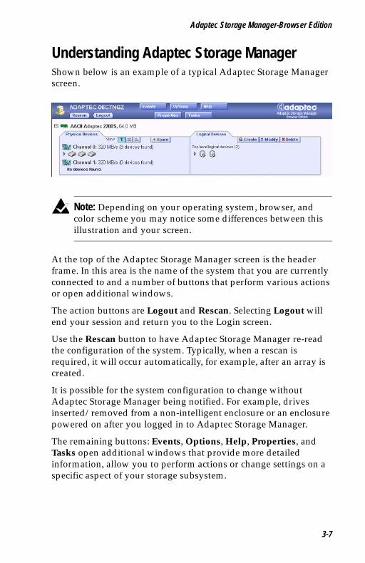
Understanding Adaptec Storage Manager Shown below is an example of a typical Adaptec Storage Manager screen..
Note: Depending on your operating system, browser, and color scheme you may notice some differences between this illustration and your screen.
At the top of the Adaptec Storage Manager screen is the header frame. In this area is the name of the system that you are currently connected to and a number of buttons that perform various actions or open additional windows.
The action buttons are Logout and Rescan. Selecting Logout will end your session and return you to the Login screen.
Use the Rescan button to have Adaptec Storage Manager re-read the configuration of the system. Typically, when a rescan is required, it will occur automatically, for example, after an array is created.
It is possible for the system configuration to change without Adaptec Storage Manager being notified. For example, drives inserted/removed from a non-intelligent enclosure or an enclosure powered on after you logged in to Adaptec Storage Manager.
The remaining buttons: Events, Options, Help, Properties, and Tasks open additional windows that provide more detailed information, allow you to perform actions or change settings on a specific aspect of your storage subsystem.
3-7
Adaptec SCSI RAID 2120S/2200S Software User’s Guide
UG.book Page 8 Saturday, October 26, 2002 12:08 PM
For detailed instructions on using these buttons, see the sections Viewing Events on page 3-20, User Interface Options on page 3-19, Help on page 3-20, Displaying and Modifying Properties on page 3-21, and Viewing and Creating Tasks on page 3-27.
Immediately following the header frame is a controller information line including the model number of the first Adaptec storage controller found in the system and the amount of cache memory installed on that controller.
Beneath the controller information are Physical Devices and Logical Devices views that show connected devices and existing arrays on this controller. Click the button to compress the information displayed for this controller. Controller information and device views are repeated for each additional Adaptec storage controller in the system.
Select the controller by clicking anywhere on the controller information. When the controller is selected, the Events, Properties and Tasks buttons change from blue to amber, indicating that clicking any of them will bring up an additional window with information and options specific to this controller.
Pop Up Tool TipsIf you position the cursor over a device or button a pop-up tool tip appears. For buttons, the tips contain helpful information about the function of the button, while for devices they display additional information.
Physical DevicesThe Physical Devices view displays information about the drives and enclosures attached to the Adaptec storage controller. The devices are shown organized by the channel that they are connected to and shown in numerical order.
The display for each channel includes information on maximum speed capability, the number of the channel on the controller, and the number of devices found (excluding the SCSI controller).
Selecting a channel or device will turn the Events, Properties, and Tasks buttons amber. This indicates that clicking any of these buttons will bring up an additional window with information and options specific to that device or channel.
3-8
Adaptec Storage Manager-Browser Edition
UG.book Page 9 Saturday, October 26, 2002 12:08 PM
At the top of the Physical Devices view, grouped to the right of View, are three view selection buttons . These buttons select how Adaptec Storage Manager displays the physical devices connected to this controller.
Hot Spares
Click the Hot Spare button to configure a drive or drives as hot spares. Hot spare drives are assigned to protect redundant arrays in the event of a drive failure. If a drive fails in a redundant array protected by a hot spare, the array will be rebuilt using the hot spare to replace the failing drive.
A hot spare can be assigned to protect a single array or all the arrays on the controller.
Changing How Drives are Displayed
When Adaptec Storage Manager is loaded, the Physical Devices view will default to display a condensed view of the controller configuration which hides detailed information about the drives. More information is available by either positioning the mouse pointer over the device or clicking on the arrowhead to the left of a row of devices.
The selected display mode button will appear in a lighter shade of blue than the other two buttons. The default display is the Text Description View , but in the condensed view used when Adaptec Storage Manager is loaded, the display is the same in all three modes.
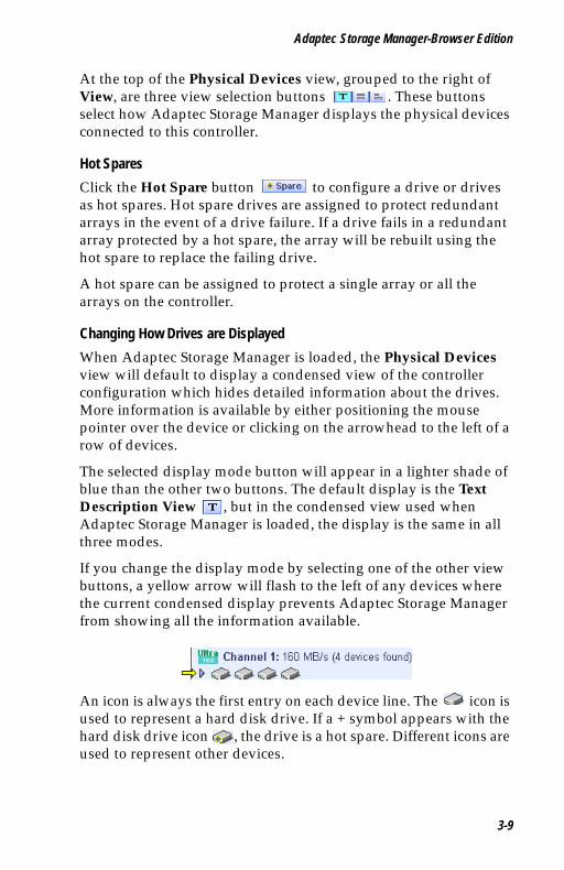
If you change the display mode by selecting one of the other view buttons, a yellow arrow will flash to the left of any devices where the current condensed display prevents Adaptec Storage Manager from showing all the information available.
An icon is always the first entry on each device line. The icon is used to represent a hard disk drive. If a + symbol appears with the hard disk drive icon , the drive is a hot spare. Different icons are used to represent other devices.
3-9
Adaptec SCSI RAID 2120S/2200S Software User’s Guide
UG.book Page 10 Saturday, October 26, 2002 12:08 PM
View
is the default display mode and when expanded, will show the following information about each device:
■ Capacity of the drive
■ Drive manufacturer and model number
■ SCSI drive ID
When expanded, the Full Size Capacity View button and the Relative Size Capacity View button represent each drive as a bar. A drive that is not used as part of any array is shaded blue surrounded by a dotted line.
displays a full-length bar for each drive, regardless of capacity. displays a bar for each drive, with the largest capacity drive
full-length and the other drives proportional to the drive capacity, relative to the largest drive.
Any part of a drive used in an array is shown as a gray segment within the bar. Selecting any gray segment will highlight it in amber and, in the Logical Devices view, highlight the array of which this segment is a member.
In either the Full Size Capacity View or the Relative Size Capacity View, a small portion at the end of the drive is shown in dark gray.
The segment at the end of the drive may vary in size from drive to drive because, in addition to the RAID signature, the controller also limits the usable capacity of each drive to increments of 100 MB.
This is done because hard disk drives of apparently the same capacity from different manufacturers, or even different models from the same manufacturer, actually vary slightly in the true capacity available. Although, in normal operation this is not an issue, it can be when assigning hot spares or replacing a failed drive.
If the controller used the maximum capacity of each drive and a hot spare or replacement drive was just a few megabytes smaller, it would not be able to replace the failed drive. By rounding drive capacities down to the nearest 100 MB, this possibility is effectively eliminated.
3-10
Adaptec Storage Manager-Browser Edition
UG.book Page 11 Saturday, October 26, 2002 12:08 PM
Logical DevicesAs described earlier, when Adaptec Storage Manager loads, the Logical Devices view is expanded and you can see the arrays present on the controller.
At the top of this view are the following buttons: Create, Modify, and Delete. Each button opens a wizard that will take you through, respectively, the steps necessary to create a new array, modify an existing array, and delete existing arrays on this controller.
Modify allows you to:
■ Change an array from one RAID level to another
■ Expand an array
■ Change the stripe size for a RAID-0, 5, 10 or 50
For detailed instructions on using these buttons, see the sections Creating Arrays on page 3-12, Deleting Arrays on page 3-17, and Modifying Arrays on page 3-17.
The main area of the Logical Devices view is used to display the arrays on this controller. It defaults to a condensed view of top level arrays. For information on top and second-level arrays, refer to Supported RAID Types on page 1-2.
Note: The Options button allows you to display second-level arrays if you prefer.
In this condensed view, the RAID level of each device as well as whether it is protected by a hot spare, is visible.
If a global hot spare exists, all arrays that the hot spare is large enough to protect will show as protected.
In the expanded view, the icons for the arrays are arranged vertically and alongside them are the capacity, name and type of array.
Selecting an array by clicking on it will highlight the following in amber:
■ All the drives or segments that form the array in the Physical Devices view.
3-11
Adaptec SCSI RAID 2120S/2200S Software User’s Guide
UG.book Page 12 Saturday, October 26, 2002 12:08 PM
■ Any second-level arrays that form a top-level array in the Logical Devices view.
■ The Events, Properties, and Tasks buttons in the header frame. This indicates that selecting any of these three buttons will bring up an additional window with information and options specific to that array.
Creating ArraysBefore you use Adaptec Storage Manager to create an array, make sure that you understand the different types of arrays supported, as described in Supported RAID Types on page 1-2, and the type of arrays that are most appropriate for your application.
Click Create to open the Create Array wizard. This wizard offers the following options:
■ Create arrays using default settings.
■ Expand the wizard by clicking on Advanced to see additional options and customize settings.
Using the default settings will create an array of the largest possible capacity on the selected drives, use the default cache setting and, if appropriate, the default stripe size.
To create an array using default settings:
1 Open the Create Array wizard by clicking Create for the controller on which you want to create an array.
2 Select the type of array you want to create in Step 1 of 3 in the Create Array wizard. Then click Next to move to Step 2 of 3.
3 Click the drives you want to include in the array. Selected drives will display an amber check mark. When you have completed your selection click Next to move to Step 3.
Note: The check marks will flash until you have selected enough drives to create this type of array.
3-12
Adaptec Storage Manager-Browser Edition
UG.book Page 13 Saturday, October 26, 2002 12:08 PM
4 Now you can accept the default name for the new array or enter one of your choice. The name you choose must be unique, and can be up to 15 standard ASCII characters in length.
5 When you click Finish, the system will create the new array.
Advanced OptionsCreating an array by clicking Advanced in the Create Array wizard follows the same basic process as the previous instructions, but at each step there are additional options for you to use.
Step 1 of 3 in the Advanced area of the Create Array wizard offers the following additional options:
■ Spanned Volumes and RAID Volumes—As described in Chapter 1, Introduction, a spanned volume concatenates segments from two or more drives to form a volume, while a RAID volume concatenates two or more arrays of the same type.
■ Enable or Disable Write Caching—When write caching is enabled, the controller stores the data in cache memory on the controller and will accept another write to this array as soon as the data from the previous write is safely stored in the controller’s memory.
Since writing data to memory is much faster than writing it to the drives, enabling write caching can significantly improve performance. All data stored in the cache will be written to the drives when it is most efficient for the controller.
On controllers fitted with a battery, the additional choice “Enable when protected by battery” is available. Choosing this option will enable write caching whenever the battery is operating correctly, and in the event of a power failure the battery will protect the data currently in cache.
Caution: Default setting for write cache is enabled. This setting provides the best performance, but in the event of power failure there is a risk of data loss.
!
3-13

Adaptec SCSI RAID 2120S/2200S Software User’s Guide
UG.book Page 14 Saturday, October 26, 2002 12:08 PM
■ Enable Or Disable Read Caching—When enabled, the controller will monitor read accesses to this array to try to predict where future reads may occur. If it detects a pattern, the data that seems most likely to be read next will be preloaded into the controller’s cache memory. Since reading data from memory on the controller is much faster than reading it from the drives, this can have a significant impact on performance.
This setting defaults to Enabled.
Step 2 of 3 in the Advanced area of the Create Array wizard offers the following additional options:
■ Limit Array Capacity—This option allows you to choose the capacity of the array you are creating. The default is to make the array the largest possible size with the drives selected. To create multiple arrays on a single set of drives you must use this option to limit the size of, at a minimum, the first array.
For example, if you have two 18 GB drives, and you wish to use them to create two 9 GB RAID-1s, you would use this option to restrict the size of the first array you create.
Note: A RAID-1 uses two drives to create a mirror; that is all data written to a RAID-1 is written to both drives limiting the capacity of the array to the capacity of the smaller drives.
■ Stripe Size—For a RAID-0, 5, 10 or 50 where data is striped across multiple drives, stripe size determines how much data is written on each drive for a given stripe.
Note: The default stripe size has been chosen to maximize performance for most typical applications. Changing the stripe size is likely to adversely affect performance.
3-14
Adaptec Storage Manager-Browser Edition
UG.book Page 15 Saturday, October 26, 2002 12:08 PM
For arrays which need to be initialized such as RAID-1 and RAID-5, advanced options allow you to select which method is used to initialize the array and set the priority of the initialization task.
Step 3 in the Advanced area of the Create Array wizard offers the following initialization options:
■ Build—For a RAID-1, the data from the primary or master drive is copied to the secondary or slave drive. For a RAID-5, correct parity is generated for the entire array.
The advantages of building an array are that the array is immediately available for use, and that when the build is complete, the array operates at maximum performance. The disadvantages are that building takes some time, for a large array possibly many hours, and performance is impacted until the build completes.
■ Clear—In this case, the contents of all the drives are cleared. The advantages of clearing an array are that the process is much faster than building and when completed, the array operates at maximum performance. The disadvantage is that the array is not accessible until the clear completes.
■ Quick—In this case the array is immediately available. The advantage of quick initialization is that the array is immediately available with no on-going build. The disadvantage is that the write performance of a RAID-5 or RAID-50 initialized in this way is impacted until a Verify with fix Task is run on the array.
■ Initialization Priority—This drop-down list allows you to adjust the priority of the initialization task. The default setting is high, and initialization will complete as fast as possible. The other options are medium and low. Depending on what other tasks are running on the controller, selecting either of these options may cause the initialization to take significantly longer.
3-15

Adaptec SCSI RAID 2120S/2200S Software User’s Guide
UG.book Page 16 Saturday, October 26, 2002 12:08 PM
Creating and Deleting Hot Spares
Creating Hot SparesTo create a hot spare:
1 Click on the button on the Physical Devices view.
2 In the Physical Devices view, select the drive(s) you want to make hot spares.
Note: You cannot select a drive that is already used in an array as a hot spare.
3 The advanced option for the Hot Spare button describes how to dedicate a hot spare to protect a single array.
If you wish to dedicate a hot spare to protect a single array, select the array you want the hot spare to protect. If you do not select an array, the hot spare(s) will be global, that is they will protect all the arrays on the controller that they are large enough to protect.
4 Click Finish.
Deleting Hot SparesTo delete a hot spare:
1 Click the Hot Spare button on the Physical Devices view.
2 In the Physical Devices view select the hot spare(s) you wish to delete.
3 Click Finish.
3-16
Adaptec Storage Manager-Browser Edition
UG.book Page 17 Saturday, October 26, 2002 12:08 PM
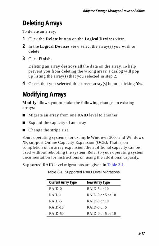
Deleting ArraysTo delete an array:
1 Click the Delete button on the Logical Devices view.
2 In the Logical Devices view select the array(s) you wish to delete.
3 Click Finish.
Deleting an array destroys all the data on the array. To help prevent you from deleting the wrong array, a dialog will pop up listing the array(s) that you selected in step 2.
4 Check that you selected the correct array(s) before clicking Yes.
Modifying ArraysModify allows you to make the following changes to existing arrays:
■ Migrate an array from one RAID level to another
■ Expand the capacity of an array
■ Change the stripe size
Some operating systems, for example Windows 2000 and Windows XP, support Online Capacity Expansion (OCE). That is, on completion of an array expansion, the additional capacity can be used without rebooting the system. Refer to your operating system documentation for instructions on using the additional capacity.
Supported RAID level migrations are given in Table 3-1.
Table 3-1 Supported RAID Level Migrations
Current Array Type New Array Type
RAID-0 RAID-5 or 10
RAID-1 RAID-0 or 5 or 10
RAID-5 RAID-0 or 10
RAID-10 RAID-0 or 5
RAID-50 RAID-0 or 5 or 10
3-17
Adaptec SCSI RAID 2120S/2200S Software User’s Guide
UG.book Page 18 Saturday, October 26, 2002 12:08 PM
The following rules apply to migration:
1 The capacity of the new array must match or exceed the capacity of the current array.
2 If the capacity and/or RAID type of the new array requires greater total drive capacity than the current array, the additional capacity must be on drives that are not already used in the current array.
To modify an array:
1 Click Modify.
2 Select the array that you wish to modify.
3 Select the RAID level that you want to migrate the array to, or if you want to expand the capacity of the existing array, select the current RAID level.
Optionally, click Advanced to select the stripe size you want the new array to use, or that you want to change the existing array to.
4 If necessary, select the additional drive(s) required for capacity expansion, or necessary to support the new RAID level.
Optionally, click Advanced to adjust the priority for the task.
5 Click Finish.
3-18
Adaptec Storage Manager-Browser Edition
UG.book Page 19 Saturday, October 26, 2002 12:08 PM
User Interface OptionsClick Options to modify the behavior of some aspects of the Adaptec Storage Manager user interface. Changes take place immediately when you make a new selection in one of the drop-down lists.
You can make changes in the following areas:
■ Second-Level Arrays—The default is to hide second-level arrays in the Logical Devices view. You can choose to display second-level arrays.
■ Background Update Frequency—This option controls how frequently Adaptec Storage Manager polls the web server to get updated configuration information. The default is 30 seconds. Other choices are 15 seconds, 1 minute, and 5 minutes.
■ Highlight on Mouseover—As you move the cursor around the Adaptec Storage Manager screen, you may notice that an amber box surrounds the controller, channel, device, or array.
This highlight is enabled by default and can be disabled by selecting No in the drop-down list for Highlight on mouseover.
■ Popup Tool Tips—As you move the mouse cursor around the screen, you may notice that if you position the cursor over a device or button a popup tool tip appears. For buttons, the tips contain helpful information about the function of the button, although for devices they display additional information.
Tool tips are enabled by default and appear after a brief delay. You can opt to either disable the tool tips or to have them pop up immediately.
Close the window by clicking the X in the top right corner.
3-19
Adaptec SCSI RAID 2120S/2200S Software User’s Guide
UG.book Page 20 Saturday, October 26, 2002 12:08 PM
Viewing EventsThe Events button allows you to view events for all supported controllers in the system.
The following information is available for each event:
■ the date and time the event occurred
■ the severity of the event
■ a brief message describing the event.
The default is All which displays all levels of event: Critical, Warning and Informational.
A drop-down list is provided that lets you choose to view either critical and warning level events only (Warning), or critical events only (Critical).
At the bottom of the screen is a button to Clear the event log.
HelpClick Help to open a screen with the following tabs: This Application, Technical Support, and Sales.
Click This Application tab to view information about the name and version of the application, as well as a link to the online help.
Click the Technical Support tab for the link to Adaptec’s Technical Support web site.
Click the Sales tab to find telephone numbers and an e-mail address for Adaptec Sales, as well as links to Adaptec’s Online Store and Product Information web sites.
3-20
Adaptec Storage Manager-Browser Edition
UG.book Page 21 Saturday, October 26, 2002 12:08 PM
Displaying and Modifying PropertiesClick Properties to see additional details about many of the components on the Adaptec Storage Manager screen. To see properties about a particular controller, channel, device, or array, select that item before clicking Properties.
If Properties is amber, clicking on it will open a window with further information and options about the item selected. If Properties is blue, clicking on it will display the hostname of the system you are connected to.
Applying ChangesMany property windows allow you to make changes. If you have selected a modifiable field, Apply and Cancel buttons will appear.
Controller PropertiesSelecting a controller, then clicking Properties will bring up a dialog window with the following tabs: General, Alarm, Battery, and Details.
General Tab
Lists the following information about the selected controller:
■ Model—Adaptec model number. This is also displayed on the main screen for each controller.
■ Serial number—A number that uniquely identifies this particular controller.
■ Host bus—The type and the number of the bus to which this controller is connected.
■ Memory size—The total amount of memory installed on the controller.
■ Cache size—Most of the controller’s memory is used as data cache. Cache size is the amount of the controller’s memory used as data cache. Typically, it will be the majority of the memory size indicated above.
■ Number of channels—The number of channels (SCSI or ATA) on this controller.
3-21

Adaptec SCSI RAID 2120S/2200S Software User’s Guide
UG.book Page 22 Saturday, October 26, 2002 12:08 PM
Alarm Tab
Appears for Adaptec RAID controllers equipped with an audible alarm. The following options are available:
■ Disable—Click this button if you want to disable the alarm, that is, if you do not want an audible warning of a problem with this controller. Default is enabled. When Disable is selected it becomes the Enable button.
■ Test—Use this button to test the alarm. You may want to try this to establish if the alarm can be heard clearly in your implementation, or if the volume of the alarm will be too intrusive.
■ Silence—If the alarm is sounding, clicking on this button will silence the alarm without disabling it.
Battery Tab
Appears if the controller is fitted with a battery module. This window lists various components details for this controller:
■ Status—Shows the current status of the battery. A bad battery is one that does not hold charge and should be replaced. Possible values are Failed, No Charge, Charging, Active (drawing power), Unknown.
■ Recalibrate—On some controllers, the battery periodically needs to be run through a process known as recalibration to ensure that it remains fully operational.
For controllers where this button does not appear, recalibration is not required.
If this button is present, then the battery on this controller should be recalibrated every 6 - 12 months.
3-22

Adaptec Storage Manager-Browser Edition
UG.book Page 23 Saturday, October 26, 2002 12:08 PM
Details Tab
This window lists details of some components for this controller:
■ Monitor, Kernel, BIOS versions—These are the version numbers of the different software components loaded on the controller. For some controllers all three components may not be present.
■ Hardware version—The revision level of the controller hardware.
■ Processor type and speed—Information about the processor fitted on the controller. This information is not available on some controllers.
Channel PropertiesSelect a channel and then click Properties to bring up a dialog box with a single tab containing the following information:
■ Type—Indicates whether the selected channel is SCSI, ATA or Serial ATA.
■ Max data rate—The highest rate at which this channel can transfer data, for example, 320 MB/s.
Physical Device PropertiesIf you select a device on a channel (other than an enclosure) and then select Properties, a window with General, Capacity, SMART, and LED tabs will appear.
General Tab
■ Status—This field appears only for disk drives and it indicates the current status of the drive. Possible values are: Optimal, Failed, Phantom (not physically found), SMART Warning, Unknown and Missing.
■ Type—The class of device; for example: disk drive, CD-ROM, scanner, or printer.
■ Product—The name given to this device by its vendor.
■ Vendor—The manufacturer of this device.
3-23
Adaptec SCSI RAID 2120S/2200S Software User’s Guide
UG.book Page 24 Saturday, October 26, 2002 12:08 PM
■ Revision—The version number information stored on the device.
■ Data Rate—The data transfer speed negotiated between the controller and this device.
■ SCSI ID, LUN—For devices on a SCSI channel the SCSI ID and LUN of the device are reported. These do not apply for ATA and Serial ATA devices and will always return 0.
Capacity Tab
The Capacity tab appears only for disk drives and when selected, displays a summary view listing the reserved, used, available, and total capacities of the drive.
The capacities are reported in both the number of 512-byte blocks (shown in both decimal and hexadecimal values) and capacity in kilobytes, megabytes, or gigabytes.
Selecting the detailed option shows information for all segments on the drive. In this view, the following information is displayed for each segment:
■ Number of the segment
■ Start and end blocks
■ Segment size and type
Type indicates how the segment is used. The first and last segments are always reserved. The beginning of the drive is where the controller stores the RAID signature. The end of the drive is where the capacity is rounded down to the nearest 100 MB.
If this segment is a component of an array, type indicates the array level the segment is used in. If the segment is not used in an array, and is not a reserved area, it will be shown as available.
Detailed view defaults to displaying the numbers of the start and end blocks of each segment in decimal values. A drop-down list is provided to allow you to display these numbers in either hexadecimal or capacity.
3-24
Adaptec Storage Manager-Browser Edition
UG.book Page 25 Saturday, October 26, 2002 12:08 PM
SMART Tab
For hard disk drives that support SMART predictive failure reporting, this additional tab will appear with the following entries:
■ Enabled—indicates if SMART reporting is enabled on this device.
■ Predictive failure occurred—indicates if this device has reported a predictive failure.
LED Tab
The tab appears or hard disk drives, and has two buttons, Blink LED and Unblink All.
■ Blink LED—Clicking this button will cause the activity LED of the selected drive to blink. Use this to identify the drive. The activity LED will continue to blink until you click Unblink All.
■ Unblink All—Clicking this button cancels the effect of the Blink LED button for all drives.
Enclosure PropertiesSelecting an enclosure and clicking Properties will open a screen with the following tabs: General, Fans, PSU, Temperature, Devices and Speaker.
General Tab
The General tab includes the following information:
■ Vendor—The manufacturer of the enclosure.
■ Product—The name given to this enclosure by its vendor.
■ Revision—The version number information stored on the enclosure.
■ Status Summary—This provides an overview of the status of the fans, PSU(s) and temperature sensors in the enclosure.
Further detail on each component is available on the relevant tab.
3-25

Adaptec SCSI RAID 2120S/2200S Software User’s Guide
UG.book Page 26 Saturday, October 26, 2002 12:08 PM
Fans and PSU Tabs
The Fans and PSU (Power Supply Units) tabs contain a table listing, by number, all the fans/PSUs in the enclosure and their status.
Temperature Tab
The Temperature tab contains a table listing all of the temperature sensors in the enclosure by number. For each sensor the current temperature and status is displayed.
You can select whether temperatures are displayed in Fahrenheit or Celsius.
Devices Tab
The Devices tab contains a table listing the slots in the enclosure by number. For each slot the SCSI ID of any device present is listed, along with that device’s current status.
Speaker Tab
The Speaker tab indicates whether the enclosure is equipped with a speaker.
For enclosures with a speaker a Silence Alarm button will also be present to allow you to turn off the speaker in the event of a failure.
Logical Device PropertiesSelecting a logical device and clicking Properties will open a screen with the following tabs: Logical Drive and Cache Settings.
Logical Drive Tab
The Logical Drive tab includes the following information:
■ Status—Possible values are optimal, quick init, impacted, degraded, failed, offline.
■ Array name—This is a modifiable field that displays the name assigned to this array at creation. You can click in the array name field and rename the array using any unique combination of up to 15 standard ASCII characters.
■ Type—The RAID level or volume type of the selected array.
3-26
Adaptec Storage Manager-Browser Edition
UG.book Page 27 Saturday, October 26, 2002 12:08 PM
■ Capacity—The physical capacity of the selected array in gigabytes with the number of blocks in parenthesis.
■ Stripe Size—Where applicable, the stripe size of the selected array.
■ Hot spare—Indicates, for redundant arrays, if a hot spare protects the selected array.
■ Logical drive number—A number assigned to the selected array by the controller. This number is only used by the controller.
Note: It is worth noting that if the system is booting from the controller that this array is connected to, the lowest number array (typically array 0) is the boot device. ACU provides an option to select any array and make it the boot device. If you choose to do so, the array you choose to make the boot device will become array 0. This action may result in other array(s) being renumbered.
Cache Settings Tab
The Cache Settings tab duplicates the options presented in the advanced version of the Create Array wizard. You can choose to modify the settings for both read and write cache.
Write cache can be set to disable, enable always, or (if the controller is fitted with a battery) enable when protected.
Read cache can be enabled or disabled.
Viewing and Creating TasksThe Tasks button has a window which contain two tabs: Task Viewer and New Task.
Task Viewer TabDisplays details of current and scheduled tasks for the system or the selected controller, channel, array or drive.
3-27

Adaptec SCSI RAID 2120S/2200S Software User’s Guide
UG.book Page 28 Saturday, October 26, 2002 12:08 PM
It is only possible to create tasks for arrays or drives. If you select Tasks for a channel, controller, or the system, all relevant tasks will be displayed.
When Adaptec Storage Manager is installed a scheduled task is created to perform a weekly background consistency check of all hot spares in the system. This task can be seen by clicking Tasks when it is blue, that is when nothing is selected.
New Tasks TabAllows you to create new tasks for an array or a drive. New Tasks can either be run immediately, or scheduled to run at a later time. Available tasks are Verify, Verify with Fix, and Clear. An explanation of the impact of each task is given below.
■ Drive
■ Verify—Performs a test of the entire drive to ensure that there are no problems. Any bad blocks found are not repaired.
■ Verify with Fix—Performs a test of the entire drive to ensure that there are no problems. Any bad blocks found are repaired.
■ Clear—Erases all data on the drive. Any data previously on the drive is not recoverable, and if all or part of the drive is used in an array, data integrity of the array will be compromised.
■ Array
■ Verify—Performs a test of the entire array to ensure that data is consistent. Any inconsistency found is not repaired.
■ Verify with Fix—Performs a test of the entire array to ensure that data is consistent. Any inconsistency found is repaired.
■ Clear—Erases all data on the array. Any data previously on the array is not recoverable.
3-28
Adaptec Storage Manager-Browser Edition
UG.book Page 29 Saturday, October 26, 2002 12:08 PM
To create a task:
1 Select the array or drive you want the task to run on.
2 Click Tasks.
3 Select the New Tasks tab.
4 Select the type of task from the drop-down list.
5 Select the priority for the task. The default is High.
6 If you want the task to start immediately, click OK. Or, if you want to schedule the task for later, select Schedule.
If you select Schedule, additional options will appear that will allow you to see the day of week and time you want the task to start, as well as the time format. Once you have selected the time and day, click OK.
About Adaptec Storage Manager Notifier ServiceAdaptec Storage Manager - Browser Edition includes a notifier service that enables controller events to be added to the system event log. This service can notify users, through e-mail, of controller events.
When you install Adaptec Storage Manager on a system equipped with an Adaptec Advanced RAID controller, the notifier service is installed and configured to log all events to the system event log. The default installation has email event notification disabled.
Notifier Service Event LevelsAdaptec Advanced RAID controllers support three event levels:
■ Critical
■ Warning
■ Informational
The level(s) of events entered in the system log and received by each user is configured independently.
3-29
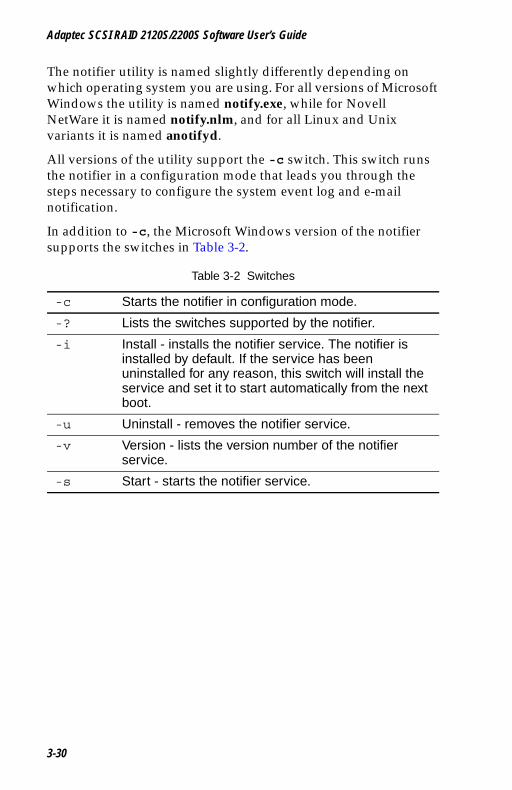
Adaptec SCSI RAID 2120S/2200S Software User’s Guide
UG.book Page 30 Saturday, October 26, 2002 12:08 PM
The notifier utility is named slightly differently depending on which operating system you are using. For all versions of Microsoft Windows the utility is named notify.exe, while for Novell NetWare it is named notify.nlm, and for all Linux and Unix variants it is named anotifyd.
All versions of the utility support the -c switch. This switch runs the notifier in a configuration mode that leads you through the steps necessary to configure the system event log and e-mail notification.
In addition to -c, the Microsoft Windows version of the notifier supports the switches in Table 3-2.
Table 3-2 Switches
-c Starts the notifier in configuration mode.
-? Lists the switches supported by the notifier.
-i Install - installs the notifier service. The notifier is installed by default. If the service has been uninstalled for any reason, this switch will install the service and set it to start automatically from the next boot.
-u Uninstall - removes the notifier service.
-v Version - lists the version number of the notifier service.
-s Start - starts the notifier service.
3-30
Adaptec Storage Manager-Browser Edition
UG.book Page 31 Saturday, October 26, 2002 12:08 PM
Enabling and Configuring the Notifier ServiceBefore you begin to configure e-mail notification you need to have the following information available:
■ The SMTP mail server host name or IP address.
■ The port that SMTP mail server is configured to use. The default value of 25 was chosen because it is the default for most SMTP mail server packages. If you are unsure ask your e-mail administrator.
■ The SMTP e-mail address to which all returned e-mail should be forwarded. SMTP e-mail addresses take the form [email protected].
■ The SMTP e-mail address of all users that need to receive event notifications.
Before you configure the notifier be sure the notifier service and ARCPD are stopped.
Controlling ARCPD for Windows 2000To stop the ARCPD for Windows 2000, right click My Computer > Manage > Service and Applications > then right click Adaptec Web Server > Stop > Yes. This will also stop the Adaptec Storage Manager Notifier.
To restart, repeat the process above for both the Adaptec Web Server and the Adaptec Storage Manager Notifier and click Start instead of Stop.
Controlling ARCPD for Unix and LinuxThe ARCPD starts automatically in both Unix and Linux. To stop the ARCPD, in the /opt/Adaptec/SMBE/etc prompt, type Daemon stop.
To restart, type Daemon restart (as it appears in the list of selections in /opt/Adaptec/SMBE/etc).
3-31
Adaptec SCSI RAID 2120S/2200S Software User’s Guide
UG.book Page 32 Saturday, October 26, 2002 12:08 PM
Controlling ARCPD for NetWareTo stop the ARCPD using NetWare, type unload arcpd.nlm then unload notify.nlm.
To restart the ARCPD, type load arcpd.nlm then load notify.nlm.
Configuring the Notifier Service To configure the notifier service:
1 Place your cursor at a command prompt in the directory where Adaptec Storage Manager was installed.
2 Type any of the following commands:
■ For Windows: notify -c > Enter
■ For Unix/Linux: anotifyd -c > Enter
■ For Netware: load notify -c > Enter
System Event LogThe next step in configuring the notifier utility will ask you whether or not controller events should be added to the system event log. The default is set to log no events.
To add controller events:
1 Choose Y (yes).
2 Select which level(s) of events you want to log. The list of events are found in Table 3-3. Each level of event can be enabled or disabled independently. For example, press 1 to enable logging of Critical events. Alternatively, to log both Critical and Warning, press 1 then 2.
3-32
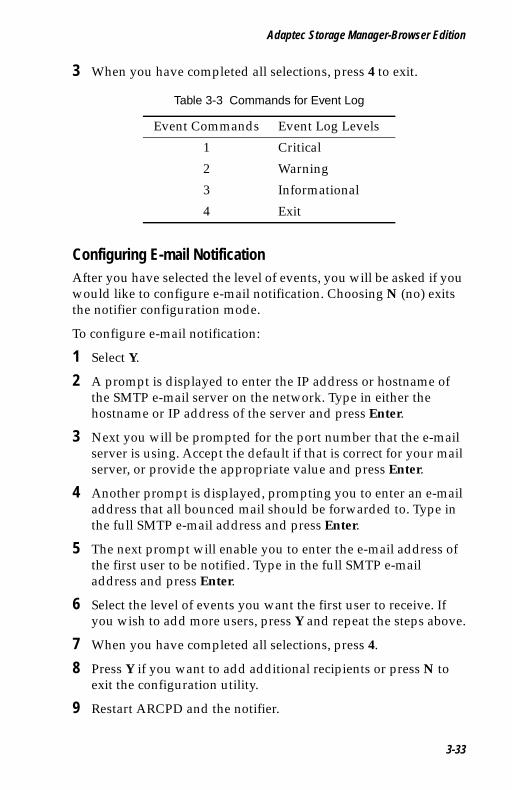
Adaptec Storage Manager-Browser Edition
UG.book Page 33 Saturday, October 26, 2002 12:08 PM
3 When you have completed all selections, press 4 to exit.
Configuring E-mail NotificationAfter you have selected the level of events, you will be asked if you would like to configure e-mail notification. Choosing N (no) exits the notifier configuration mode.
To configure e-mail notification:
1 Select Y.
2 A prompt is displayed to enter the IP address or hostname of the SMTP e-mail server on the network. Type in either the hostname or IP address of the server and press Enter.
3 Next you will be prompted for the port number that the e-mail server is using. Accept the default if that is correct for your mail server, or provide the appropriate value and press Enter.
4 Another prompt is displayed, prompting you to enter an e-mail address that all bounced mail should be forwarded to. Type in the full SMTP e-mail address and press Enter.
5 The next prompt will enable you to enter the e-mail address of the first user to be notified. Type in the full SMTP e-mail address and press Enter.
6 Select the level of events you want the first user to receive. If you wish to add more users, press Y and repeat the steps above.
7 When you have completed all selections, press 4.
8 Press Y if you want to add additional recipients or press N to exit the configuration utility.
9 Restart ARCPD and the notifier.
Table 3-3 Commands for Event Log
Event Commands Event Log Levels
1 Critical
2 Warning
3 Informational
4 Exit
3-33
Adaptec SCSI RAID 2120S/2200S Software User’s Guide
UG.book Page 34 Saturday, October 26, 2002 12:08 PM
Reconfiguring E-mail NotificationTo change the level of events e-mailed to a user, or to stop all messages from being sent to a user, re-run the notifier in configuration mode.
At the system event log prompt, press Y. The configured events you previously selected will be displayed. Press 4 to exit the display. Press Enter at the IP address, port number, and bounced e-mail prompts to leave these prompts unchanged.
Type the e-mail address for the user you wish to remove, delete, or modify. Press Enter.
A prompt asks if you want to delete the selected user. Press Y to remove the user. Press N to modify the level of events the user receives.
3-34

UG.book Page 1 Saturday, October 26, 2002 12:08 PM
4
Using the Command Line InterfaceIn this ChapterIntroducing the Command Line Interface 4-2
Accessing the Command Line Interface 4-2
Terminology 4-3
Using the CLI 4-4
General Control Commands 4-16
Container (Array) Commands 4-18
Controller Commands 4-29
Diagnostic Commands 4-32
Disk Commands 4-34
Logfile Commands 4-38
Task Commands 4-39
Enclosure Commands 4-40
Using Automated Command Scripts 4-44
4-1

Adaptec SCSI RAID 2120S/2200S Software User’s Guide
UG.book Page 2 Saturday, October 26, 2002 12:08 PM
Introducing the Command Line InterfaceTo configure and manage components running on the controller, Adaptec provides an easy-to-use graphical user interface (GUI) called Adaptec Storage Manager as well as a command line interface (CLI).
The CLI provides an alternative to Adaptec Storage Manager. Through the CLI, you can perform most of the storage management tasks that you can perform with Adaptec Storage Manager and, in addition, some tasks not available in the GUI. To automate testing or array creation in a production environment, the CLI enables you to use CLI commands in Windows command scripts and UNIX/Linux shell scripts.
This chapter describes briefly some of the commands available in the CLI. For a full description of all the CLI commands see the Adaptec SCSI RAID Software Reference Guide.
Accessing the Command Line InterfaceYou can execute the command line interface (CLI):
■ From the Windows XP, Windows 2000 or Windows NT Start button
Note: The following procedure assumes that you accepted the default location for the software during installation.
To access the CLI from the Windows XP(basic disk only), Windows 2000(basic disk only) or Windows NT Start button:
1 Click the Start button and move the mouse cursor to Programs. Click on Programs.
2 Move the mouse cursor to SMBE. The Adaptec program group will display.
3 Move the mouse cursor to the CLI icon. Click on CLI.
■ From the NetWare server console
To access the CLI from the NetWare server console, type aaccli at the prompt. When the system displays the CLI> prompt, which indicates that you can now use CLI commands.
4-2
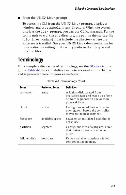
Using the Command Line Interface
UG.book Page 3 Saturday, October 26, 2002 12:08 PM
■ From the UNIX/Linux prompt
To access the CLI from the UNIX/Linux prompt, display a window and type aaccli in any directory. When the system displays the CLI> prompt, you can use CLI commands. For the commands to work in any directory, the path in the startup file (.login or .cshrc) must include the directory where the software is installed. See your UNIX/Linux documentation for information on setting up directory paths in the .login and .cshrc files.
TerminologyFor a complete discussion of terminology, see the Glossary in this guide. Table 4-1 lists and defines some terms used in this chapter and is presented here for your ease-of-use:
Table 4-1 Terminology Chart
Term Preferred Term Definition
container array A logical disk created from available space and made up of one or more segments on one or more physical disks.
chunk stripe Contiguous set of data written to one segment before the controller moves to the next segment.
freespace available space Space on an initialized disk that is not in use.
partition segment Contiguous area of a physical drive that makes up some or all of an array.
failover disk hot spare Drive available to replace a failed component in an array.
4-3
Adaptec SCSI RAID 2120S/2200S Software User’s Guide
UG.book Page 4 Saturday, October 26, 2002 12:08 PM
Using the CLIBrief descriptions of many of the CLI commands are provided later in this chapter.
This section contains some examples of using CLI commands to perform common tasks.
■ Opening and Closing a Controller
■ Creating Single-Level Arrays
■ Deleting Arrays
■ Enabling Spares
■ Displaying Controller Information
■ Displaying Disk Information
■ Displaying Array Information
Opening and Closing a ControllerBefore any command can be sent to a specific controller that controller must first be opened. Only one controller may be open at any time.
To open controller AAC0 use the following command.CLI> open AAC0
When you have finished with the controller close it with the following command.AAC0> close
Creating Single-Level ArraysThis section explains how to create and work with single-level arrays. The RAID software supports four types of single-level containers:
■ Volume
■ RAID 0
■ RAID 1
■ RAID 5
4-4
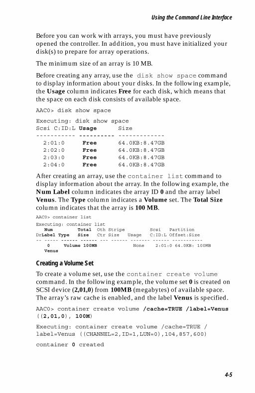
Using the Command Line Interface
UG.book Page 5 Saturday, October 26, 2002 12:08 PM
Before you can work with arrays, you must have previously opened the controller. In addition, you must have initialized your disk(s) to prepare for array operations.
The minimum size of an array is 10 MB.
Before creating any array, use the disk show space command to display information about your disks. In the following example, the Usage column indicates Free for each disk, which means that the space on each disk consists of available space.
AAC0> disk show space
Executing: disk show space Scsi C:ID:L Usage Size----------- ---------- -------------2:01:0 Free 64.0KB:8.47GB2:02:0 Free 64.0KB:8.47GB2:03:0 Free 64.0KB:8.47GB2:04:0 Free 64.0KB:8.47GB
After creating an array, use the container list command to display information about the array. In the following example, the Num Label column indicates the array ID 0 and the array label Venus. The Type column indicates a Volume set. The Total Size column indicates that the array is 100 MB.AAC0> container list
Executing: container list Num Total Oth Stripe Scsi Partition
DrLabel Type Size Ctr Size Usage C:ID:L Offset:Size -- ----- ------ ------ --- ------ ------- ------ -----------
0 Volume 100MB None 2:01:0 64.0KB: 100MB Venus
Creating a Volume Set
To create a volume set, use the container create volume command. In the following example, the volume set 0 is created on SCSI device (2,01,0) from 100MB (megabytes) of available space. The array’s raw cache is enabled, and the label Venus is specified.
AAC0> container create volume /cache=TRUE /label=Venus ((2,01,0), 100M)
Executing: container create volume /cache=TRUE /label=Venus ((CHANNEL=2,ID=1,LUN=0),104,857,600)
container 0 created
4-5

Adaptec SCSI RAID 2120S/2200S Software User’s Guide
UG.book Page 6 Saturday, October 26, 2002 12:08 PM
Creating a RAID 0
When creating a RAID 0, you need to determine the stripe size that is most suitable for your environment. The stripe size attribute indicates the number of bytes in a stripe, the amount of data written to a segment before the I/O data stream switches to the next segment in the stripe. The stripe size can be 16 KB, 32 KB, or 64 KB. The default stripe size is 32 KB. Note that you can use the container reconfigure command at a later time to change the stripe size.
To create a RAID 0, use the container create stripe command. In the following example, the stripe set 0 is created on SCSI device (2,01,0) from 100 MB of available space. The array’s raw cache is enabled, and the label Mars is specified.
AAC0> container create stripe /cache=TRUE /label=Mars ((2,01,0), 100M)
Executing: container create stripe /cache=TRUE /label="Mars" ((CHANNEL=2,ID=1,LUN=0),104,857,600 )
container 0 created
Creating a RAID 1
To create a RAID 1, use the container create new_mirror command. In the following example, a RAID 1 is created on SCSI devices (2,2,0), and (2,3,0) using 100 M of available space from each SCSI device.
AAC0> container create new_mirror ((2,2,0), 100M) (2,3,0)
Executing: container create new_mirror ((CHANNEL=2,ID=2,LUN=0),104,857,600 ) (CHANNEL=2,ID=3,LUN=0)
4-6
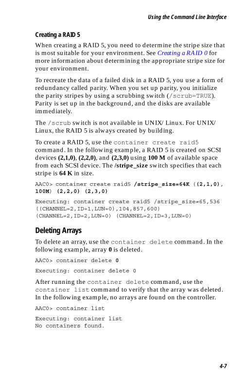
Using the Command Line Interface
UG.book Page 7 Saturday, October 26, 2002 12:08 PM
Creating a RAID 5
When creating a RAID 5, you need to determine the stripe size that is most suitable for your environment. See Creating a RAID 0 for more information about determining the appropriate stripe size for your environment.
To recreate the data of a failed disk in a RAID 5, you use a form of redundancy called parity. When you set up parity, you initialize the parity stripes by using a scrubbing switch (/scrub=TRUE). Parity is set up in the background, and the disks are available immediately.
The /scrub switch is not available in UNIX/Linux. For UNIX/Linux, the RAID 5 is always created by building.
To create a RAID 5, use the container create raid5 command. In the following example, a RAID 5 is created on SCSI devices (2,1,0), (2,2,0), and (2,3,0) using 100 M of available space from each SCSI device. The /stripe_size switch specifies that each stripe is 64 K in size.
AAC0> container create raid5 /stripe_size=64K ((2,1,0), 100M) (2,2,0) (2,3,0)
Executing: container create raid5 /stripe_size=65,536 ((CHANNEL=2,ID=1,LUN=0),104,857,600) (CHANNEL=2,ID=2,LUN=0) (CHANNEL=2,ID=3,LUN=0)
Deleting ArraysTo delete an array, use the container delete command. In the following example, array 0 is deleted.
AAC0> container delete 0
Executing: container delete 0
After running the container delete command, use the container list command to verify that the array was deleted. In the following example, no arrays are found on the controller.
AAC0> container list
Executing: container list No containers found.
4-7
Adaptec SCSI RAID 2120S/2200S Software User’s Guide
UG.book Page 8 Saturday, October 26, 2002 12:08 PM
Enabling SparesA spare disk (also called a “hot spare”) is a disk that you configure to recover data from a failed segment/disk in a redundant array. To assign one or more spare disks for a single array, use the container set failover command. To assign one or more spare disks for all arrays, use the container set global_failover command. The main characteristic of these commands is that you must “manually” assign the spare disk to one or more arrays. In fact, you might consider the previously described spare mechanism as “manually set spare.”
Note: RAID 1, 5 10 and 50 use the spare assignment if a disk fails. (RAID 1, 5, 10 and 50 are often referred to as redundant arrays).
Automatic rebuild on replacement allows you to replace a failed disk with a replacement disk. The controller automatically assigns the disk you insert as a hotspare without your having to first assign it manually using the container set failover or container set global_failover command.
See the Adaptec SCSI RAID Software Reference Guide for more information on the container set failover and container set global_failover commands.
Caution: The controller deletes any data on the replacement disk when automatic rebuild on replacement is enabled and you remove the failed disk and insert the replacement disk in the failed disk’s slot.
Note: The automatic spare feature works only with disks that reside in an SAF-TE or SES enabled enclosure.
Through the CLI, you can:
■ Display a controller’s automatic rebuild on replacement status
■ Enable automatic rebuild on replacement
!
4-8

Using the Command Line Interface
UG.book Page 9 Saturday, October 26, 2002 12:08 PM
To display a controller’s automatic rebuild on replacement status, use the controller show automatic_failover command. In the following example, rebuild on replacement is indicated as DISABLED.
AAC0> controller show automatic_failover
Executing: controller show automatic_failoverAutomatic failover DISABLED
To enable automatic spare, use the controller set automatic_failover command with the /failover switch, as in the following example:
AAC0> controller set automatic_failover /failover_enabled=TRUE
Executing: controller set automatic_failover /failover_enabled=TRUE
After running the controller set automatic_failover command, use the controller show automatic_failover command to verify that automatic rebuild on replacement has been enabled. If necessary, you can now replace a failed disk with a replacement disk.
Displaying Controller InformationControllers exhibit a number of attributes that you can display or manage using the following CLI commands:
■ controller list
Example of controller list:CLI> controller list
Executing: controller listAdapter Name Adapter Type Availability------------ ------------ ------------\\.\AAC0 Adaptec xxxxx read/write
Controller Attribute: Indicates:
controller (adapter) name Name
controller (adapter) type Product name
controller availability Access mode
4-9
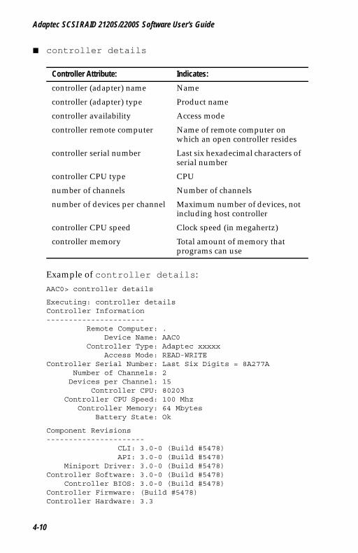
Adaptec SCSI RAID 2120S/2200S Software User’s Guide
UG.book Page 10 Saturday, October 26, 2002 12:08 PM
■ controller details
Example of controller details:AAC0> controller details
Executing: controller details Controller Information----------------------
Remote Computer: .Device Name: AAC0
Controller Type: Adaptec xxxxxAccess Mode: READ-WRITE
Controller Serial Number: Last Six Digits = 8A277ANumber of Channels: 2
Devices per Channel: 15Controller CPU: 80203
Controller CPU Speed: 100 MhzController Memory: 64 Mbytes
Battery State: Ok
Component Revisions----------------------
CLI: 3.0-0 (Build #5478)API: 3.0-0 (Build #5478)
Miniport Driver: 3.0-0 (Build #5478)Controller Software: 3.0-0 (Build #5478)
Controller BIOS: 3.0-0 (Build #5478)Controller Firmware: (Build #5478)Controller Hardware: 3.3
Controller Attribute: Indicates:
controller (adapter) name Name
controller (adapter) type Product name
controller availability Access mode
controller remote computer Name of remote computer on which an open controller resides
controller serial number Last six hexadecimal characters of serial number
controller CPU type CPU
number of channels Number of channels
number of devices per channel Maximum number of devices, not including host controller
controller CPU speed Clock speed (in megahertz)
controller memory Total amount of memory that programs can use
4-10
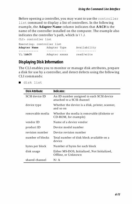
Using the Command Line Interface
UG.book Page 11 Saturday, October 26, 2002 12:08 PM
Before opening a controller, you may want to use the controller list command to display a list of controllers. In the following example, the Adapter Name column indicates that AAC0 is the name of the controller installed on the computer. The example also indicates the controller’s path, which is \\.\ CLI> controller list
Executing: controller listAdapter Name Adapter Type Availability------------ ------------ ------------\\.\AAC0 Adaptec xxxxx read/write
Displaying Disk InformationThe CLI enables you to monitor or manage disk attributes, prepare a disk for use by a controller, and detect defects using the following CLI commands:
■ disk list
Disk Attribute: Indicates:
SCSI device ID An ID number assigned to each SCSI device attached to a SCSI channel
device type Whether the device is a disk, printer, scanner, and so on
removable media Whether the media is removable (diskette or CD-ROM, for example)
vendor ID Name of a device vendor
product ID Device model number
revision number Device revision number
number of blocks Total number of disk block available on a device
bytes per block Number of bytes for each block
disk usage Either MS-DOS, Initialized, Not Initialized, Offline, or Unknown
shared channel N/A
4-11
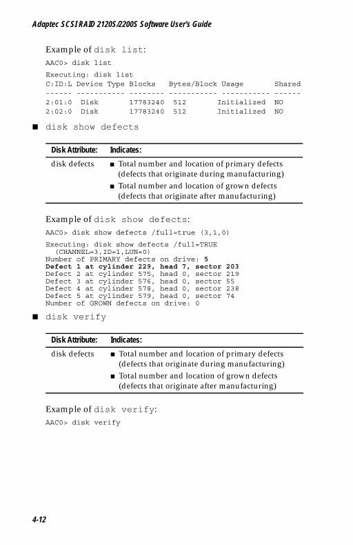
Adaptec SCSI RAID 2120S/2200S Software User’s Guide
UG.book Page 12 Saturday, October 26, 2002 12:08 PM
Example of disk list:AAC0> disk list
Executing: disk listC:ID:L Device Type Blocks Bytes/Block Usage Shared------ ----------- -------- ----------- ----------- ------2:01:0 Disk 17783240 512 Initialized NO2:02:0 Disk 17783240 512 Initialized NO
■ disk show defects
Example of disk show defects:AAC0> disk show defects /full=true (3,1,0)
Executing: disk show defects /full=TRUE (CHANNEL=3,ID=1,LUN=0)
Number of PRIMARY defects on drive: 5Defect 1 at cylinder 229, head 7, sector 203Defect 2 at cylinder 575, head 0, sector 219Defect 3 at cylinder 576, head 0, sector 55Defect 4 at cylinder 578, head 0, sector 238Defect 5 at cylinder 579, head 0, sector 74Number of GROWN defects on drive: 0
■ disk verify
Example of disk verify:AAC0> disk verify
Disk Attribute: Indicates:
disk defects ■ Total number and location of primary defects (defects that originate during manufacturing)
■ Total number and location of grown defects (defects that originate after manufacturing)
Disk Attribute: Indicates:
disk defects ■ Total number and location of primary defects (defects that originate during manufacturing)
■ Total number and location of grown defects (defects that originate after manufacturing)
4-12
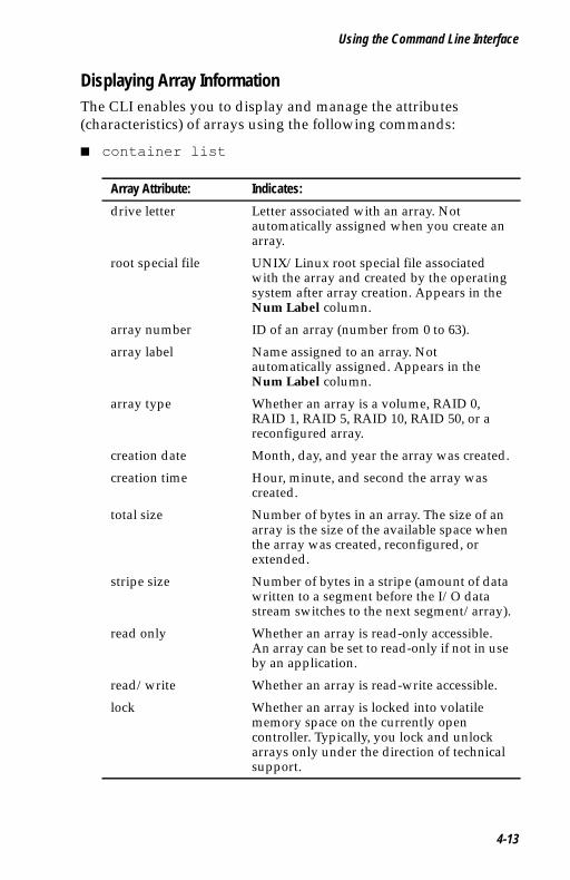
Using the Command Line Interface
UG.book Page 13 Saturday, October 26, 2002 12:08 PM
Displaying Array InformationThe CLI enables you to display and manage the attributes (characteristics) of arrays using the following commands:
■ container list
Array Attribute: Indicates:
drive letter Letter associated with an array. Not automatically assigned when you create an array.
root special file UNIX/Linux root special file associated with the array and created by the operating system after array creation. Appears in the Num Label column.
array number ID of an array (number from 0 to 63).
array label Name assigned to an array. Not automatically assigned. Appears in the Num Label column.
array type Whether an array is a volume, RAID 0, RAID 1, RAID 5, RAID 10, RAID 50, or a reconfigured array.
creation date Month, day, and year the array was created.
creation time Hour, minute, and second the array was created.
total size Number of bytes in an array. The size of an array is the size of the available space when the array was created, reconfigured, or extended.
stripe size Number of bytes in a stripe (amount of data written to a segment before the I/O data stream switches to the next segment/array).
read only Whether an array is read-only accessible. An array can be set to read-only if not in use by an application.
read/write Whether an array is read-write accessible.
lock Whether an array is locked into volatile memory space on the currently open controller. Typically, you lock and unlock arrays only under the direction of technical support.
4-13
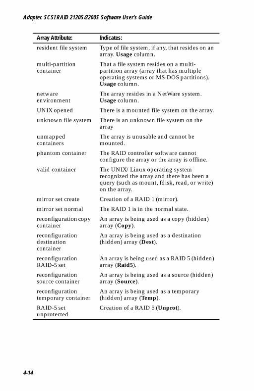
Adaptec SCSI RAID 2120S/2200S Software User’s Guide
UG.book Page 14 Saturday, October 26, 2002 12:08 PM
resident file system Type of file system, if any, that resides on an array. Usage column.
multi-partition container
That a file system resides on a multi-partition array (array that has multiple operating systems or MS-DOS partitions). Usage column.
netware environment
The array resides in a NetWare system. Usage column.
UNIX opened There is a mounted file system on the array.
unknown file system There is an unknown file system on the array
unmapped containers
The array is unusable and cannot be mounted.
phantom container The RAID controller software cannot configure the array or the array is offline.
valid container The UNIX/Linux operating system recognized the array and there has been a query (such as mount, fdisk, read, or write) on the array.
mirror set create Creation of a RAID 1 (mirror).
mirror set normal The RAID 1 is in the normal state.
reconfiguration copy container
An array is being used as a copy (hidden) array (Copy).
reconfiguration destination container
An array is being used as a destination (hidden) array (Dest).
reconfiguration RAID-5 set
An array is being used as a RAID 5 (hidden) array (Raid5).
reconfiguration source container
An array is being used as a source (hidden) array (Source).
reconfiguration temporary container
An array is being used as a temporary (hidden) array (Temp).
RAID-5 set unprotected
Creation of a RAID 5 (Unprot).
Array Attribute: Indicates:
4-14
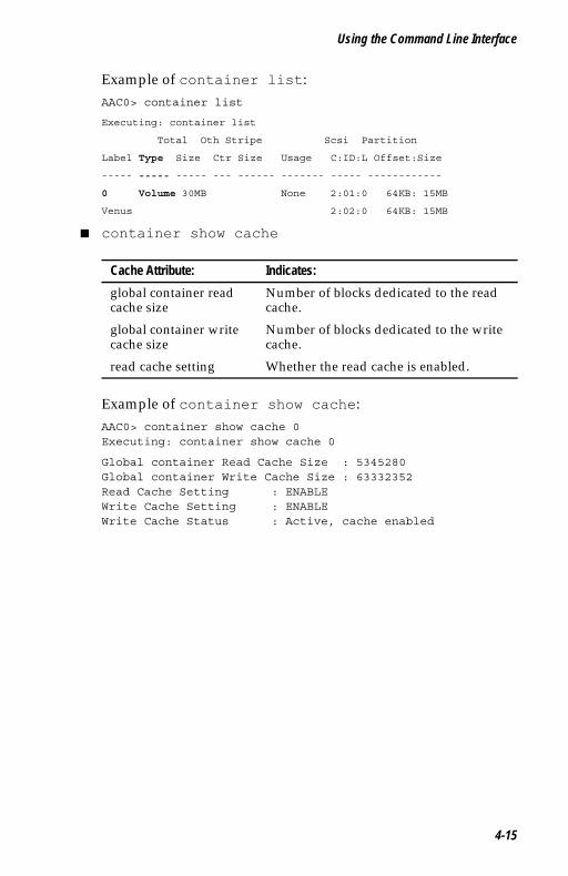
Using the Command Line Interface
UG.book Page 15 Saturday, October 26, 2002 12:08 PM
Example of container list:AAC0> container list
Executing: container list
Total Oth Stripe Scsi Partition
Label Type Size Ctr Size Usage C:ID:L Offset:Size
----- ----- ----- --- ------ ------- ----- ------------
0 Volume 30MB None 2:01:0 64KB: 15MB
Venus 2:02:0 64KB: 15MB
■ container show cache
Example of container show cache:AAC0> container show cache 0Executing: container show cache 0
Global container Read Cache Size : 5345280Global container Write Cache Size : 63332352Read Cache Setting : ENABLEWrite Cache Setting : ENABLEWrite Cache Status : Active, cache enabled
Cache Attribute: Indicates:
global container read cache size
Number of blocks dedicated to the read cache.
global container write cache size
Number of blocks dedicated to the write cache.
read cache setting Whether the read cache is enabled.
4-15
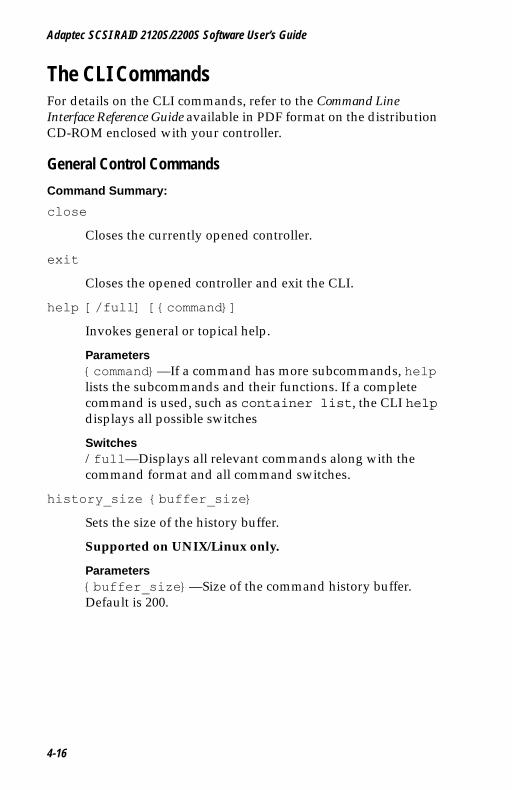
Adaptec SCSI RAID 2120S/2200S Software User’s Guide
UG.book Page 16 Saturday, October 26, 2002 12:08 PM
The CLI CommandsFor details on the CLI commands, refer to the Command Line Interface Reference Guide available in PDF format on the distribution CD-ROM enclosed with your controller.
General Control Commands
Command Summary:
close
Closes the currently opened controller.
exit
Closes the opened controller and exit the CLI.
help [/full] [{command}]
Invokes general or topical help.
Parameters{command}—If a command has more subcommands, help lists the subcommands and their functions. If a complete command is used, such as container list, the CLI help displays all possible switches
Switches/full—Displays all relevant commands along with the command format and all command switches.
history_size {buffer_size}
Sets the size of the history buffer.
Supported on UNIX/Linux only.
Parameters{buffer_size}—Size of the command history buffer. Default is 200.
4-16
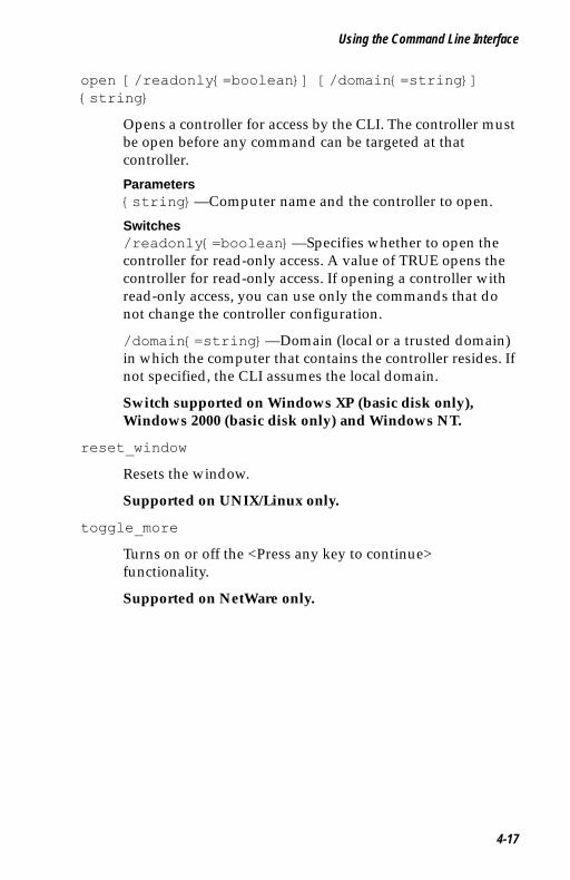
Using the Command Line Interface
UG.book Page 17 Saturday, October 26, 2002 12:08 PM
open [/readonly{=boolean}] [/domain{=string}] {string}
Opens a controller for access by the CLI. The controller must be open before any command can be targeted at that controller.
Parameters{string}—Computer name and the controller to open.
Switches/readonly{=boolean}—Specifies whether to open the controller for read-only access. A value of TRUE opens the controller for read-only access. If opening a controller with read-only access, you can use only the commands that do not change the controller configuration.
/domain{=string}—Domain (local or a trusted domain) in which the computer that contains the controller resides. If not specified, the CLI assumes the local domain.
Switch supported on Windows XP (basic disk only), Windows 2000 (basic disk only) and Windows NT.
reset_window
Resets the window.
Supported on UNIX/Linux only.
toggle_more
Turns on or off the <Press any key to continue> functionality.
Supported on NetWare only.
4-17
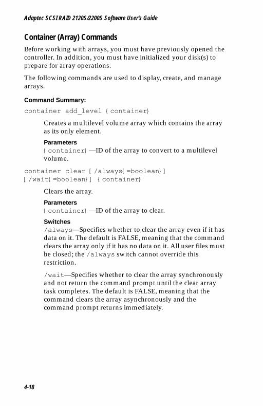
Adaptec SCSI RAID 2120S/2200S Software User’s Guide
UG.book Page 18 Saturday, October 26, 2002 12:08 PM
Container (Array) CommandsBefore working with arrays, you must have previously opened the controller. In addition, you must have initialized your disk(s) to prepare for array operations.
The following commands are used to display, create, and manage arrays.
Command Summary:
container add_level {container}
Creates a multilevel volume array which contains the array as its only element.
Parameters{container}—ID of the array to convert to a multilevel volume.
container clear [/always{=boolean}] [/wait{=boolean}] {container}
Clears the array.
Parameters{container}—ID of the array to clear.
Switches/always—Specifies whether to clear the array even if it has data on it. The default is FALSE, meaning that the command clears the array only if it has no data on it. All user files must be closed; the /always switch cannot override this restriction.
/wait—Specifies whether to clear the array synchronously and not return the command prompt until the clear array task completes. The default is FALSE, meaning that the command clears the array asynchronously and the command prompt returns immediately.
4-18
Using the Command Line Interface
UG.book Page 19 Saturday, October 26, 2002 12:08 PM
container create mirror [wait{=boolean}][/io_delay{=integer}] {container} {scsi_device}
Creates a RAID 1 from a single entry volume.
Parameters{container}—ID of the array on which to create a RAID 1 (mirror).
{scsi_devices}—ID for the SCSI device whose available space to use for mirroring the volume specified in the {container} parameter.
Switches/wait—Specifies synchronous RAID1 creation.
/io_delay—Number of milliseconds between each I/O used for the RAID 1 creation.
container create mmirror [/io_delay{=integer}] [/wait{=boolean}] {container} {scsi_device}[{scsi_device}...]
Creates a multilevel array of RAID 1s from a multilevel array of single entry volumes.
Parameters{container}—ID of the array whose underlying volumes the command converts to RAID 1s.
{scsi_device}—ID for the SCSI device whose available space to use to create the multilevel array of RAID 1s.
{scsi_device}...—IDs for additional SCSI devices whose available space to use to create the multilevel array of RAID 1s.
Switches/io_delay—Number of milliseconds between each I/O used for the RAID 1 create.
/wait—Specifies synchronous RAID 1 creation.
4-19
Adaptec SCSI RAID 2120S/2200S Software User’s Guide
UG.book Page 20 Saturday, October 26, 2002 12:08 PM
container create mstripe [/stripe_size{=integer}] [/label{=string}] {container} [{container}...]
Creates a multilevel RAID 0 (stripe).
Parameters{container}—ID of the array from which to create the multilevel RAID 0.
{container}...—ID(s) of array(s) from which to create the multilevel RAID 0.
Switches/stripe_size—Stripe size for the RAID 0.
/label—Label for the RAID 0.
container create mvolume {container} [{container}...]
Creates a multilevel volume.
Parameters{container}—ID of the array from which to create the multilevel volume.
{container}...—ID(s) of array(s) from which to create the multilevel volume.
Switches/label—Label to assign to the multilevel volume.
4-20
Using the Command Line Interface
UG.book Page 21 Saturday, October 26, 2002 12:08 PM
container create new_mirror [/cache{=boolean}][/clear{=boolean}] [/label{=string}] [</quick_init{=boolean}>] [/scrub{=boolean}] [/wait{=boolean}] {free_space} [{scsi_device}...]
Creates a RAID 1 (mirror) from two available spaces.
container create raid5 [/cache{=boolean}][/stripe_size{=integer}] [/clear{=boolean}] [/label{=string}] [</quick_init{=boolean}>] [/scrub{=boolean}] [/wait{=boolean}] {free_space} [{scsi_device}...]
Creates a RAID 5.
Parameters{free_space}—SCSI device and its associated available space used to create the array.
{scsi_device}...—One or more SCSI devices whose available space to use to create the array.
Switches/cache—Specifies whether to enable the array’s cache.
/stripe_size—Stripe size for the array (only applies to RAID 5).
/clear—Specifies whether to clear the entire array during initialization.
/label—Label to assign to the newly created array.
/quick_init—Specifies to use the Quick Init process, making the array available immediately.
/scrub—Specifies whether to set up the parity by building.
/wait—Specifies whether the command prompt returns only after the parity-protect operation completes.
4-21
Adaptec SCSI RAID 2120S/2200S Software User’s Guide
UG.book Page 22 Saturday, October 26, 2002 12:08 PM
container create stripe [/cache{=boolean}] [/stripe_size{=integer}] [/label{=string}] {free_space} [{scsi_device}...]
Creates a RAID 0 (stripe).
Parameters{free_space}—SCSI device and its associated available space to use to create the RAID 0.
{scsi_devices}...—One or more SCSI devices.
Switches/cache—Specifies whether to enable the array’s raw cache mode.
/stripe_size—Stripe size for the RAID 0. Defaults to 64 KB.
/label—Label to assign to the new RAID 0.
container create volume [/cache{=boolean}] [/label{=string}] {scsi_device}, {free_space}, {scsi_device}, [{free_space}...]
Creates a volume.
Parameters{scsi_device}—SCSI device and its associated available space to use to create the volume.
{free_space}—Available space to use to create the volume.
{scsi_device}, {free_space}...—Additional SCSI devices and associated available spaces.
Switches/cache—Enables the array’s raw array cache.
/label—Label to assign to the new volume.
4-22
Using the Command Line Interface
UG.book Page 23 Saturday, October 26, 2002 12:08 PM
container delete [/always{=boolean}] [/unconditional{=boolean}] {container}
Deletes the array.
Parameters{container}—ID of the array to delete.
Switches/always—Specifies to delete the array even if it has data <a file system>. (Cannot override open files.)
/unconditional—Specifies that the array be deleted even if it has a file system. (Overrides open files.)
container list [/all{=boolean}] [/full{=boolean}] [{container}]
Lists information about the array(s) on the controller.
Parameters{array}—ID of the array containing information to display.
Switches/all—Specifies whether to list all containers on the system.
/full—Specifies whether to display detailed information.
container lock {container}
Locks an array into volatile memory space.
Parameters{array}—ID of the array to lock.
container move {container} {container}
Moves the first array number specified to the second array number specified; in effect, to renumber an array.
Parameters{container}—ID of the array to renumber.
{container}—ID number to assign to the array specified in the first array parameter.
4-23
Adaptec SCSI RAID 2120S/2200S Software User’s Guide
UG.book Page 24 Saturday, October 26, 2002 12:08 PM
container promote {container}
Creates a multilevel volume from a RAID 0 or a single entry volume.
Parameters{container}—ID of the array to promote into a multilevel array.
container readonly {container}
Sets the protection on the array to read-only access.
Parameters{container}—ID of the array to set to read-only access.
container readwrite {container}
Sets the protection on an array to read-write access.
Parameters{container}—ID of the array to set to read-write access.
container reconfigure [/stripe_size{=integer}] [/mirror{=boolean}] [/partition_move{=boolean}] [/partition_size{=integer}] [/raid5{=boolean}] [/raid10{=boolean}] [/restart{=boolean}] [/stripe{=boolean}] [/volume{=boolean}] [/wait{=boolean}] {container} [{scsi_device}...]
Changes the configuration of an array.
Parameters{container}—ID number of the array to reconfigure.
{scsi_device}...—One or more SCSI devices.
Switches/stripe_size—Stripe size of the array.
/mirror—Reconfigure the array into a RAID 1.
/partition_move—Specifies that the array will move partitions instead of add extra space.
/partition_size—Size of a partition.
/raid5—Reconfigure the array into a RAID 5.
4-24
Using the Command Line Interface
UG.book Page 25 Saturday, October 26, 2002 12:08 PM
/raid10—Reconfigure the array into a RAID 10 (stripe of mirrors).
/restart—Restart reconfiguring the array.
/stripe—Reconfigure the array into a RAID 1.
/volume—Reconfigure the array into a volume.
/wait—If specified, waits for reconfiguration to complete before returning.
container release_cache {container}
Releases the controller’s cache buffers.
Parameters{container}—Specifies the ID number of the array on which to release cache buffers.
container remove failover {container} {scsi_device} [{scsi_device}...]
Removes one or more failover disks.
Parameters{container}—ID of the array whose assigned failover disk(s) to remove.
{scsi_device}—ID for the SCSI device to remove as a failover disk(s).
{scsi_device}...—ID(s) for any other SCSI device(s) to remove as a failover disk.
container remove global_failover {scsi_device} [{scsi_device}...]
Removes a global failover assignment.
Parameters{scsi_device}—ID for the SCSI device to remove as a failover disk.
{scsi_device}...—ID(s) for any other SCSI device(s) to remove as a failover disk(s).
4-25
Adaptec SCSI RAID 2120S/2200S Software User’s Guide
UG.book Page 26 Saturday, October 26, 2002 12:08 PM
container restore RAID5 {container}
Tries to restore a RAID 5 that has a number of dead segments as members.
Parameters{container}—ID of the RAID 5 to restore.
container scrub [/io_delay{=integer}] [/no_repair{=boolean}] [/wait{=boolean}] {container}
Checks and repairs the consistency of a redundant array (for example, RAID 5 or mirrors).
Parameters{container}—ID of the redundant array to build.
Switches/io_delay—Number of milliseconds the controller waits between I/Os when building the array.
/no_repair—Specifies whether the build operation be performed without repairing the error.
/wait—Specifies whether the build operation be performed synchronously or asynchronously.
container set cache [/read_cache_enable{=boolean}] [/unprotected{=boolean}] [/write_cache_enable{=boolean}] {container}
Sets cache parameters for a specific array. Useful only if a native operating system's file system resides on the array.
Parameters{container}—Specifies the ID of the array on which to set cache parameters.
Switches/read_cache_enable—Specifies whether to enable the read-ahead cache.
/unprotected—Specifies whether to set the container's NVRAM write-back cache to disable, enable when protected, or enable always. Use this switch in conjunction with the /write_cache_enable switch.
4-26

Using the Command Line Interface
UG.book Page 27 Saturday, October 26, 2002 12:08 PM
/write_cache_enable—Specifies whether to set the container's NVRAM write-back cache to disable, enable when protected, or enable always. Use this switch in conjunction with the /unprotected switch.
container set failover {container} {scsi_device} [{scsi_device}...]
Assigns an automatic failover disk for a single array.
Parameters{container}—ID of the array on which to assign an automatic failover disk(s).
{scsi_device}—ID for the SCSI device to assign as a failover disk.
{scsi_device}...—ID(s) for additional SCSI device(s) to assign as failover disk(s).
container set global_failover {scsi_device} [{scsi_device}...]
Assigns an automatic failover disk for all arrays.
Parameters{scsi_device}—ID for the SCSI device to assign as a failover disk.
{scsi_device}...—ID(s) for additional SCSI device(s) to assign as failover disk(s) to all arrays.
container set io_delay {container} {integer}
Sets the I/O delay (in milliseconds).
Parameters{container}—ID of the array on which to set the I/O delay.
{integer}—Number of milliseconds the controller waits between I/O operations.
4-27

Adaptec SCSI RAID 2120S/2200S Software User’s Guide
UG.book Page 28 Saturday, October 26, 2002 12:08 PM
container set label {container} {string}
Assigns a new label to the array.
Parameters{container}—ID of the array to which to assign a label.
{string}—Specifies the label to assign.
container show cache {container}
Displays caching parameters for an array.
Parameters{container}—ID of the array whose associated cache parameters to display.
container show failover [{container}]
Displays an array’s assigned failover disks.
Parameters{container}—ID of the array whose assigned failover disk(s) to display.
container unlock {container}
Unlocks the array.
Caution: Use only under the direction of Technical Support.
Parameters{container}—ID of the array to unlock.
container unmirror {container}
Changes the RAID 1 (mirror) to a volume and frees the redundant space.
Parameters{container}—ID of the RAID 1 to unmirror.
!
4-28
Using the Command Line Interface
UG.book Page 29 Saturday, October 26, 2002 12:08 PM
Controller CommandsThe following commands are used to display the status of a variety of controller attributes and to perform such tasks as pausing and resuming I/O and enabling or disabling automatic failover.
Command Summary:
controller details
Shows details about the open controller and software.
controller firmware compare [/C{controller_ID}] [{controller_ID}...] [/D{UFI_file_path}]
Compares the contents of each of the flash components on a controller to the corresponding image in user flash image (UFI) files and indicates whether they match.
Switches/C{controller_ID}—ID representing the set of controllers on which to perform the firmware comparison.
/D{UFI_file_path}—Location of the UFI files.
controller firmware save [/C{controller_ID}] [{controller_ID}...] [/D{UFI_file_path}]
Saves the contents of a controller’s flash in user flash image (UFI) files.
Switches/C{controller_ID}—ID representing the set of controllers on which to perform the firmware comparison.
/D{UFI_file_path}—Location of the UFI files.
controller firmware update [/C{controller_ID}] [{controller_ID}...] [/D{UFI_file_path}]
Updates a controller’s flash components from the flash image data in a pair of user flash image (UFI) files.
Switches/C{controller_ID}—ID representing the set of controllers on which to perform the firmware comparison.
/D{UFI_file_path}—Path where the pair of UFI files are located.
4-29
Adaptec SCSI RAID 2120S/2200S Software User’s Guide
UG.book Page 30 Saturday, October 26, 2002 12:08 PM
controller list [/domain{=string}] [{string}]
Lists all controllers or displays information about the currently opened controller.
Parameters{string}—Computer name from which to display a list of controller or specific information about the open controller.
Switches/domain—Specifies the domain in which the host to be searched resides. Supported on Windows XP, Windows 2000 and Windows NT.
controller pause_io [{integer}]
Pauses all I/O activity on the open controller to allow online manipulation of hardware.
Supported on Windows XP (basic disk only), Windows 2000 (basic disk only), Windows NT and NetWare only.
Parameters{integer}—Time in seconds to cause the controller to wait before resuming I/O.
controller rescan
Rescans the SCSI channels and updates all underlying structures.
controller reset_scsi_channel {integer}
Resets a specific SCSI channel on the open controller.
Parameters{integer}—Channel on which to reset this SCSI channel.
controller resume_io
Performs rescan operation and then resumes I/O after pause_io.
4-30
Using the Command Line Interface
UG.book Page 31 Saturday, October 26, 2002 12:08 PM
controller set automatic_failover[/failover_enabled{=boolean}]
Turns on or off automatic failover for the controller.
Switches
/failover_enabled—Specifies whether to turn on or off automatic failover on the controller. Specify 1 to enable, 0 to disable. The default is 0.
controller set container_verify[/verify_enabled{=boolean}]
Turns the container verify task on or off.
Switches/verify_enabled—Specifies whether to turn on or off the container verify feature. The command defaults to TRUE, which means the command turns on the container verify feature.
controller show automatic_failover
Displays the automatic failover status (enabled or disabled) for the controller.
controller show channels
Displays all of the channels on the controller with the characteristics of each channel.
controller show container_verify
Displays the status of the container verify status.
4-31
Adaptec SCSI RAID 2120S/2200S Software User’s Guide
UG.book Page 32 Saturday, October 26, 2002 12:08 PM
Diagnostic CommandsUse the diagnostic commands to provide technical support personnel with information needed to troubleshoot controller problems. Use these commands only under the direction of technical support personnel.
Command Summary:
diagnostic clear boot_parameters
Clears all boot-time parameters.
diagnostic dump structures{string}
Saves internal data structures.
Parameters{string}—Name of the file to contain the internal data structures.
diagnostic dump text
Displays diagnostic information.
diagnostic load_containers
When in maintenance mode, allows arrays to be loaded so they can be verified.
diagnostic moderation set count
Sets the default interrupt count on the controller.
diagnostic moderation set timer {integer}
Sets the default interrupt timer on the controller.
Parameters{integer}—Value to set as the default interrupt timer.
diagnostic moderation show count
Displays the default interrupt count on the controller.
diagnostic moderation show timer
Displays the default interrupt timer on the controller.
4-32
Using the Command Line Interface
UG.book Page 33 Saturday, October 26, 2002 12:08 PM
diagnostic set boot_parameter{string} {integer}
Sets the boot-time parameter.
Parameters{string}—Name of the boot-time parameter.
{integer}—Value for the boot-time parameter.
diagnostic show boot_parameter {string}
Displays the value of the boot-time parameter.
Parameters{string}—Boot-time parameter character string whose associated value you want to display.
diagnostic show history [/old{=boolean}] [/current{=boolean}]
Displays the history buffer contained in the controller’s NVRAM.
Switches/old—Specifies that this command use the controller history buffer from the previous boot.
/current—Specifies that this command use the current controller history buffer (default).
4-33

Adaptec SCSI RAID 2120S/2200S Software User’s Guide
UG.book Page 34 Saturday, October 26, 2002 12:08 PM
Disk CommandsUse the disk commands to manage disks connected to a RAID controller. The CLI enables you to monitor disk characteristics and parameters, prepare a disk for use, and detect defects.
Command Summary:
disk blink {scsi_device} {integer}
Causes the disk access light to blink.
Parameters{scsi_device}—ID of the SCSI device to blink.
{integer}—Number of seconds for the SCSI disk to blink. Zero (0) stops the blinking.
disk initialize [/always{=boolean}] [/unconditional{=boolean}] {scsi_device}
Initializes a SCSI disk on the currently opened controller.
Parameters{scsi_device}—ID of the SCSI device to initialize,
Switches/always—Specifies whether to initialize the disk even if the disk has existing data. (Cannot override open files.) Default is FALSE.
/unconditional—Specifies whether to initialize the disk even if arrays on the disk have open files. Default is FALSE.
disk list [/all{=boolean}] [/full{=boolean}] [{scsi_device}]
Lists the disks available on the controller.
Parameters{scsi_device}—Specifies the ID of the SCSI device to display information.
Switches/all—List of all SCSI devices on the controller.
/full—Detailed information for devices. Default is FALSE.
4-34
Using the Command Line Interface
UG.book Page 35 Saturday, October 26, 2002 12:08 PM
disk remove dead_partitions {scsi_device}
Removes all failed segments from a disk.
Parameters{scsi_device}—ID of the SCSI device from which to remove failed segments.
disk set default {scsi_device}
Sets the default SCSI ID for use in CLI commands.
Parameters{scsi_device}—ID of the SCSI device.
disk set smart [/all{=boolean}] [/clear{=boolean}][/enable_exceptions{=boolean}][/logerr{=boolean}] [/perf{=boolean}] [/report_count{=boolean}] [{scsi_device}]
Changes a disk’s S.M.A.R.T. (Self-Monitoring, Analysis and Reporting Technology) configuration.
Parameters{scsi_device}—ID of the SCSI device on which to change S.M.A.R.T. configurations.
Switches/all—Specifies whether to enable S.M.A.R.T. configurations for all disks.
/clear—Clears the S.M.A.R.T. error counts for the disk.
/enable_exceptions—Specifies whether to enable S.M.A.R.T. exception reporting.
/logerr—Specifies whether to enable logging of S.M.A.R.T. exception reporting.
/perf—Specifies whether to report exceptions according to the MRIE mode.
/report_count—Number of times an exception can be reported. (0 indicates no limit.)
/update—Specifies whether to update the number of device errors found on the specified SCSI device.
4-35
Adaptec SCSI RAID 2120S/2200S Software User’s Guide
UG.book Page 36 Saturday, October 26, 2002 12:08 PM
disk show default
Displays the current default for the SCSI device ID.
disk show defects [/full{=boolean}] {scsi_device}
Shows the number of defects and/or the defect list for a specific disk drive.
Parameters{scsi_device}—ID of the SCSI device.
Switches/full—Specifies whether to display the defect count and the list of defects.
disk show partition
Displays a list of partitions on the disks attached to the currently opened controller.
disk show smart [/all{=boolean}] [/full{=boolean}] [/view_changeable{=boolean}] {scsi_device}
Displays the S.M.A.R.T. configuration information for one or all disks.
Parameters{scsi_device}—ID of the SCSI device for which to display S.M.A.R.T. information.
Switches/all—Specifies whether to display S.M.A.R.T. configurations for all disks.
/full—Specifies whether to display detailed S.M.A.R.T. configuration information for one or all SCSI disks.
/view_changeable—Specifies whether to display the configuration information that can be set on a S.M.A.R.T. disk.
4-36
Using the Command Line Interface
UG.book Page 37 Saturday, October 26, 2002 12:08 PM
disk show space [/all{=boolean}] [{scsi_device}]
Displays space usage information.
Parameters{scsi_device}—ID of the SCSI device for which to display space usage information.
Switches/all—Specifies whether to display all space usage.
disk verify [/repair{=boolean}] [/wait{=boolean}] {scsi_device}
Verifies all blocks on a SCSI device and, optionally, repairs any bad blocks.
Parameters{scsi_device}—Specifies the ID of the SCSI device to verify.
Switches/repair—Specifies whether to automatically repair bad blocks.
/wait—Specifies whether to perform verification synchronously or asynchronously.
disk zero [/repair{=boolean}] [/wait{=boolean}] {scsi_device}
Clears an entire SCSI disk (by writing zeros). All data is erased and cannot be recovered.
Parameters{scsi_device}—ID of the SCSI device to clear.
Switches/always—Specifies whether to clear the disk, even if it has data on it. (Cannot override open files.)
/wait—Specifies whether to clear the disk synchronously or asynchronously. TRUE synchronous and the command prompt does not return until the clear disk task completes.
4-37
Adaptec SCSI RAID 2120S/2200S Software User’s Guide
UG.book Page 38 Saturday, October 26, 2002 12:08 PM
Logfile Commands
Command Summary:
logfile end
Ends logging of all output and closes the log file.
logfile start [/append{=boolean}] {string}
Begins logging of all CLI command line activity to a file.
Parameters{string}—Name of the file to contain to contain CLI command line activity.
Switches/append—Specifies whether to append all CLI command line activity to an existing output file if one exists.
4-38
Using the Command Line Interface
UG.book Page 39 Saturday, October 26, 2002 12:08 PM
Task CommandsUse the CLI commands to display and manage tasks. A task is an operation that occurs only on the controller, asynchronous to all other operations. Examples of tasks are clearing a disk and creating a RAID 1. Once a task is running on the controller, the CLI enables you to display, stop, suspend, and resume the task.
Command Summary:
task list [/all{=boolean}] [{integer}]
Lists the task(s) running on the controller.
Parameters{integer}—Task ID.
Switches/all—Specifies whether to list all currently running tasks.
task resume [/all{=boolean}]
Resumes a task that was suspended or all of the tasks that were suspended.
Parameters{integer}—Task ID for the task to resume.
Switches/all—Specifies whether to resume all suspended tasks.
task stop [/all{=boolean}] [{integer}]
Stops one or all tasks on the controller.
Parameters{integer}—Task ID for the task to stop.
Switches/all—Specifies whether to stop all suspended tasks.
task suspend [/all{=boolean}] [{integer}]
Suspends one or all tasks running on the controller.
Parameters{integer}—Task ID for the task to suspend.
Switches/all—Specifies whether to suspend all running tasks.
4-39
Adaptec SCSI RAID 2120S/2200S Software User’s Guide
UG.book Page 40 Saturday, October 26, 2002 12:08 PM
Enclosure CommandsThe enclosure commands operate on enclosure management devices that support Version 1.0 of the SCSI Accessed Fault-Tolerant Enclosures (SAF-TE) specification. If you are not using an enclosure, the following commands will not be available.
Command Summary:
enclosure activate slot {enclosure} {slot}
Activates a device in a slot in the SAF-TE enclosure.
Parameters{enclosure}—ID associated with the enclosure management device on which to activate a device.
{slot}—Unit number associated with the slot.
enclosure identify slot [/stop{=boolean}] {enclosure} {slot}
Identifies a device in the enclosure.
Parameters{enclosure}—ID associated with the enclosure management device on which to identify a slot.
{slot}—Unit number associated with the slot.
Switches/stop—Specifies whether to stop identifying the slot.
enclosure list [/all{=boolean}] [/full{=boolean}] [{enclosure}]
Lists components for one or all enclosure devices.
Parameters{enclosure}—ID associated with the enclosure management device whose associated components to display.
Switches/all—Lists all enclosures on the system.
/full—Displays detailed component information.
4-40
Using the Command Line Interface
UG.book Page 41 Saturday, October 26, 2002 12:08 PM
enclosure prepare slot {enclosure} {slot}
Prepares a device in a slot for insertion/removal.
Parameters{enclosure}—ID associated with the enclosure management device on which to prepare a slot.
{slot}—Unit number associated with the slot.
enclosure set alarm [/on{=boolean}] {enclosure}
Turns the audible alarm on or off.
Parameters{enclosure}—ID associated with the enclosure management device whose audible alarm to set.
Switches/on—Specifies whether to turn the audible alarm on or off.
enclosure set door [/lock{=boolean}] {enclosure} {door}
Locks or unlocks a specific door on a specific enclosure.
Parameters{enclosure}—ID associated with the enclosure management device on which to lock the door.
{door}—Unit number of the door.
Switches/lock—Specifies whether to lock the door associated with the unit number.
enclosure set fan [/off{=boolean}] {enclosure} {fan} [{speed}]
Sets the speed of a specific fan.
Parameters{enclosure}—ID associated with the enclosure management device on which to set the speed of a fan.
{fan}—Unit number associated with the fan.
{speed}—Speed at which to set the fan.
Switches/off —Specifies whether to turn off the fan.
4-41

Adaptec SCSI RAID 2120S/2200S Software User’s Guide
UG.book Page 42 Saturday, October 26, 2002 12:08 PM
enclosure set interval {second}
Sets the monitor reporting interval (in seconds).
Parameters{second}—Number of seconds for the monitor reporting interval.
enclosure set power {enclosure} {powersupply}
Turns on or off a specific power supply.
Parameters{enclosure}—ID associated with the enclosure management device.
{powersupply}—Unit number associated with the power supply.
Switches/off—Specifies whether to turn on or off the power supply associated with the unit number.
enclosure set scsiid {enclosure} {slot} {device_id}
Sets the SCSI ID of the device slot.
Parameters{enclosure}—ID associated with the enclosure management device.
{slot}—Unit number associated with the device slot to assign a SCSI channel number.
{device_id}—ID of the SCSI device.
enclosure set temperature {enclosure} {degree}
Sets the temperature threshold.
Parameters{enclosure}—ID associated with the enclosure management device on which to set a temperature threshold.
{degree}—Temperature (in degrees Fahrenheit from 0 to 255).
4-42
Using the Command Line Interface
UG.book Page 43 Saturday, October 26, 2002 12:08 PM
enclosure show fan [{enclosure}] [{fan}]
Displays the status of a specific fan.
Parameters{enclosure}—ID associated with the enclosure management device for which to display fan status.
{fan}—Unit number associated with the fan.
enclosure show power [{enclosure}] [{powersupply}]
Displays the status of one or more power supplies.
Parameters{enclosure}—ID associated with the enclosure management device for which to display power supply status.
{powersupply}—Unit number associated with the power supply.
enclosure show slot [{enclosure}] [{slot}]
Displays the status of a specific device slot on a specific enclosure.
Parameters{enclosure}—ID associated with the enclosure management device for which to display device slot status.
{slot}—Unit number associated with the device slot whose status to display.
enclosure show status [{enclosure}]
Displays general status of a specific enclosure.
Parameters{enclosure}—ID associated with the enclosure management device for which to display status.
4-43
Adaptec SCSI RAID 2120S/2200S Software User’s Guide
UG.book Page 44 Saturday, October 26, 2002 12:08 PM
enclosure show temperature [{enclosure}] [{sensor}]
Displays temperature status of a specific enclosure.
Parameters{enclosure}—ID associated with the enclosure management device for which to temperature status.
{slot}—Unit number associated with the temperature sensor whose status to display.
Using Automated Command ScriptsTo execute a CLI command script, type the @ (at sign) followed by the file name that contains the CLI commands, for example:
AAC0>@commandscript.txt
In its simplest form, a CLI command script is a text file that contains valid CLI commands. A carriage return linefeed follows each command. The following CLI command script:
1 Opens controller AAC0 by invoking the CLI command open.
2 Invokes controller details.
3 Closes controller AAC0 by invoking the CLI command close.
4 Exits the example CLI command script.
open AAC0
controller details
close AAC0
exit
4-44
UG.book Page 1 Saturday, October 26, 2002 12:08 PM
A
GlossaryAactivitySee task.
ACU
Array Configuration Utility. An application used to create, configure, and manage arrays from the controller’s BIOS or MS-DOS.
array
A logical disk created from available space and made up of one or more segments on one or more physical disks. Arrays are typically used to provide data redundancy and/or enhanced I/O performance. For more information, see the Adaptec SCSI RAID Software Reference Guide. See also hot spare, segment, volume, RAID 0, RAID 1, RAID 5, RAID 10, RAID 50.
Also known as a container.
array initialization
See initialize.
ATA
AT Bus Attachment. Standard parallel interface to IDE hard disks typically used in desktop computers and some entry-level servers. Serial ATA is a successor to ATA.
automatic failover
See automatic rebuild on replacement
A-1
Glossary
UG.book Page 2 Saturday, October 26, 2002 12:08 PM
automatic rebuild on replacement
In the event of a drive failure in a SAF-TE or SES enclosure attached to a controller with no available hot spares, if rebuild on replacement is enabled then when the failed drive is replaced with a new drive, a rebuild will start automatically.
available space
Unused space on an initialized disk from which logical devices (arrays) are created. When an array is deleted, the space that it used is returned to the available space pool.
Also called available segment.
Bbad segment
Segment that is in an unknown state.
background consistency check
Option that forces the controller to constantly check all portions of disks used by all arrays to see if the disks can return data from the blocks. On a fully-redundant RAID 5 with no dead segments, the controller will repair any data that it cannot read. See also consistency check command.
battery
In the event of a power failure, a battery supplies power to maintain data in the RAID controller’s cache, thereby permitting any dirty data in the cache to be flushed to the drives when power is restored. See also battery reconditioning, dirty data.
battery reconditioning
Periodic discharge/recharge that conditions the battery to attempt to regain lost capacity. Does not apply to all types of battery.
blink
Command that blinks the drive LEDs of all hard disks in a selected array or of a single selected hard disk.
bootable array
Array configured as the boot device.
A-2

Glossary
UG.book Page 3 Saturday, October 26, 2002 12:08 PM
build
Background initialization of a redundant array. The array is accessible throughout. RAID 5 generates parity based on the current contents of the member segments while RAID 1 copies the contents of one (master) drive to a second (slave) drive.
bus
See channel.
Ccache
Fast-access memory on the controller that serves as intermediate storage for data that is read from or written to devices.
capacity
Total usable space available in megabytes or gigabytes.
channel
Any path used for the transfer of data and the control of information between storage devices and a storage controller. Each controller's channels are identified by a number from 0 to the maximum number of channels minus one. Also known as a bus.
chunk
See stripe.
clear
Foreground initialization of a fault-tolerant array. A clear operation zeros all blocks of the array. The array is not accessible until the clear task is complete.
CLI
Command Line Interface. The CLI provides a text-based means of configuring and managing components running on the controller.
concatenation/concatenating
Joining of physical or logical drives in sequential order.
A-3
Glossary
UG.book Page 4 Saturday, October 26, 2002 12:08 PM
consistency check command
Command that reads all the blocks of a RAID 1 or RAID 5 to determine if the blocks are consistent. If any inconsistent blocks are detected, they are fixed.
container
See array. Container is another term for array used in the Adaptec SCSI RAID Software Reference Guide.
Ddead partition
See failed.
dedicated hot spare
Component that can take the place of a failed component only on the fault-tolerant array to which it is explicitly assigned.
degraded
A redundant array in which one or more members have failed such that data is intact but redundancy has been compromised is in the degraded state. The array and all data on it is accessible but a further drive failure would cause the array to fail and result in data loss.
dirty data
Data that has been written to a cache but which has not been “flushed” out to its final destination.
disk
Physical disk drive. Randomly accessible, re-writable data storage device. Also called hard disk.
disk ID
Unique disk identifier that consists of the channel number, SCSI ID (target ID), and LUN. For example, (channel:ID:LUN) 1:04:0. See also channel; LUN; SCSI device ID.
A-4

Glossary
UG.book Page 5 Saturday, October 26, 2002 12:08 PM
drive LED
Disk indicator LED that illuminates during Read or Write operations.
dual-level array
Logical disk created from two or more single-level arrays. See also RAID 10, RAID 50.
Eenclosure
Physical housing for disks, which usually contains one or more power supplies, fans, and temperature sensors. Enclosures are normally external to the computer to which they are connected, although some computers do contain internal enclosures.
enclosure management device
Processor that monitors the fan, power supplies, temperature sensors, and drive presence within a drive enclosure.
event
Notification or alert from the system, indicating that a change has occurred.
event log
File used to maintain information about prior controller activities or errors.
event notification
Means used by the system to communicate information about events that have occurred.
expand
Add space to an array by adding available space.
A-5

Glossary
UG.book Page 6 Saturday, October 26, 2002 12:08 PM
Ffailed
State of a non-redundant array that has suffered a single drive failure, or a a redundant array that has suffered multiple drive failures will be failed and become inaccessible. This will result in data loss.
failed segment
A segment that is no longer usable by an array because it is either logically bad, and therefore no longer needed, or physically damaged.
failover
In a redundant array that has suffered a failure, to automatically reconstruct the missing data onto an assigned hot spare.
fault-tolerant arrays
Refers to an array that can tolerate a disk drive failure without loss or date, and can continue to function. Fault tolerant, or redundant arrays, include RAID 1, 5, 10 and 50 arrays. See also Redundant
first logical device
Device with (virtual) logical device order number 0 (zero). The boot device of the system. Also called first virtual device.
foreign disk
Disk that has previously been initialized on another Adaptec RAID controller. The RAID signature on the disk allows the RAID controller to identify whether the disk was initialized on the controller it is currently connected to or not.
freespace
See available space.
A-6
Glossary
UG.book Page 7 Saturday, October 26, 2002 12:08 PM
Gglobal hot spare
Disk that can replace a failed component in any array on the same controller, provided that the available capacity is at least equal to that of the failed component. See also hot spare.
Hhard disk
See disk.
hot spare
Disk configured to be available to automatically receive reconstructed data in the event of a drive failure in a redundant array. See also rebuild, global hot spare.
hot swap
To remove a component from a system and install a new component while the power is on and the system is running.
Iimpacted
An impacted array is one which has been created but for some reason the initial build operation did not complete. All member drives are present and operational, and all data written to the array is protected. The array can be made optimal by running a Verify with Fix Task on it.
initialize
Process of preparing a disk for use by the controller. When a disk is initialized, the controller records the RAID signature on the disk.
initialized array
An array that is ready for data reads and writes. Arrays can be initialized by build or clear.
A-7
Glossary
UG.book Page 8 Saturday, October 26, 2002 12:08 PM
Llegacy disk
Disk that contained a valid partition table when connected to the controller. The controller manages the disk as a legacy disk array where there is a one-to-one logical to physical mapping of array to disk.
logical device
Device (disk) comprised of spaces from one or more physical drives and presented to the operating system as if it were one drive.
logical device order
Sequence in which the system’s operating system detects the arrays, single hard disks, and other devices connected to the controller when the server boots.
low-level format
Process performed by the drive firmware that completely cleans any data off the hard disk.
LUN
Logical Unit Number. The number assigned to a subdevice of a SCSI device. Each SCSI device can contain up to eight subdevices numbered 0 through 7. However, most SCSI devices contain only one subdevice (LUN 0).
Mmigration
See reconfiguration.
mirror set
See RAID 1.
mirroring; mirrored array
See RAID 1.
A-8
Glossary
UG.book Page 9 Saturday, October 26, 2002 12:08 PM
monitoring
Process of receiving, displaying, and logging system events.
multilevel array
See dual-level array.
OOCE
Online Capacity Expansion. The incremental expansion of an array that requires no downtime and retains all the attributes of the original array. See also reconfiguration, RAID 0, RAID 5.
offline array
Array that can no longer be accessed.
offset
Distance from the beginning of a disk to the start of a segment.
optimal
An array in its normal operational state in which all of the components are present and operating correctly is optimal. For redundant arrays, the entire array is protected.
Pparity
Form of error-checking redundancy used to protect the data in a RAID 5.
partition
See segment.
phantom object
Object that represents a component that cannot be configured by the controller management software; for example, a missing drive.
physical drive
Single drive. See also logical device.
A-9
Glossary
UG.book Page 10 Saturday, October 26, 2002 12:08 PM
Qquick init
An array initialized using the Quick Init option is available immediately, with no on-going background controller activity. All data written to an array that has been quick initialized is protected. An array created using this option will remain in a Quick Init state, and for RAID 5 and 50 write performance will be degraded, until a verify with fix is run on the array.
RRAID
Redundant Array of Independent Disks (alternative definition Redundant Array of Inexpensive Disks). Redundancy, however, is not a feature of RAID 0.
RAID 0
Single-level array consisting of two or more equal-sized segments residing on different disks. RAID 0 distributes, or stripes, data evenly across its respective drives in equal-sized sections. See also single-level array.
Also known as a stripe set.
RAID 0/1
See RAID 10.
RAID 1
Single-level array consisting of two equal segments residing on two different disks. Provides redundancy by storing the same data on two components.
Also known as a mirror set.
RAID 5
Single-level array consisting of at least three equal-sized segments with the capacity of one segment used for parity data. In a RAID 5, parity is distributed in stripes across all segments.
A-10
Glossary
UG.book Page 11 Saturday, October 26, 2002 12:08 PM
RAID 10
Dual-level array created by using two or more equal-sized RAID 1s to create a RAID 0. See also stripe, stripe set.
RAID 50
Dual-level array created by using two or more equal-sized RAID 5s. See also RAID 0, stripe, stripe size.
RAID signature
The area on each disk reserved for use by the RAID controller.
RAID volume
Concatenation of multiple RAID 0, RAID 1, or RAID 5 arrays.
rebuild
Background regeneration of redundant data (and/or parity) on a RAID 1, 5, 10 or 50.
reconfiguration
Process of expanding an array or migrating an array from one RAID type to another; changing the stripe size of a RAID 0, RAID 5, RAID 10 or RAID 50 or moving a logical device’s segments to other disks.
redundant
The ability of an array to maintain operability when one or more hardware failures occur. RAID 1, 5, 10 and 50 are redundant. In the event of a drive failure redundant arrays can be restored to normal operation by replacing the failed drive and rebuilding the array.
rescan
Process of updating the current screen to show all currently available resources.
SSAF-TE
SCSI Accessed Fault-Tolerant Enclosure. See enclosure.
A-11
Glossary
UG.book Page 12 Saturday, October 26, 2002 12:08 PM
SCSI
Small Computer System Interface. High-speed parallel communication scheme permitting data transfer rates of up to 320 MB/sec using the Ultra320 specification. The current specification supports up to 15 devices per channel. See also ATA.
SCSI device ID
Or SCSI ID. Number assigned to each SCSI device attached to a SCSI channel. Also known as target ID.
second-level array
Logical device (lower array in a dual-level array) that is never visible to the operating system and can be used only by other logical devices. For example, a RAID 1 that is a member of a RAID 10 is a second-level array. Contrast with visible array and top-level array.
segment
Reserved area on a physical disk that is a by-product of array creation or failover operation. That is, when the software creates an array, it automatically converts the user-specified available space into segments. A segment is always part of a logical device and cannot be used by more than one logical device at a time.
serial ATA
A successor to ATA that transfers data across a serial interface, instead of a parallel one.
simple volume
Single segment of a drive’s available space.
single-level array
Array created from one or more segments. See also volume, RAID 0, RAID 1, RAID 5.
S.M.A.R.T.
Self-Monitoring Analysis and Reporting Technology. This technology is a drive feature designed to determine the reliability status of a disk. If S.M.A.R.T. senses that a potential problem is imminent, the user may be notified and advised of the appropriate action.
A-12

Glossary
UG.book Page 13 Saturday, October 26, 2002 12:08 PM
snapshot
Instantaneous read-only copy of an array at a precise point in time.
spanned volume
Concatenation of segments on two or more drives.
spare
See hot spare.
stripe
Contiguous set of data distributed across all the disks in an array. A stripe set distributes, or stripes, data evenly across its respective disks in equal sized sections called stripes.
stripe size
In striped array types, (RAID 0, RAID 5, RAID 10, RAID 50) data is distributed, or striped, across the member disks in equally-sized sections. The amount of data in each section on a disk is the stripe size.
stripe set
See RAID 0.
stripe set of mirror sets
See RAID 10.
stripe set of RAID 5
See RAID 50.
Ttask
An operation that occurs only on the RAID controller, asynchronous to all other operations; for example, initializing a disk or verifying an array. Some tasks can take an extended period of time, particularly if the RAID controller is also performing intensive data I/O while the task is running.
A-13
Glossary
UG.book Page 14 Saturday, October 26, 2002 12:08 PM
top-level array
Upper array in a dual-level array. For example, the RAID 0 in a RAID 10 is a top-level array.
Vverify
Low-level check that a drive, logical device, or hot spare is good. In a RAID 5, verify is a low-level check that data and parity is consistent and logs errors and, optionally, corrects errors in parity. In a RAID 1, verify is a low-level check that contents of both members segments are consistent and, optionally, corrects errors while assuming that the master drive is correct. For a drive (and hot spare) verify performs a low-level check that the whole drive can be read.
virtual device order
See logical device order.
visible array
Array (logical device) that is visible to the operating system and to users. Also know as top-level array. Contrast with second-level array.
volume
See simple volume, spanned volume, RAID volume.
volume set of mirror sets
See RAID volume.
volume set of RAID 5
See RAID volume.
volume set of stripe sets
See RAID volume.
A-14

Glossary
UG.book Page 15 Saturday, October 26, 2002 12:08 PM
Wwarning threshold temperature
User-specified temperature limit above which Adaptec Storage Manager - Browser Edition displays a warning in the Enclosure view windows, the Enclosure Properties dialog box, and the Enclosure Fans, Temperature Sensors and Power Supplies dialog box.
A-15

Glossary
UG.book Page 16 Saturday, October 26, 2002 12:08 PM
A-16

UG.book Page 1 Saturday, October 26, 2002 12:08 PM

R
Adaptec, Inc.691 South Milpitas BoulevardMilpitas, CA 95035 USA
© 2002 Adaptec, Inc.All rights reserved. Adaptec and the Adaptec logo are trademarks of Adaptec, Inc. which may beregistered in some jurisdictions.
Stock Number: 513218-06, Ver. AA CLM 10/02
UG.book Page 2 Saturday, October 26, 2002 12:08 PM


