24
How analysis & optimization help meet the time constraints in F1 Simon Gardner | Head of Structures
| Date post: | 13-Aug-2015 |
| Category: |
Technology |
| Upload: | altair |
| View: | 36 times |
| Download: | 1 times |

How analysis & optimization help meet the time constraints in F1 Simon Gardner | Head of Structures

Overall Jordan GP - started with 50 staff in 1991 4 race wins and 3rd in the constructor’s championship Sahara Force India formula One Team Ltd - October 2007 Dr VJijay Mallya and the Mol Family with Sahara joining in 2010 2 podiums, briefly 2nd 2014. Now increased to around 380 staff Aerodynamics 120 staff down at the Wind tunnel 70 design & aero 50 manufacturing Design Office 260 staff at the Head Office 90 Engineers (Various) 90 manufacturing 60 traveling
Background – Force India
Sahara Force India Formula One Team

MAHPP power unit MAMG gearbox SFIF1 is a chassis supplier
Chassis Bodywork (Aerodynamics surfaces) Suspension Braking Steering
Sahara Force India Formula One Team
Background – Force India

Sahara Force India Formula One Team
Aerodynamic / Tyres / Vehicle dynamic Design and structural
Meet design and production intent Running strength Safety requirement Regulation Technical Directives (TDs)
Production R&D testing (sometimes!) Testing/Racing
Design Process

Sahara Force India Formula One Team
Aerodynamics
Restrictions: TFLOPS + wind-on time = 25

Aerodynamic Mass Stiffness (tyres and
handling) Strength Time scales Cost
Design Considerations

Testing History Experience Hand calculations FEA
Method of achieving these targets
Sahara Force India Formula One Team
Analysis Optimisation

Partnership with Sahara Force India Formula One Team
Multiple load cases Complex geometries Complex lay up
Optimisation
Sahara Force India Formula One Team
Topological optimisation Composite optimisation

Sahara Force India Formula One Team
TOPOLOGICAL

Multiple load cases and defined volume Stiffness and strength limited
Typical Topological optimsation
Sahara Force India Formula One Team
>70mm
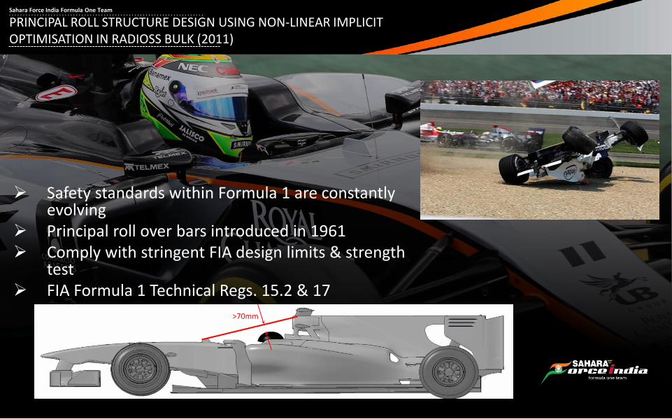
PRINCIPAL ROLL STRUCTURE DESIGN USING NON-LINEAR IMPLICIT OPTIMISATION IN RADIOSS BULK (2011)
Sahara Force India Formula One Team
Safety standards within Formula 1 are constantly evolving
Principal roll over bars introduced in 1961 Comply with stringent FIA design limits & strength
test FIA Formula 1 Technical Regs. 15.2 & 17

Fx = ±60kN
Fz = -90kN
Fy = 50kN
Topological
Sahara Force India Formula One Team
1. Linear topology optimisation 2. Manual iteration non-linear analysis

Objective: minimise mass
LINEAR TOPOLOGY OPTIMISATION
Manufacturing & symmetry constraints Linear stress limit in design domain
~75% MASS REMOVED
Initial design domain Element density CAD realisation of topology result
Sahara Force India Formula One Team

Sahara Force India Formula One Team
Composite (Free size optimisation)

Sahara Force India Formula One Team
Composites offer huge flexibility for designing optimised components Possible design considerations
Material (stiffness and/or strength) Ply orientation angle Patch position Number of plies in a given orientation Ply stacking sequence
Laminating orthotropic layers makes it possible to tune stiffness & strength into required regions
Lightweight core materials can be used to improve bending performance Using traditional analysis methods, it is very difficult to obtain an optimum
design – too many variables and very time consuming
Overview of Composite Design

HyperMesh Optimisation Set up
HyperMesh Modify ply shapes
OptiStruct Free Size Optimisation
HyperView Post Processing
OptiStruct Stack Sequence
Optimisation
HyperView Post Processing
OptiStruct Size Optimisation
HyperView Post Processing
Optimisation Process Summary
Sahara Force India Formula One Team

A front wing typical generates ~30% of an F1 cars total downforce
Stiffness can be tailored
Comply with stringent FIA deflection limits FIA Formula 1 Technical reg. 3.17.1
The objective of this study was to design a new front wing main plane for the 2008 VJM1 which exceeded the structural performance of it’s predecessor
~6kN total force typically generated
Must be lightweight
Sahara Force India Formula One Team
Composite Optimisation of a Formula One Front Wing (2009)

The front wing must withstand both aerodynamic loading conditions as well as standard FIA Formula1 Technical Regulations:
Regulation Details
3.17.1 (2009)
The outer most part of the wing may deflect no more than 10mm when a 500N load is applied vertically, loaded symmetrically.
3.17.1 (2014)
The outer most part of the wing may deflect no more than 10mm when a 1000N load is applied vertically, loaded asymmetrically.
F1 Front Wing Design Requirements
Sahara Force India Formula One Team

Altair Optistruct was used to aid design of the 2008 front wing Ply boundaries & efficient material orientations identified Discrete number of plies Optimised stacking sequence achieved
The final design met all criteria (within a highly compressed time frame)
The final design was able to: Meet both the internal and FIA regulation displacements Improve min. reserve factors Minimise mass Meet manufacturing constraints
This method can be applied across the board for all composite components on the car
Sahara Force India Formula One Team

The design of the rear wing is critical to the performance of an F1 car
The design must withstand large down forces generated by air flow at high speed
All components must be lightweight but satisfy the strength & stiffness requirements: Structurally sound Satisfy FIA regulations
To meet these requirements the rear wing can be constructed from the following layers: Multiple unidirectional layers Cloth layers Lightweight core
The objective of this study was limited to optimising the composite plies in the rear wing end plate and the pillar
Introduction
Optimisation of a Composite Aerodynamic F1 Rear Wing (2008)
Sahara Force India Formula One Team

The rear wing must withstand both aerodynamic loading conditions as well as standard FIA 2008 Formula1 Technical Regulations:
Regulation Details
3.17.3 Bodywork may deflect by no more than one degree horizontally when a load of 1000N is applied to its extremities in a rearward direction
3.17.5 The uppermost aerofoil element may deflect no more than 5mm when a 500N load is applied horizontally
3.17.6 The forward-most aerofoil element lying behind the rear wheel centre line may deflect no more than 2mm when a 200N load is applied vertically
3.17.7 Bodywork may deflect no more than 2mm vertically when a 500N load is applied simultaneously to each side
F1 Rear Wing Design Requirements
Sahara Force India Formula One Team

Mass in design regions reduced by 15%
Reserve factor under aerodynamic loading improved by 7%
Met required FIA regulations
Results Summary
Sahara Force India Formula One Team

In conclusion Formula 1 is a fast paced industry requiring quick and accurate solutions
Sahara Force India Formula One Team
Altair Hyperworks provides: Efficient meshing and analysis tools Optimisation
The optimisation techniques typically used are:
Topological Composite

Sahara Force India Formula One Team
Sahara Force India Formula One
Dadford Road
Silverstone
Northamptonshire
NN12 8TJ
United Kingdom
Simon Gardner
Head of Structures


