74
UK Biomass Carbon Calculator User manual for the Solid and Gaseous Biomass Carbon Calculator Version 1.3 October 2011

UK Biomass Carbon
Calculator
User manual for the Solid and Gaseous Biomass Carbon
Calculator
Version 1.3
October 2011

UK Solid and Gaseous Biomass Carbon Calculator – User manual v1.3 i
Contents
FOREWORD ................................................................................................................................... 1
1 GETTING STARTED ..................................................................................................... 2
1.1 Introduction................................................................................................................................. 2
1.2 Information on calculation methodology and reporting requirements ......... 3
1.3 General information screen ................................................................................................. 4
1.3.1 Saving company information ................................................................................................. 5
1.3.2 Protecting files with passwords............................................................................................. 5
1.4 Adding new years and months ........................................................................................... 6
1.4.1 Adding a new year ..................................................................................................................... 6
1.4.2 Adding a new month ................................................................................................................. 7
2 ADDING A NEW FUEL CHAIN .............................................................................. 9
2.1 Loading a default fuel chain and adding actual data .............................................. 9
2.2 Adding or removing modules from an existing fuel chain .................................. 11
2.3 Constructing a completely new fuel chain ................................................................. 13
3 ENTERING ACTUAL DATA .................................................................................... 17
3.1 Entering values ........................................................................................................................ 17
3.2 Co-product treatment rules ............................................................................................... 18
3.2.1 General rules.............................................................................................................................. 18
3.2.2 Co-products from anaerobic digestion ............................................................................. 19
3.3 Compulsory linkages ............................................................................................................. 22
3.4 Conservative factor for processing steps ................................................................... 23
3.5 Land use change emission calculations ....................................................................... 24
3.6 Entering links to verification evidence ......................................................................... 26
4 INTERPRETING THE RESULTS ......................................................................... 27
4.1 Module results .......................................................................................................................... 27
4.2 Fuel chain results .................................................................................................................... 27
5 PREPARING REPORTS ............................................................................................ 29
5.1 Module reports (pdf format) ............................................................................................. 29
5.2 Project reports (pdf format) ............................................................................................. 31
5.3 Annual reports (xls format) ............................................................................................... 33
6 UPDATES TO SOFTWARE AND DEFAULT VALUES ............................. 36

UK Solid and Gaseous Biomass Carbon Calculator – User manual v1.3 ii
7 MODULE DESCRIPTIONS ..................................................................................... 37
7.1 Units used in the UK Solid and Gaseous Biomass Carbon Calculator ............ 37
7.2 Fuel chain – Electricity ......................................................................................................... 37
7.3 Fuel chain – Heat .................................................................................................................... 39
7.4 Fuel chain – Gas....................................................................................................................... 41
7.5 Crop production ....................................................................................................................... 43
7.6 Harvesting, extraction and roadside processing ..................................................... 47
7.7 Drying and storage ................................................................................................................. 48
7.8 Feedstock transport ............................................................................................................... 50
7.9 Gas transport ............................................................................................................................ 52
7.10 Biomass processing (chipping, briquetting, pelleting) ........................................ 53
7.11 Conversion of biomass feedstock to biogas .............................................................. 56
7.12 Biogas upgrading .................................................................................................................... 59
7.13 Electricity production ............................................................................................................ 61
7.14 Heat production ....................................................................................................................... 63
7.15 Gas injection to the national natural gas grid .......................................................... 64
8 GLOSSARY ....................................................................................................................... 67
8.1 Feedstock types ....................................................................................................................... 67
8.2 Biomass forms .......................................................................................................................... 69
8.3 Process types ............................................................................................................................ 71

UK Solid and Gaseous Biomass Carbon Calculator – User manual v1.3 1
Foreword
This document is the User Manual for version 1.1 of the UK Solid and
Gaseous Biomass Carbon Calculator for operators generating
electricity, heat and biomethane for grid injection from biomass.
The UK Solid and Gaseous Biomass Carbon Calculator contains a
series of UK-defined default values for a large number of solid and
gaseous biomass supply chains to electricity, heat and biomethane
generators in the UK. This calculator should only be used for the
“actual value” method for calculating the carbon intensity of
electricity from biomass.
Furthermore, it is possible to amend these default supply chains
using actual data or to calculate the carbon intensity of electricity,
heat and biomethane based on entirely new chains created by the
user. The Calculator also offers additional functionality such as
showing how the total calculated emissions are split between the
different supply-chain steps, helping to indicate where further cost-
effective GHG reductions might be made. Finally, it is also possible to
prepare summary reports that should help electricity generators in
preparing their submission to Ofgem and for internal records.
Generators who want to use the “default value” method for the
calculating carbon intensity of their biomass electricity, should not
use this Calculator, but instead refer to Ofgem‟s guidance on
sustainability criteria for solid and gaseous biomass. The Ofgem
guidance includes details of the alternative „default value‟ calculation
process and the EU default values for certain whole biomass
pathways as set out in the Renewables Obligation Order.

UK Solid and Gaseous Biomass Carbon Calculator – User manual v1.3 2
1 Getting started
1.1 Introduction
The UK Solid and Gaseous Biomass Carbon Calculator software is
designed to help companies calculate the carbon intensity of the
electricity, heat or biomethane produced from solid biomass and
supplied to the UK grid under the Renewable Obligation Order. It can
also produce annual reporting tables, which should help electricity
generators report the carbon intensity of their electricity to Ofgem on
an annual basis.
The primary aim of the software is to facilitate the use of actual data
collected directly from the supply chain.
The information required for calculating the carbon intensity of a
consignment of fuel is entered using a graphical representation of a
biomass to energy supply chain.
These graphical supply chains are made up of a set of pre-defined
modules which contain all of the data needed to assess the GHG
emissions from this step of the chain.
If several types of fuels are used during a monthly reporting period,
a supply chain should be added for every consignment of fuel about
which you want to assess the carbon intensity.
A single UK Solid and Gaseous Biomass Carbon Calculator project file
can be used to calculate the carbon intensity of fuels used in different
months and years. If that is the case, you will see the list of months
and years included in the project file on the left hand side panel. If
you click on a month, the supply chains that were imported to that
month are then visible on the main fuel chain screen, as in the
screenshot below.

UK Solid and Gaseous Biomass Carbon Calculator – User manual v1.3 3
Version 1.1 of the UK Solid and Gaseous Biomass Carbon Calculator
contains the UK-defined default values for solid and gaseous biomass
chains that can be used for electricity, heat and biomethane injection
to the national grid. Please note that carbon intensity reporting is
only mandatory for electricity – the inclusion of heat and biomethane
injection in the tool is for information purposes only.
1.2 Information on calculation methodology and reporting
requirements
The UK Solid and Gaseous Biomass Carbon Calculator implements
the life cycle calculation methodology set out in the Renewables
Obligation Order and in the Guidance on Solid and Gaseous Biomass
Sustainability Requirements from Ofgem. Furthermore, consistency
with EC-calculated biofuels and bioliquids default values has been
ensured through:
the use of the conservative factor for the processing step (see
Section 3.4)
the use of the same emission factors1 and standard values2
whenever possible
1 Emission factors refer to the life cycle GHG emissions associated with the production
and transport of products and energy carriers that enter into the production of solid and
gaseous biomass.

UK Solid and Gaseous Biomass Carbon Calculator – User manual v1.3 4
Two examples of waste feedstocks (MSW and waste wood) are
included in the UK Solid and Gaseous Biomass Carbon Calculator for
illustrative purposes; it provides information on potential
opportunities for further reductions in GHG emissions in the
particular case of these waste-to-energy chains. It should be noted
that, consistently with the EC life cycle methodology, the UK Solid
and Gaseous Biomass Carbon Calculator does not include avoided
methane emissions, which can for some waste-to-energy supply-
chains reduce the GHG emissions to below zero.
Report creation functions have also been included in the UK Solid and
Gaseous Biomass Carbon Calculator. They are available for all energy
types (i.e. electricity, heat and grid injection), although reporting on
carbon intensity is only required for electricity generated from solid
and gaseous biomass. The following report creation functions are
available in the UK Solid and Gaseous Biomass Carbon Calculator:
Project reports containing information on the fuels used, their
characteristics (feedstock type, feedstock country of origin,
previous land use and the carbon intensity), and an overview of
the actual data input to the chains.
Module report that provide an overview of all the data used in a
module.
Annual reports, which are designed to allow direct submission to
Ofgem. Please note that these reports contain more information
than the minimum Ofgem requirements.
1.3 General information screen
The first screen you see when you open the UK Solid and Gaseous
Biomass Carbon Calculator is the General information screen. Generic
information about the company you are calculating the carbon
intensities for can be entered here. Most of the fields on this page are
optional. The only piece of information that must be provided in order
to continue to the next page is the Energy type.
Note: you can return to this screen at any time by clicking on
„General information‟ at the top of the left hand panel.
Key information which can be entered on this screen includes:
2 Standard values refer to data that reflect some characteristics of the products and
energy carriers that enter into the production of solid and gaseous biomass, such as
their lower heating value, density, etc.

UK Solid and Gaseous Biomass Carbon Calculator – User manual v1.3 5
Project name – a short description of the information can be
entered in this file.
Project description – can include more detailed information
relating to this file (e.g. the scope of biomass types covered,
whether the file is current or no longer being used etc.).
Default fuel type used – select the type of biomass which you are
likely to use most often within the software (you will still be able
to assess the carbon intensity of other fuels).
Default country of origin – select the country from which most of
your biomass feedstock comes (e.g., the United Kingdom) or, if
you receive feedstock from a wide range of countries or regions,
select „Unknown‟.
Energy type – you must choose whether you want to calculate
the carbon intensity of electricity, heat or biomethane for grid
injection, as this will influence the information you will need to
provide to the tool.
Company data – general contact details (you can save this data
and reload it in other files by clicking the „Save company data‟
button).
1.3.1 Saving company information
You may save the company information provided in the General
information screen by clicking „Save company data‟. The data will
then automatically appear every time you open the UK Solid and
Gaseous Biomass Carbon Calculator. Please note that you can only
save one set of company information at a time.
1.3.2 Protecting files with passwords
An individual file can be protected with a password, by enabling this
option within the General information screen. The following steps will
enable password protection of a file. This will mean that anyone who
tries to open this file will be forced to enter the password you specify
before they can view or change any of the information within it. It
also means that the file itself is compressed and encrypted so it
cannot be read by any other software.
Step 1 Click on „General information‟ in the left hand panel.
Step 2 Click on the button „Protect this file with a password‟.
Step 3 Select „Protect this project with a password‟.

UK Solid and Gaseous Biomass Carbon Calculator – User manual v1.3 6
Step 4 Enter the same password twice (the format of the password is up to
you) and click „OK‟.
1.4 Adding new years and months
1.4.1 Adding a new year
An individual file can be used to calculate carbon intensities of fuels
used in different months and years.
It is important to use the correct year and month because the default
values used are linked to the date of the report and may changed in
the future. For example, the default crop yield for wheat might be
6.60 tonnes per hectare for year 2011, but for next year this may
have been updated to 7 tonnes per hectare. Both default values
would in such case be retained within the software so that if you
want to check your results from 2011 they are exactly the same as
when you calculated them (e.g., 6.60 t/ha for wheat). However, if
you unintentionally calculated the carbon intensity of a fuel in year
2011 in the software but for submission in 2012, the software may
use the wrong default values.
To add a new year, follow the steps below.
Step 1 Click the „Create a new year‟ button on the toolbar OR select „New year‟
from the File menu OR right click on the left hand panel and select „New
year‟.
OR

UK Solid and Gaseous Biomass Carbon Calculator – User manual v1.3 7
OR
Step 2 Select the year for which you would like to calculate carbon intensities.
Step 3 Enter a description for the year if you require it.
Step 4 Select the first month for which you would like to calculate the carbon
intensities within this year and click the „Create‟ button.
1.4.2 Adding a new month
To add a new month within an existing year, follow the steps below.
Step 1 Ensure you have the year in which you would like to add a new month
selected, then click the „Create a new month‟ button on the toolbar OR
select „New month‟ from the File menu OR right click on the left hand
panel and select „New month‟.
OR
OR

UK Solid and Gaseous Biomass Carbon Calculator – User manual v1.3 8
Step 2 Select the month for which you would like to calculate carbon intensities
and click the „Create‟ button.

UK Solid and Gaseous Biomass Carbon Calculator – User manual v1.3 9
2 Adding a new fuel chain
The information required to calculate the carbon intensity of a new
type of biomass is entered using a graphical representation of a
biomass supply chain.
These graphical fuel chains are made up of a set of pre-defined
modules which contain all of the data needed to assess the GHG
emissions from this step of the chain. When the tool is used for
reporting purposes, a chain must be added for every consignment of
biomass reported to Ofgem.
These chains can be expanded and/or reduced by clicking on the „+‟ /
„-‟ sign as detailed below.
On the right side of a module in the Calculator, you can see a small
square containing either the sign „-‟ or „+‟, as is shown on the picture
below.
The „-‟ sign means that the chain is expanded – i.e. you can see all
the modules contained in the chain after the specific module.
The „+‟ sign means that the chain is reduced – i.e. you cannot see
any modules after the specific module. However these modules have
not been deleted – they will reappear if you click on the „+‟ – they
have been condensed into one single module.
2.1 Loading a default fuel chain and adding actual data
When loading a default fuel chain, the approach should be to start
from one of the default fuel chains already included in the UK Solid
and Gaseous Biomass Carbon Calculator database.

UK Solid and Gaseous Biomass Carbon Calculator – User manual v1.3 10
To import such a chain, follow the steps below.
Step 1 Click the „import default fuel chain‟ button on the toolbar
Step 2 Select the form of biomass used in the power plant (e.g., charcoal, wood
pellets, straw bales, etc)3, the type of feedstock from which that biomass
form has been produced, (e.g., forestry residues, wheat, sugar cane,
etc.), the type of process (e.g., natural drying, bulk drying, continuous
drying) and the country/region of origin. Then click „Load‟.
If you cannot select the combination of fuel type, feedstock, and
drying process that you require, it is because there is no default
fuel chain currently defined for this supply chain. If this is the
case, it is possible to create a new fuel chain from scratch (see
section 2.3).
If the structure of the default fuel chain for the combination you
have selected does not represent your chain, it is possible to load
a similar fuel chain and then adapt it using the different elements
at the top of the tool bar (see section 2.2).
A list of definitions of the terms used in the fuel chains is available
by clicking „Definitions‟. 4
3 If you are calculating the carbon intensity of biomethane for injection to the national
grid, you will only have one choice of feedstock form, i.e. biomethane.
4 The definitions spreadsheet also indicates whether feedstock types are considered to be
wastes or residues [W/R] or co-products [C].

UK Solid and Gaseous Biomass Carbon Calculator – User manual v1.3 11
Step 3 Select the relevant module and enter the actual data for this supply
chain. See Section 3 for more details on entering actual data.
2.2 Adding or removing modules from an existing fuel chain
In some situations you may wish to add or remove a module from an
existing fuel chain, for example:
A default fuel chain might only include one module for feedstock
transport (e.g., by truck); however, your fuel chain might involve
two transport steps: firstly a short distance by truck, then a
longer distance by rail.
A default fuel chain might include a drying step that is not
required in your fuel chain, and therefore needs to be removed.
The following steps present how to add or remove a module from an
existing fuel chain.
Step 1 Click the „import default fuel chain‟ button on the toolbar.
Step 2 Select the form of biomass used, the feedstock from which the biomass
has been produced, the type of drying process and the country/region
of origin. Then click „Load‟.
If you want to delete a module:
Step 3 Select the module you want to delete by clicking on it once. Delete it
either by using the „Delete‟ key on your keyboard OR by right clicking
on the module and selecting „Delete selected modules‟. Click „yes‟ when
asked if you really want to delete the selected elements.

UK Solid and Gaseous Biomass Carbon Calculator – User manual v1.3 12
Step 4 The fuel chain will now be broken – i.e. there will be two modules which
are not connected by a small black arrow. You can reconnect these two
modules in two ways:
by clicking on the small X (the „connector‟) in the middle of the right
hand side of the first module and, holding the mouse button down,
drag the arrow to the connector on the second module to which you
wish to connect.
by selecting the two modules you wish to connect, right clicking on
one of the modules and selecting the options “Link the 2 selected
modules”.
The connector will have an arrowhead if it is correctly formed. If no
arrowhead appears, it is either because you have not dragged the line
precisely to the connector on the second module, or because these two
types of module are not allowed to connect (see Table in Section 2.3 for
connection rules) – check that the fuel chain you are building is
accurate and permitted.
Correct:
Incorrect:
Step 5 Check all downstream modules, particularly those of the same type to
ensure that the default values provided are still representative of your
chain. For example, transport modes and distances, countries in which
conversion steps take place, etc.
If you want to add a new module:
Step 3 Create some space for the new module (e.g., by selecting and dragging
to the right the modules which will be on the right of the new module).
Step 4 Delete the arrow which connects the two modules in between which you
wish to insert a new module.

UK Solid and Gaseous Biomass Carbon Calculator – User manual v1.3 13
Step 5 On the toolbar, click once on the type of module you wish to add to the
fuel chain (e.g., „Feedstock transport‟) then click the main screen where
you want the new module to appear.
Step 6 Connect the new module to the remaining parts of the fuel chain. You
can connect two modules in several ways:
by clicking the small X (the „connector‟) on the right hand side of
the first module and, holding the mouse button down, dragging the
arrow to the connector on the second module to which you wish to
connect.
by selecting the two modules you wish to connect, right clicking on
one of the modules and selecting the options “Link the 2 selected
modules”.
The line will have an arrowhead if it is correctly formed. If no
arrowhead appears, it is either because you have not dragged the line
precisely to the connector on the second module, or because these two
types of module are not allowed to connect (see Table in Section 2.3 for
connection rules) – check that the fuel chain you are drawing is
accurate.
Correct:
Incorrect:
Step 7 Enter the actual data you have for this module.
Step 8 Check all downstream modules, particularly those of the same type to
ensure that the default values provided are still representative of your
chain. For example, transport modes and distances, countries in which
conversion steps take place, etc.
2.3 Constructing a completely new fuel chain
The software can be used to construct an entirely new fuel chain
(e.g., for a new type of biomass), although it is almost always easier
to edit an existing default fuel chain. This is because most of the data
in the fuel chain would need to be provided from actual data sources,
rather than default values (emissions factors for fertilisers, fuels,
electricity and chemicals are some exceptions).
There are some rules which must be followed when adding
completely new fuel chains:

UK Solid and Gaseous Biomass Carbon Calculator – User manual v1.3 14
Each fuel chain must start with the „Fuel Chain – Electricity‟, „Fuel
Chain – Heat‟ or „Fuel Chain – Gas‟ Module. For a new type of
biomass not included in the Calculator, “other” should be selected
for feedstock type and/or form in the fuel chain module.
The modules must be mapped, from left to right in the same
sequence as the different processing steps occur – e.g., starting
with “crop production”, followed by “harvesting, extraction and
roadside processing”, then feedstock transport, etc.
All modules must be connected with a small black arrow. If these
arrows are not present, the software will not be able to calculate
the carbon intensity of the fuel chain.
It is not possible to have two parallel streams in a fuel chain, you
could, however, represent this situation with two separate fuel
chains.
Incorrect:
Correct:
Not all modules can be connected to each other. This ensures
simple errors cannot be made when building new fuel chains. The
table below indicates which modules can be connected – when
the module in column 1 is the first of two modules (i.e. the first in
a sequence when reading from left to right) it can be connected
to all of the modules listed in column 2.
First module… …can be connected to these modules
Fuel chain –
Electricity
Crop production, Harvesting, Drying and storage, Feedstock
transport, Biomass processing, Biomass processing to gas, Power plant
Fuel chain – Heat Crop production, Harvesting, Drying and storage, Feedstock transport, Biomass processing, Biomass processing to gas,

UK Solid and Gaseous Biomass Carbon Calculator – User manual v1.3 15
Power plant
Fuel chain – Gas Crop production, Harvesting, Feedstock transport, Biomass processing, Biomass processing to gas
Crop production Harvesting, Drying and storage, Feedstock transport, Biomass processing, Biomass processing to gas, Power plant
Harvesting Drying and storage, Feedstock transport, Biomass processing, Biomass processing to gas, Power Plant
Drying and storage
Feedstock transport, Biomass processing, Biomass processing to gas, Power plant
Feedstock transport
Drying and storage, Feedstock transport, Biomass processing, Biomass processing to gas, Power plant
Gas transport Gas transport, Gas processing, Grid injection, Power plant
Biomass
processing
Drying and storage, Feedstock transport, Biomass
processing, Biomass processing to gas, Power plant
Biomass
processing to gas
Gas processing, Gas transport, Grid injection, Power plant
Gas processing Gas processing, Gas transport, Grid injection, Power plant
Grid injection
Power Plant
To add a new module to the screen, follow the steps below.
Step 1 On the toolbar, click once on the type of module you wish to add to the
fuel chain (e.g., „Feedstock transport‟).
Step 2 Click the main screen where you want the new module to appear.
To connect two modules, follow the steps below.
Step 1 Click the small X (the „connector‟) on the right hand side of the first
module and, holding the mouse button down, drag the arrow to the
connector on the second module to which you wish to connect.
OR
Select the two modules you wish to connect, right click on one of the
modules and select the options “Link the 2 selected modules”.
Step 2 Check to see that the line you have added has an arrowhead. If no
arrowhead appears it is either because you have not dragged the line
precisely to the connector on the second module (try Step 1 again) or
because you have tried to connect two modules which not allowed to be
connected (see Table above) – check that the fuel chain you are
drawing up is accurate.
Correct:

UK Solid and Gaseous Biomass Carbon Calculator – User manual v1.3 16
Incorrect:
Step 3 Once you have defined the whole fuel chain, you can begin entering
actual data – see Section 3.

UK Solid and Gaseous Biomass Carbon Calculator – User manual v1.3 17
3 Entering actual data
3.1 Entering values
Once you have loaded a fuel chain (see Section 2) you can begin
entering actual data. See Section 7 for descriptions of the fields in
each module.
In addition to the simple steps below, please also refer to the
information given in Sections 3.2 to 3.5.
Step 1 Double click on the module in which you want to enter actual data.
Step 2 Click the field in which you want to enter actual data.
Step 3 Replace the default value with your actual data (changing the units, if
appropriate, by selecting the new units from the units drop down box).
Step 4 Enter any other actual data for this module and then click „Close‟ to
return to the main fuel chain screen.
Points to note about entering actual data:
Tables of data such as the fertiliser inputs, fuel inputs, chemical
inputs, etc. can be edited using the same process as outlined
above. However, if you wish to add or delete a row, you will need
to use the buttons which appear above the table (the green plus
symbol adds a new row, and the red cross deletes the selected
row).
If a warning symbol appears after you have entered some actual
data, hover the mouse over it to see the warning message. The
message may say „The input you have provided is different from
the default value by more than xx%. Please check that your value
is correct‟ (where xx is a number), which is an indication that the
value you have entered is smaller or larger than what might
normally be expected. This does not lead to any program error –
i.e. the program will still perform the usual calculations. However,
you may want to double check the value entered is correct.
The message may also say „please also provide actual data for
[name of another field]‟ – this is known as a compulsory linkage,
see Section 3.2 for further details.
You can reset a field to the default value by right clicking on the
field and selecting „Reset to default value‟. If you want to reset a
table to its original default value, use the circular arrow button
above the table. Note that you can only reset the whole table, not

UK Solid and Gaseous Biomass Carbon Calculator – User manual v1.3 18
an individual row. You can reset all data in a module by clicking
on the „Reset‟ button which appears at the bottom of each
module.
Actual data stored in a module is shown in bold text.
3.2 Co-product treatment rules
3.2.1 General rules
The Commission Report on sustainability requirements for the use of
solid and gaseous biomass sources in electricity, heating and cooling,
and the Renewable Obligation Order set out the life cycle GHG
emission calculation methodology that should be followed when
assessing the GHG emissions of electricity and heat under the ROO.
This methodology defines, among other rules, how to allocate
emissions when a process is producing several co-products. The
allocation method depends on the type of co-products and is set out
in the following paragraphs. For more information, please refer to the
documents above and to the Ofgem guidance on solid and gaseous
biomass for electricity production.
If one of the co-products is useful heat, then the emissions should be
allocated between the different products by taking into account the
energy content of all the co-products and the temperature of the
useful heat based on the following formula:
Where: Ai = Allocated GHG emissions at allocation point to co-
product, i
E = Total GHG emissions up to allocation point
ηi = The fraction of co-product, measured in energy
content, defined as the annual amount of co-
product produced divided by the annual energy
input
ηh = The fraction of heat produced together with other
co-products, defined as the annual useful heat
output divided by the annual energy input
Ci = Fraction of exergy in the energy carrier (else than
heat), equal to 1
Ch = Carnot efficiency (fraction of exergy in the useful
heat)
The Carnot efficiency, Ch, is calculated as follows:

UK Solid and Gaseous Biomass Carbon Calculator – User manual v1.3 19
Where: Th = temperature of the useful heat, measures in Kelvin
at point of delivery
T0 = Temperature of surroundings, set at 273 Kelvin.
For Th < 150°C, Ch is set to 0.3546.
If none of the co-products are useful heat, the emissions up to the
point of allocation should be divided between the co-products based
on their respective energy content, as shown in the following
formula.
Where: Ai = Allocated GHG emissions at allocation point to co-
product i
E = Total GHG emissions up to allocation point
ηi = The fraction of co-product i, measured in energy
content, defined as the annual amount of co-
product i produced divided by the annual product
input measured in energy content
ηj = The fraction co-product j, measured in energy
content, defined as the annual amount of co-
product j produced divided by the annual product
input measured in energy content
3.2.2 Co-products from anaerobic digestion
When biogas is produced by anaerobic digestion (AD), part of the
biogas is usually burned in a local CHP plant to produce the heat and
electricity required in the biogas production process. Usually the CHP
unit produces more electricity than needed by the system, and thus
some electricity is exported back to the grid. The following
paragraphs explain how to calculate the carbon intensity of the final
biogas, when some of the biogas is used to power the production
process itself.
There are two ways of visualising this process, as represented below.

UK Solid and Gaseous Biomass Carbon Calculator – User manual v1.3 20
This first figure shows the biogas production plant as a black-box,
from which exit both biogas and electricity. In this view, there is no
heat co-produced; the only co-product is electricity. Following the
ROO, upstream GHG emissions should then be allocated between
biogas and electricity based on their energy contents.
However the process could also be visualised as follows:
In this second figure, the biogas production plant is deconstructed
into 2 modules:
one pure AD biogas production module which produces 2 streams
of biogas: biogas-A which exits the anaerobic digestion module
and is transferred to a power-plant and biogas-B which is used in
the local CHP for heat and electricity production; and
one local CHP module which produces the heat used in the AD
biogas production module and some electricity from biogas-A.
In this case, the AD unit has two co-products: biogas-A and biogas-B
and two energy inputs: heat and electricity from the biogas CHP unit.
In terms of co-product treatment, upstream GHG emissions should
be allocated between biogas-A and biogas-B on an energy content
basis and the heat and electricity inputs should be taken into account
through the use of their emission factors.
The default values included in the UK Solid and Gaseous Biomass
Carbon Calculator are calculated based on the first approach set out
above (i.e. biogas production = black box). The treatment of the co-
products is thus to allocate emissions between biogas and electricity
on an energy content basis.
However, for generators who want to calculate their actual carbon
intensity based on the second approach, the steps to follow have
been laid out below.
UK Solid and Gaseous Biomass Carbon Calculator – User manual v1.3 21
Step 1 Build or load a biogas chain.
Step 2 Open the Biogas production plant module, by double clicking on it.
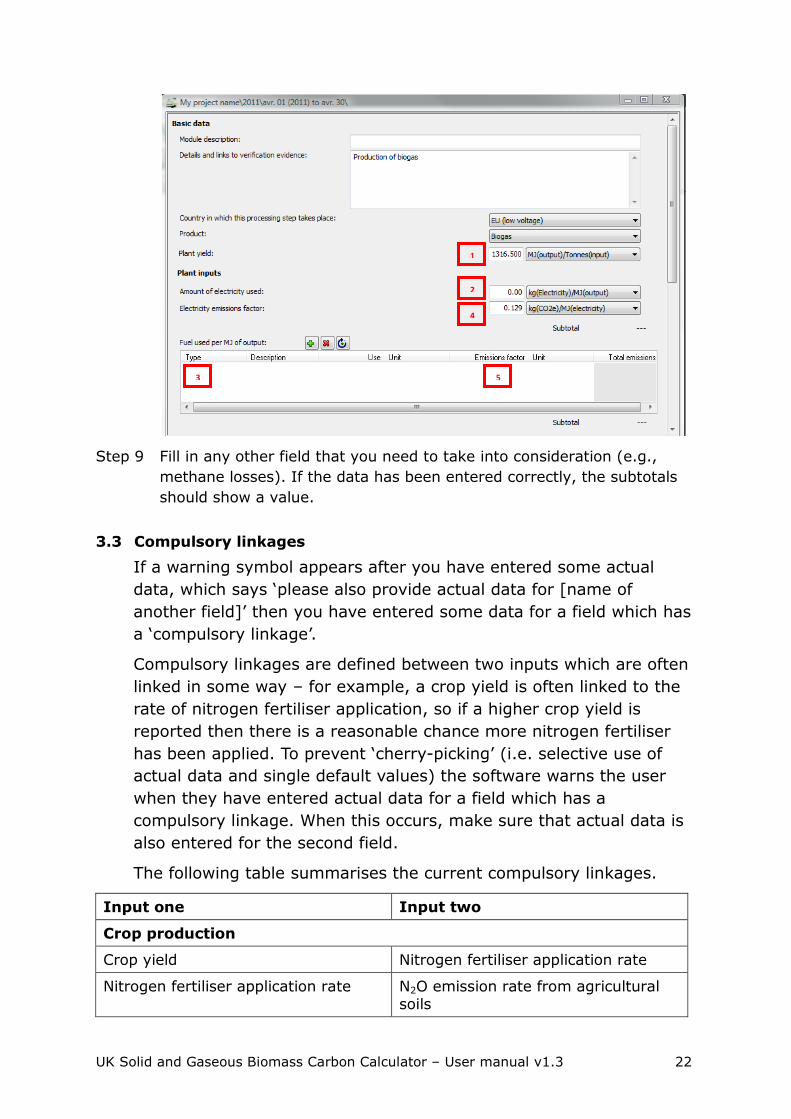
Step 3 Insert the plant yield (i.e. the amount of biogas that is being transferred
to the next supply chain step) in the „Plant yield‟ field (field number 1 in
the screen shot below).
Step 4 Enter the amount of electricity used by the biogas production unit in the
„Amount of electricity used‟ field (field number 2 in the screen shot
below)
Step 5 Enter the amount of heat used in the biogas production unit in the „Fuel
used per MJ of output‟ (field number 3 in the screen shot). For more
information on how to enter actual data, please refer to Section 3.1.
Step 6 You now need to calculate the electricity and heat emission factor, i.e.
the GHG emissions associated with the production of the electricity and
heat used. This calculation cannot be performed in the UK Solid and
Gaseous Biomass Carbon Calculator.
In an Excel spreadsheet, enter:
the default value for the biogas used to produce the electricity (in
g CO2eq / MJ biogas) – E
the electricity efficiency of the CHP unit (in MJ electricity / MJ
biogas) – ηe
the thermal efficiency of the CHP unit (in MJ heat / MJ biogas) –
ηh
the temperature of the useful heat at delivery point (in Kelvin) –
Th
the temperature of the surroundings (in Kelvin) set at 273 Kelvin
– T0
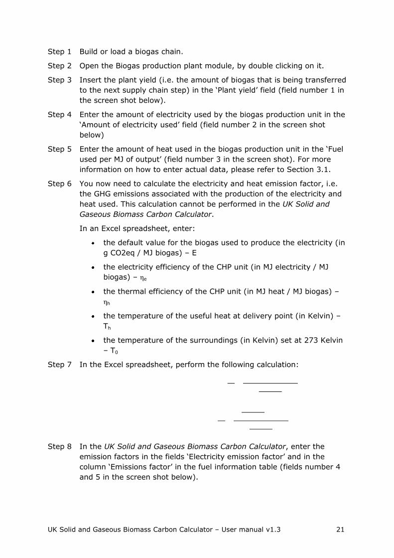
Step 7 In the Excel spreadsheet, perform the following calculation:
Step 8 In the UK Solid and Gaseous Biomass Carbon Calculator, enter the
emission factors in the fields „Electricity emission factor‟ and in the
column „Emissions factor‟ in the fuel information table (fields number 4
and 5 in the screen shot below).
UK Solid and Gaseous Biomass Carbon Calculator – User manual v1.3 22
Step 9 Fill in any other field that you need to take into consideration (e.g.,
methane losses). If the data has been entered correctly, the subtotals
should show a value.
3.3 Compulsory linkages
If a warning symbol appears after you have entered some actual
data, which says „please also provide actual data for [name of
another field]‟ then you have entered some data for a field which has
a „compulsory linkage‟.
Compulsory linkages are defined between two inputs which are often
linked in some way – for example, a crop yield is often linked to the
rate of nitrogen fertiliser application, so if a higher crop yield is
reported then there is a reasonable chance more nitrogen fertiliser
has been applied. To prevent „cherry-picking‟ (i.e. selective use of
actual data and single default values) the software warns the user
when they have entered actual data for a field which has a
compulsory linkage. When this occurs, make sure that actual data is
also entered for the second field.
The following table summarises the current compulsory linkages.
Input one Input two
Crop production
Crop yield Nitrogen fertiliser application rate
Nitrogen fertiliser application rate N2O emission rate from agricultural soils
1
2
3
4
5

UK Solid and Gaseous Biomass Carbon Calculator – User manual v1.3 23
Conversion
Efficiency Any co-product yield
Efficiency Fuel or electricity use
Electricity or heat exported Fuel use
The compulsory linkage between nitrogen fertiliser application rate
and soil N2O emissions is not signalled by a warning sign but
automated in the program. For all fuel chains the N2O emission rate
was calculated using the IPCC Tier 1 methodology based on the
nitrogen fertiliser application rate. For all chains, when the fertiliser
input table is edited in the UK Solid and Gaseous Biomass Carbon
Calculator, the N2O emission rate is automatically recalculated based
on the IPCC Tier 1 approach and the „new‟ N fertiliser application
rate.
3.4 Conservative factor for processing steps
In the methodology for calculating default values for biomass, the
European Commission takes a conservative approach by multiplying
the processing step by a factor of 1.4, thereby increasing emissions
from processing. This conservative approach to the processing step
of default values is continued in the UK Solid and Gaseous Biomass
Carbon Calculator.
In the case of biomass to energy, the processing step refers to any
chipping, pelleting or briquetting steps and any drying and storage
steps that do not happen at cultivation or harvesting site (i.e. the
processing modules are usually separated from the „Crop production‟
and/or „Harvesting‟ modules by a „Feedstock transport‟ module).
However, if actual data is used for the modules in the processing
step, it is possible for this conservative multiplier to be removed.
The conservative factor can only be removed from the conversion
modules for which actual data is provided for all of the following
parameters:
Conversion efficiency
Electricity consumption
Fuel consumption
Chemical inputs
Co-product yield

UK Solid and Gaseous Biomass Carbon Calculator – User manual v1.3 24
The conservative factor can only be removed from the drying and
storage modules that form part of the processing step and for which
actual data is provided for all of the following parameters:
Module efficiency
Electricity consumption
Fuel consumption
Moisture content after drying
This rule applies to each conversion and drying and storage module
individually in the case that there is more than one.
Follow the steps outlined below to remove the conservative factor
from a conversion module.
Step 1 Double click on a „Biomass conversion‟, „Biogas production plant‟,
„Biogas upgrading to biomethane‟ or „Drying and storage‟, module that
you consider to be part of the processing step.
Step 2 Provide actual values for all the relevant input data required in the
module. Refer to the list of relevant inputs described in the paragraph
above.
Step 3 At the end of the module, click on „All data reported in this module are
actual data‟.
The conversion factor of 1.4 will then be removed.
Please note that if the conversion factor was already showing „---‟
before you clicked on „All data reported in this module are actual data‟,
then the module you have opened is not considered part of the
processing step.
3.5 Land use change emission calculations
The UK Solid and Gaseous Biomass Carbon Calculator implements
the land use change emissions calculations as described in the RED
and the European Commission Decision of June 2010 on guidelines
for the calculations of land carbon stock, and the implementation of
this legislation into the Renewables Obligation Order 2011.
As a result of this legislation, it is required that if there has been a
change of use on the land from which the biomass feedstock is
sourced, the emissions associated with this land use change should
be taken into consideration in the calculation of the carbon intensity
of the consignment of biomass.
As a default, the Calculator assumes that no land use change has
taken place, except in the case that clear felled virgin forest is used

UK Solid and Gaseous Biomass Carbon Calculator – User manual v1.3 25
as the feedstock5. However, if you are reporting a land use change,
you must include the emissions due to that land use change in your
carbon intensity and GHG emission saving calculations.
To determine whether there has been a change in the use of the land
from which the biomass feedstock is sourced, you must determine:
The land cover in January 2008 within the following categories:
forest land, grassland, annual cropland, wetlands, settlements
and perennial cropland
The current land cover within the same categories as above
If there is a change in category, land use change emissions must be
included in the carbon intensity calculations.
In the Calculator, there are two different approaches to calculating
emissions from land use change (where land use change has
occurred):
Provide an actual estimate of the annualised emissions due to
land change
Provide the required information under the section „Emissions
from changes in land carbon stocks‟ in the Crop Production
Module to determine the carbon stocks of the previous and actual
land use and the emissions associated with the land use change.
Carbon stocks are estimated as the total of soil organic carbon and
above and below ground vegetation carbon stock. These are
determined based on information on land management practice,
inputs to land, climate region, soil type, domain, land use type,
ecological zone and continent from look-up tables provided in the EC
decision and available on the EU Transparency Platform. Depending
on the land use, not all of these information pieces are necessary,
and the UK Solid and Gaseous Biomass Carbon Calculator will take
you through the pieces of information you need to provide depending
on the previous information selected. See the screen shot below for
an example.
5 For clear felling, land use change emissions will always take place and so the default will be that the land was
forested area on 1 Jan 2008.

UK Solid and Gaseous Biomass Carbon Calculator – User manual v1.3 26
3.6 Entering links to verification evidence
All actual data used must be verifiable. You may wish to record, in
the field at the top of the module „Details and links to verification
evidence‟ cross references to reports or other evidence supporting
the claimed actual data.

UK Solid and Gaseous Biomass Carbon Calculator – User manual v1.3 27
4 Interpreting the results
4.1 Module results
All modules, except for the „Fuel chain‟ modules, the „Power plant‟
module and the „Gas injection to the grid‟ module (i.e. the first and
last modules in a fuel chain), show four intermediate results:
Total for the module in kg CO2e / t output if the output product is
solid or g CO2e / MJ output if the output product is gaseous
This is the total GHG emissions of the module alone, after
multiplication by any allocation factor and conservative factor.
Contribution of the module to the fuel chain in kg CO2e / t output
if the output product is solid or g CO2e / MJ output if the output
product is gaseous
This is the total GHG emissions of the module as integrated into
the chain. It is calculated by taking the „total for this module‟ and
dividing it by any subsequent module efficiency, plant yield and
allocation factor.
Percentage contribution to chain
This represents the contribution of the module to the total fuel
chain GHG emissions.
Total emissions up to the module in kg CO2e / t output if the
output product is solid or g CO2e / MJ output if the output product
is gaseous
This is the total GHG emissions of all the modules upstream of
the specific module and including the specific module. It is
calculated by dividing the „total emission up to this module‟ of the
previous module by the module efficiency or plant yield of the
module looked at, multiplying it by the allocation factor of that
module is relevant, and adding the „total for this module‟ of the
module looked at.
4.2 Fuel chain results
The „Fuel chain Electricity‟, „Fuel chain Heat‟ and „Power plant‟
modules show the final results of a fuel chain, including:
The fuel carbon intensity in kg CO2e / t fuel if the fuel is solid and
in g CO2e / MJ fuel in all cases

UK Solid and Gaseous Biomass Carbon Calculator – User manual v1.3 28
The fuel carbon intensity is the GHG emissions associated with
the biomass fuel burned in the power plant to produce the
electricity and/or heat.
The Electricity or Heat carbon intensity (whichever is relevant) in
g CO2e / MJ electricity or heat and in kg CO2e / MWh electricity or
heat
The electricity or heat carbon intensity is the GHG emissions
associated with the electricity or heat produced from the biomass
fuel.
Please note the following:
o No electricity or heat carbon intensity will be calculated unless
the electricity or heat efficiency has been provided in the Fuel
chain Electricity or Fuel chain Heat module.
o The electricity or heat carbon intensity does only consider
GHG emissions associated with the production and transport
of the biomass fuel. No GHG emissions are associated with the
combustion of the biomass.
The GHG saving in the case of electricity chains.
The GHG saving is calculated based on the electricity carbon
intensity and on the fossil electricity comparator as defined in the
ROO.
Please note the following:
o No GHG saving will be calculated unless the electricity and
heat efficiency (if relevant) has been provided in the Fuel
chain Electricity module.

UK Solid and Gaseous Biomass Carbon Calculator – User manual v1.3 29
5 Preparing reports
Report creation functions have also been included in the UK Solid and
Gaseous Biomass Carbon Calculator. They are available for all energy
types (i.e. electricity, heat and grid injection), although reporting on
carbon intensity is only required for electricity generated from solid
and gaseous biomass. The following report creation functions are
available in the UK Solid and Gaseous Biomass Carbon Calculator:
Module reports that provide an overview of all the data used in a
module.
Project reports containing information on the fuels used, their
characteristics (feedstock type, feedstock country of origin,
previous land use and the carbon intensity), and an overview of
the actual data input to the chains.
Annual reports, which were designed to allow direct submission to
Ofgem. Please note that these reports contain more information
than the minimum Ofgem requirements.
5.1 Module reports (pdf format)
Follow the steps outlined below to create a module report.
Step 1 Double click on a module (for example, the crop harvesting module).
Step 2 Make all the changes you wish to in this module (for example, enter
actual values for the fuel information).
Step 3 Click on the “Print” button at the bottom right of the module.

UK Solid and Gaseous Biomass Carbon Calculator – User manual v1.3 30
Step 4 To print the report, click on the print symbol at the top left corner of the
window.
To save the PDF report, click on the Adobe symbol at the top left corner
of the window.
Step 5 If you are generating a PDF file, you will now be given the option to
change various parameters for this PDF file. If you just want to export a
standard PDF file simply click „OK‟, you will then be given the option to
name the file and specify a location for it.
Please note that this report creation function will only work if you
have an Adobe reader installed on your computer. To install such a
reader, please go to the following website:
http://get.adobe.com/uk/reader/otherversions/.

UK Solid and Gaseous Biomass Carbon Calculator – User manual v1.3 31
5.2 Project reports (pdf format)
Project reports in the UK Solid and Gaseous Biomass Carbon
Calculator contain information on all the fuel chains added by the
generator over a time period specified by the generator. There are
three sections in a project report that the generator can choose
whether to include:
Summary report
Detailed report
Data report
Follow the steps outlined below to create a project report.
Step 1 Click on the “Print” symbol in the top left corner of the UK Solid and
Gaseous Biomass Carbon Calculator
OR
Select “Projects report” in the “Reports” menu.
Step 2 Specify the time period you would like your project report to cover by
ticking the box next to “Specify a period”, then select the first year and
month you would like to include in the report, and then select the last
year and month you would like to include in the report.

UK Solid and Gaseous Biomass Carbon Calculator – User manual v1.3 32
Step 3 If you want to add any information that is saved in a separate file, click
the “Add” button and select the appropriate file.
Check to make sure „OK‟ appears in the valid column, next to the name
of the file you just loaded (if not, then the file loaded does not have
data for the correct year within it, and no data will be added to the
report). Add any other files using the same process. When you have
added all the files required, click the „Next‟ button.
If you want to abandon the report creation, click “Cancel”.
Step 4 Select which of the reports you would like to prepare (Note: all the
reports you select will appear in one PDF document, so if you want
separate documents of all three reports it is best to select only one type
of report at a time), then press „Print or export to PDF‟

UK Solid and Gaseous Biomass Carbon Calculator – User manual v1.3 33
If you would like to abandon the report creation, click “Finish”. If you
would like to change the settings of the first screen, click “Back”.
Step 5 If you only want to print the report, then use the print button on the far
left of the toolbar in the new screen. If you want to generate a PDF file,
click the Adobe symbol in the toolbar.
Step 6 If you are generating a PDF file, you will now be given the option to
change various parameters for this PDF file. If you just want to export a
standard PDF file simply click „OK‟, you will then be given the option to
name the file and specify a location for it.
Please note that this report creation function will only work if you
have an Adobe reader installed on your computer. To install such a
reader, please go to the following website:
http://get.adobe.com/uk/reader/otherversions/.
5.3 Annual reports (xls format)
Follow the steps outlined below to create annual report.
Step 1 Load all the fuel chains that you have used in your power plant over the

UK Solid and Gaseous Biomass Carbon Calculator – User manual v1.3 34
past year. Please note that the fuel chains should be added to the
month in which they were used. There should be one fuel chain for each
consignment of fuel used.
Step 2 In all the fuel chain modules, make sure that you have:
Entered the relevant information on heat and electricity efficiency
of the power plant
Entered a quantity of fuel used
Step 3 Under the „Reports‟ menu, select „Annual report‟.
OR
Click on „Year xxxx‟ in the left-hand panel (xxxx representing the actual
year number).
Step 4 You will then be taken to the annual summary report screen, which
shows an overview of all the fuel loaded in the current reporting year.
For each fuel chain, the table contains the following information:
Internal batch number, if you have entered it in the fuel chain
module
The month in which the fuel was used
The fuel type
The feedstock type
The drying process
The country of origin of the feedstock
The amount of fuel burned
The fuel carbon intensity
And the electricity or heat carbon intensity if relevant.

UK Solid and Gaseous Biomass Carbon Calculator – User manual v1.3 35
If you want to export the table into an xls file, click on „Export‟ and the bottom right of the window.
Step 5 You will then be prompted to enter the pathway under which you would
like to save the file and to enter a file name. Then click „Save‟.

UK Solid and Gaseous Biomass Carbon Calculator – User manual v1.3 36
6 Updates to software and default values
If opened when online, the software will check (via the internet) to
see whether there are any updates of the program or of the default
values available. If updates are found, you will receive a message
shortly after opening the software, asking you whether you would
like to download the latest version of the software or default values.
You can also manually check to make sure you have the most up-to-
date version.
Follow the steps below to manually check for updates.
Step 1 In the „Help‟ menu, select either „Check for default value updates‟ or
„Check for software updates‟.
Step 2 If your network uses a proxy server to access the internet, you will
need to complete the proxy parameters by clicking on the „Proxy
parameters‟ button. You may need to check this with your system
administrator. Once this has been completed, click the „Next‟ button.
Step 3 If there are any updates available for the software, a new screen will
appear indicating which version it is, click „Next‟ and follow the
installation instructions.

UK Solid and Gaseous Biomass Carbon Calculator – User manual v1.3 37
7 Module descriptions
7.1 Units used in the UK Solid and Gaseous Biomass Carbon Calculator
Beside each quantitative information field in the UK Solid and Gaseous Biomass Carbon Calculator, the user can select the unit in
which the data is provided. The most used units are unit of mass (tonne, kilogramme, gram), energy (megajoule) and area (hectares).
When there is uncertainty around what product the units refer to, the
units are provided with the product in parenthesis. For example, agricultural yields are usually expressed in tonnes (feedstock)/ha,
i.e. in tonnes of agricultural feedstock per hectare. The products most often referred to in the calculator are:
Feedstock – this is the primary harvested product from which the
biomass feedstock used in the power plant derives, e.g., sugar cane, forestry residues;
Output – this stands for the product coming out of a module;
Input – this stands for the product going into a module;
CO2e – this stands for the greenhouse gas emissions expressed in CO2 equivalents.
7.2 Fuel chain – Electricity
Basic data
Module description A brief description of the module.
This field is optional.
Details and links to verification evidence
Any further details can be added here, including, for example links to any evidence which supports the actual data used within this module.
This field is optional.
Feedstock information
Feedstock type The primary harvested product from which the biomass feedstock used in the power plant derives.
This field is compulsory.
Moisture content
at collection
The moisture content of the biomass collected.
This field is automatically filled with a default value by the Calculator. Users can replace this value with actual data if
appropriate.
This field is compulsory.
Biomass form The format of the biomass used in the power plant.
This field is compulsory.
UK Solid and Gaseous Biomass Carbon Calculator – User manual v1.3 38
Lower heating
value at combustion point
The energy content of the biomass fuel used in the power
plant.
This field is automatically filled with a default value by the Calculator. Users can replace this value with actual data if
appropriate.
This field is compulsory.
Process type The process type used for the production of the biomass form (if applicable).
This field is compulsory but „Unknown‟ or „n/a‟ can be selected if relevant.
Electricity generation efficiency
Electricity
production only
Select this option if the biomass was burned in a power
plant that only exports electricity and no useful heat.
This field is compulsory.
Electricity co-produced with useful heat
Select this option if the biomass was burned in a power plant producing both electricity and useful heat.
This field is compulsory.
Electricity efficiency
This is the electrical efficiency of the power plant, i.e. the ratio of electricity produced by biomass input. This should
be given as a decimal and reflect the units of energy in the electricity produced per unit of energy in the biomass used.
This field is compulsory.
Heat efficiency If the option „Electricity co-produced with useful heat‟ is selected, it is also necessary to insert the efficiency of heat
production.
In such case, this field is compulsory.
Temperature If the option „Electricity co-produced with useful heat‟ is selected, the temperature of the useful heat also needs to
be provided.
The temperature is used to calculate the proportion of emissions that should be allocated to the useful heat vs.
the electricity.
This field is compulsory if „Electricity co-produced with
useful heat‟ is selected.
Country of origin information
Feedstock country / region of origin
The country or region from which the feedstock is sourced.
This field is compulsory.
Default fuel carbon intensity
This is the default carbon intensity for the Feedstock type / Biomass form / Process type / Country combination. If this
field shows a value of 0 g CO2e / MJ, then it means that no default value for the selected combination exists.
This field is automatically filled by the Calculator.

UK Solid and Gaseous Biomass Carbon Calculator – User manual v1.3 39
Quantity of fuel
used during the reporting month
In this field you can record the amount of biomass used in
the power plant in a particular month or reporting period.
This field is optional but you may wish to use it for your own records.
Land use on 01 Jan 2008
The land use, on 1st January 2008, for the land from which the biomass feedstock is sourced.
This field is compulsory. n/a may be selected if the feedstock is an agricultural or processing residue.
If there has been a change of land use between 1st January 2008, and when the biomass was harvested, it will be necessary to include in the carbon intensity calculations the
emissions associated with that land use change. These calculations are performed in the „Crop production‟ module.
Intermediate results
Fuel chain carbon
intensity
The carbon intensity of the consignment, measured in units
of kilograms of CO2 equivalent released per tonne of fuel used in the power plant and as grams of CO2 equivalent per
MJ of biomass fuel used in the power plant.
Electricity carbon
intensity
The carbon intensity of the electricity produced from the
biomass fuel, measured in units of grams of CO2 equivalent released per megajoule (unit of energy) of electricity produced.
Please note that the electricity carbon intensity will only be calculated if you have provided the information on electricity
and heat efficiency in the „Electricity generation efficiency‟ section.
GHG saving The percentage saving the electricity achieves relative to its fossil fuel equivalent.
The fossil fuel equivalent of electricity is taken from the
European Commission report on sustainability requirements for solid and gaseous biomass sources in electricity, heating
and cooling and has a value of 198 g CO2eq / MJ electricity.
7.3 Fuel chain – Heat
Basic data
Module description A brief description of the module.
This field is optional.
Details and links to verification evidence
Any further details can be added here, including, for example links to any evidence which supports the actual data used within this module.
This field is optional.
Feedstock information
UK Solid and Gaseous Biomass Carbon Calculator – User manual v1.3 40
Feedstock type The primary harvested product from which the biomass
feedstock used in the power plant derives.
This field is compulsory.
Moisture content at collection
The moisture content of the biomass collected.
This field is automatically filled with a default value by the Calculator. Users can replace this value with actual data if
appropriate.
This field is compulsory.
Biomass form The format of the biomass used in the power plant.
This field is compulsory.
Lower heating value at
combustion point
The energy content of the biomass fuel used in the power plant.
This field is automatically filled with a default value by the Calculator. Users can replace this value with actual data if appropriate.
This field is compulsory.
Process type The process used for producing the biomass form (if
applicable).
This field is compulsory but „Unknown‟ or „n/a‟ can be
selected if relevant.
Heat generation efficiency
Heat production only
Select this option if the biomass was burned in a power plant that only exports heat.
This field is compulsory.
Heat co-produced with electricity
Select this option if the biomass was burned in a power plant producing both electricity and heat.
This field is compulsory.
Heat efficiency This is the thermal efficiency of the power plant, i.e. the
ratio of heat produced by biomass input. This should be given as a decimal and reflect the units of energy in the
heat produced per unit of energy in the biomass used.
This field is compulsory.
Electricity efficiency
If the option „Heat co-produced with electricity‟ is selected, it is also necessary to insert the efficiency of electricity production.
In such case, this field is compulsory.
Temperature If the option „Heat co-produced with electricity‟ is selected,
the temperature of the heat also needs to be provided.
The temperature is used to calculate the proportion of
emissions that should be allocated to the heat vs. the electricity.
This field is compulsory if „Heat co-produced with electricity‟
is selected.

UK Solid and Gaseous Biomass Carbon Calculator – User manual v1.3 41
Country of origin information
Feedstock country / region of origin
The country or region from which the feedstock is sourced.
This field is compulsory.
Default fuel carbon intensity
This is the default carbon intensity for the Feedstock type / Biomass form / Process type / Country combination. If this
field shows a value of 0 g CO2e / MJ, then it means that no default value for the selected combination exists.
This field is automatically filled by the Calculator.
Quantity of fuel used during the
reporting month
In this field you can record the amount of biomass used in the power plant in a particular month or reporting period.
This field is optional but you may wish to use it for your own records.
Land use on 01 Jan 2008
The land use, on 1st January 2008, for the land from which the biomass feedstock is sourced.
This field is compulsory. n/a may be selected if the feedstock is an agricultural or processing residue.
If there has been a change of land use between 1st January
2008, and when the biomass was harvested, it will be necessary to include in the carbon intensity calculations the
emissions associated with that land use change. These calculations are performed in the „Crop production‟ module.
Intermediate results
Fuel chain carbon intensity
The carbon intensity of the consignment, measured in units of kilograms of CO2 equivalent released per tonne of
biomass fuel and as grams of CO2 equivalent per MJ of biomass fuel or biogas used in the power plant.
Heat carbon intensity
The carbon intensity of the heat produced from the biomass fuel, measured in units of grams of CO2 equivalent released
per megajoule (unit of energy) of heat produced.
Please note that the heat carbon intensity will only be calculated if you have provided the relevant information
under the „Heat generation efficiency‟ section.
GHG saving No GHG saving is currently calculated for heat as the fossil
fuel comparator is not defined yet.
7.4 Fuel chain – Gas
Basic data
Module description A brief description of the module.
This field is optional.

UK Solid and Gaseous Biomass Carbon Calculator – User manual v1.3 42
Details and links to
verification evidence
Any further details can be added here, including, for
example links to any evidence which supports the actual data used within this module.
This field is optional.
Feedstock information
Feedstock type The primary harvested product from which the biomass feedstock used in the power plant derives.
This field is compulsory.
Moisture content at collection
The moisture content of the biomass collected.
This field is automatically filled with a default value by the
Calculator. Users can replace this value with actual data if appropriate.
This field is compulsory.
Biomass form The format of the biomass used in the power plant.
This field is compulsory.
Process type The process used for producing the biogas.
This field is compulsory but „Unknown‟ or „n/a‟ can be
selected if relevant.
Country of origin information
Feedstock country / region of origin
The country or region from which the feedstock is sourced.
This field is compulsory.
Default fuel carbon intensity
This is the default carbon intensity for the Feedstock type / Biomass form / Process type / Country combination. If this
field shows a value of 0 g CO2e / MJ, then it means that no default value for the selected combination exists.
This field is automatically filled by the Calculator.
Quantity of fuel
used during the reporting month
In this field you can record the amount of biomass used in
the power plant in a particular month or reporting period.
This field is optional but you may wish to use it for your own records.
Land use on 01 Jan 2008
The land use, on 1st January 2008, for the land from which the biomass feedstock is sourced.
This field is compulsory. n/a may be selected if the feedstock is an agricultural or processing residue.
If there has been a change of land use between 1st January 2008, and when the biomass was harvested, it will be necessary to include in the carbon intensity calculations the
emissions associated with that land use change. These calculations are performed in the „Crop production‟ module.
If the biomass being used is a virgin forest that is being clear-felled, there will always be a land use.
Intermediate results

UK Solid and Gaseous Biomass Carbon Calculator – User manual v1.3 43
Fuel carbon
intensity
The carbon intensity of the consignment, measured in units
of kilograms of CO2 equivalent released per MJ of biomethane injected to the national gas grid.
GHG saving No GHG saving is currently calculated for biomethane as the fossil fuel comparator is not defined yet.
7.5 Crop production6
Basic data
Module description
A brief description of the module.
This field is optional.
Details and links to verification
evidence
Any further details can be added here, including, for example, links to any evidence which supports the actual
data used within this module.
This field is optional.
Crop yield The quantity of feedstock produced per unit area. The percentage moisture of crops can vary, and this will affect
the yield achieved. The yield reported here should be for the moisture content reported in the fuel chain module as the moisture content at the point of collection. This field is
automatically filled by the Calculator but can be updated with actual data if it is available.
This field is compulsory.
Emissions from changes in land carbon stocks
No change in land carbon stock
This option should be selected if the cultivation of biomass did not lead to any change in land carbon stocks between
the actual land use and land use on January 1st, 2008.
Use actual data
for land use change emissions
This option should be selected if the user wishes to report
land use change emissions based on actual data or another methodology than the default calculation methodology outlined in EU Decision 2010/335/EU.
The actual emissions should be put in the blank data field.
Use the default
methodology to calculate
emissions from land use change
This option should be selected if the user wishes to use the
default methodology to calculate emissions from land use change.
6 Please note that the crop production input data is missing for the long rotation forestry chains. This will be
updated in later versions of the calculator, once the appropriate data for these chains has been made
available. Users should make sure they add the relevant input data to these chains in order to calculate the
carbon intensity.

UK Solid and Gaseous Biomass Carbon Calculator – User manual v1.3 44
Land use Land use in January 2008 or current land use.
This field is only available if the option „Use the default methodology to calculate emissions from land use change‟ is selected, in which case it is mandatory.
If clear-felled virgin forestry (lightly forested) is used as a feedstock, there will always be land use change. For “current
land use” the management of the land following felling should be selected. If the land is unmanaged, “scrubland” should be selected from the drop-down list. If the land is
managed as something else, e.g. a crop or a forest plantation, this should be selected from the drop-down list.
Land management
practice
Land management practice in January 2008 or actual land management practice.
This field is only available if the option „Use the default methodology to calculate emissions from land use change‟ is selected and is only applicable for certain types of land use,
in which case it is mandatory.
Input to land Input to land in January 2008 or actual input to land.
This field is only available if the option „Use the default methodology to calculate emissions from land use change‟ is
selected and is only applicable for certain types of land use, in which case it is mandatory.
Climate region Climate type of the region where the land used to grow the biomass feedstock is located.
This field is only available if the option „Use the default
methodology to calculate emissions from land use change‟ is selected, in which case it is mandatory.
Soil type Soil type of the land use to grow the biomass feedstock.
This field is only available if the option „Use the default
methodology to calculate emissions from land use change‟ is selected, in which case it is mandatory.
Domain Climate domain of the region where the land used to grow the biomass feedstock is located.
This field is only available if the option „Use the default
methodology to calculate emissions from land use change‟ is selected and is only applicable for certain types of land use,
in which case it is mandatory.
Land use type Further information on the land use type for the land use in
January 2008 or for the actual (current) land use.
This field is only available if the option „Use the default methodology to calculate emissions from land use change‟ is
selected and is only applicable for certain types of land use, in which case it is mandatory.

UK Solid and Gaseous Biomass Carbon Calculator – User manual v1.3 45
Ecological zone Ecological zone where the land used to grow the biomass
feedstock is located.
This field is only available if the option „Use the default methodology to calculate emissions from land use change‟ is
selected and is only applicable for certain types of land use, in which case it is mandatory.
Continent Continent on which the land used to grow the biomass feedstock is located.
This field is only available if the option „Use the default methodology to calculate emissions from land use change‟ is selected and is only applicable for certain types of land use,
in which case it is mandatory.
If forest plantation has been selected as the land use type,
there may be an option to select the continent with either <= 20 years or >20 years. In the case that the land use change is from virgin forest to forest plantation, the option
<= 20 years should be selected (i.e. a plantation that has been growing for less than or equal to 20 years).
Carbon stock Carbon stock of the land as used in January 2008 and actual (current) carbon stock.
This field cannot be changed by users but is calculated based on the previous information.
Subtotal Emissions from land use change in kilograms of CO2 equivalent per tonne of feedstock.
Emissions from cultivation
Rate of nitrous
oxide emissions per hectare
The rate at which nitrous oxide (N2O) emissions are
produced from the soil on which the feedstock was grown.
The N2O emission rate was calculated using the IPCC Tier 1 methodology based on the nitrogen fertiliser application
rate.
Most users will not enter their own values in this field.
However, if an N2O value has been calculated according to a method consistent with the rules set out in the IPCC Guidelines for National Greenhouse Gas Inventories, then it
can be entered here.
Subtotal Emissions of nitrous oxide in kilograms of CO2 equivalent per
tonne of feedstock.
Farming inputs
Fertilisers All information relating to the use of fertilisers during feedstock growth can be entered in this table.
Type The type of fertiliser used.
Application rate The rate at which the fertiliser was applied. Note: this is
measured in the industry standard kilograms of „nutrient‟ per hectare.

UK Solid and Gaseous Biomass Carbon Calculator – User manual v1.3 46
Emissions factor The emissions which are produced during manufacture and
transport of every kilogram of fertiliser (that is kg of nutrient, not of product).
Most users will not need to manually change this field, as
the software will automatically select the correct default emission factor based on the fertiliser „Type‟ selected.
Nitrogen content The nitrogen content of the fertiliser applied.
Most users will not need to manually change this field, as
the software will automatically select the correct value based on the fertiliser „Type‟ selected.
Nitrogen content is measured in units of kilograms of
nitrogen per kilogram of the main nutrient. If nitrogen is the main nutrient, then the nitrogen content will be 1. If there is
negligible nitrogen in the fertiliser, the nitrogen content will be 0.
Subtotal Emissions due to fertiliser production and application in kilogram of CO2 equivalent per tonne of feedstock.
Pesticide application rate
The quantity of all pesticides applied (measured in kilograms of active ingredient, not kilograms of product) per hectare.
Pesticide emissions factor
The emissions which occur during manufacture and transport of every kilogram of pesticide (that is kg of active ingredient, not of product).
Most users are expected to rely on the default value.
Subtotal Emissions due to pesticide production and application in
kilogram of CO2 equivalent per tonne of feedstock.
Other input All information relating to products used during feedstock
farming other than fertilisers, pesticides and fuel.
Type Type of other input – e.g. seeding materials.
Use The quantity of the other input used.
Emissions factor The emissions resulting from the production and use of each
unit of other input.
Most users are expected to rely on default values that will be
automatically selected by the software based on the „Type‟ of other input chosen.
Subtotal Emissions due to production and input of other materials in kilograms of CO2 equivalent per tonne of feedstock.
On-farm fuel use All information relating to the on-farm use of fuels such as diesel, with the exception of fuel used during harvesting activities. Note: more than one type of fuel can be entered
into this table
Type Type of fuel used – e.g., diesel for tractors, electricity to
power pumps for irrigation, etc.

UK Solid and Gaseous Biomass Carbon Calculator – User manual v1.3 47
Use The quantity of fuel used (Note: this is the quantity of fuel
used in cultivation of this crop, not total on-farm fuel use and excluding fuel used for harvesting activities).
Emissions factor The emissions resulting from the production and use of each unit of fuel.
Almost all users will rely on the default value selected by the
software.
Subtotal Emissions due to fuel production and on-farm use in
kilograms of CO2 equivalent per tonne of feedstock.
Intermediate results
Total for this module
The total GHG emissions of this module (measured in units of kilograms of CO2e) per tonne of feedstock produced.
Contribution of this module to
fuel chain
The total GHG emissions (measured in units of kilograms of CO2e) produced from this stage of the fuel chain, per tonne
of final biomass type used.
Percentage
contribution to chain
The percentage contribution this module makes to the total
GHG emissions of the fuel chain. This value may be greater than 100% because there may be a very large co-product credit in another step which reduces the total chain GHG
emissions to less than the emissions from this step alone.
Total emissions
up to this module
The total GHG emissions of this module and all the previous
ones (measured in units of kilogram of CO2e) per tonne of output of this module.
7.6 Harvesting, extraction and roadside processing7
Basic data
Module
description
A brief description of the module.
This field is optional.
Details and links
to verification evidence
Any further details can be added here, including, for
example, links to any evidence which supports the actual data used within this module.
This field is optional.
Module efficiency The efficiency with which the feedstock is harvested. Any
losses should be included in this field. For example if 20% of the feedstock is “lost” during the harvesting phase, 0.8 should be inserted into this field.
Farming inputs
7 Please note that the harvesting input data is missing for the long rotation forestry chains. This will be updated
in later versions of the calculator, once the appropriate data for these chains has been made available. Users
should make sure they add the relevant input data to these chains in order to calculate the carbon intensity.

UK Solid and Gaseous Biomass Carbon Calculator – User manual v1.3 48
Fuel information All information relating to the on-farm use of fuels such as
diesel for harvesting, extraction and/or roadside processing activities. Note: more than one type of fuel can be entered into this table
Type Type of fuel used – e.g., diesel for harvesters.
Use The quantity of fuel used (Note: this is the quantity of fuel used for the harvesting of the feedstock itself).
Emissions factor The emissions resulting from the production and use of each unit of fuel.
Almost all users will rely on the default value selected by the
software.
Subtotal Emissions due to fuel production and on-farm use in
kilograms of CO2 equivalent per tonne of feedstock.
Intermediate results
Total for this module
The total GHG emissions of this module (measured in units of kilograms of CO2e) per tonne of feedstock produced.
Contribution of this module to
fuel chain
The total GHG emissions (measured in units of kilograms of CO2e) produced from this stage of the fuel chain, per tonne
of final biomass type used.
Percentage
contribution to chain
The percentage contribution this module makes to the total
GHG emissions of the fuel chain. This value may be greater than 100% because there may be a very large co-product credit in another step which reduces the total chain GHG
emissions to less than the emissions from this step alone.
Total emissions
up to this module
The total GHG emissions of this module and all the previous
ones (measured in units of kilogram of CO2e) per tonne of output of this module.
7.7 Drying and storage
Basic data
Module
description
A brief description of the module.
This field is optional.
Details and links
to verification evidence
Any further details can be added here, including, for
example, links to any evidence which supports the actual data used within this module.
This field is optional.

UK Solid and Gaseous Biomass Carbon Calculator – User manual v1.3 49
Country in which
this processing step takes place
The country in which this drying and/or storage occurs. This
information is needed for the software to select the appropriate emissions factor for electricity if required (see below).
This drop down list may also contain a few non-country options (e.g., local CCGT, EU (medium voltage), etc.). Select
these options if the electricity used is not taken from the national grid.
Module efficiency The efficiency with which the feedstock is dried. Any losses should be included in this field. For example if 20% of the feedstock is “lost” during the drying phase, 0.8 should be
inserted into this field.
Moisture content
after drying
The moisture content of the biomass after this particular
drying phase.
This field is compulsory.
Amount of electricity used
The total quantity of electricity used during this drying and storage step.
Electricity emissions factor
The emissions resulting from the production and use of each unit of electricity.
Subtotal Emissions due to electricity production and consumption in kilograms of CO2 equivalent per tonne of crop.
Fuel information
Type Type of fuel used – e.g., diesel used in burners to provide
heat for drying, etc.
Use The quantity of fuel used during this drying and storage
step.
Emissions factor The emissions resulting from the production and use of each
unit of fuel.
Most users are expected to rely on the default value based on information provided in the „Type‟ field.
Note: Since the harvesting and cultivation data is missing for the long rotation forestry chains, there is no default
emissions factor for wood chips produced from long rotation forestry. Therefore, if a long rotation forestry chain is loaded, and biomass is used as the process fuel for drying,
the user must manually insert the carbon intensity of the biomass into this module. The carbon intensity of the
biomass can be calculated separately in the calculator in the usual way, i.e. by constructing a representative chain and adding all the relevant inputs and efficiencies.
Subtotal Emissions due to fuel production and consumption in kilograms of CO2 equivalent per tonne of crop.
Conservative factor

UK Solid and Gaseous Biomass Carbon Calculator – User manual v1.3 50
All data reported
in this module are actual data
This option should be selected if all the data reported in the
module are actual data.
This field is only relevant if the „Drying and storage‟ module is part of the processing step (i.e. not part of the cultivation
step – see Section 3.4 for more information).
If it is selected, the conservative factor (factor by which the
„Total for this module‟ will be multiplied before the contribution of the module to the entire fuel chain is calculated) will be removed.
Intermediate results
Total for this module
The total GHG emissions of this module (measured in units of kilograms of CO2e) per tonne of feedstock produced.
Contribution of this module to fuel chain
The total GHG emissions (measured in units of kilograms of CO2e) produced from this stage of the fuel chain, per tonne of final biomass type used.
Percentage contribution to
chain
The percentage contribution this module makes to the total GHG emissions of the fuel chain. This value may be greater
than 100% because there may be a very large co-product credit in another step which reduces the total chain GHG
emissions to less than the emissions from this step alone.
Total emissions
up to this module
The total GHG emissions of this module and all the previous
ones (measured in units of kilogram of CO2e) per tonne of output of this module.
7.8 Feedstock transport
Basic data
Module
description
A brief description of the module.
This field is optional.
Details and links
to verification evidence
Any further details can be added here, including, for
example, links to any evidence which supports the actual data used within this module.
This field is optional.
Country The country in which this transport step begins.
This is currently an optional field.
Transport mode The mode of transport used – e.g., truck, rail, etc.
Density of dry
product
Density of the product transported at 0% moisture content.
The actual density will be calculated by the Calculator taking into account the dry product density and the moisture
content of the product based on the moisture content as inputted in previous modules.

UK Solid and Gaseous Biomass Carbon Calculator – User manual v1.3 51
Energy intensity
of transport
The energy intensity of this transport mode. Most users will
rely on the software to select the appropriate default value on the basis of the mode of transport selected.
This energy intensity depends on the transport mode and
the product density.
Distance
transported
The distance over which the product is transported by the
selected mode.
Module efficiency Efficiency of the transport step in tonnes of output feedstock
per tonne of input feedstock – this is especially to account for grain losses during transport.
Fuel information
Type Type of fuel used. If several fuels are entered, it will be
necessary to know how much of each fuel is used (see next field).
Use The quantity of fuel used during this transport step – this value is automatically calculated based on the transport mode and distance specified. If more than one fuel is used
you can specify how much of each fuel type is used in this field.
Emissions factor The emissions resulting from the production and use of each unit of fuel.
Most users are expected to rely on the default value based on information provided in the „Type‟ field.
Subtotal Emissions due to fuel production and consumption in kilograms of CO2 equivalent per tonne of output from this module (this subtotal excludes the exhaust gas emissions).
Exhaust gas emissions
This field is automatically calculated based on the transport mode selected.
Intermediate results
Total for this module
The total GHG emissions of this module (measured in units of kilograms of CO2e) per tonne of feedstock produced.
Contribution of this module to fuel chain
The total GHG emissions (measured in units of kilograms of CO2e) produced from this stage of the fuel chain, per tonne of final biomass type used.
Percentage contribution to
chain
The percentage contribution this module makes to the total GHG emissions of the fuel chain. This value may be greater
than 100% because there may be a very large co-product credit in another step which reduces the total chain GHG
emissions to less than the emissions from this step alone.
Total emissions
up to this module
The total GHG emissions of this module and all the previous
ones (measured in units of kilogram of CO2e) per tonne of output of this module.

UK Solid and Gaseous Biomass Carbon Calculator – User manual v1.3 52
7.9 Gas transport
Basic data
Module description
A brief description of the module.
This field is optional.
Details and links to verification evidence
Any further details can be added here, including, for example, links to any evidence which supports the actual data used within this module.
This field is optional.
Country The country in which this transport step begins.
This is currently an optional field.
Transport mode The mode of transport used – e.g., pipeline etc.
Distance transported
The distance over which the product is transported by the selected mode.
Energy intensity of transport
The energy intensity of this transport mode. Most users will rely on the software to select the appropriate default value
on the basis of the mode of transport selected.
Module efficiency Efficiency of the transport step in tonnes of output feedstock
per tonne of input feedstock – this is especially to account for grain losses during transport.
Fuel information
Type Type of fuel used. If several fuels are entered, it will be
necessary to know how much of each fuel is used (see next field).
Use The quantity of fuel used during this transport step – this value is automatically calculated based on the transport mode and distance specified. If more than one fuel is used
you can specify how much of each fuel type is used in this field.
Emissions factor The emissions resulting from the production and use of each unit of fuel.
Most users are expected to rely on the default value based on information provided in the „Type‟ field.
Subtotal Emissions due to fuel production and consumption in kilograms of CO2 equivalent per tonne of output from this module (this subtotal excludes the exhaust gas emissions).
Exhaust gas emissions
This field is automatically calculated based on the transport mode selected.
Intermediate results
Total for this module
The total GHG emissions of this module (measured in units of grams of CO2e) per MJ of gas produced.

UK Solid and Gaseous Biomass Carbon Calculator – User manual v1.3 53
Contribution of
this module to fuel chain
The total GHG emissions (measured in units of grams of
CO2e) produced from this stage of the fuel chain, per MJ of biogas.
Percentage contribution to chain
The percentage contribution this module makes to the total GHG emissions of the fuel chain. This value may be greater than 100% because there may be a very large co-product
credit in another step which reduces the total chain GHG emissions to less than the emissions from this step alone.
Total emissions up to this module
The total GHG emissions of this module and all the previous ones (measured in units of grams of CO2e) per MJ of gas.
7.10 Biomass processing (chipping, briquetting, pelleting)
Basic data
Module
description
A brief description of the module.
This field is optional.
Details and links
to verification evidence
Any further details can be added here, including, for
example, links to any evidence which supports the actual data used within this module.
This field is optional.
Country in which
this processing step takes place
The country in which this plant is located. This information is
needed by the software to select the appropriate emissions factor for electricity (see below).
This drop down list may also contain a few non-country
options (e.g., local CCGT, EU (medium voltage), etc.). Select these options if the electricity used is not taken from the
national grid.
Product Product produced by this module – e.g., wood pellets,
energy grass chips, etc.
Plant yield Quantity of output per quantity of input (measured in units
of mass such as tonnes or kilograms), e.g., tonnes energy grass pellets per tonne energy grass chips.
Moisture content
of output product
Moisture content of the product produced by this module
(measured in %).
Plant inputs
Amount of electricity used
The total quantity of electricity used (per tonne of output) during this conversion step.
Electricity emissions factor
The emissions resulting from the production and use of each unit of electricity.
Subtotal Emissions from the production and consumption of electricity in kilograms of CO2 equivalent per tonne of output from this
module.

UK Solid and Gaseous Biomass Carbon Calculator – User manual v1.3 54
Fuel used per tonne of output
Type Type of fuel used – e.g. natural gas burnt in a boiler to provide process heat, etc.
Use The quantity of fuel used during this conversion step, per tonne of output.
Emissions factor The emissions resulting from the production and use of each unit of fuel.
Most users are expected to rely on the default value based on information provided in the „Type‟ field.
Subtotal Emissions from the production and consumption of fuel in
kilograms of CO2 equivalent per tonne of output from this module.
Chemicals
Type Type of chemical used – e.g., n-hexane used to produce
rapeseed oil and rapeseed meal from oilseed rape, etc.
Use The quantity of chemical used during this conversion step,
per tonne of output.
Emissions factor The emissions resulting from the production and use of each
unit of chemical.
Most users are expected to rely on the default value based
on information provided in the „Type‟ field.
Subtotal Emissions from the production and consumption of
chemicals in kilograms of CO2 equivalent per tonne of output from this module.
Co-products
Name The name of the co-product produced by this conversion
process.
Use The market in which the co-product is used – e.g. for animal
feed, for fertiliser etc.
Description If the „Name‟ and/or „Use‟ of a particular co-product are not specified in the software, they can be recorded in the
description field.
Yield Quantity of co-product produced per tonne of output from
this conversion module.

UK Solid and Gaseous Biomass Carbon Calculator – User manual v1.3 55
Co-product credit The credit attributed to this use of the selected co-product.
Note: if the „Co-product credit‟ is a value other than zero, then the „Energy Content‟ (see below) must be zero.
See the Renewable Energy Directive Annex V paragraph 16
to 18 for the rules to follow to determine whether a co-product is eligible for a credit or should be taken into
account through the allocation factor.
In general, only excess electricity from a local CHP plant can be eligible for a credit, except where the fuel used in the
cogeneration unit is a co-product other than an agricultural crop residue.
Energy Content The energy content of this co-product.
Note: if the „Co-product credit‟ is zero, then the „Energy
Content‟ must be a value other than zero.
If the co-product is not eligible for a credit (see row above), then it must be taken into account from the allocation factor
by specifying the energy content of the co-product.
Credit or debit for
co-products
This value shows the total impact of the co-products. If the
value is negative, then the co-products have the effect of reducing the overall carbon intensity of the fuel chain. If the
value is positive, then the co-products have increased the carbon intensity of the fuel chain.
Share of emissions allocated to the
output product
The value shows the allocation factor for the main output products. If the value is 100%, it means that all GHG emissions up to this point in the chain are allocated to the
output of the module. If it is less than 100%, it means that only a portion of the emissions are allocated to the output.
Conservative factor
All data reported
in this module are actual data
This option should be selected if all the data reported in the
module are actual data.
This field is only relevant if the „Biomass processing‟ module
is part of the processing step (i.e. not part of the cultivation step – see Section 3.4 for more information).
If it is selected, the conservative factor (factor by which the
„Total for this module‟ will be multiplied before the contribution of the module to the entire fuel chain is
calculated) will be removed.
Intermediate results
Total for this module
The total GHG emissions of this module (measured in units of kilograms of CO2e) per tonne of feedstock produced.
Contribution of this module to
fuel chain
The total GHG emissions (measured in units of kilograms of CO2e) produced from this stage of the fuel chain, per tonne
of final biomass type used.

UK Solid and Gaseous Biomass Carbon Calculator – User manual v1.3 56
Percentage
contribution to chain
The percentage contribution this module makes to the total
GHG emissions of the fuel chain. This value may be greater than 100% because there may be a very large co-product credit in another step which reduces the total chain GHG
emissions to less than the emissions from this step alone.
Total emissions
up to this module
The total GHG emissions of this module and all the previous
ones (measured in units of kilogram of CO2e) per tonne of output of this module.
7.11 Conversion of biomass feedstock to biogas
Basic data
Module
description
A brief description of the module.
This field is optional.
Details and links
to verification evidence
Any further details can be added here, including, for
example, links to any evidence which supports the actual data used within this module.
This field is optional.
Country in which
this processing step takes place
The country in which this plant is located. This information is
needed by the software to select the appropriate emissions factor for electricity (see below).
This drop down list may also contain a few non-country
options (e.g., local CCGT, EU (medium voltage), etc.). Select these options if the electricity used is not taken from the
national grid.
Product Product produced by this module – e.g., biogas or
biomethane.
Plant yield Quantity of output per quantity of input (measured in units
of MJ output per tonne input).
Plant inputs
Amount of electricity used
The total quantity of electricity used (per MJ of output) during this conversion step.
Electricity emissions factor
The emissions resulting from the production and use of each unit of electricity.
Subtotal Emissions from the production and consumption of electricity in kilograms of CO2 equivalent per MJ of output from this module.
Fuel used per MJ of output
Type Type of fuel used – e.g. natural gas burnt in a boiler to provide process heat, etc.
Use The quantity of fuel used during this conversion step, per MJ of output.

UK Solid and Gaseous Biomass Carbon Calculator – User manual v1.3 57
Emissions factor The emissions resulting from the production and use of each
unit of fuel.
Most users are expected to rely on the default value based on information provided in the „Type‟ field.
Subtotal Emissions from the production and consumption of fuel in kilograms of CO2 equivalent per MJ of output from this
module.
Chemicals
Type Type of chemical used – e.g., n-hexane used to produce rapeseed oil and rapeseed meal from oilseed rape, etc.
Use The quantity of chemical used during this conversion step, per MJ of output.
Emissions factor The emissions resulting from the production and use of each unit of chemical.
Most users are expected to rely on the default value based on information provided in the „Type‟ field.
Subtotal Emissions from the production and consumption of chemicals in kilograms of CO2 equivalent per MJ of output from this module.
Co-products
Name The name of the co-product produced by this conversion process.
Use The market in which the co-product is used – e.g. for animal feed, for fertiliser etc.
Description If the „Name‟ and/or „Use‟ of a particular co-product are not specified in the software, they can be recorded in the description field.
Yield Quantity of co-product produced per MJ of output from this conversion module.
Co-product credit The credit attributed to this use of the selected co-product. Note: if the „Co-product credit‟ is a value other than zero,
then the „Energy Content‟ (see below) must be zero.
See the Renewable Energy Directive Annex V paragraph 16
to 18 for the rules to follow to determine whether a co-product is eligible for a credit or should be taken into account through the allocation factor.
In general, only excess electricity from a local CHP plant can be eligible for a credit, except where the fuel used in the
cogeneration unit is a co-product other than an agricultural crop residue.

UK Solid and Gaseous Biomass Carbon Calculator – User manual v1.3 58
Energy Content The energy content of this co-product.
Note: if the „Co-product credit‟ is zero, then the „Energy Content‟ must be a value other than zero.
If the co-product is not eligible for a credit (see row above),
then it must be taken into account from the allocation factor by specifying the energy content of the co-product.
Credit or debit for co-products
This value shows the total impact of the co-products. If the value is negative, then the co-products have the effect of
reducing the overall carbon intensity of the fuel chain. If the value is positive, then the co-products have increased the carbon intensity of the fuel chain.
Share of emissions
allocated to the output product
The value shows the allocation factor for the main output products. If the value is 100%, it means that all GHG
emissions up to this point in the chain are allocated to the output of the module. If it is less than 100%, it means that
only a portion of the emissions are allocated to the output.
Other
Methane losses Methane losses during the conversion step, measured in grams of methane per MJ of output from this module. The
methane losses are accounted as GHG emissions from the module, assuming a Global Warming Potential for methane of 25.
Conservative factor
All data reported
in this module are actual data
This option should be selected if all the data reported in the
module are actual data.
This field is only relevant if the „Biomass processing‟ module
is part of the processing step (i.e. not part of the cultivation step – see Section 3.4 for more information).
If it is selected, the conservative factor (factor by which the „Total for this module‟ will be multiplied before the contribution of the module to the entire fuel chain is
calculated) will be removed.
Intermediate results
Total for this module
The total GHG emissions of this module (measured in units of grams of CO2e) per MJ of biogas produced.
Contribution of this module to
fuel chain
The total GHG emissions (measured in units of grams of CO2e) produced from this stage of the fuel chain, per MJ of
biogas produced.
Percentage
contribution to chain
The percentage contribution this module makes to the total
GHG emissions of the fuel chain. This value may be greater than 100% because there may be a very large co-product credit in another step which reduces the total chain GHG
emissions to less than the emissions from this step alone.

UK Solid and Gaseous Biomass Carbon Calculator – User manual v1.3 59
Total emissions
up to this module
The total GHG emissions of this module and all the previous
ones (measured in units of grams of CO2e) per MJ of output of this module.
7.12 Biogas upgrading
Basic data
Module
description
A brief description of the module.
This field is optional.
Details and links
to verification evidence
Any further details can be added here, including, for
example, links to any evidence which supports the actual data used within this module.
This field is optional.
Country in which this processing
step takes place
The country in which this plant is located. This information is needed by the software to select the appropriate emissions
factor for electricity (see below).
This drop down list may also contain a few non-country
options (e.g., local CCGT, EU (medium voltage), etc.). Select these options if the electricity used is not taken from the national grid.
Product Product produced by this module – e.g., biomethane.
Plant yield Quantity of output per quantity of input (measured in units of MJ output per MJ input).
Plant inputs
Amount of electricity used
The total quantity of electricity used (per MJ of output) during this conversion step.
Electricity emissions factor
The emissions resulting from the production and use of each unit of electricity.
Subtotal Emissions from the production and consumption of electricity in kilograms of CO2 equivalent per MJ of output from this
module.
Fuel used per MJ of output
Type Type of fuel used – e.g. natural gas burnt in a boiler to provide process heat, etc.
Use The quantity of fuel used during this conversion step, per MJ of output.
Emissions factor The emissions resulting from the production and use of each unit of fuel.
Most users are expected to rely on the default value based on information provided in the „Type‟ field.

UK Solid and Gaseous Biomass Carbon Calculator – User manual v1.3 60
Subtotal Emissions from the production and consumption of fuel in
kilograms of CO2 equivalent per MJ of output from this module.
Chemicals
Type Type of chemical used – e.g., n-hexane used to produce
rapeseed oil and rapeseed meal from oilseed rape, etc.
Use The quantity of chemical used during this conversion step,
per MJ of output.
Emissions factor The emissions resulting from the production and use of each unit of chemical.
Most users are expected to rely on the default value based on information provided in the „Type‟ field.
Subtotal Emissions from the production and consumption of chemicals in kilograms of CO2 equivalent per MJ of output
from this module.
Co-products
Name The name of the co-product produced by this conversion process.
Use The market in which the co-product is used – e.g. for animal feed, for fertiliser etc.
Description If the „Name‟ and/or „Use‟ of a particular co-product are not specified in the software, they can be recorded in the
description field.
Yield Quantity of co-product produced per MJ of output from this
conversion module.
Co-product credit The credit attributed to this use of the selected co-product.
Note: if the „Co-product credit‟ is a value other than zero, then the „Energy Content‟ (see below) must be zero.
See the Renewable Energy Directive Annex V paragraph 16
to 18 for the rules to follow to determine whether a co-product is eligible for a credit or should be taken into
account through the allocation factor.
In general, only excess electricity from a local CHP plant can be eligible for a credit, except where the fuel used in the
cogeneration unit is a co-product other than an agricultural crop residue.
Energy Content The energy content of this co-product.
Note: if the „Co-product credit‟ is zero, then the „Energy
Content‟ must be a value other than zero.
If the co-product is not eligible for a credit (see row above), then it must be taken into account from the allocation factor
by specifying the energy content of the co-product.

UK Solid and Gaseous Biomass Carbon Calculator – User manual v1.3 61
Credit or debit for
co-products
This value shows the total impact of the co-products. If the
value is negative, then the co-products have the effect of reducing the overall carbon intensity of the fuel chain. If the value is positive, then the co-products have increased the
carbon intensity of the fuel chain.
Share of
emissions allocated to the
output product
The value shows the allocation factor for the main output
products. If the value is 100%, it means that all GHG emissions up to this point in the chain are allocated to the
output of the module. If it is less than 100%, it means that only a portion of the emissions are allocated to the output.
Other
Methane losses Methane losses during the conversion step, measured in
grams of methane per MJ of output from this module. The methane losses are accounted as GHG emissions from the module, assuming a Global Warming Potential for methane
of 25.
Conservative factor
All data reported in this module are
actual data
This option should be selected if all the data reported in the module are actual data.
This field is only relevant if the „Biomass processing‟ module is part of the processing step (i.e. not part of the cultivation
step – see Section 3.4 for more information).
If it is selected, the conservative factor (factor by which the „Total for this module‟ will be multiplied before the
contribution of the module to the entire fuel chain is calculated) will be removed.
Intermediate results
Total for this
module
The total GHG emissions of this module (measured in units
of grams of CO2e) per MJ of biogas produced.
Contribution of
this module to fuel chain
The total GHG emissions (measured in units of grams of
CO2e) produced from this stage of the fuel chain, per MJ of biogas produced.
Percentage contribution to chain
The percentage contribution this module makes to the total GHG emissions of the fuel chain. This value may be greater than 100% because there may be a very large co-product
credit in another step which reduces the total chain GHG emissions to less than the emissions from this step alone.
Total emissions up to this module
The total GHG emissions of this module and all the previous ones (measured in units of grams of CO2e) per MJ of output
of this module.
7.13 Electricity production

UK Solid and Gaseous Biomass Carbon Calculator – User manual v1.3 62
Basic data
Module description
A brief description of the module.
This field is optional.
Details and links to verification
evidence
Any further details can be added here, including, for example, links to any evidence which supports the actual
data used within this module.
This field is optional.
Electricity generation efficiency
Electricity production only
Select this option if the biomass was burned in a power plant that only exports electricity and no useful heat.
This field is compulsory but can only be changed in the „Fuel chain – Electricity‟ module.
Electricity co-produced with
useful heat
Select this option if the biomass was burned in a power plant producing both electricity and useful heat.
This field is compulsory but can only be changed in the „Fuel chain – Electricity‟ module.
Electricity efficiency
This is the electrical efficiency of the power plant, i.e. the ratio of electricity produced by biomass input. This should be given as a decimal and reflect the units of energy in the
electricity produced per unit of energy in the biomass used.
This field is compulsory but can only be changed in the
„Fuel chain – Electricity‟ module.
Heat efficiency If the option „Electricity co-produced with useful heat‟ is
selected, it is also necessary to insert the efficiency of heat production.
In such case, this field is compulsory but can only be
changed in the „Fuel chain – Electricity‟ module.
Temperature If the option „Electricity co-produced with useful heat‟ is
selected, the temperature of the useful heat also needs to be provided.
The temperature is used to calculate the proportion of emissions that should be allocated to the useful heat vs. the electricity.
This field is compulsory if „Electricity co-produced with useful heat‟ is selected, but can only be changed in the
„Fuel chain – Electricity‟ module.
Intermediate results
Fuel chain carbon intensity
The carbon intensity of the consignment, measured in units of kilograms of CO2 equivalent released per tonne of
biomass feedstock used in the power plant and as grams of CO2 equivalent per MJ of biomass feedstock used in the power plant.

UK Solid and Gaseous Biomass Carbon Calculator – User manual v1.3 63
Electricity carbon
intensity
The carbon intensity of the electricity produced from the
biomass, measured in units of grams of CO2 equivalent released per megajoule (unit of energy) of electricity produced.
GHG saving The percentage saving the electricity achieves relative to its fossil fuel equivalent.
The fossil fuel equivalent of electricity is taken from the European Commission report on sustainability requirements
for solid and gaseous biomass sources in electricity, heating and cooling and has a value of 198 g CO2eq / MJ electricity.
7.14 Heat production
Basic data
Module description
A brief description of the module.
This field is optional.
Details and links to verification
evidence
Any further details can be added here, including, for example, links to any evidence which supports the actual
data used within this module.
This field is optional.
Heat generation efficiency
Heat production
only
Select this option if the biomass was burned in a power
plant that only exports heat and no electricity.
This field is compulsory but can only be changed in the „Fuel chain – Heat‟ module.
Heat co-produced with electricity
Select this option if the biomass was burned in a power plant producing both electricity and heat.
This field is compulsory but can only be changed in the „Fuel chain – Heat‟ module.
Heat efficiency This is the thermal efficiency of the power plant, i.e. the ratio of heat produced by biomass input. This should be
given as a decimal and reflect the units of energy in the heat produced per unit of energy in the biomass used.
This field is compulsory but can only be changed in the
„Fuel chain – Heat‟ module.
Electricity
efficiency
If the option „Heat co-produced with electricity‟ is selected,
it is also necessary to insert the efficiency of electricity production.
In such case, this field is compulsory but can only be changed in the „Fuel chain – Heat‟ module.

UK Solid and Gaseous Biomass Carbon Calculator – User manual v1.3 64
Temperature If the option „Heat co-produced with electricity‟ is selected,
the temperature of the heat also needs to be provided.
The temperature is used to calculate the proportion of emissions that should be allocated to the heat vs. the
electricity.
This field is compulsory if „Heat co-produced with electricity‟
is selected, but can only be changed in the „Fuel chain – Heat‟ module.
Intermediate results
Fuel chain carbon
intensity
The carbon intensity of the consignment, measured in units
of kilograms of CO2 equivalent released per tonne of biomass fuel used in the power plant and as grams of CO2 equivalent per MJ of biomass fuel or biogas used in the
power plant.
Heat carbon
intensity
The carbon intensity of the heat produced from the biomass,
measured in units of grams of CO2 equivalent released per megajoule (unit of energy) of heat produced.
GHG saving The percentage saving the heat achieves relative to its fossil fuel equivalent.
The fossil fuel equivalent of heat is taken from the European Commission report on sustainability requirements for solid and gaseous biomass sources in electricity, heating and
cooling and has a value of 87 g CO2eq / MJ heat.
7.15 Gas injection to the national natural gas grid
Basic data
Module description
A brief description of the module.
This field is optional.
Details and links to verification
evidence
Any further details can be added here, including, for example, links to any evidence which supports the actual
data used within this module.
This field is optional.
Country in which
this processing step takes place
The country in which the injection takes place. This
information is needed by the software to select the appropriate emissions factor for electricity (see below).
This drop down list may also contain a few non-country options (e.g., local CCGT, EU (medium voltage), etc.). Select
these options if the electricity used is not taken from the national grid.
Efficiency
(methane losses during injection)
Efficiency of the injection, taking into account the possible
methane losses during injection.

UK Solid and Gaseous Biomass Carbon Calculator – User manual v1.3 65
Plant inputs
Amount of electricity used
The total quantity of electricity used (per MJ of output) during this conversion step.
Electricity emission factor
The emissions resulting from the production and use of each unit of electricity.
Subtotal Emissions from the production and consumption of electricity in kilograms of CO2 equivalent per MJ of output
from this module.
Fuel used per MJ of output
Type Type of fuel used – e.g. natural gas burnt in a boiler to provide process heat, etc.
Use The quantity of fuel used during this conversion step, per MJ of output.
Emissions factor The emissions resulting from the production and use of each unit of fuel.
Most users are expected to rely on the default value based
on information provided in the „Type‟ field.
Subtotal Emissions from the production and consumption of fuel in
kilograms of CO2 equivalent per MJ of output from this module.
Other
Methane losses Methane losses during the conversion step, measured in
grams of methane per MJ of output from this module. The methane losses are accounted as GHG emissions from the
module, assuming a Global Warming Potential for methane of 25.
Conservative factor
All data reported
in this module are actual data
This option should be selected if all the data reported in the
module are actual data.
This field is only relevant if the „Biomass processing‟ module is part of the processing step (i.e. not part of the cultivation
step – see Section 3.4 for more information).
If it is selected, the conservative factor (factor by which the
„Total for this module‟ will be multiplied before the contribution of the module to the entire fuel chain is calculated) will be removed.
Intermediate results
Total for this module
The total GHG emissions of this module (measured in units of grams of CO2e) per MJ of biogas produced.
Contribution of
this module to fuel chain
The total GHG emissions (measured in units of grams of
CO2e) produced from this stage of the fuel chain, per MJ of biogas produced.

UK Solid and Gaseous Biomass Carbon Calculator – User manual v1.3 66
Percentage
contribution to chain
The percentage contribution this module makes to the total
GHG emissions of the fuel chain. This value may be greater than 100% because there may be a very large co-product credit in another step which reduces the total chain GHG
emissions to less than the emissions from this step alone.
Total emissions
up to this module
The total GHG emissions of this module and all the previous
ones (measured in units of grams of CO2e) per MJ of output of this module.

UK Solid and Gaseous Biomass Carbon Calculator – User manual v1.3 67
8 Glossary
8.1 Feedstock types
Feedstock type is the type of biomass from which the final fuel is produced. N.B. [W/R] next to a feedstock in the list below indicates the feedstock is a waste or residue; whereas [C] indicates the feedstock is a co-product.
Bagasse [W/R]: Fibrous processing residue produced when juice is extracted from
sugarcane. Bark [W/R]:
The tough outer surface of trunks of trees, and other woody plants.
Branch wood [W/R]: Woody portions of a tree excluding the stem and roots.
Clear-felled virgin forestry (lightly forested) [C]: An area lightly forested (i.e. 10-30% canopy cover) with virgin trees (i.e.
non-plantation) and clear-felled for biomass. As this is a virgin forest, rather than a plantation, there are no inputs associated with the cultivation stage (e.g. no fertiliser has been applied). However, there will be emissions
associated with the change in land use from virgin forest to whatever the forest is managed as subsequently. These land use change emissions need
to be taken into consideration in the cultivation module of the calculator. If using the default methodology for calculating emissions from land use change, and the forest is left unmanaged after felling, the land use
following felling should be assumed to be “scrubland”. If trees are replanted, “forest plantation” should be selected as the “current land use”,
if annual crops are grown, this should be selected, etc. Diseased wood and storm salvage [W/R]:
Timber that is diseased or has been damaged during a storm and is subsequently of little value other than for energy.
End of life non-timber plantations [W/R]:
Standing trees from plantations for non-timber products (e.g., coconut,
rubber, palm trees) which have reached the end of their useful life. Only tropical/sub-tropical locations have been considered to fall into this
category so far. Energy grass [C]:
Generic grouping of non-miscanthus energy grasses, e.g., switchgrass, reed canary grass, giant reed, etc. Users can adapt this generic chain with
actual data for their specific energy grass if they have data available.
Husks/Shells [W/R]: The outer shell or coating of a seed.
Forestry residues [W/R]: Branch wood, tops, bark and stump collected from forests or plantations.

UK Solid and Gaseous Biomass Carbon Calculator – User manual v1.3 68
Long rotation forestry (broadleaf) [C]
Broadleaf tree plantations felled after a growing period of several decades, and then replanted
Long rotation forestry (conifer) [C] Conifer tree plantations felled after a growing period of several decades,
and then replanted
Manure [W/R]: Wet manure is mainly produced by intensive pig farms, while dry manure results from more environmentally-aware farming practices.
Miscanthus [C]:
Species of energy grass called Miscanthus x giganteus. Municipal Solid Waste [W/R]:
Urban, predominantly household, waste.
Olive cake [W/R]: Co-product of olive oil production.
Palm kernel meal [C]: Co-product of palm oil production.
Saw dust [W/R]:
Powdered particles of wood produced by sawing. Sawmill residues [W/R]:
Any wood residue in the form of chip, bark, sawdust, etc. that is produced at a sawmill.
Short rotation coppice (combined harvesting and billeting) [C]:
Short Rotation Coppice (SRC) refers to varieties of poplar and willow grown
in wood plantations managed through coppicing. Harvesting was assumed to take place every 2 to 5 years. SRC can be harvested using three
different techniques. Combined harvesting and billeting refers to a harvest using machines that cut coppice stems into shorter lengths (5-10 cm), called billets.
Short rotation coppice (combined harvesting and chipping) [C]:
SRC refers to varieties of poplar and willow grown in wood plantations managed through coppicing. Harvesting was assumed to take place every 2 to 5 years. SRC can be harvested using three different techniques.
Combined harvesting and chipping refers to a harvest in which the crop is cut and chipped in a single pass.
Short rotation coppice (stick harvesting) [C]:
SRC refers to varieties of poplar and willow grown in wood plantations
managed through coppicing. Harvesting was assumed to take place every 2 to 5 years. SRC can be harvested using three different techniques. Under
stick harvesting, the crop is cut as whole stems.

UK Solid and Gaseous Biomass Carbon Calculator – User manual v1.3 69
Short rotation forestry [C]:
Short Rotation Forestry (SRF) refers to tree plantations with short harvest rotations (typically every 8 to 15 years). For tropical/sub-tropical regions,
eucalyptus is used as a representative type of short rotation forestry crop. For all other regions, poplar is used as a representative type of SRF crop.
Silage grass [C]: Forage grass typically harvested and fermented for use as winter fodder for
cattle and sheep. It is also suitable as a biomass feedstock. Slab wood [W/R]:
An outsize piece cut from a log when squaring it for lumber.
Sugarbeet [C]: Plant with a tuber with a high concentration of sucrose. Grown commercially for sugar production.
Straw [W/R]:
This includes wheat straw, corn stover and other types of straw that may be harvested for use in power plants.
Tree Stumps [W/R]:
The basal portion of a tree remaining after the rest has been removed.
Thinnings [W/R]:
Roundwood from a forest or plantation thinning, as long as this practice does not change the land use status of the area.
Tree tops [W/R]: The topmost part of a tree.
Waste wood [W/R]: This category includes clean or treated waste wood, chipboard, MDF, etc. As the wood is considered to be a "waste", no emissions are assumed to be
associated with its production. This category is only for wood that does not need to be pre-treated prior to its use.
8.2 Biomass forms
Biomass form is the form of the biomass used as fuel in the power plant
Bagasse pellet:
A small, densely packed mass of dried bagasse. Pelleting facilitates bagasse storage and its utilisation as a fuel.
Biogas:
Gas produced by anaerobic digestion containing about 55% methane and
45% carbon dioxide.

UK Solid and Gaseous Biomass Carbon Calculator – User manual v1.3 70
Biomethane: Gas mixture that is predominantly methane, which meets the UK natural
gas grid requirements, and is sourced from organic material (biomass).
Briquette: Briquettes are similar to pellets in that the biomass is processed into a
denser and uniform format. However, they are larger in size, typically
>25mm in diameter.
Charcoal: A material formed from the incomplete combustion of organic material in a
kiln or retort.
Chip:
Less uniform in size than pellets, and typically larger (in the range 20-50mm in size)
Crop processing residue pellets: Husks or shells resulting from the processing of crops.
Draff:
The co-product resulting from the fermentation of the grains used in brewing, used as animal feed.
Olive cake: Co-product of olive oil production.
Pellet: Densified, biomass processed into uniform size, typically 5-10mm in size
and <10% moisture content
Rapeseed meal: Residue left over when oil is extracted from rapeseed. Commonly used as animal feed.
Refuse derived fuel:
Fuel derived from the non-biodegradable component of municipal solid waste (MSW).
Straw bales: A bundle of straw tightly packed and bound.
Sweet sorghum DDGS:
The protein containing co-product resulting from the production of
bioethanol from sweet sorghum.
Wheat DDGS: The protein containing co-product resulting from the production of
bioethanol from wheat.

UK Solid and Gaseous Biomass Carbon Calculator – User manual v1.3 71
8.3 Process types
Aerobic processing and dry stabilisation: Process to produce refuse derived fuel in which the heat from the composting of the biological component of the waste is used to dry the
input MSW, thereby easing the separation process and resulting in a higher yield of fuel than a straight aerobic process in which the MSW is not dried
prior to sorting. Aerobic processing:
Process to produce refuse derived fuel in which the MSW is not dried using heat from composting prior to mechanical sorting, and the biological
component of the MSW is not anaerobically digested to produce biogas. Anaerobic digestion:
Series of processes in which microorganisms break down biodegradable material in the absence of oxygen to produce biogas.
Anaerobic processing:
Process to produce refuse derived fuel in which the biological component of
the waste is anaerobically digested to produce biogas, which is used on site to generate heat and power; some of which is used in the production of fuel
from the non-biological component of waste (i.e. the shredding, screening and separation).
Bulk drying: Drying with low volume ventilation using electrical fans.
Continuous drying and storage:
Drying with continuous grain flow driers - inputs required include electricity
and some type of fuel to produce heat (e.g., diesel, natural gas, biomass, etc.).
Gasification:
The process used to convert a biomass into a gas.
Natural drying:
Drying of feedstock without any additional external energy inputs.


