46
ULE ROBUST HEADER COMPRESSION FOR IP-BASED COMMUNICATION OVER DIGITAL VIDEO BROADCASTING-SATELLITE (DVB-S) TEH CHEE HONG UNIVERSITI SAINS MALAYSIA 2007
ULE ROBUST HEADER COMPRESSION FOR IP-BASED COMMUNICATION OVER DIGITAL VIDEO BROADCASTING-SATELLITE (DVB-S)
TEH CHEE HONG
UNIVERSITI SAINS MALAYSIA
2007
ULE ROBUST HEADER COMPRESSION FOR IP-BASED COMMUNICATION
OVER DIGITAL VIDEO BROADCASTING-SATELLITE (DVB-S)
by
TEH CHEE HONG
Thesis submitted in fulfilment of the requirements for the degree of
Master of Science
August 2007

ii
ACKNOWLEDGEMENTS
My stay at the Universiti Sains Malaysia as a master postgraduate student has
been extremely rewarding and fun. I will make an attempt to acknowledge the people
who have played a vital role in my life during this stay.
I would like to express my gratitude to my supervisor Dr. Wan Tat Chee and Dr.
Rahmat Budiarto, for their invaluable guidance and inspiration throughout my research
work. In additional to their support and flexibility, I would like to thank them for their
patience during periods of slow progress. I am very happy to have the opportunity to
learn from them and interact with them. Their constant feedback and questioning has
also taught me how to become a better researcher. I will always cherish their
mentoring. In addition, I would like to express my appreciation to Dr.Sureswaran
Ramadass for providing me some good facilities in Network Research Group Lab.
It was great to be in the research lab with of all my friends. It was pleasure
studying, discussing, arguing, and traveling with them, especially Chen Wei, Kong
Yong, Loh Chong, Way Chuang, Usman, Hean Loong, Han Boon, Patricia, Esther,
Kuna and Hean Kuan. In addition, I am also grateful for their constructive comments
and valuable insights. I would like to especially thank Marie-Jose Montpetit, for
providing me good guidance and offering me great references that were instrumental in
making better my understanding of MPE and ULE in Network Simulator 2(ns2).
Finally, thanks to my parents, whose blessings are always with me, brother, and
younger sister for their love and care.
iii
TABLE OF CONTENTS
Page ACKNOWLEDGEMENTS ………………………………………………….……….………..ii TABLE OF CONTENTS ………………………………………………………….………….iii LIST OF TABLES …………………………………………………….……..………….......viii LIST OF FIGURES ………………………………………………………….……....…..… ...ix LIST OF ABBREVIATIONS……………………………………..…..……….……...……..xiii LIST OF PUBLICATIONS……………………………………...….…..…………………...xvi ABSTRAK ……………………………………..………….………………………………...xvii ABSTRACT……………..……….……………………………………….………….………..xx
CHAPTER 1: INTRODUCTION …………………………...……….…………….…..…...... 1
1.0 Background...……………………….………………….……………..……….1
1.1 Early in Satellite Communications…..……………………………………....2
1.2 Use of Satellite Communication Today……………….. ………..…..……..2
1.3 Research Motivation…………………………. ….…………..….…..…...….3
1.4 Problems Statements and Scope of Research…………………………….4
1.5 Research Objectives………………………………………………………….4
1.6 Research Methodology……………………………………………………….5
1.7 Outline of Thesis……………………………..………………………..……...6
CHAPTER 2: LITERATURE SURVEY……................................................................... 8
2.0 Introduction …………………….………………………………………......... 8
2.1 Terminology ………………….…………………………………………..……8
2.2 Advantages of Satellite Communication System.....……..………………..9
2.2.1 Coverage……….……………………………………………………9
2.2.2 Availability...……...............…………………….………………..…9
2.2.3 Broadcast/Multicast Capability………………….…………………9
2.2.4 Flexibility….……………………..………………….………...……10
2.2.5 Cost independence with distance………………………………10
2.2.6 Reliability………………………….………………………………10
2.3 Disadvantages of Satellite Communication System…………………..…11
2.3.1 Cost……..……………………….…………………………….……11
2.3.2 Deployment Lead Time…….……………………….……….……11
2.3.3 Propagation Delay…………….……………………..……………11
iv
2.4 Satellite Communication Fundamental……………………………………12
2.4.1 Satellite Network Topology........................................................12
2.4.1.1 Bent Pipe Point to Point Topology………………...…12
2.4.1.2 Bent Pipe Point to Multipoint Topology…………...…13
2.4.1.3 On Board Processing (OBP) Switching Topology….13
2.5 Data Transmission over Satellite…………… ……………………….……14
2.5.1 Digital Video Broadcasting …...................................................15
2.5.2 Digital Video Broadcasting- Satellite (DVB-S) ….…………..…15
2.5.3 Digital Video Broadcasting-Return Channel Satellite..………..17
2.5.4 DVB Data Link Standard…………………...……………..……...18
2.5.4.1 MPEG-2 Overview ………………….……………...…18
2.5.4.2 MPEG-2 TS ………………………….……………...…19
2.5.5 IP over MPEG-2 TS Approaches..………...……………..……...22
2.5.5.1 Multi-Protocol Encapsulation (MPE)………………24
2.5.5.2 Unidirectional Lightweight Encapsulation (ULE).......25
2.5.5.3 Asynchronous Transfer Mode (ATM).......................27
2.6 Comparison of MPE and ULE……………………………………………...28
2.6.1 MPE/ULE Header Fields and Size ………........................…...28
2.6.2 MPE/ULE Flexibility ……………………………………………30
2.6.3 MPEG-2 TS Padding and Packing……………………………31
2.6.3.1 MPEG-2 TS Packet Padding………………………31
(a) MPE and ULE MPEG-2 TS Padding………........31
(b) ATM/AAL5 MPEG-2 TS Padding…….………..32
2.6.3.2 MPEG-2 TS Packet Packing…………………………34
(a) MPE and ULE MPEG-2 TS Packing…............34
(b) ATM/AAL5 MPEG-2 TS Packing…….………..36
2.7 The Concept of Header Compression…………………………………….37
2.7.1 Related Work on Header Compression Schemes …………….39
2.7.2 Related work on Robust Header Compression (ROHC)
Scheme……………………………………………… …………….40
2.7.3 CONTEXT and State …………………………………..………...41
2.7.4 Compressor States ……………………………………………...41
2.7.5 Decompressor States………………………………………….....43
2.7.6 Modes of Operation …………..……………………………….....44
2.7.6.1 Unidirectional Mode (U-mode) ………………………44
2.7.6.2 Bidirectional Optimistic Mode (O-mode)……………44
2.7.6.3 Bidirectional Reliable Mode (R-mode)...........………45

v
2.8 Packet Format……………………………………………………………….45
2.8.1 General Classification of Header Fields ..………………….....46
2.8.2 IP Packet Header Fields …………………..………………….....46
2.8.3 UDP Packet Header Fields …………………..……………….....48
2.9 Encoding Methods …………………………………………………….49
2.9.1 Lease Significant Bits (LSB) Encoding .…….……………….....50
2.9.2 Window-Based LSB (W-LSB).…………….….……………….....51
2.10 Summary……………… …………………………………………………….52
CHAPTER 3: HEADER COMPRESSION OVER ULE FRAMEWORK….....................53
3.0 Introduction …………………….…………………………………………….53
3.1 Transmission Efficiency.........................…………..………………..…….53
3.1.1 MPE and ULE over DVB Transmission Efficiency ………….53
3.1.2 ATM over DVB Transmission Efficiency ……………………….55
3.1.3 MPEG-2 TS Packing and Padding Analytical Analysis …….57
3.1.3.1 MPEG-2 TS Packing…………………………………57
3.1.3.2 MPEG-2 TS Padding…………………………………58
3.2 Proposed Enhancements to ULE Encapsulation ..…………….…..…….59
3.2.1 ULE with ROHC………………………………….………………..60
3.2.2 Transmission Efficiency of ULE with ROHC ..………………….61
3.2.3 Final Encapsulation Mechanisms Selection ………………...…63
3.3 ULE with ROHC Architecture Condition..………………………………...64
3.3.1 ULE with ROHC - UDP Profile ….……………………………..64
3.3.2 ULE with ROHC - Compressor and Decompressor States...65
3.4 ROHC Compressor/De-Compressor …...……………..…..…….65
3.5 Summary.………………………………………...…...………………..…….68
CHAPTER 4: SIMULATION OF IP OVER DVB WITH ROHC……………....................69
4.0 Introduction …………………….…………………………………………….69
4.1 Approach to Simulation Work ………………...…………..………..…….69
4.1.1 ns2 Satellite Module………….………..………….………………..69
4.1.2 DVB Network Module…………..……..………….………………..70
4.1.2.1 IP Queue…………………………….…..………..…....71
4.1.2.2 MPE and ULE Implementation…………….…….......71
4.1.3 ROHC Compressor/Decompressor Implementation…………..72
4.1.4 The Simulation Model…………….......……..….………………..74

vi
4.1.5 Simulation Model Verification and Validation…………….…….75
4.1.5.1 Satellite Propagation Delay…………………..………75
4.2 Simulation Setup…………………………………………………………….76
4.3 Details Simulation Parameters……………………………………………77
4.3.1 Average Delay……………….………..………….………………..77
4.3.2 Packet Drop Rate………….………..………….………………..78
4.3.3 Throughput… ……………….………..………….………………..79
4.3.4 Overhead…………………….………..………….………………..79
4.4 Summary…………………………………………………..…………………80
CHAPTER 5: RESULTS, ANALYSIS AND DISCUSSION………...……………..........81
5.0 Introduction …………………….…………………………………………….81
5.1 Use of ROHC with ULE over Uni-directional Links……………………....81
5.1.1 Ideal Error Free Satellite Link……………………………………..84
5.1.2 Single and Consecutive Packet Loss with No Error
Propagation ………………………………………………………..85
5.1.3 Consecutive Packet Loss with Error Propagation…………..…..86
5.1.3.1 Average Compressed Header Length ……………...87
5.1.3.2 Packet Drop Rate……………………………………...88
5.1.4 Conclusion of ULE with ROHC Parameters Evaluation …...…..90
5.2 ULE with ROHC Performance Analysis …………...………….....……….91
5.2.1 Average Delay……………………..………….………..…...…..….91
5.2.1.1 Average Delay (Error Free Satellite Link)………......92
5.2.1.2 Average Delay (Satellite Link with Errors).………....96
5.2.2 Packet Drop Rate ………………..………….………..………….98
5.2.2.1 Packet Drop Rate (Error Free Satellite Link)……….99
5.2.2.2 Packet Drop Rate (Satellite Link with Errors)……103
5.2.3 Average Throughput…….……………………..………….……...106
5.2.3.1 Average Throughput (Error Free Satellite Link)…..106
5.2.3.2 Average Throughput (Satellite Link with Errors).....110
5.2.4 Overhead…………………………………….….………..………..113
5.2.4.1 Overhead (Error Free Satellite Link)…………...…..114
5.2.4.2 Overhead (Satellite Link with Errors)………………117
5.3 Summary…………………………………………………..………………120

vii
CHAPTER 6: CONCLUSION AND FUTURE WORK……………...……………..........121
6.0 Overview….. …………………….…………………………………………121
6.1 Research Contribution….……….…………………………………………121
6.1.1 Performance of ULE with ROHC………………………………..122
6.1.2 Enhancement of ns2 model for MPE, ULE and ULE with
ROHC ……………………………………………………………..124
6.2 Constraints and Limitations…….…………………………………………125
6.2.1 TCP Traffic……..………………………………………………..125
6.3 Future Work………………..…….…………………………………………125
REFERENCES………………………………………………………...……………..........127
APPENDIX A SATELLITE SYSTEM AND NETWORK ARCHITECTURES……...132 A.1 Satellite Frequency Band and Compatibilities…………………………132
A.2 Satellite Orbits …………………………………..…………………………133
A.2.1 Low Earth Orbit (LEO)…..…………….………………………..133
A.2.2 Middle Earth Orbit (MEO)……………...………………………..134
A.2.3 Geostationary Earth Orbit (GEO)………………………………134
APPENDIX B IP OVER ATM……………………………………………………………136
B.1 ATM over MPEG-2 TS ……………..……………………………………..136
B.1.1 System Description ………………….……………………….....136
B.1.2 ATM over DVB/MPEG-2 TS.…………………..…………….....136
APPENDIX C SIMULATION VERIFICATION AND VALIDATION ……………...…138 C.1 Model Verification and Validation Experiments ………….……………..138
C.1.1 Propagation Delay for GEO Satellite Simulation……………..138
C.1.1.1 GEO Satellite Simulation Result ……..…………….141
C.1.2 DVB-S Network Model Verification ……………………..……..142
C.1.2.1 Comparison with Result Published by ESA.. ……143
C.1.2.2 MPE Vs ULE Simulation Result…………………….145
C.1.3 Discussion of Model Verification Experiments………………..146

viii
LIST OF TABLES
Page Table 2.1 Summary of MPE and ULE overhead 29 Table 2.2 IPv4 and UDP packet header fields classification 49 Table 3.1 Overhead for IP over AAL5 over ATM without LLC/SNAP 64 encapsulation Table 4.1 Simulation parameters 77 Table A.1 Satellite frequency bands and functionality 133 Table A.2 Salient features of different satellite constellation 135
ix
LIST OF FIGURES
Figure 2.1 DVB-S Topology 17 Figure 2.2 DVB-RCS Topology 18 Figure 2.3 DVB Protocol Architecture 19 Figure 2.4 Transport Stream and Header Structure 20 Figure 2.5 Adaptation Field Structure 21 Figure 2.6 Functional Block Diagram of the System 21 Figure 2.7 Internet Delivery Using DVB 23 Figure 2.8 MPE Packet Format 24 Figure 2.9 DVB MPE Protocol Mapping 25 Figure 2.10 ULE Packet Format 26 Figure 2.11 DVB ULE Protocol Mapping 27 Figure 2.12 MPEG-2 TS Packet Padding 32 Figure 2.13 Idle Cell Inserted Into the MPEG-2 TS Packet 33 Figure 2.14 Adaptation Fields Inserted Into the MPEG-2 TS Packet 34 Figure 2.15 MPEG-2 TS Packet Packing 35 Figure 2.16 AAL5 and ATM Cell Encapsulation 36 Figure 2.17 Packet Size Distribution for Internet Traffic Today 38 Figure 2.18 Compression States for ROHC 42 Figure 2.19 Decompression States for ROHC 43 Figure 2.20 Header Fields for IP Packets (Version 4) 47 Figure 2.21 Header Fields for UDP Packets 48 Figure 3.1 Transmission Efficiency for MPE, ULE and ATM with MPEG-2 TS packing 57 Figure 3.2 Transmission Efficiency for MPE, ULE and ATM with MPEG-2 TS padding 59 Figure 3.3 Protocol Stack for ULE with ROHC 60 Figure 3.4 Transmission Efficiency for MPE, ULE, ATM and ULE with ROHC 62 Figure 3.5 Flow Chart representation of ULE with ROHC - Transmit 67
x
Figure 3.6 Flow Chart representation of ULE with ROHC - Receive 68 Figure 4.1 Satellite Network Interface Stack 70 Figure 4.2 The Extension of ns2 Link Layer-DVB Network Development 70 Figure 4.3 Architecture of ULE with ROHC in ns2 73 Figure 4.4 The ULE with ROHC Protocol Stack 73 Figure 4.5 Simulation Model 74 Figure 5.1 State Machine of U-mode Compressor 82 Figure 5.2 Average Compressed Header Length in Ideal Error Free Link 84 Figure 5.3 Average Compressed Header Length in Different Error Link for N=3 85 Figure 5.4 Effect of Error Propagation on Average Compressed Header Length for N=3 87 Figure 5.5 Packet Drop Rate over Different BER Link with Context Damage 89 Figure 5.6 Average One Way Delay for UDP Packets using Different Encap- sulation Mechanisms, Traffic Generation Rate. Pkt Size = 80 Bytes 92 Figure 5.7 Average One Way Delay for UDP Packets using Different Encap- sulation Mechanisms, Traffic Generation Rate. Pkt Size = 200 Bytes 92 Figure 5.8 Average One Way Delay for UDP Packets using Different Encap- sulation Mechanisms, Traffic Generation Rate. Pkt Size = 512 Bytes 93 Figure 5.9 Average One Way Delay for UDP Packets using Different Encap- sulation Mechanisms, Traffic Generation Rate. Pkt Size = 1024 Bytes 93 Figure 5.10 Average One Way Delay for UDP Packets using Different Encap- sulation Mechanisms and Bit Error Rate. Pket Size = 80 Bytes 96 Figure 5.11 Average One Way Delay for UDP Packets using Different Encap- sulation Mechanisms and Bit Error Rate. Pet Size = 00 Bytes 96 Figure 5.12 Average One Way Delay for UDP Packets using Different Encap- sulation Mechanisms and Bit Error Rate. Pkt Size = 512 Bytes 97 Figure 5.13 Average One Way Delay for UDP Packets using Different Encap- sulation Mechanisms and Bit Error Rate. Pkt Size = 1024 Bytes 97 Figure 5.14 Packet Drop for UDP Packets using Different Encapsulation Mechanisms, and Traffic Generation Rate. Pkt Size = 80 Bytes 99 Figure 5.15 Packet Drop for UDP Packets using Different Encapsulation Mechanisms, and Traffic Generation Rate. Pkt Size = 200 Bytes 99 Figure 5.16 Packet Drop for UDP Packets using Different Encapsulation Mechanisms, and Traffic Generation Rate. Pkt Size = 512 Bytes 100

xi
Figure 5.17 Packet Drop for UDP Packets using Different Encapsulation Mechanisms, and Traffic Generation Rate. Pkt Size = 1024 Bytes 100 Figure 5.18 Packet Drop for UDP Packets using Different Encapsulation Mechanisms, and Bit Error Rate. Pkt Size = 80 Bytes 103 Figure 5.19 Packet Drop for UDP Packets using Different Encapsulation Mechanisms, and Bit Error Rate. Pkt Size = 200 Bytes 103 Figure 5.20 Packet Drop for UDP Packets using Different Encapsulation Mechanisms, and Bit Error Rate. Pkt Size = 512 Bytes 104 Figure 5.21 Packet Drop for UDP Packets using Different Encapsulation Mechanisms, and Bit Error Rate. Pkt Size = 1024 Bytes 104 Figure 5.22 Average Throughput for UDP Packet with Different Encapsulation Mechanisms, and Traffic Generation Rate. Pkt Size = 80 Bytes 106 Figure 5.23 Average Throughput for UDP Packet with Different Encapsulation Mechanisms, and Traffic Generation Rate. Pkt Size = 200 Bytes 107 Figure 5.24 Average Throughput for UDP Packet with Different Encapsulation Mechanisms, and Traffic Generation Rate. Pkt Size = 512 Bytes 107 Figure 5.25 Average Throughput for UDP Packet with Different Encapsulation Mechanisms, and Traffic Generation Rate. Pkt Size = 1024 Bytes 108 Figure 5.26 Average Throughput for UDP Packet with Different Encapsulation Mechanisms, and Bit Error Rate. Pkt Size = 80 Bytes 110 Figure 5.27 Average Throughput for UDP Packet with Different Encapsulation Mechanisms, and Bit Error Rate. Pkt Size = 200 Bytes 110 Figure 5.28 Average Throughput for UDP Packet with Different Encapsulation Mechanisms, and Bit Error Rate. Pkt Size = 512 Bytes 111 Figure 5.29 Average Throughput for UDP Packet with Different Encapsulation Mechanisms, and Bit Error Rate. Pkt Size = 1024 Bytes 111 Figure 5.30 Overhead for UDP Packet with Different Encapsulation Mechanisms, and Traffic Generation Rate. Pkt Size = 80 Bytes 114 Figure 5.31 Overhead for UDP Packet with Different Encapsulation Mechanisms, and Traffic Generation Rate. Pkt Size = 200 Bytes 114 Figure 5.32 Overhead for UDP Packet with Different Encapsulation Mechanisms, and Traffic Generation Rate. Pkt Size = 512 Bytes 115 Figure 5.33 Overhead for UDP Packet with Different Encapsulation Mechanisms, and Traffic Generation Rate. Pkt Size = 1024 Bytes 115 Figure 5.34 Overhead for UDP Packet with Different Encapsulation Mechanisms, and Bit Error Rate. Pkt Size = 80 Bytes 117

xii
Figure 5.35 Overhead for UDP Packet with Different Encapsulation Mechanisms, and Bit Error Rate. Pkt Size = 200 Bytes 118 Figure 5.36 Overhead for UDP Packet with Different Encapsulation Mechanisms, and Bit Error Rate. Pkt Size = 512 Bytes 118 Figure 5.37 Overhead for UDP Packet with Different Encapsulation Mechanisms, and Bit Error Rate. Pkt Size = 1024 Bytes 119 Figure A.1 Geostationary, Medium and Low Earth Orbits for an Earth Satellite 134 Figure B.1 ATM over DVB/MPEG-2 TS 137 Figure C.1 End to End Delay for 512B TCP Packets over GEO Satellite 140 Figure C.2 End to End Delay for 1024B TCP Packets over GEO Satellite 140 Figure C.3 End to End Delay for 1460B TCP Packets over GEO Satellite 140 Figure C.4 Average Delay for TCP Packet over GEO Satellite, Packet Transmitted = 10000 141 Figure C.5 Average Delay for UDP Packet over GEO Satellite, Packet Size = 80 Bytes 141 Figure C.6 Overhead Comparison for MPE and ULE with Variant Size of TCP Packets 143 Figure C.7 Packet Drop Rate Comparison for MPE and ULE 144 Figure C.8 Overhead Comparison for MPE and ULE with Different Queue Size 144 Figure C.9 Influence of ULE Queue Length over Delay 144 Figure C.10 Effect of the Encapsulation Timer for ULE 145
xiii
LIST OF ABBREVIATIONS
AAL5 ATM adaptation layer 5
ARP Address Resolution Protocol
ARPANET Advanced Research Projects Agency Network
ATM Asynchronous Transfer Mode
ATSC Advanced Television Systems Committee
BER Bit Error Rate
CBR Constant Bit Rate
CPCS Common Part Convergence Sublayer
CRTP Compress Real Time Protocol
DSM_CC Digital Storage Media Command and Control
DTH Direct-To-Home
DVB Digital Video Broadcast
DVB-C Digital Video Broadcasting- Cable
DVB-RCS Digital Video Broadcasting with Return Channel via Satellite
DVB-S Digital Video Broadcasting over Satellite
DVB-T Digital Video Broadcasting- Terrestrial
ELAN LAN Emulation
ELG European Launching Group
E-mail Electronic Mail
ESA European Space Agency
ETSI European Telecommunications Standards Institute
FC Full Context
FO First Order
FTP File Transfer Protocol
GEO Geostationary Earth Orbits
GSM Global System for Mobil Communication
IETF Internet Engineering Task Force
IP Internet Protocol
IPHC Internet Protocol Header Compression
IPv6 Internet Protocol version 6
IR Initialization and Refresh
ISL Inter Satellite Links
ITU International Telecommunication Union
ITU-T International Telecommunication Union-Telecommunication
LAN Local Area Network
xiv
LEO Low Earth Orbits
LIS Logical IP Subnet
LLC Logical Link Control
LLC/SNAP Logical Link Control/Subnet Attachment Point
LNA Low Noise Amplifier
LNB Low Noise Block
LOS Line Of Sight
LSB Least Significant Bits
MAN Metropolitan Area Network
MEO Medium Earth Orbits
MoU Memorandum of Understanding
MPE Multi-protocol Encapsulation
MPEG-2 TS Moving Picture Experts Group 2-Transport Stream
MPOA Multi-protocol Encapsulation over ATM
MTU Maximum Transfer Unit
NC No Context
NHRP Next Hop Resolution Protocol
NPA Network Point of Attachment
ns2 Network Simulator 2
NSF National Science Foundation
OBP On Board Processing
O-mode Bidirectional Optimistic Mode
OSI Open System Interconnection
OTcl Object-oriented Toolkit Command Language
PAL Phase Alternating Line
PCR Program Clock Reference
PDU Protocol Data Unit
PID Packet Identifier
PMD Physical Medium Dependent
POTS Plain Old Telephone Service
PPP Point to Point
PSTN Public Switched Telephone Network
QoS Quality of Service
RF Radio Frequency
R-mode Bidirectional Reliable Mode
ROHC Robust Header Compression
RTT Round Trip Time

xv
SAR Segmentation and Re-assembly
SC Static Context
SHF Super High Frequency
SNDU Subnetwork Data Unit
SO Second Order
TC Transmission Convergence
TCL Toolkit Command Language
TCP Transmission Control Protocol
U.S. United States
UDP User Datagram Protocol
ULE Unidirectional Lightweight Encapsulation
U-mode Unidirectional Mode
VC Virtual Circuit
VJHC Van Jacobson Header Compression
VoIP Voice over IP
WAN Wide Area Network
WLSB Window-based Least Significant Bits
WWW World Wide Web

xvi
LIST OF PUBLICATIONS
“Unidirectional Lightweight Encapsulation with Header Compression for IP Based Satellite Communication over DVB-S”, ASIAN INTERNET ENGINEERING CONFERENCE (AINTEC) 2007, Phuket, Thailand, Nov 27-29, 2007 “Performance Evaluation of Unidirectional Lightweight Encapsulation using ns-2 and DVB-S Testbed” Proceedings 2007 IEEE Int'l Conference on Telecommunications and Malaysia Int'l Conference on Communications, ICT-MICC 2007, Penang, Malaysia, May 14-17, 2007 “A Comparison of IP Datagrams Transmission using MPE and ULE over Mpeg-2/DVB Networks”, Proceedings Fifth Int'l Conference on Information, Communications, and Signal Processing (ICICS 2005), Bangkok, Thailand, Dec. 6-9, 2005. “Simulation and Design of IP over DVB using Multi-Protocol Encapsulation and Ultra Lightweight Encapsulation”, Proceedings National Computer Science Postgraduate Colloquium 2005 (NaCSPC '05), USM, Penang, Malaysia, Jun. 27-28, 2005. “Experiences with the NS Simulator”, Proceedings NS-2 Network Simulation Workshop 2004, ITMA, UPM Serdang, Malaysia, Nov. 26, 2004. Web Proceedings: http://www.uniutama.uum.edu.my/ieee

xvii
PEMADATAN KEPALA TEGAP ULE UNTUK KOMUNIKASI BERASASKAN PROTOKOL INTERNET MELALUI PENYIARAN VIDEO DIGITAL- SATELIT
(DVB-S)
ABSTRAK Untuk selama 35 tahun, Internet telah berkembang dan bertumbuh dengan
pesat. Disebabkan pembangunan yang mendadak, permintaan capaian Internet
menjadi kian popular di mana-mana saja melalui pelbagai jenis media, termasuklah
melalui komunikasi satelit. Sifat komunikasi satelit yang sentiasa wujud di angkasa
menyebabkan ia dijadikan kaedah yang sangat sesuai untuk menyediakan
perkhidmatan data dan suara (VoIP). Di samping itu, perkembangan dalam
penggunaan komunikasi satelit juga telah merangsangkan pertumbuhan perkhidmatan
jalur lebar yang menggunakan Unidirectional Lightweight Encapsulation dan Multi-
protocol Encapsulation melalui Satelit Penyiaran Video Digital (Digital Video
Broadcasting-Satellite).
Tesis ini telah mengemukakan penilaian kecekapan Unidirectional Lightweight
Encapsulation bersama dengan Robust Header Compression (ULE dengan ROHC)
bagi paket UDP masa nyata dan bukan masa nyata. ULE dengan ROHC
mengabungkan teknik pengkapsulan ULE dan teknik pemadatan kepala paket ROHC,
di mana kepala paket UDP akan dipadatkan terlebih dahulu sebelum paket tersebut
dikapsulkan ke dalam ULE. ROHC merupakan satu teknik pemadatan kepala paket
yang dapat mengurangkan saiz kepala paket yang dihantar melalui rangkaian dengan
mengeksploitasikan maklumat bidang kepala paket yang berulang di dalam sesuatu
aliran yang sama. Maklumat lebihan tersebut akan disimpan ke dalam KONTEK
(CONTEXT) pada proses pemadatan dan penyahpadatan kepala paket. Paket yang
telah menjalani pemadatan kepala akan dihantar ke ULE untuk pengkapsulan dan
seterusnya dihantar keluar kepada penerima. Manakala paket yang diterima pada
tapak penerima akan dinyahkapsul daripada ULE serta proses penyahpadatan kepala
xviii
paket akan dilaksanakan secara merujuk kepada maklumat yang disimpan dalam
KONTEK. ULE dengan ROHC dicipta untuk mempertingkatkan prestasi ULE. Dengan
menambahkan bilangan paket UDP yang dapat dikapsulkan ke dalam saiz muatan
(payload) MPEG-2 TS yang terhad, ia dapat membantu meningkatkan kecekapan
penghantaran paket dalam rangkaian.
Penilaian ULE dengan ROHC dilakukan dengan dua cara, iaitu bahagian
analisa teori dan bahagian simulasi. Pada permulaan, kecekapan penghantaran ULE
dengan ROHC dinilaikan secara analisa teori dan keputusan tersebut dibandingkan
dengan mekanisme pengkapsulan yang lain. Selepas itu, simulasi dijalankan untuk
mengkaji penambahbaikan yang dapat dicapai oleh ULE dengan ROHC dari segi
purata masa lengah, truput, purata peratusan paket tersingkir, kesan kadar ralat bit ke
atas truput dan overhed. ULE dengan ROHC didapati telah menambahbaikan prestasi
rangkaian berbanding dengan ULE sahaja. ULE dengan ROHC dapat mencapai
prestasi yang lebih baik berbanding dengan ULE terutamanya untuk saiz paket yang
kecil seperti saiz paket yang biasa didapati dalam aplikasi VoIP. Sebagai contohnya,
purata masa lengah bagi paket UDP bersaiz 80 bait yang menggunakan ULE dengan
ROHC dapat disingkatkan sebanyak 9.6 ms berbanding dengan ULE sahaja dan
disingkatkan sebanyak 18.9 ms berbanding dengan MPE. Ini disebabkan saiz kepala
paket telah dikurangkan sehingga 1 bait dan saiz packet UDP secara keseluruhannya
dapat dikurangkan daripada 80 bait kepada 53 bait, mencapai pemadatan sebanyak
33.75%. Tambahan pula, setelah saiz paket UDP dapat dikurangkan kepada 53 bait,
sekurang-kurangnya 3 paket UDP dapat dimuat ke dalam suatu paket MPEG-2 TS
(mod packing). Ini akan dapat meningkatkan kecekapan penghantaran ULE dengan
ROHC 21% berbanding dengan ULE dan juga meningkatkan kecekapan penghantaran
28% berbanding dengan MPE.

xix
Selain daripada itu, keputusan simulasi juga menunjukkan bahawa ULE dengan
ROHC dapat memberi prestasi QoS yang lebih baik. Apabila saiz paket adalah 80 bait,
purata peratusan paket yang tersingkir bagi ULE dengan ROHC adalah sekitar 9%,
iaitu 7% lebih kurang daripada ULE dan 29% lebih kurang daripada MPE. Untuk
overhed pula, ULE dengan ROHC dapat mencapai pengurangan sehingga 16.6%, iaitu
2% lebih kurang daripada ULE dan 50% lebih kurang daripada MPE. Kesimpulannya,
ULE dengan ROHC telah menunjukkan kemajuan dari segi purata masa lengah, daya
penghantaran paket, purata peratusan paket tersingkir, kesan kadar ralat bit ke atas
truput dan overhed. Diharapkan keputusan yang dikemukakan dalam tesis ini dapat
meningkatkan pemahaman bagaimana menambahbaikan prestasi ULE dalam
penggunaan sistem sebenar pada masa hadapan.
xx
ULE ROBUST HEADER COMPRESSION FOR IP-BASED COMMUNICATION OVER DIGITAL VIDEO BROADCASTING-SATELLITE (DVB-S)
ABSTRACT
Over a span of thirty five years, the Internet has developed and grown rapidly.
Due to its rapid growth, the demand for Internet access today is everywhere and over
every possible medium such as satellite communications. The ubiquitous nature of
satellite communications makes it an ideal candidate for providing voice or data
services through terminals. The growth of satellite communications has led to the
development of broadband services using Unidirectional Lightweight Encapsulation
and Multi-protocol Encapsulation over Digital Video Broadcasting-Satellite.
This thesis evaluated the effectiveness of Unidirectional Lightweight
Encapsulation with Robust Header Compression (ULE with ROHC) for real time and
non real time UDP packets. ULE with ROHC combined the ULE mechanism with a
ROHC scheme, where the packets in an UDP stream would be compressed before
undergoing ULE encapsulation. ROHC is a header compression scheme that can
reduce the header sizes of packets transmitted over the network by exploiting the
redundancy of header field information in a data stream. The redundant information is
saved in a CONTEXT at the compressor and decompressor. The compressor would
then send the compressed packet for encapsulation using ULE. At the receiver site,
after the ULE de-capsulation, the decompressor would reconstruct the header based
on the information in its CONTEXT. ULE with ROHC was developed to enhance the
performance of ULE. By increasing the number of the IP/UDP packets that can be
encapsulated into the limited payload size of MPEG-2 TS packets, it helped to increase
the efficiency of the packets transmission over satellite channels.
xxi
The evaluation of ULE with ROHC consists of two parts - theoretical analysis
and simulation. Firstly, the transmission efficiency of ULE with ROHC evaluated using
theoretical analysis was compared to other encapsulation mechanisms. Secondly, a
simulation study was conducted to study the improvements obtained using ULE with
ROHC in terms of average delay, throughput, packet drop rate, the effect of BER on
throughput and the overhead. ULE with ROHC has been found to significantly improve
network performance compared with ULE alone. ULE with ROHC outperformed ULE
especially for smaller packet sizes such as those used in VoIP application. For
example, the average delay for 80-byte UDP packets was reduced by up to 9.6 ms
using ULE with ROHC compared with ULE and reduced by up to 18.9 ms compared
with MPE. This was because the UDP packet header size could be reduced to only 1
byte and the overall packet size for the UDP packet from 80 bytes to 53 bytes,
achieving a total compression gain of 33.75%. In addition, since the UDP packet size
was reduced to 53 bytes, at least 3 UDP packets could be carried using a single
MPEG-2 TS packet (packing mode). This improved the transmission efficiency of ULE
with ROHC by up to 21% compared with ULE and by up to 28% compared with MPE.
The simulation results also demonstrated that ULE with ROHC provided better
QoS performance. When the packet size was 80 bytes, the packet drop rate for ULE
with ROHC was around 9% which was 7% lower than ULE alone and 29% lower than
MPE. The overheads were also reduced to approximately 16.6% which was 2% lower
than ULE alone and 50% lower than MPE. In conclusion, ULE with ROHC has shown
improvements in terms of average delay, throughput, packet drop rates, the effect of
BER on throughput and overheads. It is hoped that the findings presented in this thesis
would contribute to a better understanding of how to enhance the performance of ULE
for actual deployed systems in future.

1
CHAPTER 1 INTRODUCTION
1.0 Background
In the later part of the 1970’s, computer to computer network connections were
used for load sharing and data interchange. The Internet, which was first established
as ARPANET in 1969, initially connected four major computers at universities in the
south-western US (UCLA, Stanford Research Institute, UCSB, and the University of
Utah). (Walt, 2005)
By the mid of 1980’s, the National Science Foundation (NSF) of the USA
funded NSFNet as 56 Kbps backbone for the Internet across the country. This network
became available to the universities and NSF started providing these universities with
network connectivity. In fact network is always constantly changing and growing.
Today, the network technology has advanced on all fronts, the World Wide Web
(WWW) and the commercialization of the Internet, with increasing quantities of image,
video, and audio content, is dramatically changing the traffic patterns on the Internet.
Increasing multimedia applications enhanced the demand for bandwidth on the
backbone networks and access links. ATM, gigabit, and wireless networks have been
designed to overcome the lack of bandwidth and coverage over large distances.
In addition to supporting higher quality of network performance and new
services, the network designers also aimed to enable networks of all sizes to
communicate flexibly with Quality of Service (QoS) guarantees. However, to apply
ubiquitous network using terrestrial networks require high capital investment and long
implementation time frames. Thus, satellite communications is the ideal solution for
providing worldwide Internet services, wide area coverage, and re-configurability.
2
1.1 Early in Satellite Communications
Satellite communications started to play an important role in United States
(U.S.) military earlier in 1946. In 1954, the U.S. military department ran a series of
communications experiments using the moon as a reflector. By 1957, the Soviet Union
successfully launched Sputnik I. Immediately after launching Sputnik I, U.S military
started their satellite communication project.
The rapid development of military communication satellites led to deployment of
commercial communication satellite systems. The evolution of computer networks in
the early 1970s made satellites communications more prevalent. Current
communication satellite systems are more complicated than those in the past and more
integrated with a wide range of services, such as fixed networks and mobile networks.
Satellite communication can also guarantee the user to have real global coverage,
including maritime and aeronautical users.
1.2 Use of Satellite Communications Today
In this present era, satellite communications play a vital role. Satellites
communication work as overhead wireless repeater stations that provide microwave
communication links between two geographically remote sites (Rizwan, 1997). Most of
the satellites operate at a high altitude. This means satellite transmissions cover a wide
geographical area over the surface of the earth. Satellites receive incoming signals
from the ground station on the earth, then amplify the incoming signals and
retransmitting them to receiving stations on the earth using a different frequency.
3
Most of satellites are referred to as “bent pipes”. This is because they simply
rebroadcast whatever signal they receive. Many of these satellites were traditionally
used to support applications such as TV broadcasts and voice telephony. In recent
years, WAN networks using satellite links have become widespread, where they
provide backbone links to geographically dispersed LAN's and MAN's.
Today, the deployments of commercial satellite communication networks
demonstrate the promising ubiquitous access to the Internet. Delivering this promise to
end users requires integrating satellite communications into the existing Internet
transmission links. On the other hand, the evolution of video compression giving a
picture quality at data rates of 2Mbps created a great interest and provided a strong
market drive for the broadcasters to implement a complete Direct-To-Home (DTH)
satellite program delivery infrastructure. For such a system, new and more efficient
networks, which offer higher bandwidths using the Digital Video Broadcast (DVB)
technology (Farserotu and Prasad, 2000, Koudelka, 2000, Hu and Li, 2001) are
promising. Developments in DVB enabled data broadcasting over DVB, such as
delivery of Internet services over satellite via high speed transmission using DVB
satellite hub station to transmit packet data to the same satellite dish used for TV
distribution (EBU and ETSI, 2004).
1.3 Research Motivation
IP based services have become an important requirement today. In this thesis,
the research aims at improving the performance and the efficiency of IP transport over
DVB based satellite networks.
In order to provide IP transport over DVB, Multi-protocol Encapsulation (MPE)
and Unidirectional Lightweight Encapsulation (ULE) methods have been proposed
(Fairhurst and Matthews, 2003). MPE provides a mechanism for transport data
4
networks. It was designed for transport of IP, but it can also be used for transportation
of other network protocols using the Logical Link Control/Subnet Attachment Point
(LLC/SNAP) feature. However, MPE has some limitations. MPE adds a lot of overhead
during the encapsulation process. High overheads result in excessive utilization of
bandwidth, and satellite bandwidth is a very expensive resource. Hence, the MPE
encapsulation method is generally considered to be not efficient in terms of processing
requirement. Therefore, a ULE encapsulation method has been proposed as an
efficient alternative to MPE (Fairhurst et al., 2005).
1.4 Problem Statement and Scope of Research
ULE is a new encapsulation mechanism that provides a significant functional
benefit over MPE, allowing the encapsulation of a wide variety of packet types using a
standard encapsulation header. In this thesis, both MPE and ULE will be studied and
their performance will be analyzed using Network Simulator (ns2). In order to further
enhance the ULE encapsulation, improvements to IP transport via ULE encapsulation
over DVB-S will be investigated. The scope of this work is limited to centralized single
hop satellite networks.
1.5 Research Objectives
1. To compare the current encapsulation method, Multi-Protocol Encapsulation
(MPE) with Unidirectional Lightweight Encapsulation (ULE).
2. To enhance the performance of the ULE by proposing a new encapsulation
method Unidirectional Lightweight Encapsulation with Robust Header
Compression (ULE with ROHC).
3. To model the satellite Digital Video Broadcasting (DVB) network in Network
Simulator version 2.0 (ns2) and implement the new proposed ULE with ROHC
encapsulation method in ns2.
5
4. To evaluate the MPE and ULE encapsulation with regards to their impact on
Moving Picture Experts Group 2 Transport Stream (MPEG-2 TS) over satellite
transmission for real time UDP unicast traffic over Unidirectional Links.
5. To optimize the performance of the proposed Unidirectional Lightweight
Encapsulation with ROHC method and compare the result with existing
encapsulation methods (MPE and ULE).
1.6 Research Methodology
This research has used a combination of theoretical analysis and simulation
based experiments to investigate the performance of MPE, ULE and ULE with ROHC.
The first step of this research is to identify the performance bottlenecks for MPE and
ULE. Two general problems of encapsulation schemes: overhead and transmission
efficiency of MPE and ULE were being defined. The ultimate goal of any encapsulation
technique is to maximize the transmission efficiency, the transmission efficiency of
various encapsulation techniques for MPEG-2 TS Packing and Padding mode were
first examined using mathematical model.
The result from this theoretical analysis can provide some ideas on what the
research challenges were. Consequently, some solutions could be proposed to
address these challenges. In this second step, the theoretical analyses were analyzed
to formulate a new solution that can reduce packet overhead and increase the
transmission efficiency of ULE.
6
Once the new solution ULE with ROHC was proposed, the third step involved
prototyping and evaluation of the potential solution. MPE and ULE encapsulation
models used in this simulation were enhanced and adopted from the versions provided
by the European Space Agency (ESA). ULE with ROHC was implemented in ns2 using
a modular design method.
The final step of the research is to analyze and improve simulation results. In
this step, some parameters need to be fine-tuned in order to optimize the proposed
solutions until the best overall results were obtained.
1.7 Outline of the Thesis
This thesis is organized into six chapters. The organization of each chapter is
as follows:
Chapter 1 briefly outlined the background of satellite communication systems, research
motivation, research methodology and objectives.
Chapter 2 covers the literature survey of satellite communication systems. It discusses
various types of satellite and categorizes them into intended use, orbital altitude and
payload size. Advantages and disadvantages for satellite communication systems are
also presented. The basic definitions used throughout the thesis are introduced and the
fundamental concepts of IP over DVB are discussed. This provides an introduction to
the various IP encapsulation mechanisms used to encapsulate IP datagrams into
MPEG-2 TS in order to transmit IP packets over DVB networks.
Chapter 3 compares two major IP over DVB-S encapsulation methods, namely MPE
and ULE. The theoretical analysis of both encapsulation mechanisms is presented.
This naturally leads to a comparison of their strengths and weaknesses. This in turn will
motivate the choice for proposing a new encapsulation mechanism named ULE with

7
ROHC. The introduction of ULE with ROHC is also included in this chapter and is
begins by describing the basic design and operation of this proposed encapsulation
mechanism.
Chapter 4 is concerned with the implementation details of ULE with ROHC. This
chapter also covers the simulation technique used for this research. The primary
simulation tools used in this research is outlined, and detailed description of the
simulation models and simulation parameters used is also given.
Chapter 5, this chapter presents the model verification and validation experiments. A
simulation case study demonstrating the improvements of ULE with Header
Compression is also included in this chapter.
Chapter 6, this chapter summarizes the contribution of this research thesis. It also
covers the overall conclusion, limitations and future work regarding this area of
research.

8
CHAPTER 2 LITERATURE SURVEY
2.0 Introduction
This chapter intends to give a description of several developments related to the
transmission of IP data over satellite networks. The fundamental concepts of IP over
MPEG-2/DVB networks and IP datagram encapsulation methods will be discussed.
Besides, DVB-S and MPEG-2 system architectures, MPE, ULE and header
compression concept is included as well.
2.1 Terminology
A communication satellite functions as an overhead wireless repeater station
that provides a microwave communication link between two geographically remote
sites. The term communication link here is equivalent as satellite link. A satellite link is
defined as a communications subsystem that involves a link between a transmitting
earth ground station and a receiving earth ground station via a communications
satellite with some specified attributes such as capacity, direction, and quality.
In general terms, the satellite link can be a logical connection between two
components in a network and it also can be defined as a specific instance of a channel.
The satellite link can be Unidirectional (one way) or Bidirectional (two ways). In satellite
networks, all the outgoing traffic and incoming traffic will be sent or received via the
satellite channel. The satellite Channel is a carrier frequency used for satellite
transmission and it also can be defined as a medium where information is transmitted
from a sender to a receiver.

9
2.2 Advantages of Satellite Communication Systems
2.2.1 Coverage
A satellite is able to provide a large coverage area to the earth user, the size of
the coverage area depends on which orbit is the satellite stays in. In general, the higher
the orbit where the satellite stays in, the larger the size of area can be covered. For
example a single GEO satellite can cover up to 30% of the Earth’s surface (Arthur,
1945). This will benefit the users to communicate with each other from every part of the
world, especially for an area whose population is very sparse. On the other hand, the
satellite can be the only alternative to provide communication for those areas that no
terrestrial communication supported or the local terrain that is hard to install a ground-
based network.
2.2.2 Availability
In wireless environment, there are many obstacles and reflectors in the wireless
propagation channel. This explains why the wireless communication link experiences
more multi-path fading. Hence, the wireless environment will experience signal
fluctuation which is also known as Rayleigh Fading (Sklar, 1997a, 1997b). As a result,
wireless communications difficult to provide the direct Line Of Sight (LOS) links
required by the higher frequency band compared to wireless communication links.
Whereas, satellite communication channel suffers lesser multi-path fading because the
majority of the satellite links between the ground terminal and the satellites are at high
elevation angles. This will prevent LOS communications from being blocked by any
obstacles such as mountain, hills, buildings, moving vehicles and others.
2.2.3 Broadcast / Multicast Capability
Most of the satellite-based networks offer broadcast and multicast transmission
over satellite link. It can be done by sending an uplink signal to the satellite from the
earth station; the satellite receives and retransmits the signal to a certain coverage
10
area. A receive station which is within the satellite coverage area will be able to receive
the signal. Hence, information can be transmitted to many users through a common
channel without replication of the information for each individual user.
2.2.4 Flexibility
The configuration flexibility of satellite network offers the operators to run their
duty more easily. Once the satellite is launched successfully and the satellite network is
working or operating well, the ground-based network configuration can be easily
adapted to accommodate new users and remove others from the system.
2.2.5 Cost Independence with Distance
Every receive station within the satellite coverage area can receive the same
signal; it does not depend on the location of the receive station. Therefore, the cost of
accessing to the satellite resources is in-depends on the location of the receive station.
On the contrary, the terrestrial link whereby the costs to get such services fully depend
on the distance from the service provider.
2.2.6 Reliability
Compared to other terrestrial links (fiber) or wireless links, satellite links are
more reliable as it offer communications to people living in terrestrially underserved
areas. Satellites are less subject to interference and outages than fiber, and can be
tailored to meet specific requirements. Satellite links only require maintenance at the
ground station like end user terminals and there are less prone to disabling through
accidental or malicious damage. For example, Intelsat (European Satellite) has a
satellite reliability rate more than 99.9% (Edelson et al., 1977).
11
2.3 Disadvantages of Satellite Communication Systems
2.3.1 Cost
High capital is needed to laugh a satellite into space. Satellite Communication
needs a proper and careful planning before a satellite can be launched. These
procedures might consume a lot of money. In certain situations, a single satellite might
not enough to provide a good coverage area. For example, the LEO-based satellite, to
provide global coverage, it needs more than 40 satellites, and the entire network must
deploy prior to service provision. This, in fact, requires a huge investment.
2.3.2 Deployment Lead Time
As mentioned above, to launch a satellite system into space, it might take
several years for a successful plan and design. The satellite development team
members need to have a long term planning and they must estimate precisely the
communication services that maybe needed in the future. This is due to adaptability of
the satellite system which is a very important and must be carefully considered to make
sure that the satellite is useful and able to fulfill user demands in the future.
2.3.3 Propagation Delay
Satellite links introduce long propagation delay which will affect the performance
of TCP, especially in the case of GEO satellite links. The connection over GEO satellite
links incurs round trip delay approximately 500 milliseconds. These long round trip
delays place numerous constraints on the system performance and bring a big impact
to the TCP application. This is because TCP senders heavily depend on timely ACK
feedback for error recovery or traffic rate adjustment. TCP needs to be configured
correctly in order to use the satellite links, otherwise it will result ineffective use of the
available capacity. Numerous techniques have been proposed and are going on to be
developed to improve the performance of TCP over Satellite (Partridge and Shepard,
1997, Tardif, 1994, Joo and Wan, 2000, Mitchell, 2003).
12
2.4 Satellite Communication Fundamentals
2.4.1 Satellite Network Topology
To analyze the characteristics of the satellite communication links, the
characteristics of the satellite network topology should be studied first. Satellite network
topology is the physical shape of the satellite network. There are three main network
topologies used for broadband systems, Bent Pipe Point to Point, Bent Pipe Point to
Multipoint and On Board Processing (OBP) topology. Irrespective of the type of orbit
used, the satellite network can be any of these three topologies. The type of orbit only
affects the complexity of the physical implementation. However, the satellite payload
used in the topology can be transparent or it may have an OBP and switching
capability. The word transparent is a term used to describe satellite systems that do not
alter the basic format of the signals they receive before retransmitting them, but OBP is
opposed to transparent satellite systems, the OBP satellite systems usually
implemented digitally, and may include signal regeneration.
2.4.1.1 Bent Pipe Point to Point Topology
Bent Pipe Point to point topology typically comprises of a dedicated one-way or
two-ways link connection between a large gateway earth and a single user terminal,
which delivers the selected content directly to the end users. In Point to point topology,
satellites may have a two-ways or one-way transmission of signal whereby the uplink
and downlink or just the downlinks take place over satellite (Broadband Satellites,
2006). The earth station transmitter will deliver signals to the satellite receiver, then
transmitting down to the receive earth station via the transmitting antenna. Usually, no
change is made to the signal except an amplification to overcome the large path losses
and a frequency conversion to separate the up and down links. The downstream signal
delivery is delivered to the client via a direct downlink, or in some cases, a downlink
located at a local Internet Access provider who in turn delivers the data to the
requesting user.
13
2.4.1.2 Bent Pipe Point to Multipoint Topology
Bent Pipe Point to Multipoint topology is an evolution of the Point to Point
concept. The satellite of this topology can be designed as one-way or two-ways
satellite systems. This topology is characterized by having a large gateway earth
station which transmits one or more high data rate forward link broadcasts to a large
number of small user terminals. These broadcasts contain address information which
allows each user terminal to select those transmissions intended for.
2.4.1.3 On-Board Processing (OBP) Switching Topology
The OBP switching topology is an improvement in spectrum sharing and this
topology has the satellite being the focus of a star network. The OBP in the payload de-
multiplexes the uplinked trunk and splits it into downlinks intended for particular
geographical areas (Broadband Satellites, 2006). The term On-board Processing
(OBP) is means that the signal from the ground is not only translated and re-amplified
prior to retransmission like what conventional bent pipe point to point topology usually
does, but it is processed down to baseband via on-board decoding and demodulation
(Wittig et al., 1995). The OBP switching topology can improve the overall link
performance at the receiving station because the signal from the ground station will be
down-converted and de-modulated, then the signal will be modulated, multiplexed and
up-converted again to be transmitted at the downlink. Thus, the uplinks signal with the
distortions and noise will have no effect on the downlink transmission.
14
2.5 Data Transmission over Satellite
The growing use and demand of computers to access the Internet has resulted
the users looking forward to the Internet access almost anywhere in the world. In the
future, connectivity or Internet access is expected to be provided in whatever location.
Along with the emergence of data transmission over satellite technologies, the
connectivity or a Wide Area Network (WAN) link to the home Local Area Network (LAN)
from anywhere on the earth becomes feasible.
Currently, there are many point to point satellite technologies used for data
transmission. Single Channel per Carrier (SCPC) and Multiple Channel per Carrier
(MCPC) are the examples of the conventional transmission mode for voice and data
communications via satellite. These two techniques are beyond this study; this is due
to the fact that SCPC and MCPC do not allow sharing of the bandwidth among multiple
VSATs. This makes these two techniques uneconomical.
The current technologies which support IP networking over satellite are Digital
Video Broadcasting over Satellite (DVB-S) and Asynchronous Transfer Mode (ATM)
(EBU and ETSI, 2004). For example, the Astra satellite system is a geostationary
satellite system using DVB MPE to transmit IP packets, with a reverse channel of IP
over ATM. With current technologies, it seems that geostationary satellite systems are
the most popular technologies in use today, and in this study only geostationary
satellites are considered.
Many researchers have studied satellite communications over geostationary
satellites. One of the most popular issues is TCP over satellite links. However, in this
study, only the performance of the link layer encapsulation of IP packets and the way to
improve its performance will be considered. Higher layer optimizations are assumed to
be addressed by existing research given above.
15
2.5.1 Digital Video Broadcasting
DVB is a set of standards that define digital broadcasting using existing satellite,
cable, and terrestrial infrastructure. In the early 1991s, the DVB is known as the
European Launching Group (ELG). But later, the ELG was officially inaugurated in
September 1993 as DVB. Today, the DVB projects consist of a voluntary group of
currently more than 220 organizations which have joined forces to make possible the
development of standards for DVB in all parts of the world.
DVB systems are developed through cooperative in the working groups of the
Technical Module. Members of the groups are drawn from the general assembly of the
project. Once the standards are published, DVB will publish the standards through
European Telecommunications Standards Institute (ETSI), there are available at a
nominal cost for anyone, world-wide. Open standards free manufacturers to implement
innovative as well as value added services. In fact, there are several DVB standards for
different transmission media. Some of which are:
1. Digital Video Broadcasting- Satellite (DVB-S)
2. Digital Video Broadcasting- Cable (DVB-C)
3. Digital Video Broadcasting- Terrestrial (DVB-T)
2.5.2 Digital Video Broadcasting- Satellite (DVB-S)
According to (EBU and ETSI, 1997a), the DVB-S system has successfully
provided attractive packages for the various audiences, and the main motivation for
using DVB bent-pipe system is the availability of terminals with reasonable prices which
conform to the standards. Furthermore, bundling of the IP services with other services
such as video allows attracting more users.
16
DVB-S is the common and most popular of the DVB specifications family, and
many countries in the world have adopted services based on DVB-S. The DVB-S has
long been used in point-to-point, point-to-multipoint and mobile satellite data
communications systems for the users. DVB-S is defined as the functional block of
equipment performing the adaptation of broadband TV signals, from the output of the
MPEG-2 transport multiplexer, to satellite channel characteristics (EBU and ETSI,
1997a). This DVB-S system is designed to cope with a range of bandwidth transponder
with different bands. There are several European satellites compatible to carry DVB
signals, for examples, HISPASAT, EUTELSAT series, ASTRA, TELE-X and others.
The DVB-S system is design to comply with (EBU and ETSI, 1997a) and it is
directly compatible with MPEG-2 coded TV services. The modem transmission frame is
synchronous with the MPEG-2 multiplex transport packets. The video, audio, control
data and user data are all inserted into fixed length MPEG-2 transport stream packets
(MPEG-2 TS). Then some processes are applied into the DVB-S system in order to
reduce the sensitivity of the signal to the errors. Today, the DVB-S system has many
options for sending MPEG-TS packets over satellite links that is commonly used for
Digital TV (EBU and ETSI, 2003), therefore the end-user terminal only received DVB-S
frames from the satellite, but did not have the ability to send any traffic towards the
satellite. However, in 1999, the ETSI proposed a standard for a return channel via
satellite, the DVB-RCS, which make satellite terminals with the ability to transmit traffic
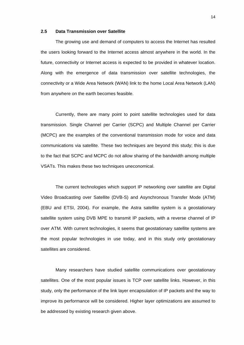
towards the satellite. The Figure 2.1 below illustrates the DVB-S topology.
17
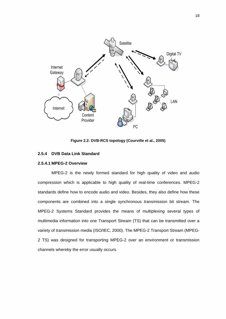
2.5.3 Digital Video Broadcasting-Return Channel Satellite
DVB with Return Channel via Satellite (DVB-RCS) has been standardized
enabling full independency to the terrestrial network. DVB-RCS is a new standard
modified from DVB-S by adding an additional standard on creating an interactive return
channel using satellite. Figure 2.3 shows the DVB-RCS topology. The DVB-RCS has a
broadcast channel in forward link and point to point (PPP) channel in return link.
In a DVB family, data can be transferred by using fixed size MPEG-2 Transport
Stream to carry packetized data in the forward link. Meanwhile, in the case of the DVB-
RCS system, different type of encapsulation schemes can be used on the return links
to transport the packet. On DVB-RCS links, either MPE/MPEG-2 TS or AAL5/ATM can
be used.
Figure 2.1: DVB-S topology (Ong et al., 2005)
18
2.5.4 DVB Data Link Standard
2.5.4.1 MPEG-2 Overview
MPEG-2 is the newly formed standard for high quality of video and audio
compression which is applicable to high quality of real-time conferences. MPEG-2
standards define how to encode audio and video. Besides, they also define how these
components are combined into a single synchronous transmission bit stream. The
MPEG-2 Systems Standard provides the means of multiplexing several types of
multimedia information into one Transport Stream (TS) that can be transmitted over a
variety of transmission media (ISO/IEC, 2000). The MPEG-2 Transport Stream (MPEG-
2 TS) was designed for transporting MPEG-2 over an environment or transmission
channels whereby the error usually occurs.
Figure 2.2: DVB-RCS topology (Courville et al., 2005)
19
2.5.4.2 MPEG-2 TS
Traditionally the MPEG-2 TS is designed to carry multiple Programs in a stream
that contains compressed video and audio data (Yoshimura, 2002). For the video data
compression, the scenes with a lot of motion in pictures are normally encoded with a
higher bit rate than scenes with less motion. The compression causes a variable data
rate of each TV program. Bursty and fluctuating characteristic of variable-bit-rate (VBR)
of compressed video traffic requires allocation of extra bandwidth to achieve delay and
bit-error-rate (BER) requirements of DVB (Yilmaz, 2002).
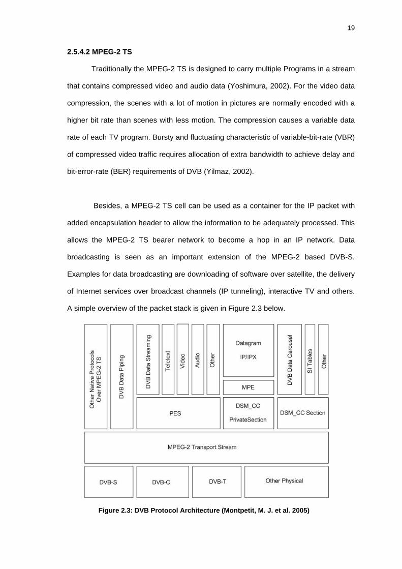
Besides, a MPEG-2 TS cell can be used as a container for the IP packet with
added encapsulation header to allow the information to be adequately processed. This
allows the MPEG-2 TS bearer network to become a hop in an IP network. Data
broadcasting is seen as an important extension of the MPEG-2 based DVB-S.
Examples for data broadcasting are downloading of software over satellite, the delivery
of Internet services over broadcast channels (IP tunneling), interactive TV and others.
A simple overview of the packet stack is given in Figure 2.3 below.
Figure 2.3: DVB Protocol Architecture (Montpetit, M. J. et al. 2005)
20
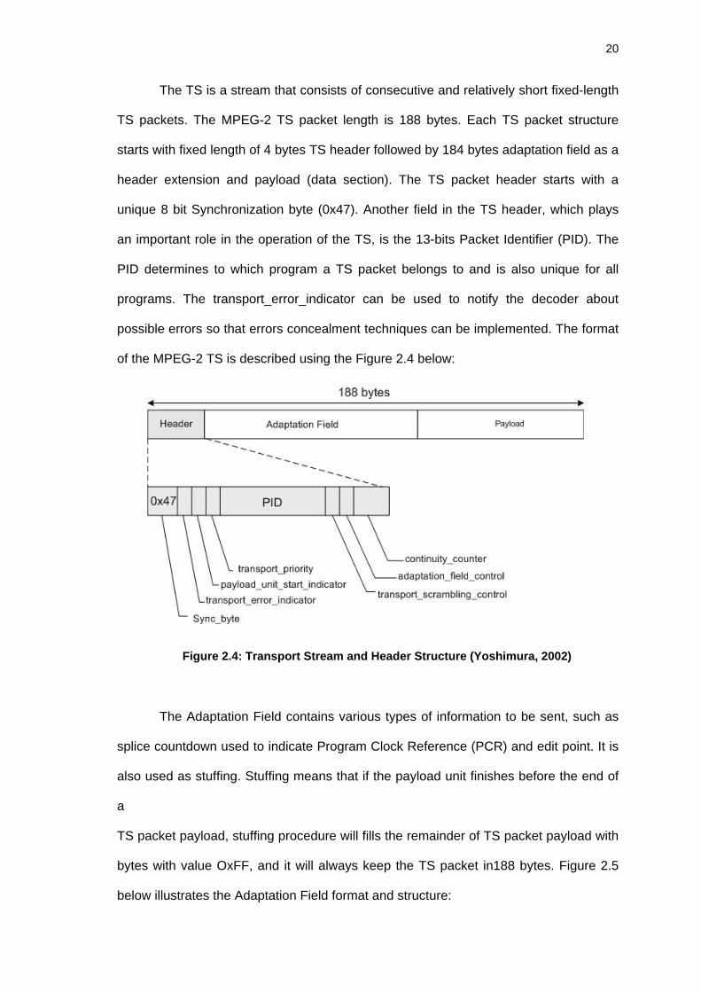
The TS is a stream that consists of consecutive and relatively short fixed-length
TS packets. The MPEG-2 TS packet length is 188 bytes. Each TS packet structure
starts with fixed length of 4 bytes TS header followed by 184 bytes adaptation field as a
header extension and payload (data section). The TS packet header starts with a
unique 8 bit Synchronization byte (0x47). Another field in the TS header, which plays
an important role in the operation of the TS, is the 13-bits Packet Identifier (PID). The
PID determines to which program a TS packet belongs to and is also unique for all
programs. The transport_error_indicator can be used to notify the decoder about
possible errors so that errors concealment techniques can be implemented. The format
of the MPEG-2 TS is described using the Figure 2.4 below:
The Adaptation Field contains various types of information to be sent, such as
splice countdown used to indicate Program Clock Reference (PCR) and edit point. It is
also used as stuffing. Stuffing means that if the payload unit finishes before the end of
a
TS packet payload, stuffing procedure will fills the remainder of TS packet payload with
bytes with value OxFF, and it will always keep the TS packet in188 bytes. Figure 2.5
below illustrates the Adaptation Field format and structure:
Figure 2.4: Transport Stream and Header Structure (Yoshimura, 2002)
21
Over the years, there are many encapsulation methods have been used to
transmit data over DVB.
1. Data Streaming
The IP packet is encapsulate into PES packets by mapping an IP packet into a
PES packet payload.
Figure 2.5: Adaptation Field Structure (Yoshimura, 2002)
Figure 2.6 Functional Block Diagram of a DVB System (EBU and ETSI, 1997a)
22
2. Data Piping
Data packet encapsulate directly into MPEG-2 TS packet, this mode can be
used to transport ATM/AAL5 over MPEG-2 TS.
3. Multi-protocol Encapsulation
IP packets encapsulate into Digital storage medium–command and control table
section packet.
4. Unidirectional Lightweight Encapsulation
IP packet encapsulate directly into MPEG-2 TS packet, which is also known as
ULE.
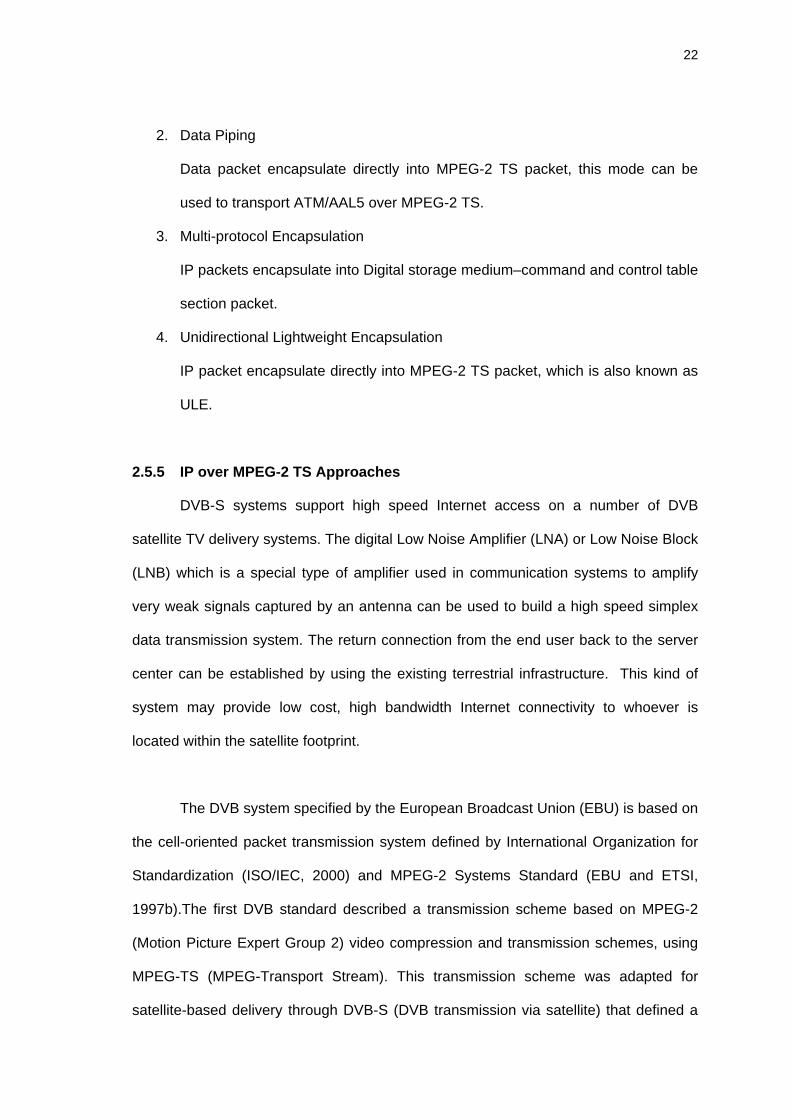
2.5.5 IP over MPEG-2 TS Approaches
DVB-S systems support high speed Internet access on a number of DVB
satellite TV delivery systems. The digital Low Noise Amplifier (LNA) or Low Noise Block
(LNB) which is a special type of amplifier used in communication systems to amplify
very weak signals captured by an antenna can be used to build a high speed simplex
data transmission system. The return connection from the end user back to the server
center can be established by using the existing terrestrial infrastructure. This kind of
system may provide low cost, high bandwidth Internet connectivity to whoever is
located within the satellite footprint.
The DVB system specified by the European Broadcast Union (EBU) is based on
the cell-oriented packet transmission system defined by International Organization for
Standardization (ISO/IEC, 2000) and MPEG-2 Systems Standard (EBU and ETSI,
1997b).The first DVB standard described a transmission scheme based on MPEG-2
(Motion Picture Expert Group 2) video compression and transmission schemes, using
MPEG-TS (MPEG-Transport Stream). This transmission scheme was adapted for
satellite-based delivery through DVB-S (DVB transmission via satellite) that defined a
23
series of options for sending MPEG-TS packets over satellite links which is commonly
used for Digital TV today. The first generation of DVB-S was not intended to carry IP
data since it was designed to exclusively transport MPEG-2 TS packets. The transport
of IP datagrams over DVB-S was later introduced by encapsulating them into MPEG-2
TS packets.
In order to support such features, a numbers of manufacturers supply DVB-S
receiver card with data capability and gateways at the uplink station to packetize the
data to be sent. In an effort to standardize these services, the DVB specification has
identified several different application areas with different requirements for the data
transport, which was been explained in previous sections (Section 2.5.4). In the
following section, 3 encapsulation methods will be explained in details.
1. Multi-protocol encapsulation ( using Multi-Protocol Encapsulation) (MPE)
2. Data piping ( using Unidirectional Light Encapsulation) (ULE)
3. Data piping ( using ATM/AAL5) (ATM/AAL5)
Figure 2.7: Internet Delivery Using DVB
24
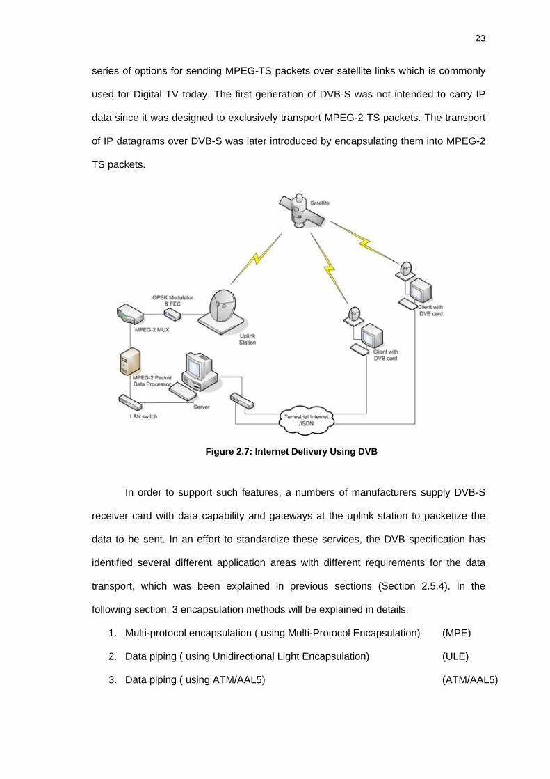
2.5.5.1 Multi-Protocol Encapsulation (MPE)
The most common method employed to carry Internet Protocol is MPE. The
DVB MPE (EBU and ETSI, 2004) format is compliant with the Digital Storage Media
Command and Control (DSM_CC) section format for private data. In order to carry IP
packets in the MPEG-2 stream, there is a section named datagram section which
defined by DSM-CC to support any type of OSI layer 3 networking protocol. However
DVB has optimized the section format to make it easier to use MPE with IP datagrams.
Figure 2.8 illustrates the packet format of MPE encapsulation method.
The MPE method provides a mechanism for transporting data network protocols
on top of the MPEG-2 Transport Streams in DVB networks. In addition, it also can be
used for transporting any kind of OSI layer 3 networking protocol by using the
LLC/SNAP encapsulation. It supports unicast, multicast and broadcast. Since the
research focuses on IP only, the LLC/SNAP encapsulation for MPE won’t be examined
further in any details. In MPE, it contains several MAC addresses fields, these 48-bit
MAC addresses are used for addressing receivers. However, DVB does not specify
how these MAC addresses are allocated to the receivers.
Figure 2.8: MPE Packet Format (Collini-Nocker and Fairhurst, 2004)


![AP3150 Multichannel IP Voice Broadcasting Server [호환 모드] Adi Cd f APMP3 2M d l AP3150 Multichannel IP Voice Broadcasting Server APOS Service Features • Voice Codec for AP-AUDIO4](https://static.documents.pub/doc/80x56/610556d5f397a435bc5b554a/ap3150-multichannel-ip-voice-broadcasting-server-eeoe-adi-cd-f-apmp3.jpg)


