Ensuring reservoir safety into the future. Thomas Telford, London, 2008 Ulley Reservoir and high velocity spillway flows J L HINKS , , Halcrow Group Limited PJ MASON, Montgomery Watson Harza JR CLAYDON, Independent Consultant SYNOPSIS. In the small hours of Tuesday 26 June, 2007 Rotherham Metropolitan Borough Council requested the evacuation of areas downstream of Ulley Dam and the closure of the M1 motorway because of fears about the safety of the dam. The danger arose because of the failure of the masonry walls of one of the original spillways at the dam during a flood with a return period of about 200 years. This paper discusses the background to the incident, the problems associated with high velocity flows in masonry spillways, the handling of the emergency and plans for the restoration of the dam. INTRODUCTION Ulley reservoir is located about 5 km to the south-east of the town of Rotherham in Yorkshire. The dam, which is earthfill with a puddle clay core, was completed in 1873 and was originally used for water supply. In 1986 it was sold by the Yorkshire Water Authority to Rotherham Metropolitan Borough Council for £1 plus outstanding debts. Since then it has formed the centrepiece of the Council’s Ulley Country Park. 92.4 mm of rain (measured at the Maltby raingauge) fell on 24 and 25 June, 2007. This caused flooding in the Borough, most notably at Catcliffe, and also led to significant spill from Ulley reservoir. At 19.00 on Monday, 25 June the Manager of the Country Park visited the dam and decided that there was a risk of erosion adjacent to the south bywash channel that might endanger the dam. The site was then visited the same evening by officials of the council and by the Supervising Engineer. At 01.20 on Tuesday 26 June the Chief Executive of the council requested that areas downstream be evacuated and that the M1 motorway be closed in both directions downstream of the dam. The total number of people evacuated was about 1,000 although it is not possible to say exactly how
Transcript
Ensuring reservoir safety into the future. Thomas Telford, London, 2008
Ulley Reservoir and high velocity spillway flows
J L HINKS,, Halcrow Group Limited
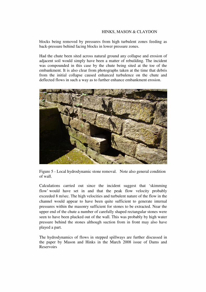
PJ MASON, Montgomery Watson Harza
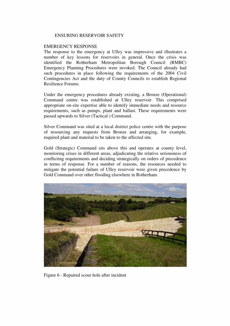
JR CLAYDON, Independent Consultant
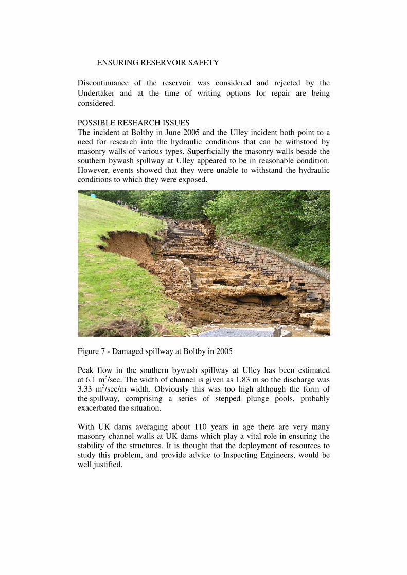
SYNOPSIS. In the small hours of Tuesday 26 June, 2007 Rotherham
Metropolitan Borough Council requested the evacuation of areas
downstream of Ulley Dam and the closure of the M1 motorway because of
fears about the safety of the dam. The danger arose because of the failure of
the masonry walls of one of the original spillways at the dam during a flood
with a return period of about 200 years.
This paper discusses the background to the incident, the problems associated
with high velocity flows in masonry spillways, the handling of the
emergency and plans for the restoration of the dam.
INTRODUCTION
Ulley reservoir is located about 5 km to the south-east of the town of
Rotherham in Yorkshire. The dam, which is earthfill with a puddle clay
core, was completed in 1873 and was originally used for water supply. In
1986 it was sold by the Yorkshire Water Authority to Rotherham
Metropolitan Borough Council for £1 plus outstanding debts. Since then it
has formed the centrepiece of the Council’s Ulley Country Park.
92.4 mm of rain (measured at the Maltby raingauge) fell on 24 and
25 June, 2007. This caused flooding in the Borough, most notably at
Catcliffe, and also led to significant spill from Ulley reservoir. At 19.00 on
Monday, 25 June the Manager of the Country Park visited the dam and
decided that there was a risk of erosion adjacent to the south bywash
channel that might endanger the dam. The site was then visited the same
evening by officials of the council and by the Supervising Engineer.
At 01.20 on Tuesday 26 June the Chief Executive of the council requested
that areas downstream be evacuated and that the M1 motorway be closed in
both directions downstream of the dam. The total number of people
evacuated was about 1,000 although it is not possible to say exactly how
ENSURING RESERVOIR SAFETY
many of these were evacuated as a result of the flooding already being
experienced and how many were evacuated as a precaution against the
possible failure of Ulley dam.
Responsibility for the enforcement of the Reservoirs Act, 1975 in England
and Wales passed to the Environment Agency on 1 October 2004.
Since then, their Reservoir Safety Section based in Exeter, have been active
in promoting various initiatives aimed at improving reservoir safety. One of
these is their Post-Incident reporting system for UK dams which has been
developed on their behalf by Halcrow Group Limited. The final report
setting up the system was submitted in February, 2007.
Under the relatively new Post-Incident reporting system the Environment
Agency requested Jonathan Hinks and Peter Mason to prepare a review
report on the Ulley incident with the objective of ensuring that any
appropriate lessons were learned by those responsible for reservoir safety in
the UK. This report, which was submitted in November 2007, did not cover
future actions to be taken to ensure the safety of the reservoir. These matters
were addressed in a report under Section 10 of the Reservoirs Act prepared
by Mr.J.Claydon (Independent All Reservoirs Panel Engineer engaged by
Ove Arup & Partners Ltd. as a sub-consultant).
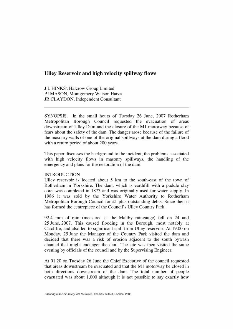
Figure 1 - Works in progress filling scour hole
BACKGROUND
Ulley dam has a puddle clay core, a crest length of 205 m and a maximum
height of 16 m. It impounds a reservoir with a capacity of 580,000 m3.
HINKS, MASON & CLAYDON
The catchment area to the north-east, east and southeast is 11.86 km2.
.
The reservoir has a surface area of 0.12 km2.
The dam is located on sandstones of the Middle Coal Measures of the
Upper Carboniferous period. Mine workings are known to have taken place
in the area in at least eight seams. During the twentieth century mining
within the area of influence of the reservoir is known to have taken place
as follows:
Barnsley Seam in 1927 at a depth of 434 m
High Hazel Seam in 1953 at a depth of 357m
Thorncliffe Seam in 1964 at a depth of 677 m
Wathwood seam in 1967 at a depth of 300 m
In each of the above seams an area of coal is said to have been left
unworked to protect the dam from the worst effects of subsidence, although
the design of such pillars may not in all cases have been based on present
day understanding of the real effects of mining subsidence.
In addition to the above an unspecified seam was mined in 1935. A proposal
to purchase a pillar in this seam was turned down by Rotherham Council
who preferred to let the dam settle before building the new spillway in 1943.
There was damage to the scour tunnel and pipe in 1968 which may possibly
have been associated with mining in the Wathwood Seam the previous year.
However this is not certain since a pillar is believed to have been purchased
in the Wathwood Seam.
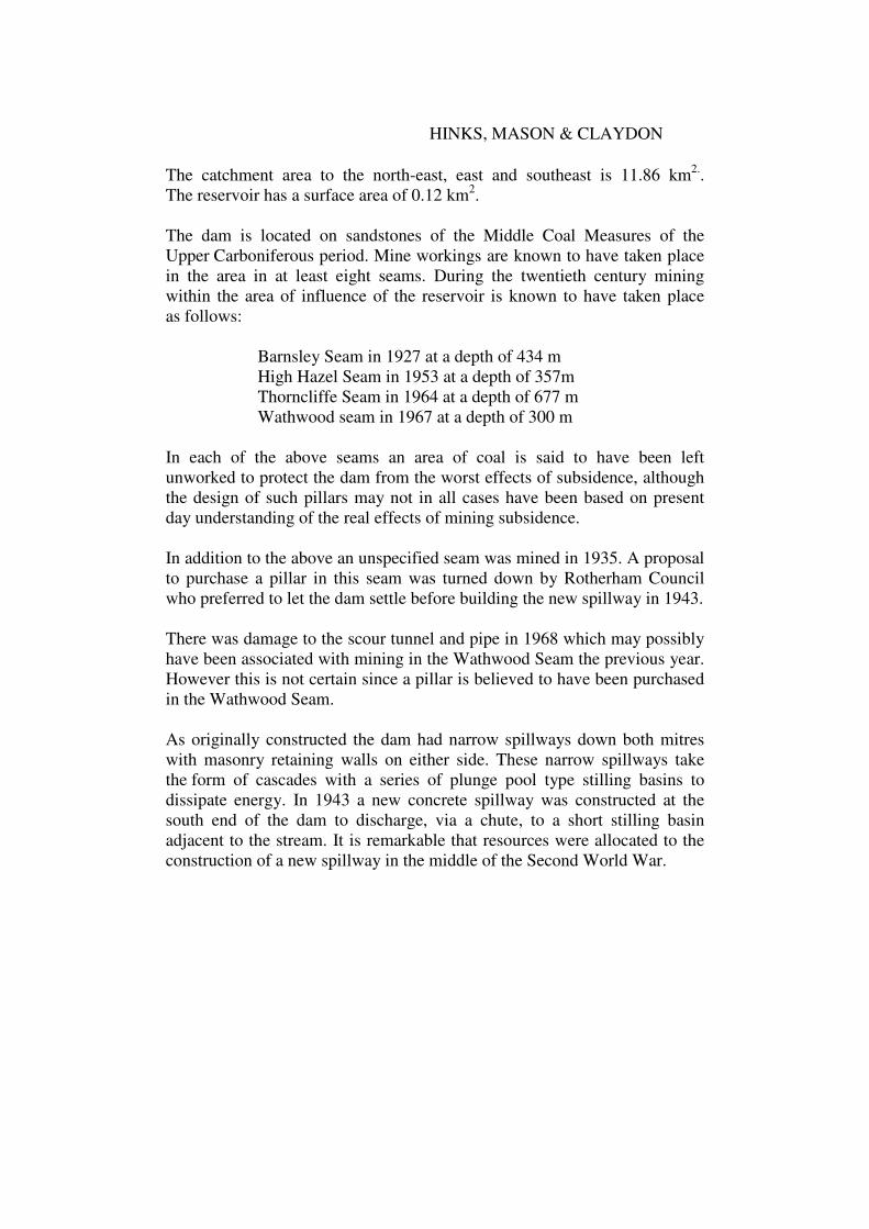
As originally constructed the dam had narrow spillways down both mitres
with masonry retaining walls on either side. These narrow spillways take
the form of cascades with a series of plunge pool type stilling basins to
dissipate energy. In 1943 a new concrete spillway was constructed at the
south end of the dam to discharge, via a chute, to a short stilling basin
adjacent to the stream. It is remarkable that resources were allocated to the
construction of a new spillway in the middle of the Second World War.
ENSURING RESERVOIR SAFETY
Figure 2 - Flow down 1943 spillway and original south spillway during
the incident. Original south spillway is on extreme right of photograph.
The hydraulics at the south end of the dam are complicated with water
entering two spillways at different levels, in one case round a sharp right-
angled bend.
2006 survey (m AOD )
Previous TWL ( southern bywash ) 51.75
Morthern Weir 53.56
1943 weir 52.98
Peak WL in 2007 flood 53.55
It will be seen from the above that the lowest of the three weirs was that
at the top of the southern bywash channel and that the 1943 weir was
1.23 m higher. The Morthern (sic) weir was still higher and did not actually
discharge any significant amount of water in the June 2007 flood.
Total outflow in the spillways during the incident is thought to have been
about 10.1 m3/sec (6.1 m
3/sec down the old masonry channel and 4.0 m
3/sec
down the 1943 spillway). The table below suggests that the flood had a
return period of about 200 years.
The following table is based on calculations by Jeremy Benn Associates of
Skipton presented in their report of November 2006. Adjustments have,
however, been made to the assumed discharge coefficients and the results
related to the datum used for the 2006 survey.
HINKS, MASON & CLAYDON
Return Period (Years) Peak Water
Level
(m AOD )
Peak
Outflow
(m3/sec)
Wave
freeboard
(m)
FEH 150 year 53.25 7.00 1.95
FEH 1,000 year 53.61 14.44 1.59
FSR 1,000 year 53.47 11.24 1.73
FSR 10,000 year 53.98 26.32 1.22
FEH PMF Summer 54.95 71.56 0.25
FEH PMF winter 54.69 57.99 0.51
The above figures show that the peak flow in the incident was only about
14 % of the PMF and 38 % of the 10,000 year outflow.