34
USER MANUAL V2.1 Ultimaker 2 MAKES EASY, EVEN EASIER

USER MANUALV2.1
Ultimaker2
MAKES EASY, EVEN EASIER

2

3
1. ULTIMAKER 2 4
Ultimaker 2 at a glance 5
Specifications 7
2. GET STARTED 8
Unboxing 9
Installation 11
First use 13
3. THE BASICS 16
Changing filament 17
Bed leveling 18
Cura software 19
Using glue 20
Display and controller 21
4. MAINTENANCE 22
The glass plate 23
The feeder 24
Lubricating the axes 25
Atomic Method 26
5. HELP & SUPPORT 28
Troubleshooting 29
Support 31
Safety and compliance 32
TABLE OF CONTENTS

4
ULTIMAKER 2
This user manual is designed to help you start your Ultimaker 2 experience. Learn
everything about using your Ultimaker 2 by following the instructions in this user
manual and experience how easy it is to produce great quality prints.
You might be familiar with other types of Ultimakers or 3D printers. It is however
essential that you read this manual carefully in order to make the most out of your
Ultimaker 2.
1

5
1 32
6
54
7
8
9
ULTIMAKER 2 AT A GLANCE
Display
SD card slot
Push/rotate button
1
2
3
Build plate
Build plate clamps
Build plate screws
4
5
6
Print head
Bowden tube
Print head cable
7
8
9
Feeder
Spool holder
Power socket
10
11
12
USB socket
Power switch
13
14

6
12 13 14
10
8
9
11

7
Printing
Print technology Fused Filament Fabrication
Build volume 223 mm / 223 mm / 205 mm
Layer resolution Fast: 200 micron (0.2 mm)
Normal: 100 micron (0.1 mm)
High: 60 micron (0.06 mm)
Ulti: 40 micron (0.04 mm)
Positioning precision 12.5 micron / 12.5 micron / 5 micron
Filament diameter 2.85 mm
Nozzle diameter 0.4 mm
Print speed 30 mm/s - 300 mm/s
Travel speed 30 mm/s - 350 mm/s
Software
Supplied software Cura - Official Ultimaker Software
File types STL / OBJ / DAE / AMF
Supported OS Windows / Mac / Linux
Electrical
AC Input 100 - 240 V
Approx. 1.4 AMPS
50 - 60 Hz
221 Watt max.
Connectivity Stand-alone SD card printing
Physical dimensions
Desktop space 357 mm / 342 mm / 388 mm
Shipping dimensions 400 mm / 400 mm / 550 mm
Weight 11.2 kg
Shipping weight 18.0 kg
Temperature
Ambient operation temperature 15 - 32 °C
Storage temperature 0 - 32 °C
Nozzle operation temperature 180 - 260 °C
Heated bed operation temperature 50 - 100 °C
Sound
Average operational noise 49 dBA
CAUTION: The Ultimaker 2 generates high temperatures and has hot moving parts that can cause injury. Never
reach inside of the Ultimaker 2 while it is in operation. Always control the Ultimaker 2 with the button at the front or
with the power switch at the back. Allow the Ultimaker 2 to cool down for 5 minutes before reaching inside.
CAUTION: When opening the Ultimaker 2 for service, ensure that the power supply is turned off and the power
cable is disconnected from the wall socket.
CAUTION: Only use the power supply that came with your Ultimaker 2.
SPECIFICATIONS

8
GET STARTED
Now your Ultimaker 2 has arrived you’re ready to unpack it and set it up! Carefully
unpack your Ultimaker 2 and set it up according to the instructions on the next
pages.
When you use your Ultimaker 2 for the first time, it will guide you through some
steps to set it up and calibrate it. Follow the bed leveling and filament loading steps
carefully in order to set up your Ultimaker 2 correctly.
2

9
The Ultimaker 2 comes in reusable, durable packaging that has been specially designed to protect your Ultimaker 2 in
transport. To properly unpack your Ultimaker 2, please follow the steps described below.
START UNBOXING
After having opened the cardboard box in which your Ultimaker 2 was delivered the unboxing can begin. Start
unpacking by taking the Ultimaker 2 out of the cardboard box. You can best do this by carrying the belt and holding the
cardboard box while lifting the Ultimaker 2.
OPEN IT UP
When the Ultimaker 2 has been taken out of the box you can loosen the belt that’s placed around the foam packaging.
This allows you to take out the Accessory box, in which you will find the quick start guide and accessories.
REMOVE THE FOAM PACKAGING
In the foam part at the front side of your Ultimaker 2 you will find a spool with PLA filament and a test print done on your
Ultimaker 2. Take these out and put them aside. Open up the complete packaging by removing the two foam parts at
the front and the back side. Now you can take out the Ultimaker 2 and place it on your desk. Make sure you hold the
Ultimaker 2 on the frame and don’t hold it on the belts or axes while carrying it.
REMOVING PROTECTION
There is some packaging material under the build plate. You can easily remove it by lifting the build plate with your
hands. At last, cut the zip tie with which the print head is secured and your Ultimaker 2 is ready to use!
UNBOXING
10
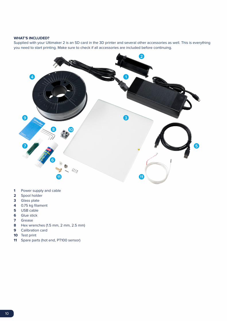
WHAT’S INCLUDED?Supplied with your Ultimaker 2 is an SD card in the 3D printer and several other accessories as well. This is everything
you need to start printing. Make sure to check if all accessories are included before continuing.
Power supply and cable
Spool holder
Glass plate
0.75 kg filament
USB cable
Glue stick
Grease
Hex wrenches (1.5 mm, 2 mm, 2.5 mm)
Calibration card
Test print
Spare parts (hot end, PT100 sensor)
1
2
3
4
5
10
6
8
7
11 11
1
2
3
4
5
6
7
8
9
10
11
9

11
SPOOL HOLDER
The first step of setting up your Ultimaker 2 is attaching the spool holder at the back side of the Ultimaker 2. Make sure
to install the spool holder as described below.
1. Take the spool holder and insert the top part in the hole at the back of the Ultimaker 2.
2. Push the spool holder down until it snaps into place.
GLASS PLATE
The glass plate is the print surface for prints on your Ultimaker 2. It will be installed the following way.
1. Open up the two build plate clamps at the front side of the build plate with a hex wrench.
2. Gently slide the glass plate on the build plate and make sure it snaps into the build plate clamps at the back.
3. Close the two build plate clamps at the front to secure the glass plate.
CAUTION: The build plate clamps can be sharp, therefore it is advised to use on of the hex wrenches for opening
them.
INSTALLATION

12
POWER SUPPLY
To finish the installation the power supply will be connected. Before connecting it, make sure the power switch is in the
“off” position.
1. Connect the power cable to the power brick.
2. Plug the power cable in the wall socket and connect the other side to the Ultimaker 2. The flat side of this cable
needs to point upwards.

13
After finishing the installation it’s time to turn the Ultimaker 2 on!
CONTROL
The display at the front side of the Ultimaker 2 shows all the necessary information for setting up and using your
Ultimaker 2. You can navigate through menus by rotating and/or pushing the button at the right side of the display.
Rotating allows you to select or control an action; by pushing you can confirm an action. When pushing the button you
will hear a “beeping” sound to confirm the action. A blinking button means the Ultimaker 2 is waiting for user input.
BED LEVELING
After the “Welcome” screen, the Ultimaker 2 will guide you through some steps for calibrating the build plate. For
printing it is very important that the first layer is nicely squished into the glass plate and sticks well to it. If the distance
between the nozzle and build plate is too big, your print won’t stick properly to the glass plate. On the other hand, if the
nozzle is too close to the build plate it can prevent the filament from extruding from the nozzle.
NOTE: If you don’t see the configuration wizard, navigate to “Maintenance” > “Advanced” and confirm for a Factory
reset. You can use this function at any time.
Before the bed leveling can be done, the Ultimaker 2 will first do the “homing”. This means that it will move the print
head to the left back corner and the build plate towards the bottom, in order to set the origin point. After this, you can
follow the steps below for leveling the build plate.
1. The first step is to roughly level the build plate by rotating the button at the front of your Ultimaker 2 until there is
approximately 1 mm distance between the nozzle and build plate. The measurement here is not critical, just make
sure that the nozzle is close to the build plate without touching it.
2. Next, a rough adjustment will be done on the front left and right side by turning the build plate screws. Turning
the build plate screws to the left means that the build plate will get closer to the nozzle. Again there should be a
distance of approximately 1 mm between the nozzle and build plate.
3. The last step will be fine-tuning of the build plate with the “calibration card”. Place the calibration card in between
the nozzle and build plate on all 3 points and adjust the build plate screws until you feel slight friction when moving
the card.
NOTE: Don’t push on the build plate while fine-tuning with the calibration card; this will lead to inaccuracies.
FIRST USE

14
LOADING FILAMENT
After bed leveling it is time to further prepare the Ultimaker 2 for the first print by loading filament.
1. Before loading the filament, the spool with filament has to be placed on the spool holder. Make sure to put it with
the filament in counter-clockwise direction, so that the filament can enter the feeder from the bottom. It’s also
recommended to straighten the filament a bit so it can easily enter the feeder.
2. Next, wait a minute while the print head is heating up. By heating it up we ensure that the filament is being melted
when it goes through the nozzle.
3. Take the end of the filament, insert it into the bottom of the feeder and push it until the filament is being grabbed
by the knurled wheel. This may require some force. Once the knurled wheel has grabbed the filament, it will slowly
move it further into the bowden tube.
4. Wait till the filament reaches the first black bowden tube clip and then press the button to continue. The Ultimaker 2
will automatically load the filament through the bowden tube, into the print head.
Now you just have to wait until the filament is coming out of the nozzle. You may notice a ticking sound at the feeder;
this is nothing to worry about. If necessary you can manually push the filament in order to get it through the nozzle with
a bit more force.
CAUTION: Make sure to not touch the nozzle/hot end during this procedure as it will become hot.
NOTE: Don’t be surprised if the filament that initially comes out of the nozzle is not the color you expect. There is
probably some residue from the test print left in the nozzle. Wait until you see the color of the filament that
you loaded coming out of the nozzle.

15
START A PRINT
Now the build plate has been leveled and filament loaded you’re ready to start your first print! We’ve placed some print
files on the SD card to start with. Simply select one of the files and press the button to start.
After a print file has been chosen the Ultimaker 2 will prepare itself by homing the print head and build plate and
heating up the build plate and nozzle. Please note that this can take up to 5 minutes.
While printing, the display will show the progress of the print and the remaining time for completion. When the print has
finished, wait for the build plate to cool down and grab the print from the build plate.
NOTE: For good platform adhesion it is recommended to apply a thin layer of glue to the glass plate. Therefore you
can use the glue stick delivered with the Ultimaker 2. Look at page 20 for detailed instructions.
CAUTION: Don’t touch the print head/nozzle while it is heating, printing or cooling down. Temperatures can reach
up to 260°C.

16
THE BASICS
This chapter will explain you more about the basic procedures for using your
Ultimaker 2. You will for example find information on changing filament and bed
leveling, but also the use of our software Cura is explained here.
3

17
If you want to switch between different (colors of) materials you first need to unload the filament that is already in the
Ultimaker 2, after which you can insert the new filament.
REMOVE OLD FILAMENT
Removing the filament can simply be done by following the steps below.
1. Access the material change menu on your Ultimaker 2 by going to “Material” > “Change”.
2. Wait a minute while the print head is heating up. By heating it up we ensure that the filament is being melted before
retracting it from the nozzle.
3. When the nozzle is hot, the Ultimaker 2 will automatically start turning the feeder wheel, through which the filament
will be rewind completely. If the filament doesn’t come out of the feeder completely you can simply pull it out by
hand.
Note: Make sure the feeder is free of any small pieces of filament before inserting new material. You can remove
small pieces of filament with tweezers. For easier access you can loosen the bowden tube at the top of the feeder by
removing the clamp clip, pressing down the tube coupling collet and pulling out the bowden tube.
LOAD NEW FILAMENT
After removing the filament you can start loading the new filament in the same way as done during the first setup of
your Ultimaker 2. Make sure the old spool with filament is removed from the spool holder and the new one is placed.
1. Take the end of the filament, insert it into the bottom of the feeder and push it until the filament is being grabbed
by the knurled wheel. This may require some force. Once the knurled wheel has grabbed the filament, it will slowly
move it further into the bowden tube.
2. Wait till the filament reaches the first black bowden tube clip and then press the button to continue. The Ultimaker 2
will automatically load the filament through the bowden tube, into the print head.
Now you just have to wait until the filament is coming out of the nozzle. You may notice a ticking sound at the feeder;
this is nothing to worry about. If necessary you can manually push the filament in order to get it through the nozzle with
a bit more force.
CHANGING FILAMENT

18
As explained in chapter 2 the first layer of a print is very important. Therefore regular bed leveling is advised. Always
re-level the build plate when you notice that the plastic is not equally placed on the glass plate. After transportation of
your Ultimaker 2 it is also advised to re-level the build plate to ensure your 3D prints stuck well to the build plate.
BED LEVELING PROCEDURE
The basic steps for bed leveling are described below.
1. Go to “Maintenance” > “Build plate” to start the bed leveling process on your Ultimaker 2.
2. Wait for the Ultimaker 2 to do its homing procedure and continue when the print head is in the center at the back of
the build plate.
3. The first calibration step is to roughly level the build plate by rotating the button at the front of your Ultimaker 2 until
there is approximately 1 mm distance between the nozzle and build plate. The measurement here is not critical, just
make sure that the nozzle is close to the build plate without touching it.
4. Next, the same adjustment will be done on the front left and right side, but this time by turning the build plate
screws. If you turn them to the left the build plate will get closer to the nozzle.
5. The last step will be fine-tuning of the build plate with the “calibration card”. If necessary further adjustment can
be done by turning the build plate screws. Place the calibration card in between the nozzle and build plate on all 3
points and adjust the build plate screws until you feel slight friction when moving the card.
NOTE: Don’t push on the build plate while fine-tuning with the calibration card; this will lead to inaccuracies.
BED LEVELING

19
For the Ultimaker 2, we recommend our free Cura software to prepare your 3D print files. Cura quickly and accurately converts 3D models into 3D print files within seconds, showing you a preview of the print so you can be sure everything
is as you would like it to be.
INSTALLATION
The Cura software can be found at www.ultimaker.com/software. After downloading, open the installer and run the
installation wizard to complete the installation. When opening Cura for the first time, you will be asked to select your 3D
printer; select the Ultimaker 2. No other configuration is required and you can directly start using Cura.
USING CURA
The basic process of converting a 3D model to a print file in Cura is described below.
1. Load a 3D model (STL, OBJ, DAE or AMF file) into Cura via the “Load” button.
2. Choose your desired settings and wait for Cura to slice the model.
3. When Cura has converted the file you can save the print file (GCode) via the “Save” button. If the SD card has been
inserted it will directly save the file to the SD card.
4. Remove the SD card from your computer - make sure to safely remove it - and insert it in your Ultimaker 2 to start
printing.
When using Cura for the first time you will see the “Quickprint” profiles. This is perfect for beginners, but when you’re
a more experienced user and want to have more control over the print settings you can also switch to the “Advanced”
mode. For more information on using Cura you can visit the Cura support pages: www.ultimaker.com/support/software
UPDATING FIRMWARE
Regularly a new Cura version is released, including a new firmware version as well. Make sure to install the latest
version of Cura and firmware once available in order to stay up to date. The latest version of Cura can always be found
at www.ultimaker.com/software.
In order to install the latest firmware on your Ultimaker 2, please take the following steps:
1. Connect the Ultimaker 2 to your computer with the USB cable.
2. Attach the power supply and turn the Ultimaker 2 on.
3. Start Cura and go to “Machine” > “Install default firmware” (make sure the Ultimaker 2 is selected in the “Machine”
menu). Cura will now automatically upload the latest firmware to your Ultimaker 2.
CURA SOFTWARE
20
Although the heat of heated bed already takes care of the adhesion of your print to the glass plate, this is not always
enough. For even better adhesion it is in some cases desired to also use glue on the glass plate.
WHEN TO USE GLUE?
The use of glue usually depends on the material you’re using and the size and shape of the model.
For ABS and CPE we recommend to always use glue, because these materials have more “warping”. This means that
the plastic will curl up. Warping basically happens because of the properties of the plastic. Plastics have the tendency to
shrink when cooling down fast (some plastics more than others), which could eventually lead to your print curling up (at
the corners). Since ABS and CPE have a relatively big shrinkage you will need glue to prevent it from warping.
PLA on the other hand, has a much lower shrinkage and thus less warping. Because of this it’s often possible to print
PLA directly on the glass plate, without glue. In this case you need to make sure that the glass plate is completely free
from dust and oil though, because plastic won’t stick well to a greasy surface. There are however situations in which
glue on the glass plate is desired. If you want to print a model that has a big footprint, or with very thin parts at the
bottom it’s advised to use glue to prevent it from getting loose.
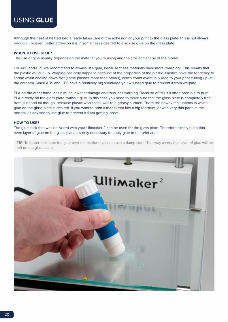
HOW TO USE?
The glue stick that was delivered with your Ultimaker 2 can be used for the glass plate. Therefore simply put a thin,
even layer of glue on the glass plate. It’s only necessary to apply glue to the print area.
TIP: To better distribute the glue over the platform you can use a damp cloth. This way a very thin layer of glue will be
left on the glass plate.
USING GLUE

21
When turning on your Ultimaker 2, you will always see the Ultimaker logo first after which you will go to the main menu.
The main menu offers three options: PRINT, MATERIAL and MAINTENANCE.
The “Print” menu simply allows you to select one of the print files from the SD card and will automatically start the print
after that.
MATERIAL
In the “Material” menu you can either change the filament on your Ultimaker 2 or change the settings of material
profiles. When selecting “Change” the Ultimaker 2 will start the procedure as described in chapter 3. In the “Settings”
menu you can select material profiles and change their settings in the “Customize” menu.
MAINTENANCE
The “Maintenance” menu offers various options. By selecting “Build plate” you will be guided through the bed leveling
steps. In the “Advanced” menu several options can be selected in order to manually do certain actions or change
machine settings. Below a short overview of all these options is shown.
• LED settings Change the settings of the LED lights in your Ultimaker 2
• Heatup nozzle Set custom temperature to manually heat up the nozzle
• Heatup buildplate Set a custom temperature to manually heat up the heated bed
• Home head Homes the head in the left back corner of the Ultimaker 2
• Lower buildplate Moves the build plate to the bottom of the Ultimaker 2
• Raise buildplate Moves the build plate to the top of the Ultimaker 2
• Insert material Heats up the nozzle after which you can insert filament
• Move material Heats up the nozzle after which you can use the scroll wheel to forward the material
• Set fan speed Set the speed of the two fans at the sides of the print head
• Retraction settings Customize the settings for retraction
• Version Shows the current firmware version on the Ultimaker 2
• Runtime stats Shows for how much time the Ultimaker 2 has been on and printing
• Factory reset A complete reset of your Ultimaker 2 through which you can completely recalibrate it
FINE-TUNING
The Ultimaker 2 also offers you the possibility to fine-tune settings during the printing process. This allows you to get
full control over the printing process and helps you achieving the best print results. You can do this by accessing the
“Tune” menu during printing. The Tune menu basically shows you the same settings as in the Advanced menu, which
means that you can change settings like for example the temperature and speed of printing. Furthermore, it is possible
to select “Pause”, after which you can change the filament in the middle of a print and resume again.
DISPLAY AND CONTROLLER

22
MAINTENANCE
In order to have a smoothly working Ultimaker 2 it is important to maintain it
correctly. In this chapter the most important maintenance tips are described. It is
recommended to read them carefully in order to achieve the best results with your
Ultimaker 2.
4

23
CLEANING THE GLASS PLATE
After a lot of printing, there sometimes can be too much excess glue stuck to the glass plate. This can cause an uneven
print surface and it is therefore recommended to clean the glass plate once in a while. When doing this, always make
sure that the Ultimaker 2 is turned off and build plate has cooled down.
1. Before taking out the glass plate, first manually move the build plate to the bottom of the Ultimaker 2. This way
damage on the print head or Z trapezoidal leadscrew is prevented.
2. Open up the build plate clamps at the front side by using a hex wrench.
3. Slide the glass plate to the front of the build plate until you can take it out of the Ultimaker 2.
4. For cleaning it is advised to use some warm water and to brush off any excess glue. If necessary you can also use
some soap to clean it.
5. The glass plate can simply be place back by sliding it onto the build plate until it snaps into the build plate clamps at
the back of the build plate. Close the build plate clamps at the front side by hand in order to secure it.
CAUTION: The glass plate is positioned on an electrical heating area, so make sure it is completely dry before
placing it back.
NOTE: In order to be sure about a successful next print we recommend to re-level the build plate after having
repositioned the glass plate.
GLASS PLATE
24
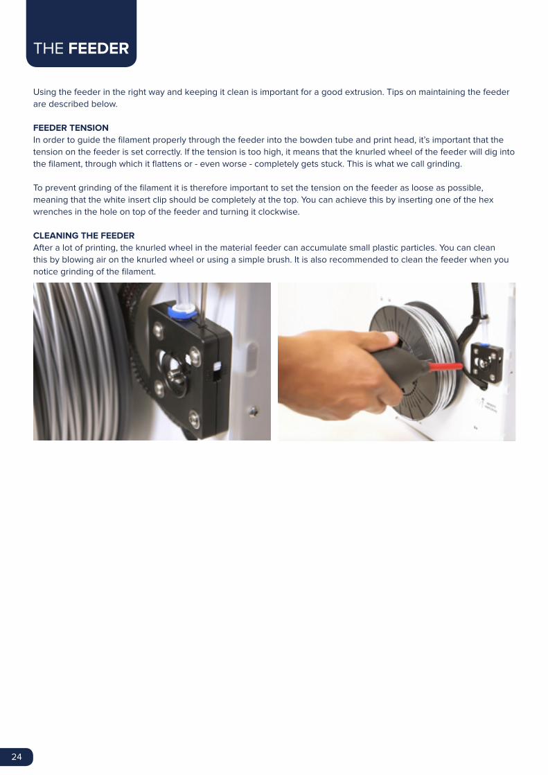
Using the feeder in the right way and keeping it clean is important for a good extrusion. Tips on maintaining the feeder
are described below.
FEEDER TENSION
In order to guide the filament properly through the feeder into the bowden tube and print head, it’s important that the
tension on the feeder is set correctly. If the tension is too high, it means that the knurled wheel of the feeder will dig into
the filament, through which it flattens or - even worse - completely gets stuck. This is what we call grinding.
To prevent grinding of the filament it is therefore important to set the tension on the feeder as loose as possible,
meaning that the white insert clip should be completely at the top. You can achieve this by inserting one of the hex
wrenches in the hole on top of the feeder and turning it clockwise.
CLEANING THE FEEDER
After a lot of printing, the knurled wheel in the material feeder can accumulate small plastic particles. You can clean
this by blowing air on the knurled wheel or using a simple brush. It is also recommended to clean the feeder when you
notice grinding of the filament.
THE FEEDER

25
To maintain your Ultimaker 2 correctly and keep it running smoothly it is recommended to lubricate the axes once in a
while.
X AND Y AXES
When you notice small ridges on the surfaces of your 3D printed objects or feel that the X and Y axes are dry it is
advised to put a single drop of sewing machine oil onto the X and Y axes. This will help your Ultimaker 2 running
smoothly. Sewing machine oil is not included in the Ultimaker 2 package, but we highly recommend to only use this for
lubricating the X and Y axes.
Z TRAPEZOIDAL LEADSCREW
Once every half year the Z trapezoidal leadscrew has to be lubricated with Magnalube. This is the green grease that
was delivered with your Ultimaker 2. Make sure to spread 10 drops of grease over the entire threaded rod. With your
next print the Ultimaker 2 will lubricate the axis itself by moving up and down.
NOTE: Magnalube should be applied to the Z trapezoidal leadscrew only; make sure to not put it on any of the other
axes.
LUBRICATING THE AXES

26
After a longer time of using your Ultimaker 2 you might notice some signs of “under extrusion”. This means that your
Ultimaker 2 can’t extrude enough plastic and is usually shown by very thin or missing layers in a print. In most cases, it
is caused by some dirt or carbonized material in the nozzle or another hot end part through which a (partial) blockage is
created. When under extrusion appears it is recommended to use the Atomic Method in order to clean the nozzle and
other hot end parts. Below, the process of this simple though very effective method is described.
NOTE: It is also advised to use the Atomic Method when switching from a material that needs a higher printing
temperature to one that uses a lower printing temperature in order to make sure any residue from the previous
filament is removed.
REMOVE THE FILAMENT
• Go to MATERIAL > CHANGE in order to remove the filament and instead of inserting new material, select CANCEL
• Keep the print head in the corner
REMOVE THE BOWDEN TUBE
• Remove the (blue or red) clamp clip
• Press down the tube coupling collet and pull the bowden tube out of the print head
HEAT UP AND PREPARATION
• Go to MAINTENANCE > ADVANCED > Heatup nozzle and set the temperature to 260 degrees
• Cut off approximately 20 cm of filament with a straight cut and try to straighten the filament as much as possible
• When the temperature is reached, insert the straightened piece of filament manually all the way down to the nozzle
• Push it slightly until either the new filament comes out of the nozzle or until the filament can’t be pushed any further
ATOMIC METHOD

27
REMOVE THE NEW FILAMENT
• Lower the temperature to 90 degrees (for PLA) or 110 degrees (for ABS)
• Once the temperature has been reached, pull the filament out with a quick, firm pull
• Check the color and shape of the tip of the filament; the goal is to have a clean, cone-shaped tip
• Repeat step 3 and 4 until the filament comes out without any residue and has a cone-like shape
RE-ASSEMBLY
• Insert the bowden tube through the tube coupling collet all the way down into the PTFE coupler
• Place the clamp clip around the tube coupling collet so that it secures the bowden tube

28
HELP & SUPPORT
There are a few printer specific issues that could show up while using your
Ultimaker 2. If you ever run into one of these issues, you can easily troubleshoot the
issue yourself with help of the information on the next pages.
Of course, we also have local support teams for you available in case you need
personal support.
5

29
Below a short overview of the most common issues is shown. And the next page will show an overview of possible
errors on the Ultimaker 2. For more instructions please take a look at our website: www.ultimaker.com/support
EXTRUSION PROBLEMS
Extrusion problems can occur in different ways and can have several reasons. The nozzle could simply be completely
block, through which no material is coming out of the nozzle at all. But it could also mean that the Ultimaker 2 just
doesn’t extrude enough plastic, leading to very thin or missing layers in a print. This is what is called “under extrusion”.
In most cases, extrusion problems are caused by some dirt or carbonized material in the nozzle or another hot end part
through which a (partial) blockage is created. In order to get rid of this there are a few things that can be done:
• Check if the filament has not grinded in the feeder. If it did, remove it from the machine first.
• Make sure the tension on the feeder is as loose as possible (white insert clip at the top).
• Try to manually extrude some material by using the ‘Move material’ option in the Advanced menu. You can put
some extra force on it by manually pushing the material at the feeder while doing this.
• Use the Atomic Method to remove any dirt or carbonized material from the hot end.
After having used the Ultimaker 2 for a longer time already it could also mean that the PTFE coupler has deformed,
causing friction to the filament. This consumable item has the tendency to wear over time due to the heat and pressure
from the hot end. If none of the above described options works, it is advised to take a closer look at the PTFE coupler.
A deformed PTFE coupler can be recognized by a (small) brim on the inside at the bottom. Instructions for this can be
found on the website.
CAN’T CONNECT TO CURA
If Cura doesn’t recognize your Ultimaker 2 when you want to upload firmware, there is a problem with the connection
due to software or hardware failure. The following checks are advised in this case:
• Make sure everything is connected properly (power supply and USB cable) and that the Ultimaker 2 is turned on
when uploading firmware. If possible, you can also try another USB cable.
• Check if the latest version of Cura is installed on your computer.
• Try connecting on a different computer, preferably with a different Operation System.
PRINT NOT STICKING TO BUILD PLATE
When you’re experiencing difficulties with prints sticking to the build plate, there could be a few things going on. It
could either mean that the first layer just doesn’t stick well enough or that the prints gets loose due to “warping” of the
plastic. Warping basically happens because of the properties of the plastic. Plastics have the tendency to shrink when
cooling down fast (some plastics more than others), which could eventually lead to your print curling up (at the corners).
You will especially notice this behaviour when printing ABS, which has a relatively big shrinkage.
In order to decrease the amount of warping and have a good first layer you can do the following:
• Check if the heated bed is set to the correct temperature (60°C for PLA and 90°C for ABS).
• In order to have a nice first layer, make sure that the build plate is properly leveled.
• For good adhesion you will either need a completely clean glass plate (e.g. no oil on it) or a thin layer of glue
applied to the glass plate.
• A nice feature in Cura to help preventing warping is called “Brim”. It will place a single layer thick flat area around
your object, thus creating a bigger adhesion surface.
TROUBLESHOOTING

30
ERROR MESSAGES
ERROR - STOPPED TEMP SENSOR
ERROR - STOPPED TEMP SENSOR BED
ERROR - HEATER ERROR
Z-SWITCH BROKEN or
Z-SWITCH STUCK
X OR Y SWITCH BROKEN
This refers to a problem with the PT100 B sensor, which is the sensor that
measures the temperature of the nozzle. It means that the sensor registers
incorrect values and due to safety reasons it will prevent the nozzle from
heating up. The most likely reason for this is connection problem, which
could either happen due to a bad connection at the main board or damage
of the sensor itself.
This error refers to a problem with the sensor of the heated bed. It means
that the sensor registers incorrect values and due to safety reasons it will
prevent the heated bed from heating up. The most likely reason for this is
connection problem, which could happen due to a bad connection on the
heated bed or main board, or damage of the sensor itself.
The heater error can appear when the sensor doesn’t register a steady
(increase in) temperature. This could mean that the heater cartridge is not
connected properly and to prevent overheating of the nozzle it will therefore
turn the heater cartridge off.
If you get one of these errors it means that there is a problem with the Z
limit switch. It either tells you that the Z limit switch can’t be pressed or that
something is preventing the lever of the switch from switching back.
This error occurs when either the X or Y limit switch is not activated while
the print head is homing.

31
In case you run into any difficulties with your Ultimaker 2 or need advice on using your Ultimaker 2, then please take a
look at our website: www.ultimaker.com/support
The website contains a wealth of (troubleshooting) information and is a great source for quickly trying to solve issues
on your own and getting more experienced with 3D printing. We also have a very active online community with
experienced users who are willing to share tips and solutions and can help you getting the best out of your Ultimaker 2
as well.
If you ever need personal help resolving an issue with your Ultimaker 2 you can also get in touch with one of our local
support partners. On the website you can find all the contact details.
SUPPORT

32
ELECTROMAGNETIC COMPATIBILITY (EMC)
This is a class A product. In a domestic environment this product may cause radio interference in which case the user
may be required to take adequate measures.
The Ultimaker 2 can in very rare cases temporarily loose display function caused by ESD. Display function can be fully
restored by turning the machine off and then on again.
The EMC test report of the Ultimaker 2 is available on request at [email protected].
ELECTRICAL SAFETY
The Ultimaker 2 operates on 24 volts (Extra-low-voltage) and is therefore outside the scope of the low-voltage directive.
The power supply meets all CE mark regulations and is protected against short-circuit, overload, over voltage and over
temperature. For more information concerning electrical safety aspects we refer you to the Mean Well EC-Conformity
Declaration for the GS220AX power adapters.
Only use the Ultimaker 2 with power supplies and cables supplied by Ultimaker B.V..
CAUTION: Always unplug the printer before doing maintenance or modifications.
MECHANICAL SAFETY
The Ultimaker 2 contains many moving parts, but the stepper motors do not have enough power to cause serious
injuries and moving gears have been covered. Still, it is advised to only reach in the machine when it is turned off.
CAUTION: Always unplug the printer before doing maintenance or modifications.
RISK OF BURNS
There is a potential risk of burns, as the print head can reach temperatures of up to 260°C and the heated bed of up to
120°C. The nozzle of the print head is mostly surrounded by an aluminum cover to prevent contact, but still we advise
against reaching in the machine when the print head and/or heated bed are hot.
CAUTION: Always let the printer cool down for at least 30 minutes before doing maintenance or modifications.
HEALTH
The Ultimaker 2 is designed to print with PLA and ABS filaments. The use of other materials is at your own risk.
When printing ABS, small concentrations of Styrene vapor can be released. This can (in some cases) cause headaches,
fatigue, dizziness, confusion, drowsiness, malaise, difficulty in concentrating, and a feeling of intoxication. Therefore
good ventilation is required, and long term exposure should be avoided. It is advisable to use a fume hood (with active
carbon filtering for ductless extraction). Fume extraction is mandatory for use in offices, classrooms and alike.
Printing pure PLA is considered safe, although good ventilation is still advised for possible unknown vapors released
from coloring dyes in colored PLA.
CAUTION: Only use your printer in a well-ventilated area.
SAFETY AND COMPLIANCE

33
GENERAL SAFETY INFORMATION
The Ultimaker 2 is not intended for use by persons (including children) with reduced physical and/or mental capabilities,
or lack of experience and knowledge, unless they have been given supervision or instruction concerning the use of the
appliance by a person responsible for their safety.
Children should be under constant supervision when using the printer.
The above information is believed to be correct but does not purport to be all inclusive and shall be used only as a
guide.
The conditions or methods used for assembling, handling, storage, use or disposal of the device are beyond our control
and may be beyond our knowledge. For this and other reasons, we do not assume responsibility and expressly disclaim
liability for loss, injuries, damage, or expense arising out of or in any way connected with the assembly, handling,
storage, use or disposal of the product.
The information in this document was obtained from sources which we believe are reliable. However, the information is
provided without any warranty, express or implied, regarding its correctness.

www.ultimaker.com


