2021-11-18 19915742 Ultimate Bi-Fold Door Installation Instruction After Market Products Alterations to Marvin products including window films, insulating or reflective interior window treatments or additional glazings can cause excessive heat buildup and/or condensation. They may lead to premature failures not covered under warranty by Marvin Windows and Doors. Before purchasing or applying any product that may affect the installation or performance of Marvin windows or doors, contact the manufacturer of after-market product/glazings that are not supplied by Marvin and request written product use, associated warranties and damage coverage. Provide this information and warranties to the end user and/or building owner for future reference. WARNING! Always practice safety! Wear the appropriate eye, ear, and hand protection, especially when working with power tools. WARNING! This product can expose you to chemicals including titanium oxide, which is known to the state of California to cause cancer. For more information, go to www.P65Warnings.ca.gov. WARNING! Drilling, sawing, sanding or machining wood products can expose you to wood dust, a substance known to the State of California to cause cancer. Avoid inhaling wood dust or use a dust mask or other safeguards for personal protec- tion. For more information go to www.P65Warnings.ca.gov/wood. NOTE: Numbers listed in parentheses () are metric equivalents in millimeters rounded to the nearest whole number. You Will Need to Supply • Safety Glasses • Hearing protection • Level and/or laser • Square • Hammer • Wood shims • 2" Roofing nails • Insulation • Tape measure • Perimeter sealant • Sill pan flashing • Backing material (foam backing rod) • Low expansion foam insulation • Flashing materials • Weather resistive barrier • Standard hex key set
Transcript
2021-11-1819915742
Ultimate Bi-Fold DoorInstallation Instruction
After Market ProductsAlterations to Marvin products including window films, insulating or reflective interior window treatments or additionalglazings can cause excessive heat buildup and/or condensation. They may lead to premature failures not coveredunder warranty by Marvin Windows and Doors.
Before purchasing or applying any product that may affect the installation or performance of Marvin windows ordoors, contact the manufacturer of after-market product/glazings that are not supplied by Marvin and request writtenproduct use, associated warranties and damage coverage. Provide this information and warranties to the end userand/or building owner for future reference.
WARNING!Always practice safety! Wear the appropriate eye, ear, and hand protection, especially when working with powertools.
WARNING!This product can expose you to chemicals including titanium oxide, which is known to the state of California to causecancer. For more information, go to www.P65Warnings.ca.gov.
WARNING!Drilling, sawing, sanding or machining wood products can expose you to wood dust, a substance known to the Stateof California to cause cancer. Avoid inhaling wood dust or use a dust mask or other safeguards for personal protec-tion. For more information go to www.P65Warnings.ca.gov/wood.
NOTE: Numbers listed in parentheses () are metric equivalents in millimeters rounded to the nearest whole number.
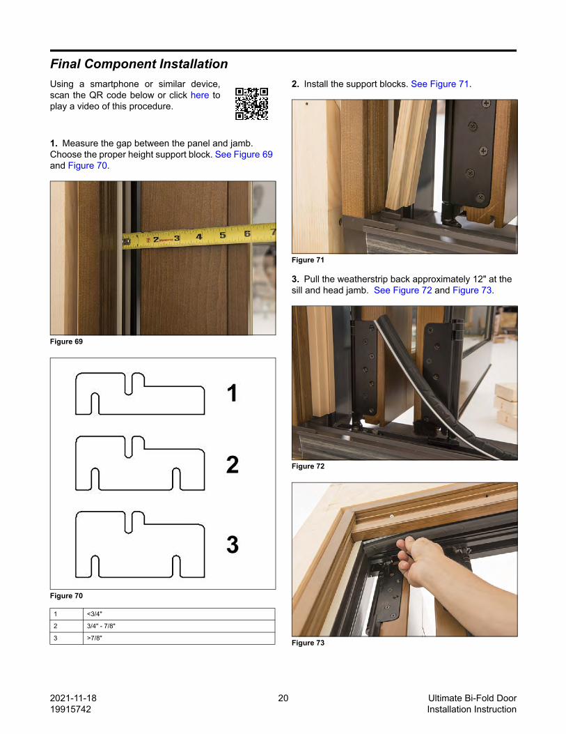
Frame AssemblyUsing a smartphone or similar device,scan the QR code or click here to play avideo of this procedure.
NOTE: If the door is over 23 1/2 feet, refer to Sill Splic-ing on page 6 prior to frame assembly.
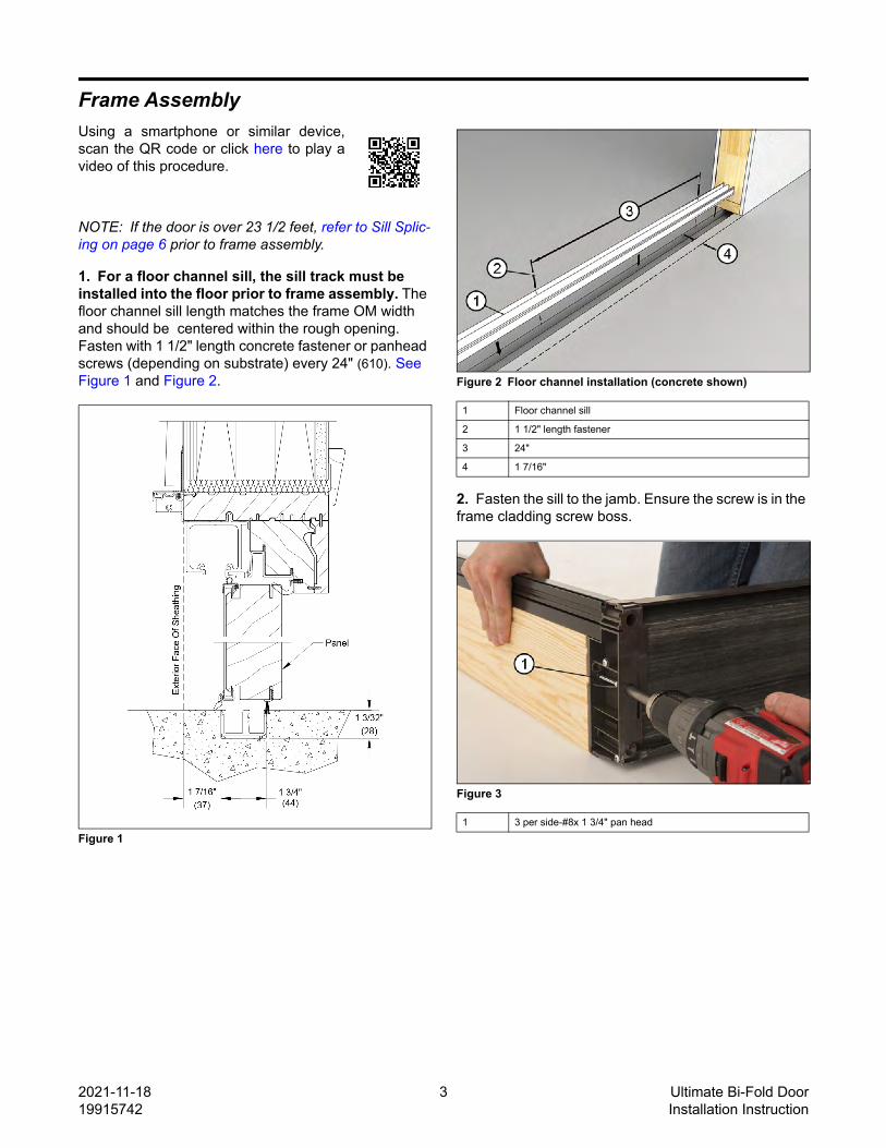
1. For a floor channel sill, the sill track must be installed into the floor prior to frame assembly. The floor channel sill length matches the frame OM width and should be centered within the rough opening. Fasten with 1 1/2" length concrete fastener or panhead screws (depending on substrate) every 24" (610). See Figure 1 and Figure 2.
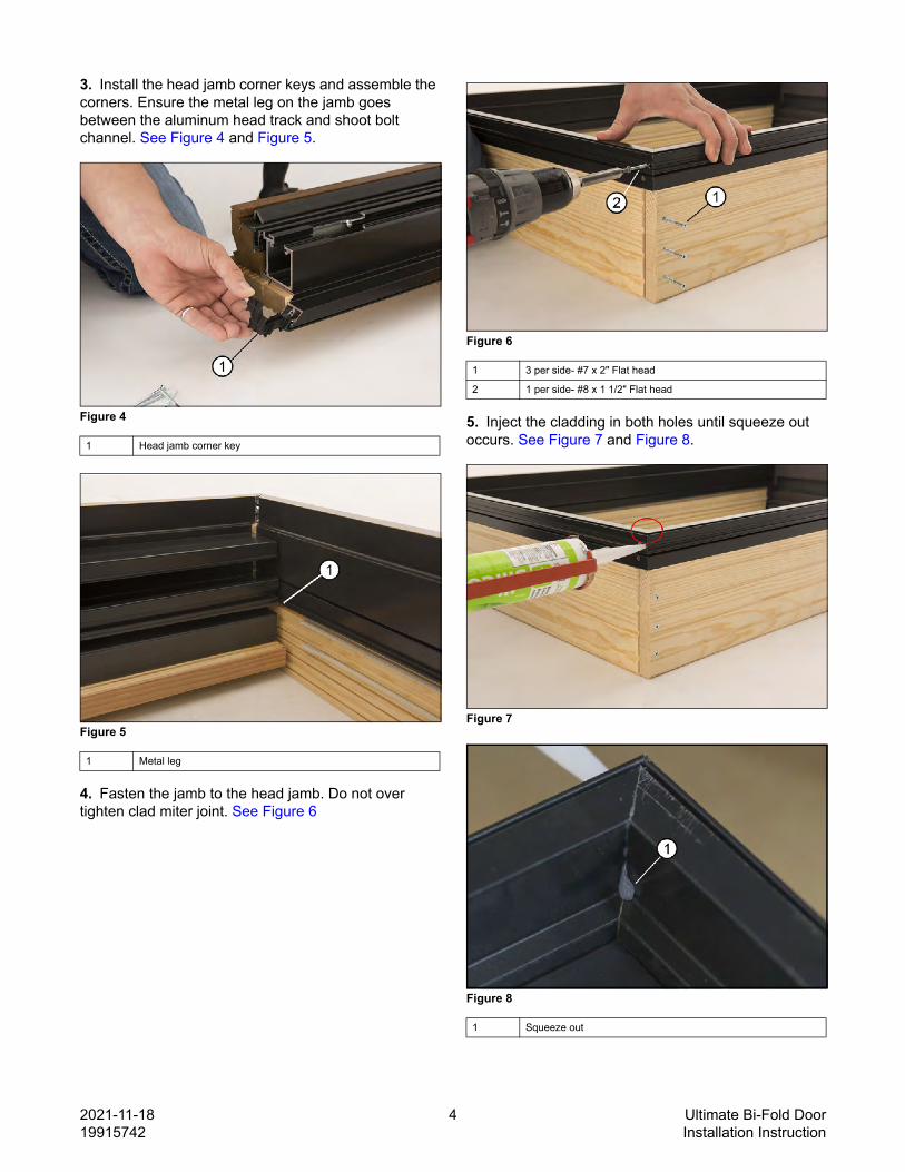
3. Install the head jamb corner keys and assemble the corners. Ensure the metal leg on the jamb goes between the aluminum head track and shoot bolt channel. See Figure 4 and Figure 5.
Figure 4
Figure 5
4. Fasten the jamb to the head jamb. Do not over tighten clad miter joint. See Figure 6
Figure 6
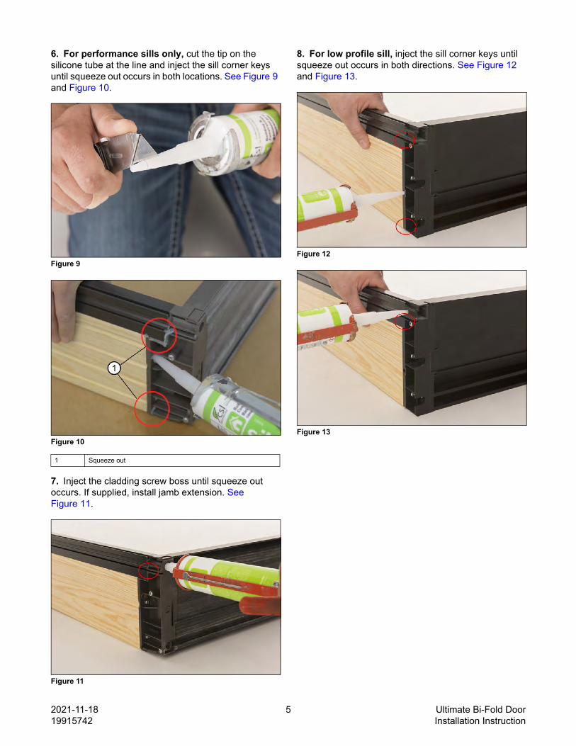
5. Inject the cladding in both holes until squeeze out occurs. See Figure 7 and Figure 8.
6. For performance sills only, cut the tip on the silicone tube at the line and inject the sill corner keys until squeeze out occurs in both locations. See Figure 9 and Figure 10.
Figure 9
Figure 10
7. Inject the cladding screw boss until squeeze out occurs. If supplied, install jamb extension. See Figure 11.
Figure 11
8. For low profile sill, inject the sill corner keys until squeeze out occurs in both directions. See Figure 12 and Figure 13.
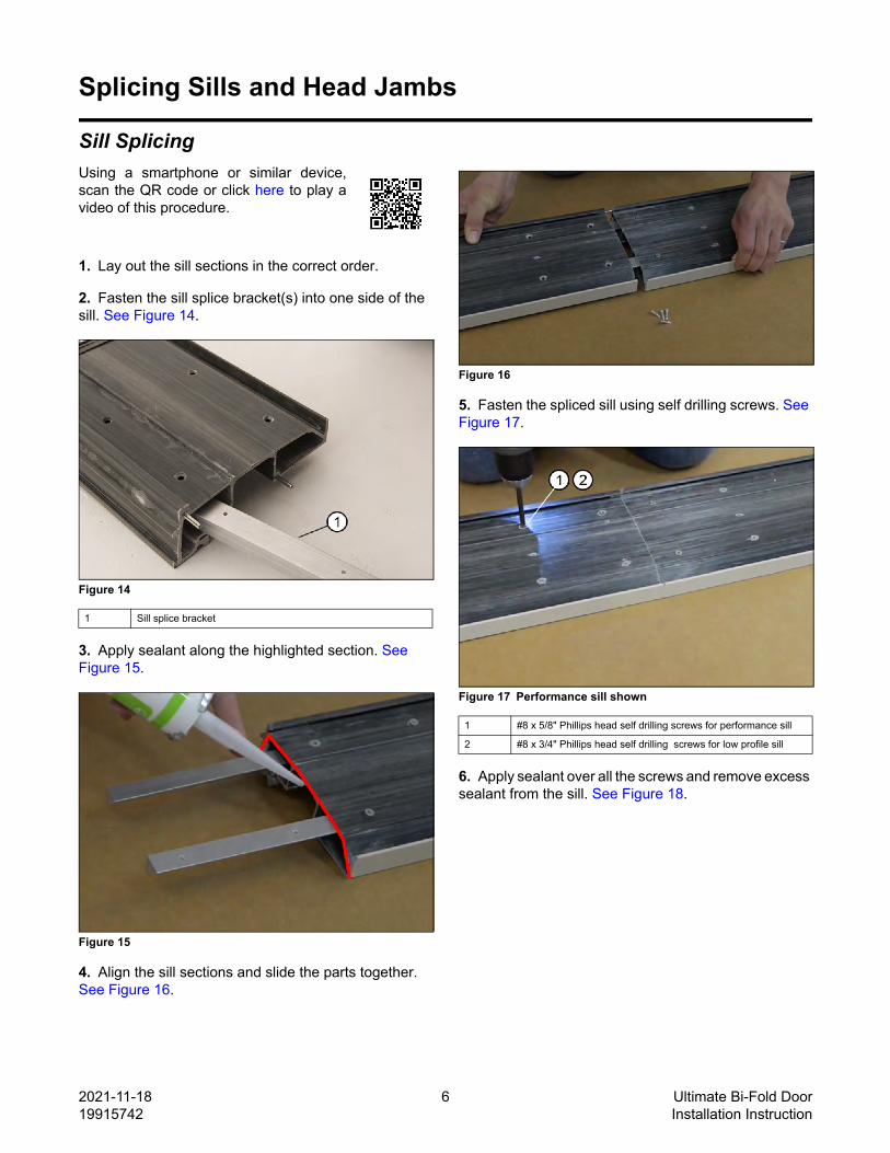
6. Fasten the support block to the head jamb. See Figure 23. Pre-drill the head jamb track installation holes with a 1/4" bit using the holes in the head track as a guide.
Figure 23
7. Install the shoot bolt channel. See Figure 24.
Figure 24
8. Flip the head jamb over. Fasten the frame cladding splicing key. See Figure 25.
Figure 25
9. Pre-drill the head jamb with a 1/8" bit using the hole in the frame cladding as a guide. Do not drill through the face of the frame cladding. See Figure 26.
Figure 26
10. Inject both holes until squeeze out occurs on opposite sides. See Figure 27.
11. Insert the weatherstrip 11/16" (17) from the end of the support block. See Figure 28.
Figure 28
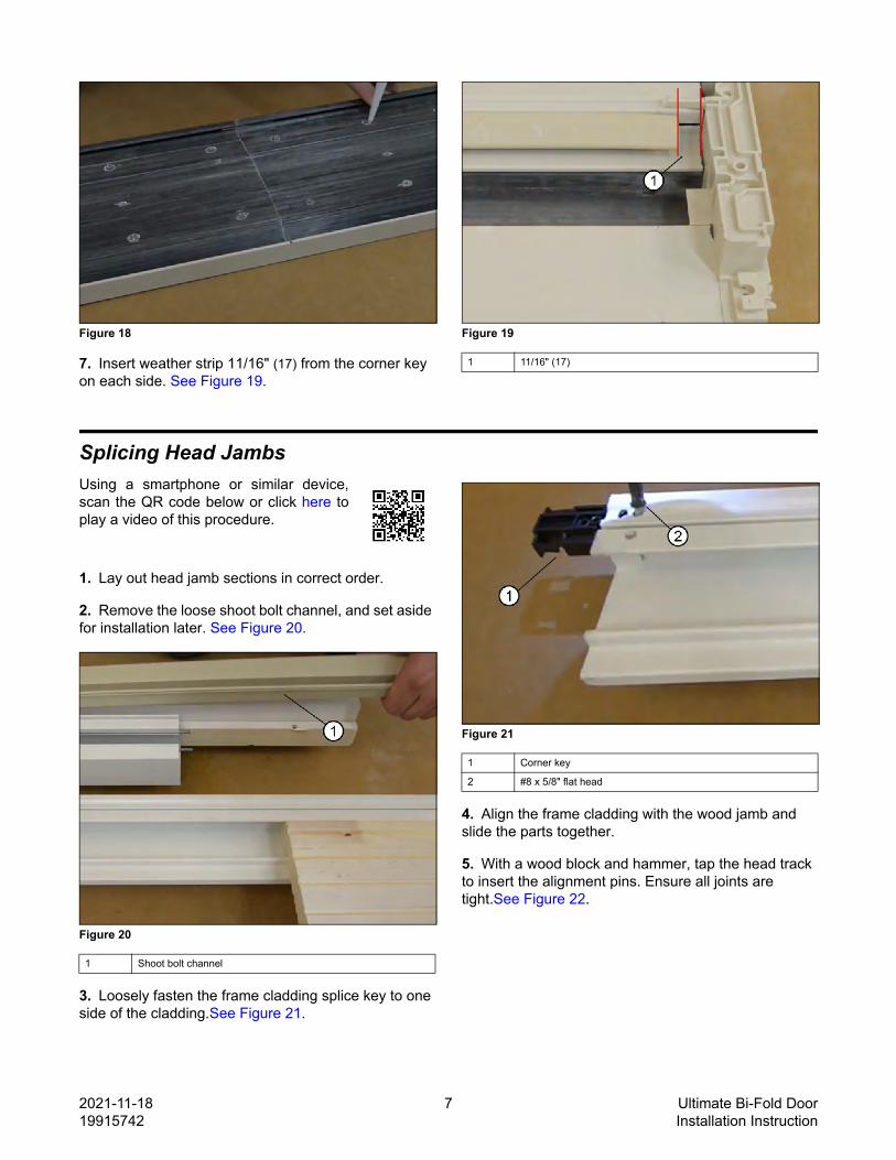
Frame InstallationUsing a smartphone or similar device,scan the QR code below or click here toplay a video of this procedure.
NOTE: Before installation, ensure the Rough Openinghas been prepped according to the site prep guide.
1. Frame Tolerance: the sill must be within +/- 1/16" (2) flat. The head jamb must be flat or within +1/16" of flat (not bowed down). When installed, the frame must be within +/- 3/16" (5) of square. See Figure 29.
Figure 29 Frame tolerance
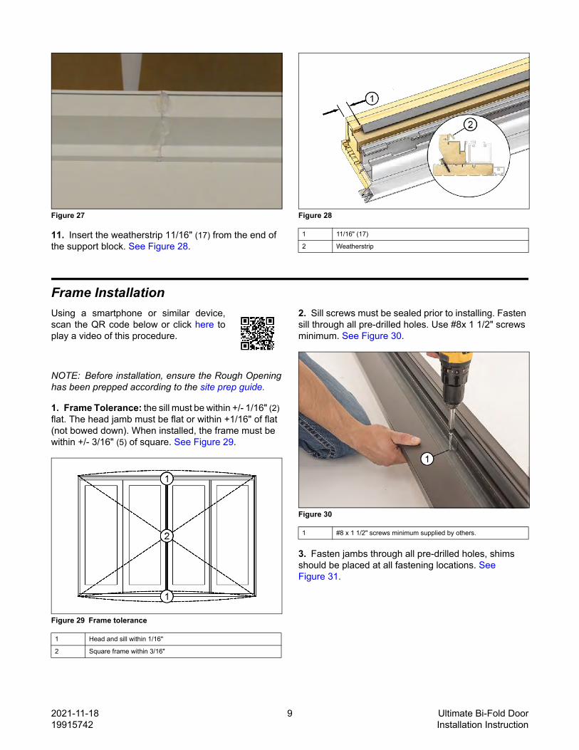
2. Sill screws must be sealed prior to installing. Fasten sill through all pre-drilled holes. Use #8x 1 1/2" screws minimum. See Figure 30.
Figure 30
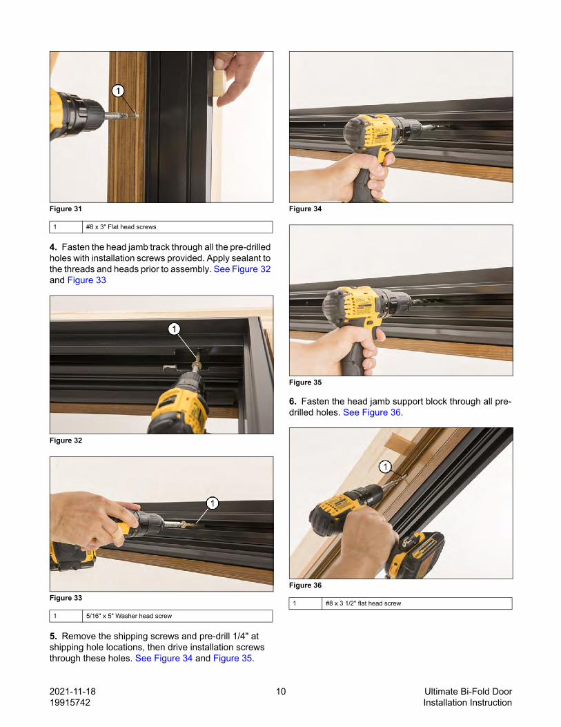
3. Fasten jambs through all pre-drilled holes, shims should be placed at all fastening locations. See Figure 31.
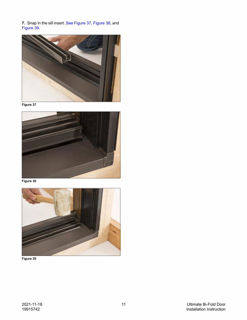
4. Fasten the head jamb track through all the pre-drilled holes with installation screws provided. Apply sealant to the threads and heads prior to assembly. See Figure 32 and Figure 33
Figure 32
Figure 33
5. Remove the shipping screws and pre-drill 1/4" at shipping hole locations, then drive installation screws through these holes. See Figure 34 and Figure 35.
Figure 34
Figure 35
6. Fasten the head jamb support block through all pre-drilled holes. See Figure 36.
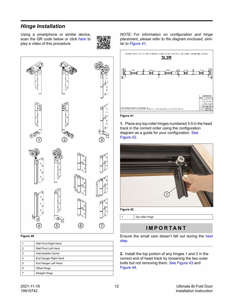
Hinge InstallationUsing a smartphone or similar device,scan the QR code below or click here toplay a video of this procedure.
Figure 40
NOTE: For information on configuration and hingeplacement, please refer to the diagram enclosed, simi-lar to Figure 41.
Figure 41
1. Place any top roller hinges numbered 3-5 in the head track in the correct order using the configuration diagram as a guide for your configuration. See Figure 42.
Figure 42
I M P O R TA N TEnsure the small cam doesn’t fall out during the nextstep.
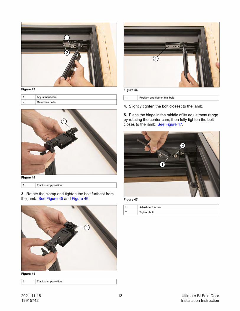
2. Install the top portion of any hinges 1 and 2 in the correct end of head track by loosening the two outer bolts but not removing them. See Figure 43 and Figure 44.
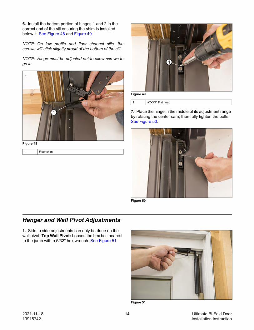
6. Install the bottom portion of hinges 1 and 2 in the correct end of the sill ensuring the shim is installed below it. See Figure 48 and Figure 49.
NOTE: On low profile and floor channel sills, thescrews will stick slightly proud of the bottom of the sill.
NOTE: Hinge must be adjusted out to allow screws togo in.
Figure 48
Figure 49
7. Place the hinge in the middle of its adjustment range by rotating the center cam, then fully tighten the bolts. See Figure 50.
Figure 50
Hanger and Wall Pivot Adjustments1. Side to side adjustments can only be done on the wall pivot. Top Wall Pivot: Loosen the hex bolt nearest to the jamb with a 5/32" hex wrench. See Figure 51.
2. Turn the center adjustment cam with a 3/16" hex wrench to adjust the panel side to side. Tighten the bolt that was loosened. See Figure 52.
Figure 52
3. Bottom Wall Pivot: Loosen both 5/32" hex bolts slightly. See Figure 53.
Figure 53
4. Turn the center adjustment cam with a 3/16" hex wrench to adjust side to side. Tighten the hex bolts that were loosened earlier. See Figure 54
Figure 54
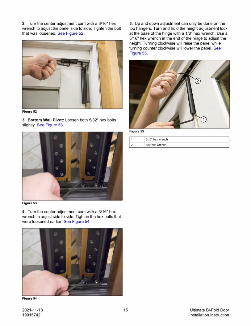
5. Up and down adjustment can only be done on the top hangers. Turn and hold the height adjustment lock at the base of the hinge with a 1/8" hex wrench. Use a 3/16" hex wrench in the end of the hinge to adjust the height. Turning clockwise will raise the panel while turning counter clockwise will lower the panel. See Figure 55.
Panel InstallationUsing a smartphone or similar device,scan the QR code below or click here toplay a video of this procedure.
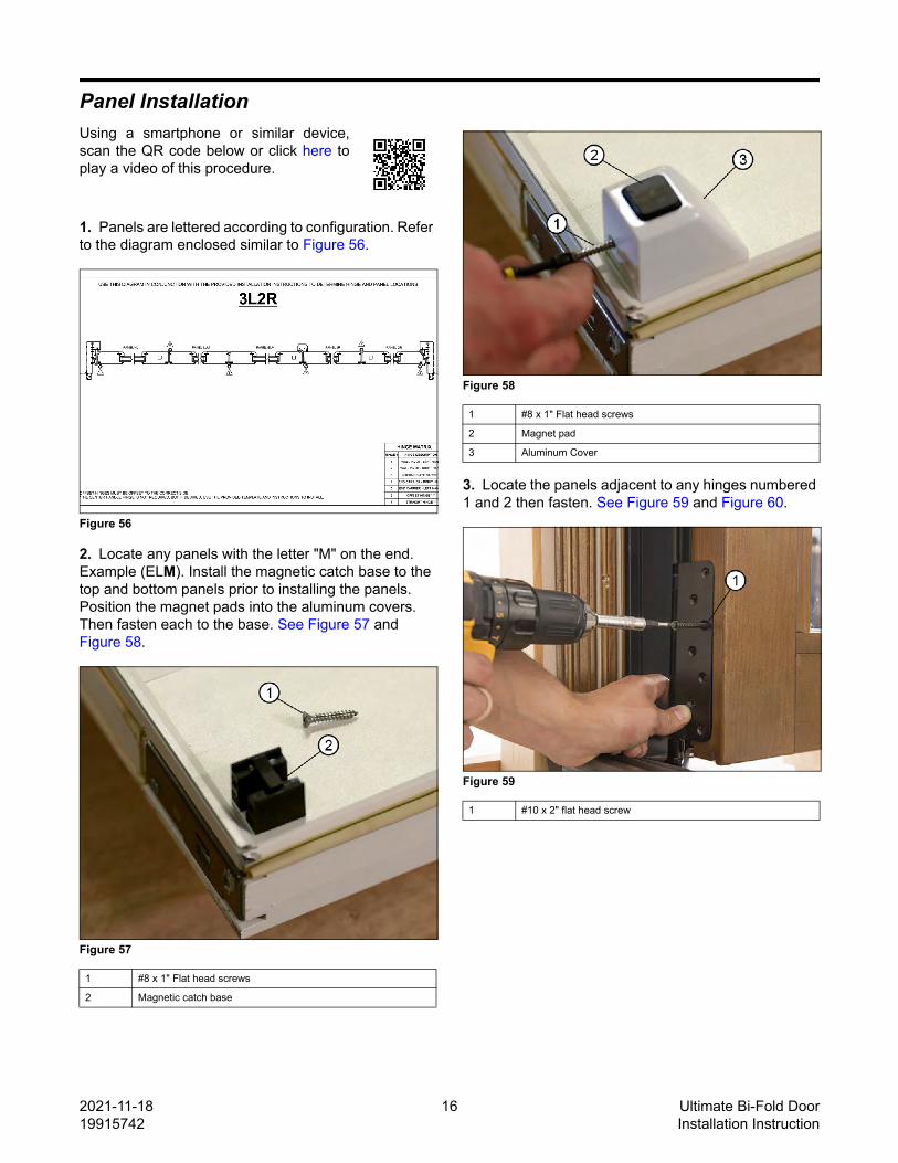
1. Panels are lettered according to configuration. Refer to the diagram enclosed similar to Figure 56.
Figure 56
2. Locate any panels with the letter "M" on the end. Example (ELM). Install the magnetic catch base to the top and bottom panels prior to installing the panels. Position the magnet pads into the aluminum covers. Then fasten each to the base. See Figure 57 and Figure 58.
Figure 57
Figure 58
3. Locate the panels adjacent to any hinges numbered 1 and 2 then fasten. See Figure 59 and Figure 60.
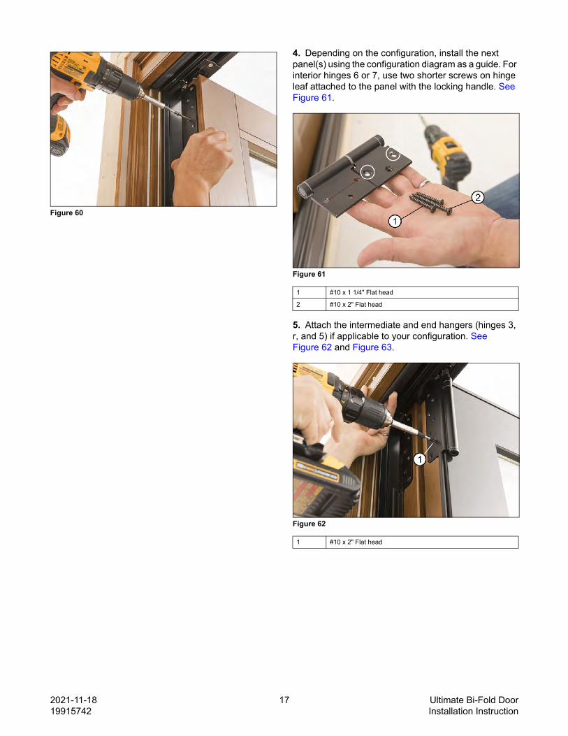
4. Depending on the configuration, install the next panel(s) using the configuration diagram as a guide. For interior hinges 6 or 7, use two shorter screws on hinge leaf attached to the panel with the locking handle. See Figure 61.
Figure 61
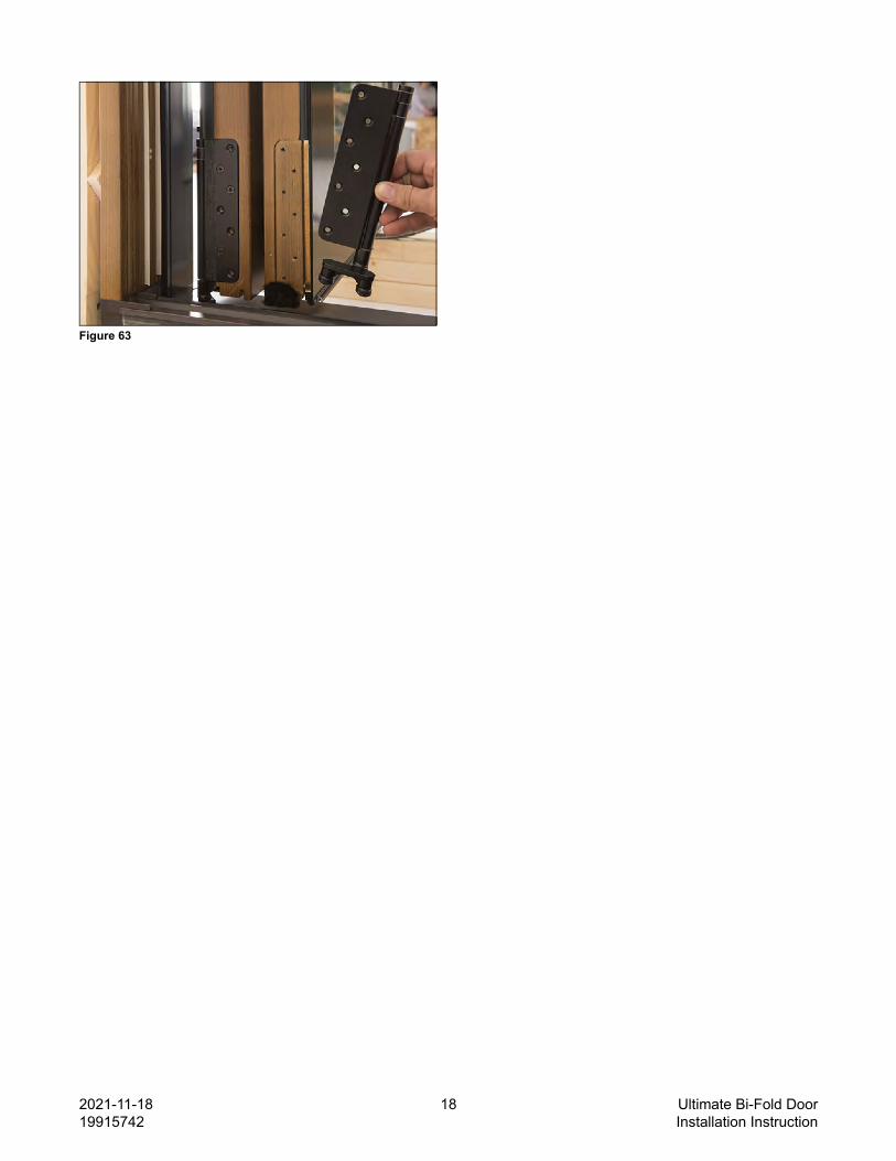
5. Attach the intermediate and end hangers (hinges 3, r, and 5) if applicable to your configuration. See Figure 62 and Figure 63.
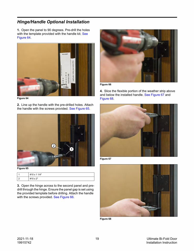
Hinge/Handle Optional Installation1. Open the panel to 90 degrees. Pre-drill the holes with the template provided with the handle kit. See Figure 64.
Figure 64
2. Line up the handle with the pre-drilled holes. Attach the handle with the screws provided. See Figure 65.
Figure 65
3. Open the hinge across to the second panel and pre-drill through the hinge. Ensure the panel gap is set using the provided template before drilling. Attach the handle with the screws provided. See Figure 66.
Figure 66
4. Slice the flexible portion of the weather strip above and below the installed handle. See Figure 67 and Figure 68.
8. Install the panel alignment bolt(s) into pre-drilled holes on jambs where wall pivot hinge sets are located.See Figure 79.
Figure 79
9. If needed, install the strike plate using the pre-drilled holes. Ensure the support block does not interfere and there are shims behind the jamb. See Figure 80.
Figure 80
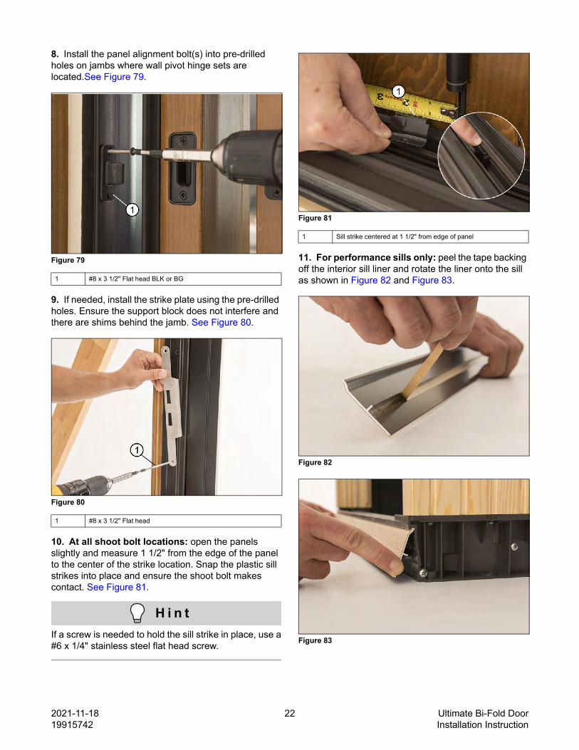
10. At all shoot bolt locations: open the panels slightly and measure 1 1/2" from the edge of the panel to the center of the strike location. Snap the plastic sill strikes into place and ensure the shoot bolt makes contact. See Figure 81.
H i n tIf a screw is needed to hold the sill strike in place, use a#6 x 1/4" stainless steel flat head screw.
Figure 81
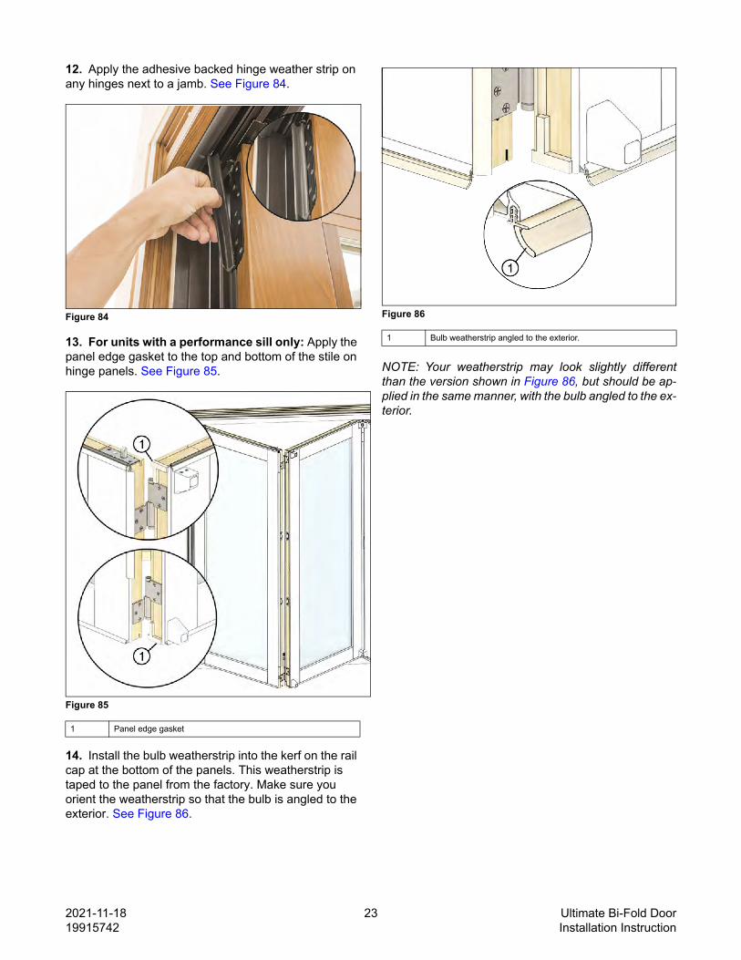
11. For performance sills only: peel the tape backing off the interior sill liner and rotate the liner onto the sill as shown in Figure 82 and Figure 83.
Figure 82
Figure 83
1 #8 x 3 1/2" Flat head BLK or BG
1 #8 x 3 1/2" Flat head
1 Sill strike centered at 1 1/2" from edge of panel
12. Apply the adhesive backed hinge weather strip on any hinges next to a jamb. See Figure 84.
Figure 84
13. For units with a performance sill only: Apply the panel edge gasket to the top and bottom of the stile on hinge panels. See Figure 85.
Figure 85
14. Install the bulb weatherstrip into the kerf on the rail cap at the bottom of the panels. This weatherstrip is taped to the panel from the factory. Make sure you orient the weatherstrip so that the bulb is angled to the exterior. See Figure 86.
Figure 86
NOTE: Your weatherstrip may look slightly differentthan the version shown in Figure 86, but should be ap-plied in the same manner, with the bulb angled to the ex-terior.
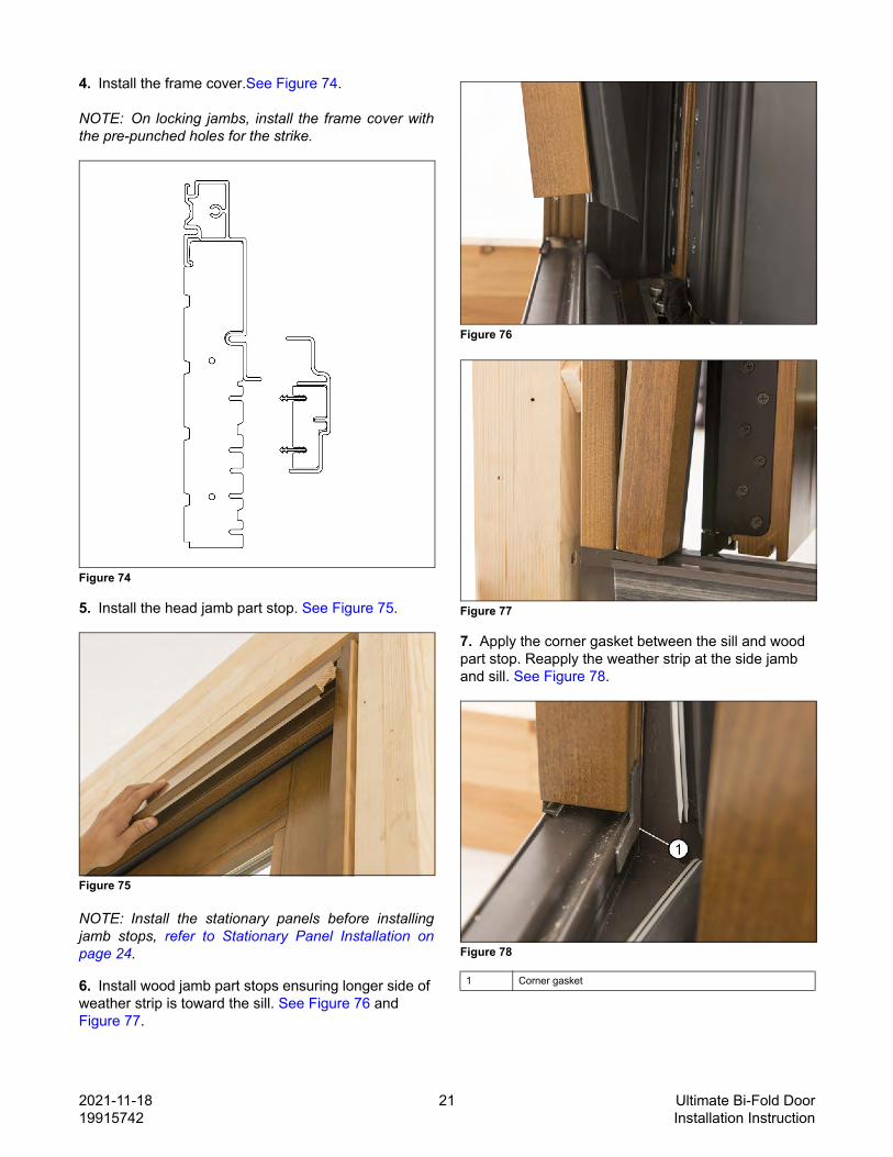
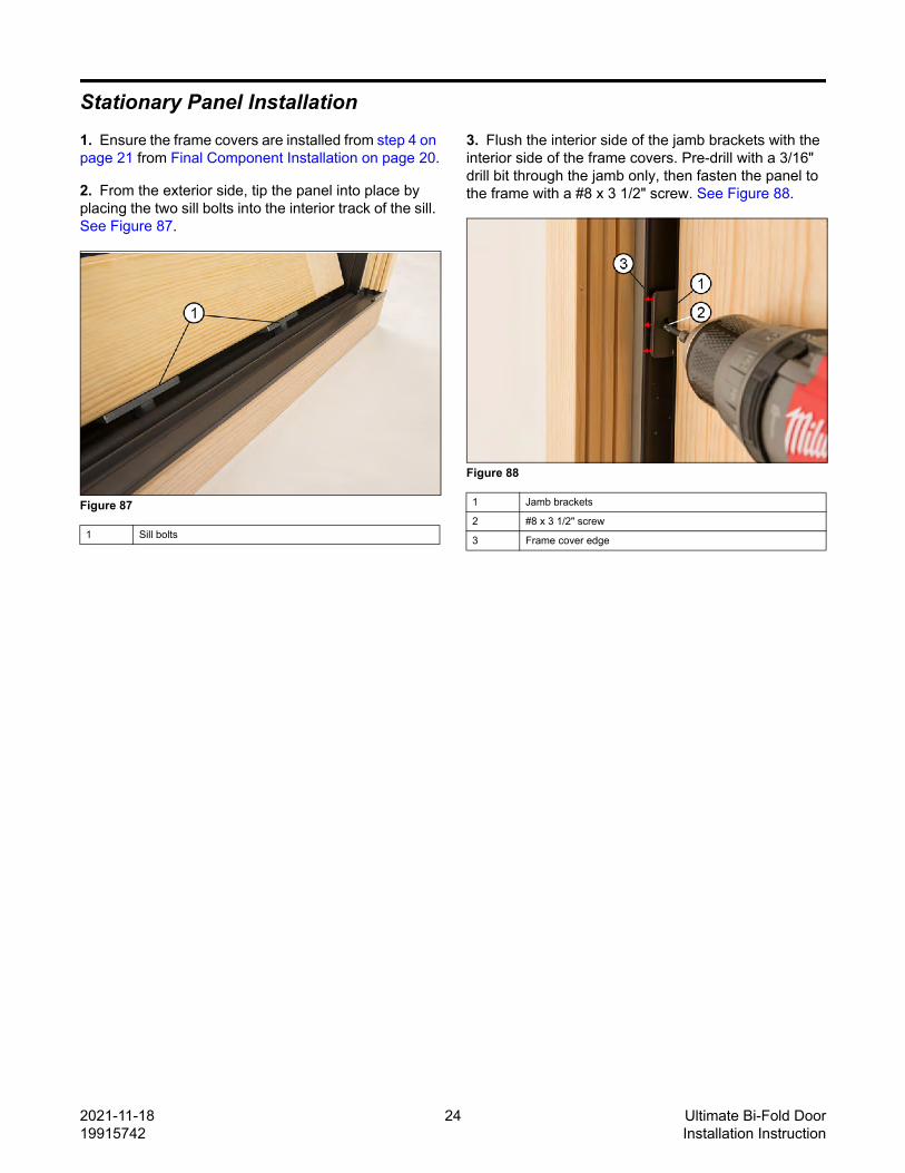
Stationary Panel Installation1. Ensure the frame covers are installed from step 4 on page 21 from Final Component Installation on page 20.
2. From the exterior side, tip the panel into place by placing the two sill bolts into the interior track of the sill. See Figure 87.
Figure 87
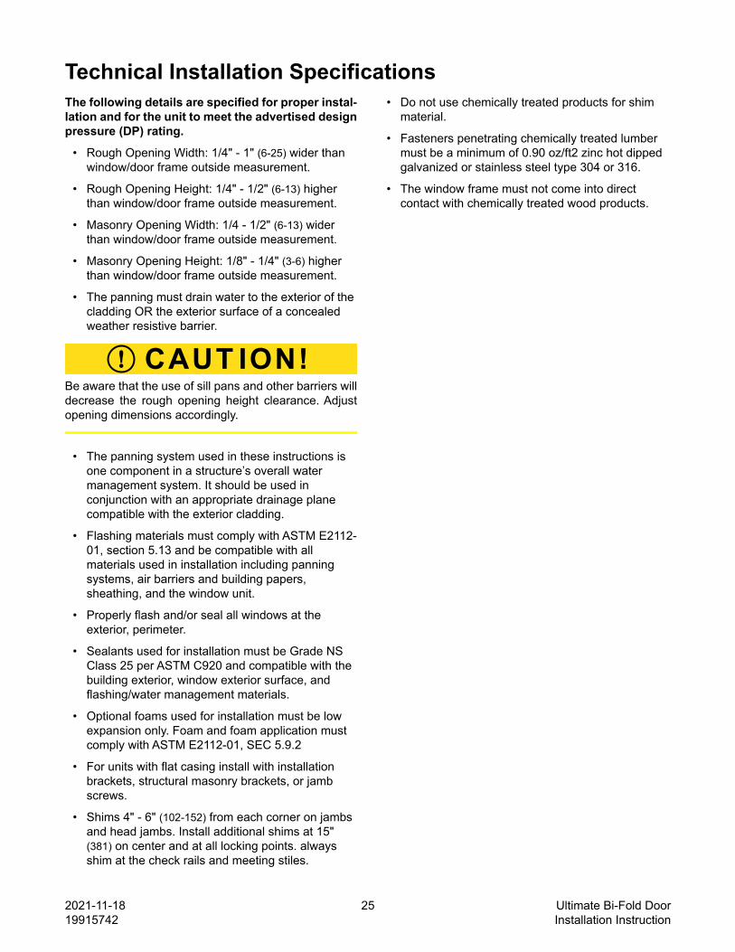
3. Flush the interior side of the jamb brackets with the interior side of the frame covers. Pre-drill with a 3/16" drill bit through the jamb only, then fasten the panel to the frame with a #8 x 3 1/2" screw. See Figure 88.
Technical Installation SpecificationsThe following details are specified for proper instal-lation and for the unit to meet the advertised designpressure (DP) rating.
• The panning must drain water to the exterior of the cladding OR the exterior surface of a concealed weather resistive barrier.
CAUT ION!Be aware that the use of sill pans and other barriers willdecrease the rough opening height clearance. Adjustopening dimensions accordingly.
• The panning system used in these instructions is one component in a structure’s overall water management system. It should be used in conjunction with an appropriate drainage plane compatible with the exterior cladding.
• Flashing materials must comply with ASTM E2112-01, section 5.13 and be compatible with all materials used in installation including panning systems, air barriers and building papers, sheathing, and the window unit.
• Properly flash and/or seal all windows at the exterior, perimeter.
• Sealants used for installation must be Grade NS Class 25 per ASTM C920 and compatible with the building exterior, window exterior surface, and flashing/water management materials.
• Optional foams used for installation must be low expansion only. Foam and foam application must comply with ASTM E2112-01, SEC 5.9.2
• For units with flat casing install with installation brackets, structural masonry brackets, or jamb screws.
• Shims 4" - 6" (102-152) from each corner on jambs and head jambs. Install additional shims at 15" (381) on center and at all locking points. always shim at the check rails and meeting stiles.
• Do not use chemically treated products for shim material.
• Fasteners penetrating chemically treated lumber must be a minimum of 0.90 oz/ft2 zinc hot dipped galvanized or stainless steel type 304 or 316.
• The window frame must not come into direct contact with chemically treated wood products.