30
Ultra ™ Installation Instructions Movable and Stationary Models Form 5908-5
Ultra™
Installation InstructionsMovable and Stationary Models
Form 5908-5

Blank Page
Page I
Safety InformationFor your safety, read this manual thoroughly before installation of the equipment.
Installation is intended to be performed by properly trained technicians. The safety messages presentedhere are reminders to the installer to exercise extreme caution during installation and training on thealigner.
There are many variations in procedures, techniques, tools, and parts for installation due to varied shopconfigurations. Because of the vast versatility of installation the manufacturer cannot possibly anticipateor provide advice or safety messages to cover every situation. It is the technician’s responsibility to beknowledgeable of the equipment to be installed. It is essential to use proper service methods andperform installation in an appropriate and acceptable manner that does not endanger your safety, thesafety of others in the work area, the end user, the equipment or vehicle being serviced.
It is assumed that, prior to installation of the aligner, the operator has a thorough understanding ofimaging alignment systems in general. In addition, it is assumed he has a thorough knowledge of theoperation and safety features of the alignment rack or lift, and has the proper hand and power toolsnecessary to perform the installation in a safe manor.
These safety precautions should always be followed, including:
1. Read all instructions.2. Care must be taken as burns can occur from touching hot parts.3. Do not operate power tools or equipment with a damaged power cord or if the equipment has been
dropped or damaged until it has been examined by a qualified serviceman.4. Do not let cord hang over edge of table, bench or counter or come in contact with hot manifolds or
moving fan blades.5. If an extension cord is necessary, a cord with a current rating equal to or more than that of the
equipment should be used. Cords rated for less than the equipment may overheat. Care shouldbe taken to arrange the cord so that it will not be tripped over or pulled.
6. Always unplug equipment from electrical outlet when not in use. Never use the cord to pull theplug from the outlet. Grasp plug and pull to disconnect.
7. Let equipment cool completely before putting away. Loop cord loosely around equipment whenstoring.
8. To reduce the risk of fire, do not operate equipment in the vicinity of open containers of flammableliquids, such as gasoline.
9. Adequate ventilation should be provided when working on operating internal combustion engines.10. Keep hair, loose clothing, fingers, and all parts of body away from moving parts.11. To reduce the risk of electrical shock, do not use on wet surfaces or expose to rain.12. Use only as described in this manual. Use only manufacturer’s recommended attachments.13. ALWAYS WEAR SAFETY GLASSES. Everyday eyeglasses only have impact resistant lenses,
they are NOT safety glasses.14. Know and understand the proper operating procedures for all power tools used.
IMPORTANT!! SAVE THESE INSTRUCTIONSDO NOT DISCARD!!

Page II
Page III
Table of Contents
SAFETY INFORMATION ...................................................................................................... I
INTRODUCTION .................................................................................................................. 1INSTALLATION PROCEDURES .......................................................................................... 2TOOLS AND EQUIPMENT REQUIRED FOR INSTALLATION ............................................ 2ASSEMBLY AND SETUP OF THE CONSOLE .................................................................... 3QUALIFY THE SITE FOR INSTALLATION .......................................................................... 5INSTALLATION BASELINE LAYOUT .................................................................................. 6INSTALLATION DIMENSIONS WORKSHEET .................................................................... 7SUPPORT BASE ASSEMBLY .......................................................................................... 10ATTACHING THE CAMERA BEAM - SINGLE COLUMN RIGID SUPPORT ......................11DUAL COLUMN SUPPORT ASSEMBLY ........................................................................... 13MOVABLE BEAM INSTALLATION ..................................................................................... 15CABLE CONNECTION ...................................................................................................... 18SYSTEM START-UP AND CAMERA AIM ......................................................................... 19SYSTEM TRAINING .......................................................................................................... 21ULTRA MOVABLE OPERATION INSTRUCTIONS ............................................................ 21
Page 1
Ultra™ Installation Instructions
INTRODUCTION
An Ultra™ aligner is installed much the same as conventional imaging aligners, howeverthere are unique considerations which must be addressed. Follow these instructionscarefully for a successful installation.
An Ultra™ aligner normally does not require RCP calibration at installation. The camerabeam is pre-assembled and is factory calibrated and can be placed into service shortlyafter installation and setup. Camera subassemblies do not have to be replaced as a pair.It is possible to replace camera assemblies individually. A field “RCP” calibration proce-dure must be performed whenever a camera is replaced, moved or disturbed.
Three types of camera beam mounts are available at this writing, a single rigid, a dual rigidcolumn support, and a movable beam support. This document covers installation of rigidsupports, as well as a movable beam supports. Some steps covering moveable installa-tion may not be applicable to rigid installations and vice vera.
These instructions cover the main topics of Ultra™ installation:Preparing for installationQualifying the site for installationConsole assembly and setupPlacement and assembly of the base and support columnCamera Beam mounting proceduresCable ConnectionInitial operation of Ultra™ software
Before attempting installation, read these instructions thoroughly and understand the tasksinvolved. Review all requirements of installation to avoid oversights resulting in lost rev-enue, and lost customer confidence. Be aware of the environment conducive to the opti-mum performance of imaging alignment. Procure the necessary tools to do a quality joband last and most important, perform the installation safely by observing all precautionsassociated with the task at hand.
Page 2
INSTALLATION PROCEDURES
1. TOOLS AND EQUIPMENT REQUIRED FOR INSTALLATION
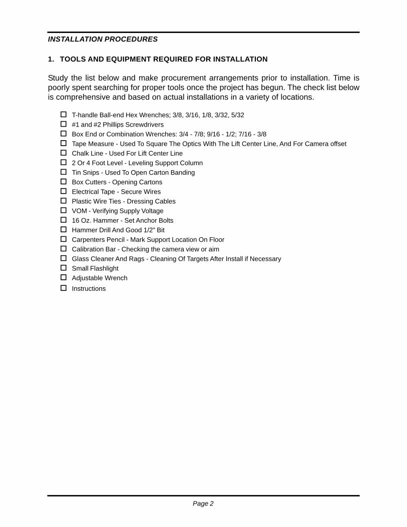
Study the list below and make procurement arrangements prior to installation. Time ispoorly spent searching for proper tools once the project has begun. The check list belowis comprehensive and based on actual installations in a variety of locations.
T-handle Ball-end Hex Wrenches; 3/8, 3/16, 1/8, 3/32, 5/32#1 and #2 Phillips ScrewdriversBox End or Combination Wrenches: 3/4 - 7/8; 9/16 - 1/2; 7/16 - 3/8Tape Measure - Used To Square The Optics With The Lift Center Line, And For Camera offsetChalk Line - Used For Lift Center Line2 Or 4 Foot Level - Leveling Support ColumnTin Snips - Used To Open Carton BandingBox Cutters - Opening CartonsElectrical Tape - Secure WiresPlastic Wire Ties - Dressing CablesVOM - Verifying Supply Voltage16 Oz. Hammer - Set Anchor BoltsHammer Drill And Good 1/2” BitCarpenters Pencil - Mark Support Location On FloorCalibration Bar - Checking the camera view or aimGlass Cleaner And Rags - Cleaning Of Targets After Install if NecessarySmall FlashlightAdjustable WrenchInstructions
Page 3
Ultra™ Installation Instructions
ASSEMBLY AND SETUP OF THE CONSOLE
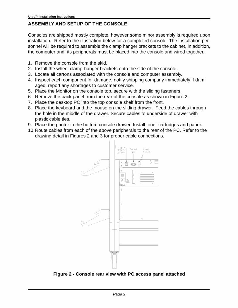
Consoles are shipped mostly complete, however some minor assembly is required uponinstallation. Refer to the illustration below for a completed console. The installation per-sonnel will be required to assemble the clamp hanger brackets to the cabinet, In addition,the computer and its peripherals must be placed into the console and wired together.
1. Remove the console from the skid.2. Install the wheel clamp hanger brackets onto the side of the console.3. Locate all cartons associated with the console and computer assembly.4. Inspect each component for damage, notify shipping company immediately if dam
aged, report any shortages to customer service.5. Place the Monitor on the console top, secure with the sliding fasteners.6. Remove the back panel from the rear of the console as shown in Figure 2.7. Place the desktop PC into the top console shelf from the front.8. Place the keyboard and the mouse on the sliding drawer. Feed the cables through
the hole in the middle of the drawer. Secure cables to underside of drawer withplastic cable ties.
9. Place the printer in the bottom console drawer. Install toner cartridges and paper.10.Route cables from each of the above peripherals to the rear of the PC. Refer to the
drawing detail in Figures 2 and 3 for proper cable connections.
Figure 2 - Console rear view with PC access panel attached
Page 4
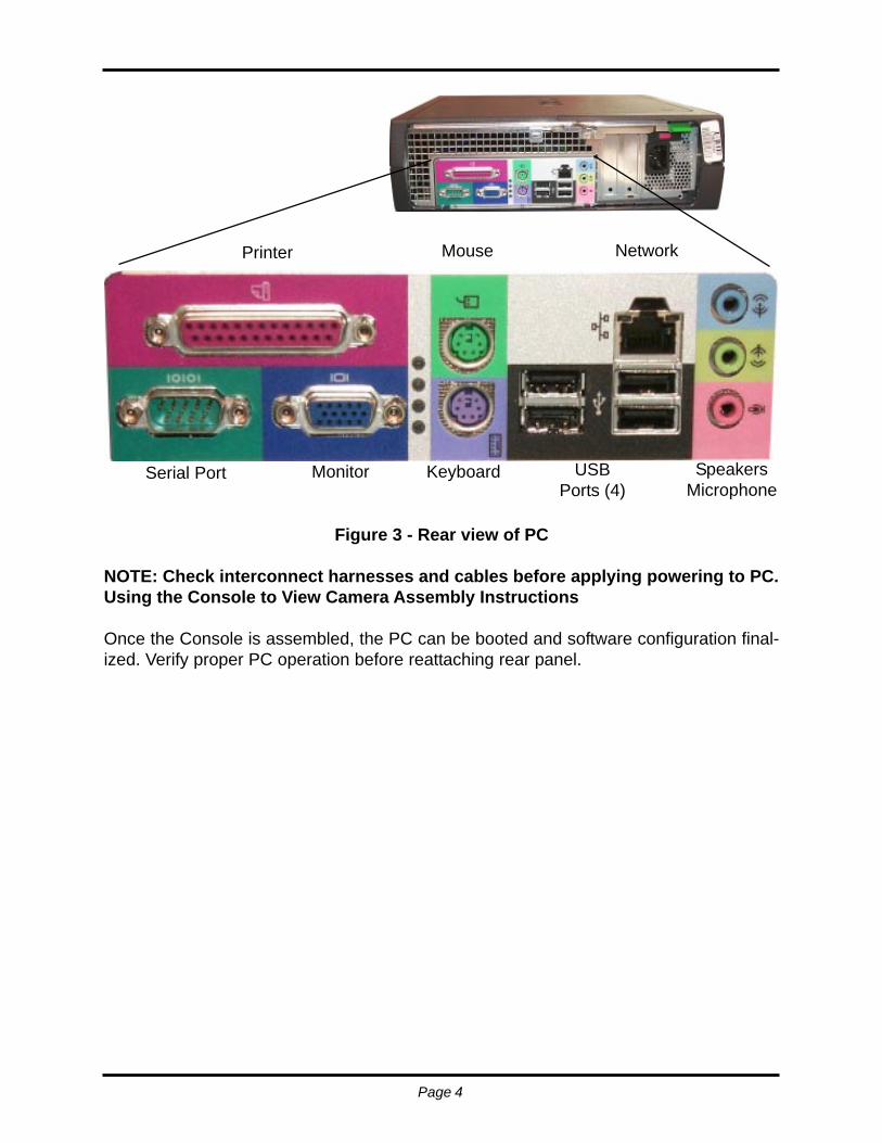
Figure 3 - Rear view of PC
NOTE: Check interconnect harnesses and cables before applying powering to PC.Using the Console to View Camera Assembly Instructions
Once the Console is assembled, the PC can be booted and software configuration final-ized. Verify proper PC operation before reattaching rear panel.
Printer
Serial Port Monitor Keyboard USBPorts (4)
SpeakersMicrophone
Mouse Network
Page 5
Ultra™ Installation Instructions
QUALIFY THE SITE FOR INSTALLATIONThe Pre-Installation checklist was created primarily with sales personnel in mind, howeverit can be used as tool to verify bay conformance to requirements. Below are some keyissues to consider for a successful installation. See Figures 4 and 5 on pages 8 and 9 fora typical bay layout.
Power Source115 volts AC, 15 amp noise free dedicated service, assure a good ground
Rack integrity:Is the rack/lift safe, are the lock mechanisms secure?Check for runway coplanar at all heightsIs rack relatively level? - for ease of rollbackTurntable condition - free from binding, do they exhibit good rotational stabilityRollback requirements - is a kit required - acquire if necessaryIs the field of view conducive with imaging alignment (no obstructions)
Floor integrity:Will the floor adequately support the rack, has a core test been performed?Is the concrete properly cured?, new flooring should be cured at least 28 daysAre there any pipes, or wiring under the floor that could be drilled into?Will the floor flex, crumble, are there expansion joints?
Environmental concernsInspect the area for heaters, reflections, adjacent machinery, fans, RFI etc.
Space requirementsCan the Camera face be positioned from the Turntable a distance of 80” to 114”(measured from the front mounting hole in the base plate to center of TT)
NOTE: Camera face is on the same vertical plane as the front base plate hole
Adjacent Power NoiseLook for motor noise/hash, shared processors, RFI
ErgonomicsCan the operator move about freely to work safely and view the CRT?Will the movable camera beam feature be utilized in the installation?

Page 6
INSTALLATION BASELINE LAYOUT
These instructions assume a lift or rack is being used as the alignment surface. If the flooris to be used, identify the spot where the turntables will rest, and base measurementsfrom that spot. Reference Installation Dimensions Worksheet 1 for the following steps.
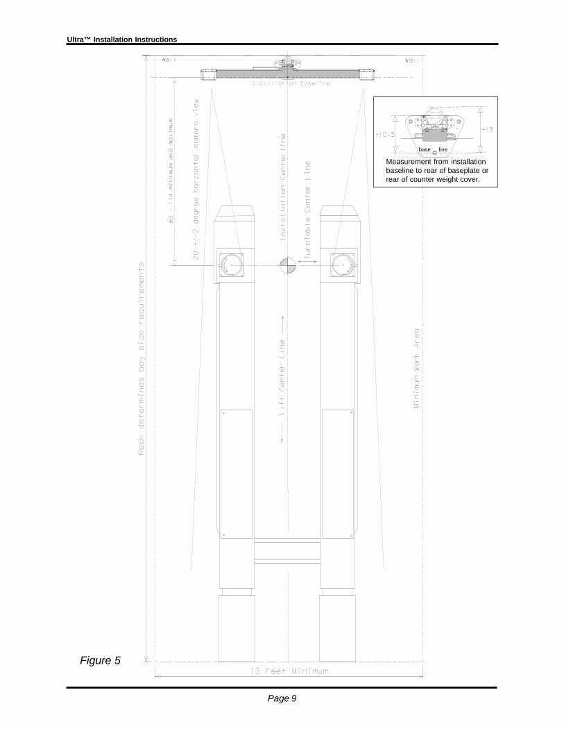
1. Determine the Lift Centerline. Measure between runways front and rear and markmidpoints on both. A mark can be made forward of the lift by placing one end of a stringat a spot on one side of the lift, placing a marker on the other end of a string, andscribing an arc forward of the lift across the centerline. Repeat scribing an arc from thesame spot on the other side of the lift. The intersection of the two arcs is the liftcenterline. Use a chalk line to snap a centerline between the marks, and project out atleast 114 inches in front of the rack, or to the shop wall if closer. See Figure 5.
2. Determine the Turntable Centerline by raising the lift to the predetermined alignmentheight. Use a plumb-bob from the center of the turntable and mark a spot on the floornext to each turntable. Snap a chalk line through the marks to establish the centerline.Use the plumb bob on the outside of the turntables to mark a center spot on the flooron the outside of each runway. See Figure 5.
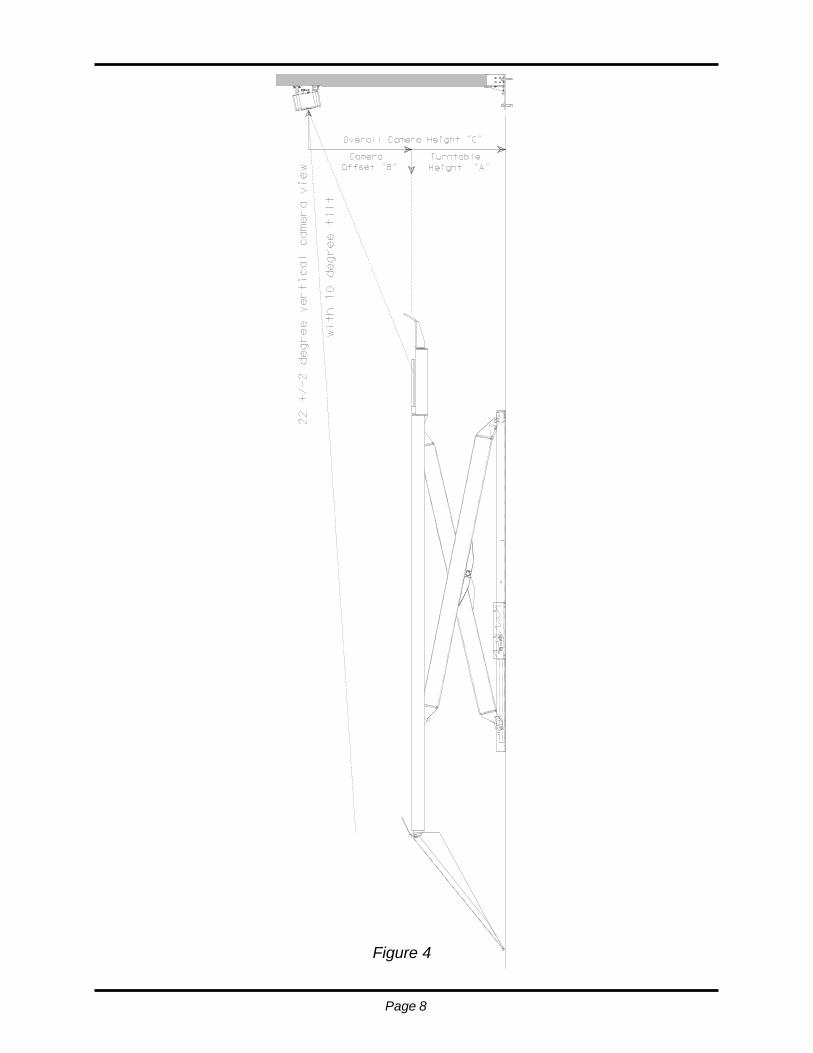
3. Determine the Turntable Height (the normal operating height of the rack). On a mul-tilevel lift (i.e. parallelogram) put an average size car on the lift and raise it until thealignment technician feels comfortable performing wheel turns, rolling the vehicle backand forth, and making toe/camber adjustments from underneath. On other lifts/racks(such as a hoist rack) it is necessary to use the leveling leg height. Typical turntableheight is from 30” to 36”. See Figure 4, page 8.
Measure the distance from the floor to the top of the lift turntables, recordthis value in the worksheet as TURNTABLE HEIGHT, measurement “A”
If the user will be operating the Ultra™ without the moveable beam option you maywant to mark this height position so it is easy to raise the lift to this chosen height later– this is the height the operator must use when performing alignments. One way is tohang a chain from the lift so it hangs just off of the ground when the rack is at alignmentheight – this should be visible from the lift operation controls.
4. Determine the Installation Baseline. The Ultra™ camera supports must be installeda minimum of 80 inches (2032 mm), and no greater than 114 inches (2896 mm) fromthe center of the turntables to the front bolt hole of the support base. Measure thedistance desired within above parameters from the turntable centerline forward at twolocations and mark these points. Snap a chalk line on the floor through these twopoints. This is the installation baseline used to locate the front base anchor bolt. (SeeFigure 5). Record this distance in the INSTALLATION DIMENSIONS WORKSHEETshown on page 7.
Page 7
Ultra™ Installation Instructions
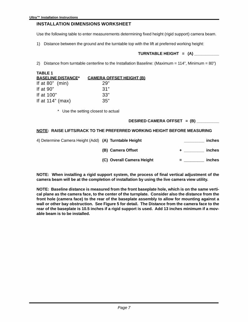
INSTALLATION DIMENSIONS WORKSHEET
Use the following table to enter measurements determining fixed height (rigid support) camera beam.
1) Distance between the ground and the turntable top with the lift at preferred working height:
TURNTABLE HEIGHT = (A) ___________
2) Distance from turntable centerline to the Installation Baseline: (Maximum = 114”, Minimum = 80”)
TABLE 1BASELINE DISTANCE* CAMERA OFFSET HEIGHT (B)If at 80” (min) 29”If at 90” 31”If at 100” 33”If at 114” (max) 35”
* Use the setting closest to actual
DESIRED CAMERA OFFSET = (B) __________
NOTE: RAISE LIFTS/RACK TO THE PREFERRED WORKING HEIGHT BEFORE MEASURING
4) Determine Camera Height (Add) (A) Turntable Height _________ inches
(B) Camera Offset + _________ inches
(C) Overall Camera Height = _________ inches
NOTE: When installing a rigid support system, the process of final vertical adjustment of thecamera beam will be at the completion of installation by using the live camera view utility.
NOTE: Baseline distance is measured from the front baseplate hole, which is on the same verti-cal plane as the camera face, to the center of the turnplate. Consider also the distance from thefront hole (camera face) to the rear of the baseplate assembly to allow for mounting against awall or other bay obstruction. See Figure 5 for detail. The Distance from the camera face to therear of the baseplate is 10.5 inches if a rigid support is used. Add 13 inches minimum if a mov-able beam is to be installed.
Page 8
Figure 4
Page 9
Ultra™ Installation Instructions
Figure 5
Measurement from installationbaseline to rear of baseplate orrear of counter weight cover.
base line

Page 10
SUPPORT BASE ASSEMBLY
The support base assembly is shipped pre-assembled, however in the event componentassembly is required follow these instructions for proper procedures.
1. Loosely assemble eight (8) T-nuts onto the support bracket. Note the location of nutextrusions, they should face away from the support. Refer to Figure 6 for orientation.Do not tighten screws at this time.
2. Mount Support Bracket/T-nut assembly onto base plate as shown in Figure 6 andsecure using seven (7) 5/16-18 cap screws. Snug but do not tighten, hardware will betightened when support column is placed onto the base.
3. Position column/base assembly onto floor and square up with the installation baselineand lift center line using measurements made earlier. Refer to Figure 5 on Page 9 forlayout detail. Using a marker, mark the front anchor hole location.
Figure 6
4. Using a rotary hammer drill equipped with a good 1/2 x 12 inch bit, bore the front holecarefully. It is generally a good idea to drill all the way through the slab so that if theanchor must be removed later, it can be driven through the concrete and into theground below. Clear debris before proceeding.
HINT: Bore only the front anchor hole, tap in an anchor bolt, then bore remaining holes
NOTE: Do not pound anchors into holes. Excessive pounding will deform the anchorbolts and make future service difficult.
Page 11
Ultra™ Installation Instructions
HINT: Pour a small amount of water into the hole as it is being bored to significantlyreduce concrete dust. Use a shop vacuum to clean area before proceeding.
! ! DO NOT BOLT DOWN BASE PLATE AT THIS TIME ! !
5. Slide vertical support column downward onto the support/base assembly. Tighten sup-port to column screws firmly followed by tightening the support to base screws.
ATTACHING THE CAMERA BEAM - SINGLE COLUMN RIGID SUPPORT
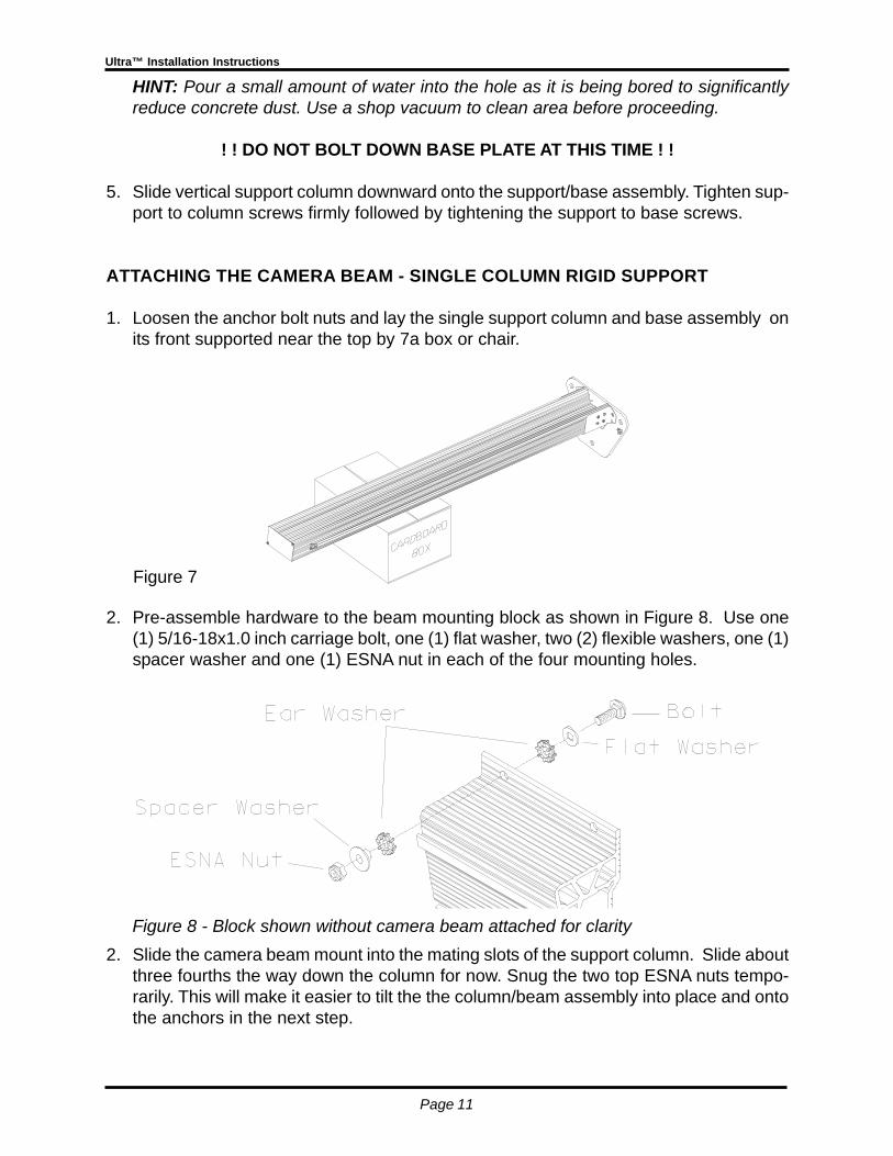
1. Loosen the anchor bolt nuts and lay the single support column and base assembly onits front supported near the top by 7a box or chair.
2. Pre-assemble hardware to the beam mounting block as shown in Figure 8. Use one(1) 5/16-18x1.0 inch carriage bolt, one (1) flat washer, two (2) flexible washers, one (1)spacer washer and one (1) ESNA nut in each of the four mounting holes.
2. Slide the camera beam mount into the mating slots of the support column. Slide aboutthree fourths the way down the column for now. Snug the two top ESNA nuts tempo-rarily. This will make it easier to tilt the the column/beam assembly into place and ontothe anchors in the next step.
Figure 8 - Block shown without camera beam attached for clarity
Figure 7
Page 12
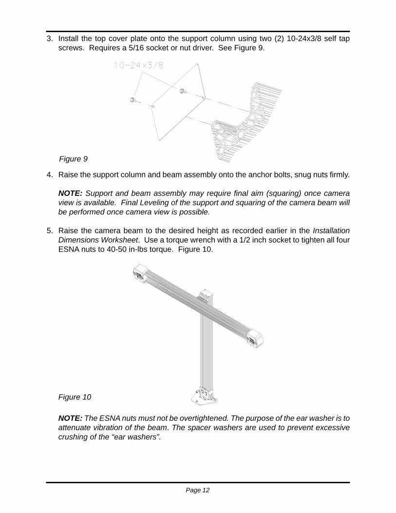
3. Install the top cover plate onto the support column using two (2) 10-24x3/8 self tapscrews. Requires a 5/16 socket or nut driver. See Figure 9.
4. Raise the support column and beam assembly onto the anchor bolts, snug nuts firmly.
NOTE: Support and beam assembly may require final aim (squaring) once cameraview is available. Final Leveling of the support and squaring of the camera beam willbe performed once camera view is possible.
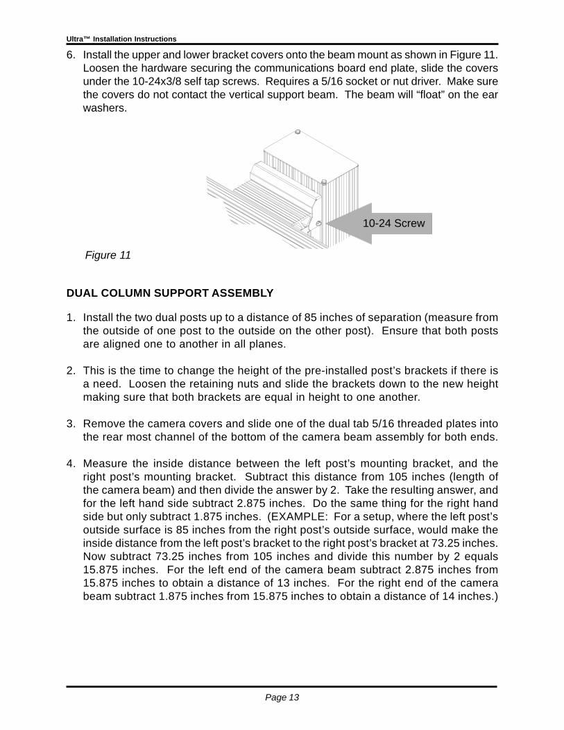
5. Raise the camera beam to the desired height as recorded earlier in the InstallationDimensions Worksheet. Use a torque wrench with a 1/2 inch socket to tighten all fourESNA nuts to 40-50 in-lbs torque. Figure 10.
NOTE: The ESNA nuts must not be overtightened. The purpose of the ear washer is toattenuate vibration of the beam. The spacer washers are used to prevent excessivecrushing of the “ear washers”.
Figure 10
Figure 9
Page 13
Ultra™ Installation Instructions
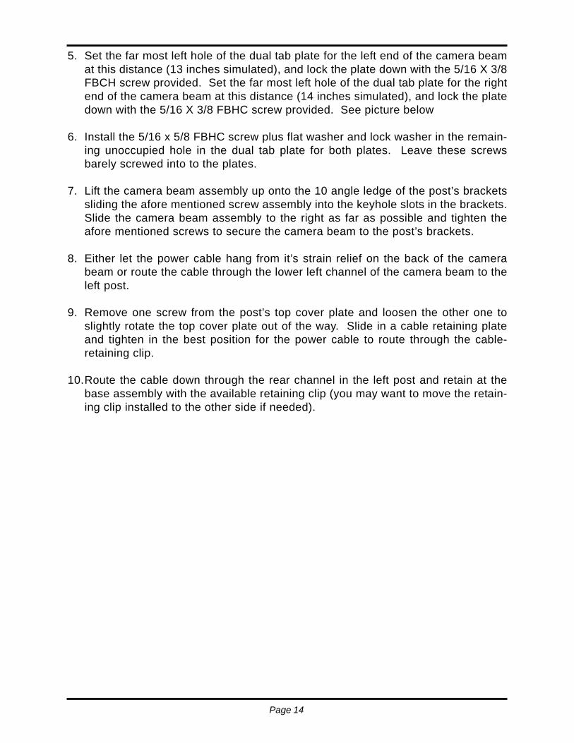
6. Install the upper and lower bracket covers onto the beam mount as shown in Figure 11.Loosen the hardware securing the communications board end plate, slide the coversunder the 10-24x3/8 self tap screws. Requires a 5/16 socket or nut driver. Make surethe covers do not contact the vertical support beam. The beam will “float” on the earwashers.
DUAL COLUMN SUPPORT ASSEMBLY
1. Install the two dual posts up to a distance of 85 inches of separation (measure fromthe outside of one post to the outside on the other post). Ensure that both postsare aligned one to another in all planes.
2. This is the time to change the height of the pre-installed post’s brackets if there isa need. Loosen the retaining nuts and slide the brackets down to the new heightmaking sure that both brackets are equal in height to one another.
3. Remove the camera covers and slide one of the dual tab 5/16 threaded plates intothe rear most channel of the bottom of the camera beam assembly for both ends.
4. Measure the inside distance between the left post’s mounting bracket, and theright post’s mounting bracket. Subtract this distance from 105 inches (length ofthe camera beam) and then divide the answer by 2. Take the resulting answer, andfor the left hand side subtract 2.875 inches. Do the same thing for the right handside but only subtract 1.875 inches. (EXAMPLE: For a setup, where the left post’soutside surface is 85 inches from the right post’s outside surface, would make theinside distance from the left post’s bracket to the right post’s bracket at 73.25 inches.Now subtract 73.25 inches from 105 inches and divide this number by 2 equals15.875 inches. For the left end of the camera beam subtract 2.875 inches from15.875 inches to obtain a distance of 13 inches. For the right end of the camerabeam subtract 1.875 inches from 15.875 inches to obtain a distance of 14 inches.)
10-24 Screw
Figure 11
Page 14
5. Set the far most left hole of the dual tab plate for the left end of the camera beamat this distance (13 inches simulated), and lock the plate down with the 5/16 X 3/8FBCH screw provided. Set the far most left hole of the dual tab plate for the rightend of the camera beam at this distance (14 inches simulated), and lock the platedown with the 5/16 X 3/8 FBHC screw provided. See picture below
6. Install the 5/16 x 5/8 FBHC screw plus flat washer and lock washer in the remain-ing unoccupied hole in the dual tab plate for both plates. Leave these screwsbarely screwed into to the plates.
7. Lift the camera beam assembly up onto the 10 angle ledge of the post’s bracketssliding the afore mentioned screw assembly into the keyhole slots in the brackets.Slide the camera beam assembly to the right as far as possible and tighten theafore mentioned screws to secure the camera beam to the post’s brackets.
8. Either let the power cable hang from it’s strain relief on the back of the camerabeam or route the cable through the lower left channel of the camera beam to theleft post.
9. Remove one screw from the post’s top cover plate and loosen the other one toslightly rotate the top cover plate out of the way. Slide in a cable retaining plateand tighten in the best position for the power cable to route through the cable-retaining clip.
10.Route the cable down through the rear channel in the left post and retain at thebase assembly with the available retaining clip (you may want to move the retain-ing clip installed to the other side if needed).
Page 15
Ultra™ Installation Instructions
MOVABLE BEAM INSTALLATION
1. Determine installation baseline and lift centerline as discussed earlier.
2. Place baseplate on floor in the desired position. Mark floor accordingly.
3. Drill holes and tap-in anchors. Do not mount the base plate at this time.
4 Place the lift near the intended installation location such that the bottom will be nearits final anchor point.
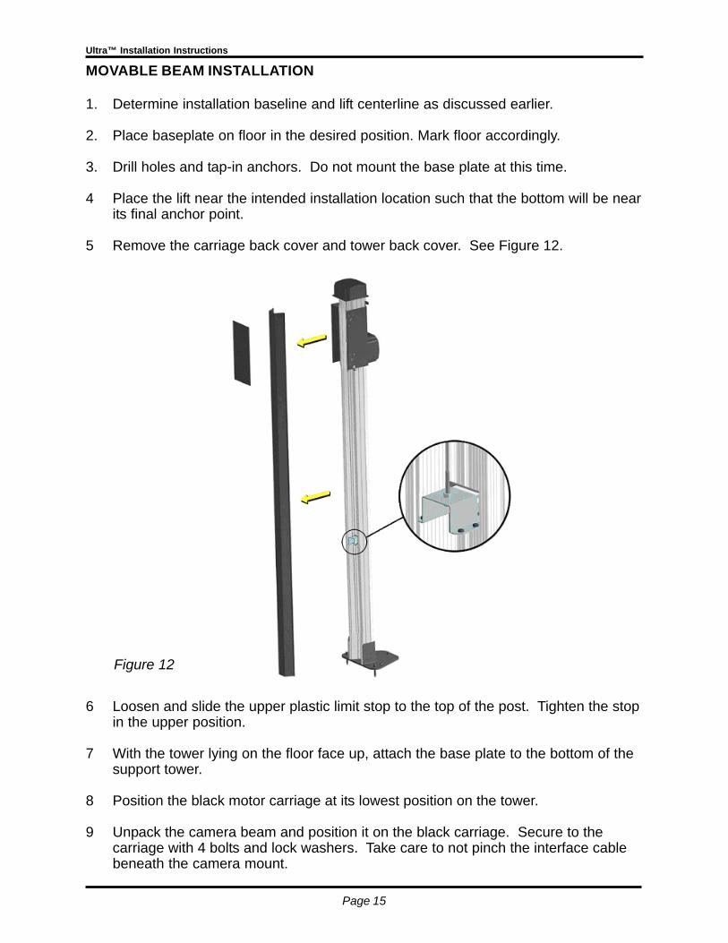
5 Remove the carriage back cover and tower back cover. See Figure 12.
6 Loosen and slide the upper plastic limit stop to the top of the post. Tighten the stopin the upper position.
7 With the tower lying on the floor face up, attach the base plate to the bottom of thesupport tower.
8 Position the black motor carriage at its lowest position on the tower.
9 Unpack the camera beam and position it on the black carriage. Secure to thecarriage with 4 bolts and lock washers. Take care to not pinch the interface cablebeneath the camera mount.
Figure 12
Page 16
10 Connect the motor interface cable to the hub board beneath the center of the cam-era beam mount. Verify the connector locks in place.
11 Lifting from the top of the tower, raise the assembly to its upright position.
12 Slide the assembly into its final position in front of the vehicle lift. Secure anchorbolts. Anchor bolts may be loosened for final aim and support leveling later.
13 Raise the camera beam by lifting on the camera beam at the center. Do not lift bythe motor cover.
14 Insert the provided rubber T-bolt stop as you get the beam to chest height to hold itin position. Continue to press the camera beam upward, stopping as close to thetower top as possible. Secure the beam in this raised position with the rubber T-bolt.
15 Remove the 100-lb counter weight from the carton. Also remove the woodencounter weight pallet from the carton for use in weight assembly placement.
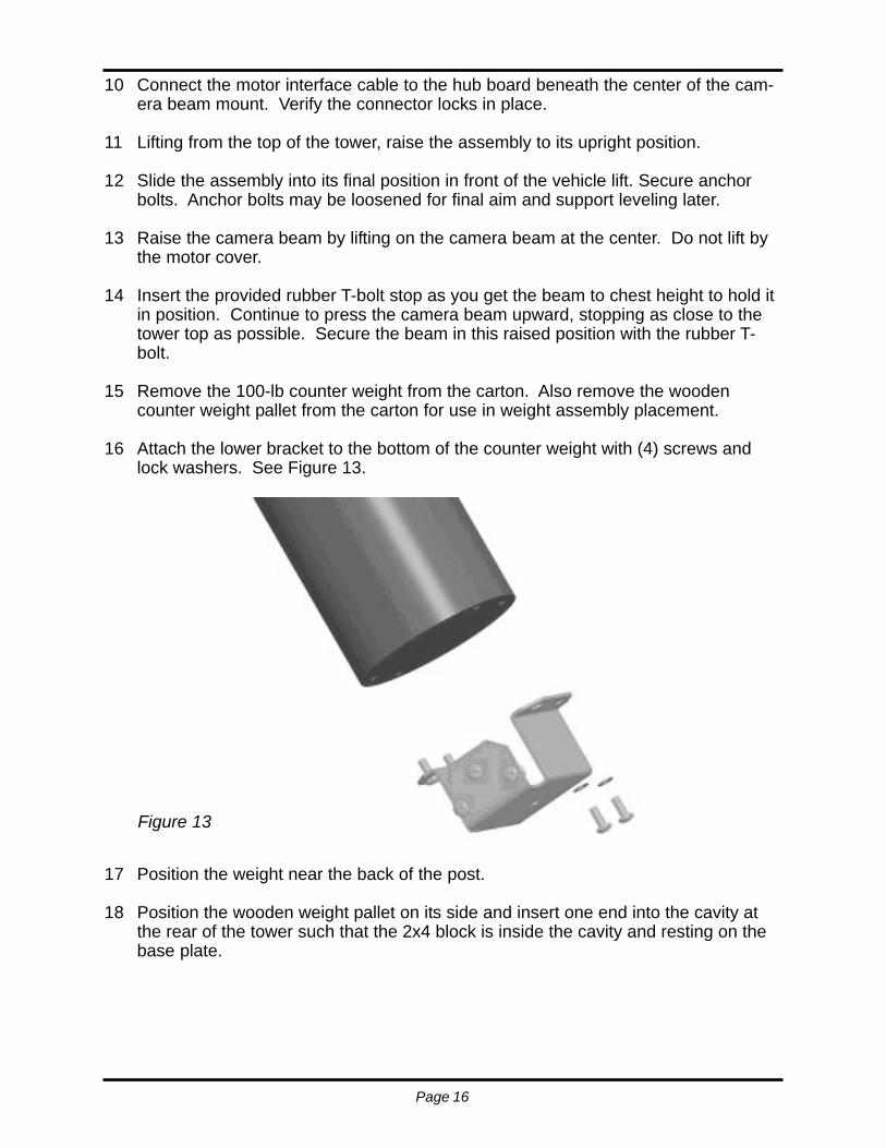
16 Attach the lower bracket to the bottom of the counter weight with (4) screws andlock washers. See Figure 13.
17 Position the weight near the back of the post.
18 Position the wooden weight pallet on its side and insert one end into the cavity atthe rear of the tower such that the 2x4 block is inside the cavity and resting on thebase plate.
Figure 13
Page 17
Ultra™ Installation Instructions
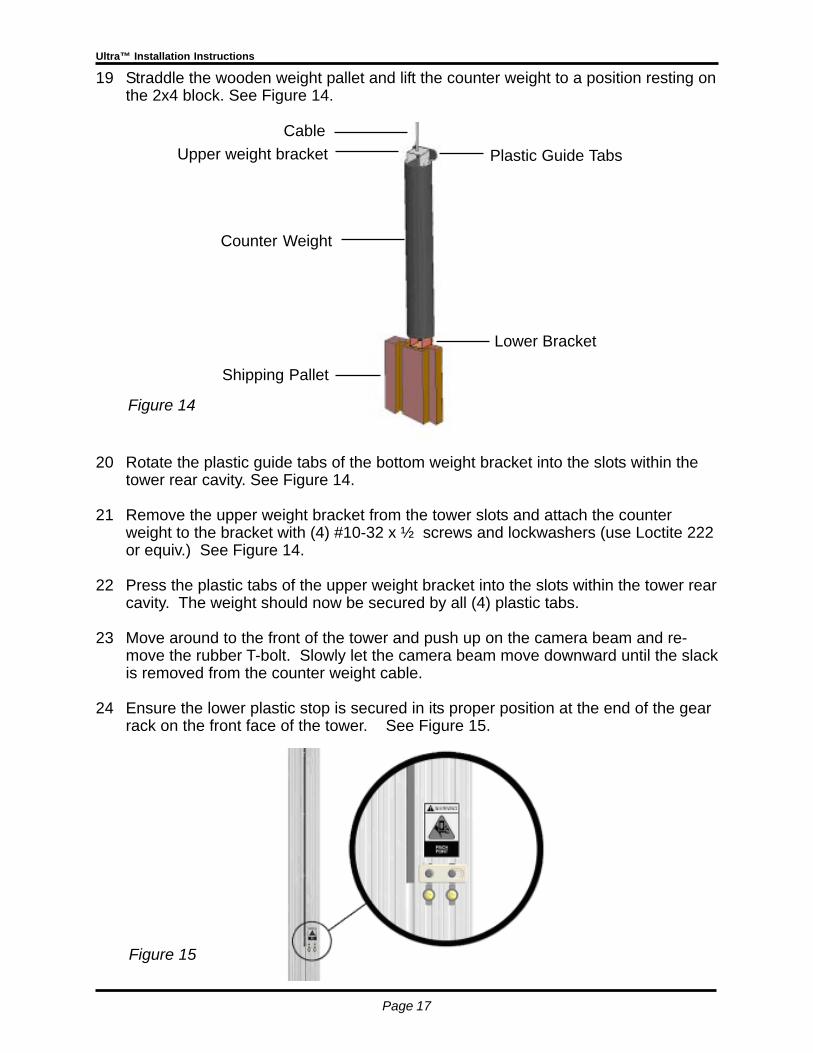
19 Straddle the wooden weight pallet and lift the counter weight to a position resting onthe 2x4 block. See Figure 14.
20 Rotate the plastic guide tabs of the bottom weight bracket into the slots within thetower rear cavity. See Figure 14.
21 Remove the upper weight bracket from the tower slots and attach the counterweight to the bracket with (4) #10-32 x ½ screws and lockwashers (use Loctite 222or equiv.) See Figure 14.
22 Press the plastic tabs of the upper weight bracket into the slots within the tower rearcavity. The weight should now be secured by all (4) plastic tabs.
23 Move around to the front of the tower and push up on the camera beam and re-move the rubber T-bolt. Slowly let the camera beam move downward until the slackis removed from the counter weight cable.
24 Ensure the lower plastic stop is secured in its proper position at the end of the gearrack on the front face of the tower. See Figure 15.
Figure 14
Figure 15
Shipping Pallet
Counter Weight
Cable
Lower Bracket
Plastic Guide TabsUpper weight bracket
Page 18
25 Move the camera beam to its lowest position to install the post plastic back cover.
25 Attach the carriage cover with (4) screws.
CABLE CONNECTION
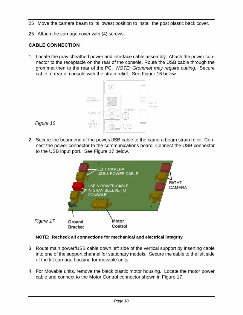
1. Locate the gray sheathed power and interface cable assembly. Attach the power con-nector to the receptacle on the rear of the console. Route the USB cable through thegrommet then to the rear of the PC. NOTE: Grommet may require cutting. Securecable to rear of console with the strain relief. See Figure 16 below.
2. Secure the beam end of the power/USB cable to the camera beam strain relief. Con-nect the power connector to the communications board. Connect the USB connectorto the USB input port. See Figure 17 below.
NOTE: Recheck all connections for mechanical and electrical integrity
3. Route main power/USB cable down left side of the vertical support by inserting cableinto one of the support channel for stationary models. Secure the cable to the left sideof the lift carriage housing for movable units.
4. For Movable units, remove the black plastic motor housing. Locate the motor powercable and connect to the Motor Control connector shown in Figure 17.
Figure 16
Figure 17
Page 19
Ultra™ Installation Instructions
SYSTEM START-UP AND CAMERA AIM
1. Power up the console and monitor and follow directions for initial software setup if notalready completed during console assembly. Software loading and initialization instruc-tions are part of the console assembly.
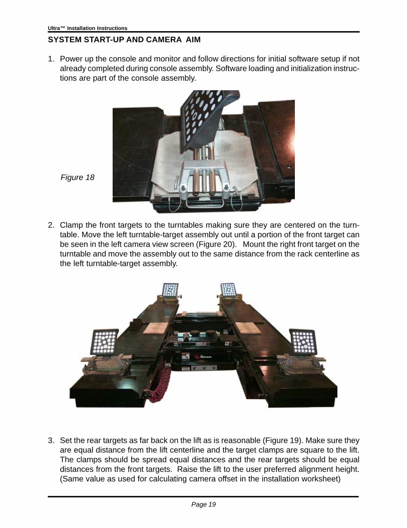
2. Clamp the front targets to the turntables making sure they are centered on the turn-table. Move the left turntable-target assembly out until a portion of the front target canbe seen in the left camera view screen (Figure 20). Mount the right front target on theturntable and move the assembly out to the same distance from the rack centerline asthe left turntable-target assembly.
3. Set the rear targets as far back on the lift as is reasonable (Figure 19). Make sure theyare equal distance from the lift centerline and the target clamps are square to the lift.The clamps should be spread equal distances and the rear targets should be equaldistances from the front targets. Raise the lift to the user preferred alignment height.(Same value as used for calculating camera offset in the installation worksheet)
Figure 18
Page 20
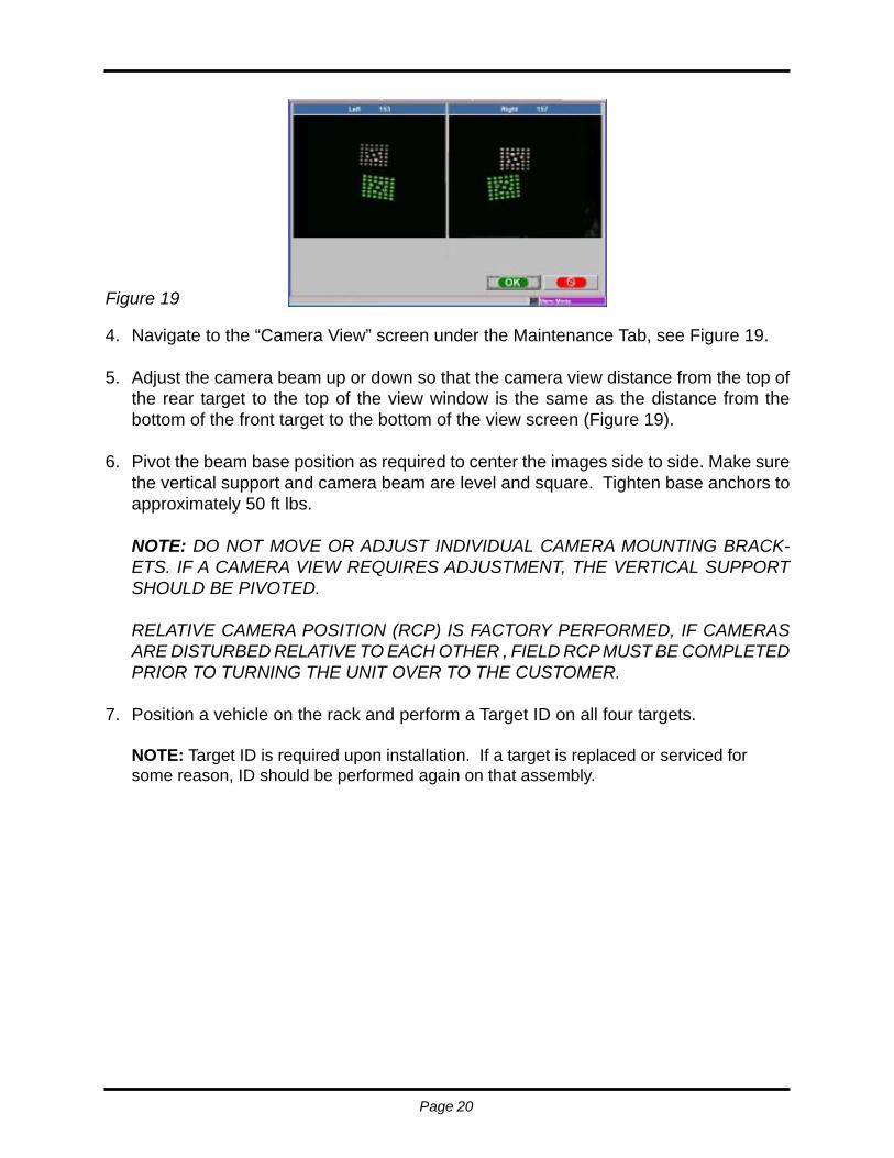
4. Navigate to the “Camera View” screen under the Maintenance Tab, see Figure 19.
5. Adjust the camera beam up or down so that the camera view distance from the top ofthe rear target to the top of the view window is the same as the distance from thebottom of the front target to the bottom of the view screen (Figure 19).
6. Pivot the beam base position as required to center the images side to side. Make surethe vertical support and camera beam are level and square. Tighten base anchors toapproximately 50 ft lbs.
NOTE: DO NOT MOVE OR ADJUST INDIVIDUAL CAMERA MOUNTING BRACK-ETS. IF A CAMERA VIEW REQUIRES ADJUSTMENT, THE VERTICAL SUPPORTSHOULD BE PIVOTED.
RELATIVE CAMERA POSITION (RCP) IS FACTORY PERFORMED, IF CAMERASARE DISTURBED RELATIVE TO EACH OTHER , FIELD RCP MUST BE COMPLETEDPRIOR TO TURNING THE UNIT OVER TO THE CUSTOMER.
7. Position a vehicle on the rack and perform a Target ID on all four targets.
NOTE: Target ID is required upon installation. If a target is replaced or serviced forsome reason, ID should be performed again on that assembly.
Figure 19
Page 21
Ultra™ Installation Instructions
SYSTEM TRAINING
Spend time with our new customer going over the software flow and operation of hisnew system. A few minutes here will save hours later for both you and the technician.Things to cover are outlined but not limited to the items below:
System features and specificationsProper system start-up and shut downWindows operation (if he has a desktop mode activated)Software navigationSetup, system interaction, preferences, featuresUsing WizardsPerform an alignmentNavigation of the Ultra™ Pro32 software features
ULTRA MOVABLE OPERATION INSTRUCTIONS
The movement of the camera beam is controlled from the aligner console keyboard.The lift drive mechanism is electronic and gets its power from the camera system;therefore no separate AC power connection is required. The Ultra camera lift inter-faces directly to the Ultra camera system central hub board, so the interface betweenthe aligner console and the camera system is the same as that on a fixed height Ultracamera system.
The lift controls are accessed by first pressing and holding the <CTRL> and <ALT>keys.
Then pressing and holding the up <↑> or down arrow <↓> on the keyboard will movethe camera lift up or down respectively as long as the keys are pressed or until thecamera beam reaches the upper or lower stops.
Releasing the keys will stop the camera beam motion.
When the keys <CTRL><ALT><↑> or <CTRL><ALT><↓> are pressed, the system willautomatically display the camera view screen to aid the operator with proper position-ing of the cameras.
If “Automatic Screen Advance” is enabled in Preferences/User Interaction/Features,the camera view screen will close after the “Timeout” period set for automatic screenadvance. Otherwise pressing the “OK” or “Cancel” buttons will close the camera viewscreen.
While in camera view, pressing the up arrow <↑> or down arrow <↓> alone will movethe camera beam in the corresponding direction.
Page 22
Camera beam movement is available from anywhere in the aligner software. Inaddition, a new shortcut key has been added to access camera view. Simplypressing the <−> key on the upper right of the number keypad will access thecamera view screen. See Figure 19.
Note: Some computer systems may use the <CTRL><ALT><↑/↓> sequence torotate the video display. In this case, the screen rotation must be disabled withinthe display properties of the graphic driver in Windows before using the UltraCamera Lift.
The camera lift may also be controlled from the wireless remote control. Pressingthe <*> key on the remote control will activate the camera view screen. While thecamera view screen is displayed, pressing the <↑> or <↓> on the remote control willmove the camera up or down respectively while the key is held. The sameoperation with regards to automatic screen advance applies for the remote controloperation.
The electronic drive system is designed to automatically stop when the upper andlower limits of its travel are reached. It will also stop if travel is interrupted in eitherdirection, such as lowering it on top of the console or other object.

Page 23
Ultra™ Installation Instructions

Ultra™ Installation Instructions
NOTES:

5908-5....01/20/2005..wdc... © copyright Snap-on Equipment 2005 Printed in the USATEEWA546A0


