Abstract: We propose a BBO-based chirped-pulse optical parametric am-plifier employing an angularly dispersed signal beam to yield a full-octavegain bandwidth, sufficient for the direct amplification of sub-10-fs pulses.Numerical simulations show that this power-scalable amplifier configurationhas a small-signal gain of 107 at a pumping intensity of 45 GW/cm2. Theadditional phase-matching flexibility compared to alternative configurationspermits the suppression of parasitic second harmonic generation of thesignal beam.
References and links1. S. Backus, C.G. Durfee, M.M. Murnane, and H.C. Kapteyn, “High power ultrafast lasers,” Rev. Sci. Instrum. 69,
1207-1223 (1998).2. M. Zavelani-Rossi, F. Lindner, C. Le Blanc, G. Cheriaux, and J.P. Chambaret, “Control of thermal effects for
high-intensity Ti:sapphire laser chains,” Appl. Phys. B 70, S193-S196 (2000).3. S. Sartania, Z. Cheng, M. Lenzner, G. Tempea, C. Spielmann, F. Krausz, and K. Ferencz, “Generation of 0.1-TW
5-fs optical pulses at a 1-kHz repetition rate,” Opt. Lett. 22, 1562-1564 (1997).4. J. Seres, A. Muller, E. Seres, K. O’Keeffe, M. Lenner, R.F. Herzog, D. Kaplan, C. Spielmann, and F. Krausz,
“Sub-10-fs, terawatt-scale Ti:sapphire laser system,” Opt. Lett. 28, 1832-1834 (2003).5. C.P. Hauri, M. Bruck, W. Kornelis, J. Biegert and U. Keller, “Generation of 14.8-fs pulses in a spatially dispersed
amplifier,” Opt. Lett. 29, 201-203 (2004).6. G. Cerullo, M. Nisoli, S. Stagira, and S. De Silvestri, “Sub-8-fs pulses from an ultra-broadband optical parametric
amplifier in the visible,” Opt. Lett. 23, 1283-1285 (1998).7. A. Shirakawa, I. Sakane, and T. Kobayashi, “Pulse-front-matched optical parametric amplification for sub-10-fs
pulse generation tunable in the visible and near infrared,” Opt. Lett. 23, 1292-1294 (1998).8. A. Baltuska, T. Fuji, and T. Kobayashi. “Visible pulse compression to 4 fs by optical parametric amplification
and programmable dispersion control,” Opt. Lett. 27, 306-308 (2002).9. E. Riedle, M. Beutter, S. Lochbrunner, J. Piel, S. Schenkl, S. Sporloein, and W. Zinth, “Generation of 10 to 50 fs
pulses tunable through all of the visible and the NIR,” Appl. Phys. B 71, 457-465 (2000).10. A. Dubietis, G. Jonusauskas, and A. Piskarskas, “Powerful femtosecond pulse generation by chirped and
(C) 2004 OSA 9 February 2004 / Vol. 12, No. 3 / OPTICS EXPRESS 518#3504 - $15.00 US Received 10 December 2003; revised 3 February 2004; accepted 3 February 2004
11. I.N. Ross, P. Matousek, M. Towrie, A.J. Langley, and J.L. Collier, “The prospects for ultrashort pulse durationand ultrahigh intensity using optical parametric chirped pulse amplifiers,” Opt. Commun. 144, 125-133 (1997).
12. X. Yang, Z. Xu, Y. Leng, H. Lu, L. Lin, Z. Zhang, R. Li, W. Zhang, D. Yin, and B. Tang, “Multiterawatt lasersystem based on optical parametric chirped pulse amplification,” Opt. Lett. 27, 1135-1137 (2002).
13. I.N. Ross, J. Collier, P. Matousek, C.N. Danson, N. Neely, R.M. Allott, D.A. Pepler, C. Hernandez-Gomez, andK. Osvay, “Generation of terawatt pulses by use of optical parametric chirped pulse amplification,” Appl. Opt.39, 2422-2427 (2000).
14. I. Jovanovic, C.A. Ebbers, B.C. Stuart, M.R. Hermann, and E.C. Morse, “Nondegenerate optical parametricchirped pulse amplification,” in Conference on Lasers and Electro-Optics , Vol. 73 of Trends in Optics andPhotonics , (Optical Society of America, Washington DC, 2002), pp. 387–388.
15. P. Di Trapani, A. Andreoni, C. Solcia, P. Foggi, R. Danielius, A. Dubietis, and A. Piskarskas, “Matching ofgroup velocities in three-wave parametric interaction with femtosecond pulses and application to traveling-wavegenerators,” J. Opt. Soc. Am. B 12, 2237-2244 (1995).
16. V.D. Volosov, S.G. Karpenko, N.E. Kornienko, and V.L. Strizhevskii, “Method for compensating the phase-matching dispersion in nonlinear optics,” Sov. J. Quantum Electron. 4, 1090-1098 (1975).
17. O.E. Martinez, “Achromatic phase matching for second harmonic generation of femtosecond pulses,” IEEE J.Quantum Electron. 25, 2464-2468 (1989).
18. G. Szabo and Z. Bor, “Broadband frequency doubler for femtosecond pulses,” Appl. Phys. B 50, 51-54 (1990).19. T.R. Zhang, H.R. Choo, and M.C. Downer, “Phase and group velocity matching for second harmonic generation
of femtosecond pulses,” Appl. Opt. 29, 3927-3933 (1990).20. A.V. Smith, “Group-velocity-matched three-wave mixing in birefringent crystals,” Opt. Lett. 26, 719-721 (2001).21. J. Piel, M. Beutter, and E. Riedle, “20–50-fs pulses tunable across the near infrared from a blue-pumped non-
collinear parametric amplifier,” Opt. Lett. 25, 180-182 (2000).22. K. Kato, “Second-harmonic generation to 2048 A in β -BaB2O4,” IEEE J. Quantum Electron. 22, 1013-1014
(1986).23. G.M. Gale, M. Cavallari, T.J. Driscoll, and F. Hache, “Sub-20-fs tunable pulses in the visible from an 82-MHz
optical parametric oscillator,” Opt. Lett. 20, 1562-1564 (1995).24. W.J. Alford and A.V. Smith, “Wavelength variation of the second-order nonlinear coefficients of KNbO3,
KTiOPO4, KTiOAsO4, LiNbO3, LiIO3, β -BaB2O4, KH2PO4, and LiB3O5 crystals: A test of Miller wavelengthscaling,” J. Opt. Soc. Am. B 19, 524-533 (2001).
25. J. Biegert, P. Schlup, C.P. Hauri, U. Keller and G. Arisholm, “Design of a sub-13-fs, multi-gigawatt chirped pulseoptical parametric amplification system,” to be published, (2004).
26. G. Arisholm. “General numerical methods for simulating second order nonlinear interactions in birefringentmedia,” J. Opt. Soc. Am. B 14, 2543-2549 (1997).
27. G. Arisholm, “Quantum noise initiation and macroscopic fluctuations in optical parametric oscillators,” J. Opt.Soc. Am. B 16, 117-127 (1999).
28. J. Biegert and J.C. Diels, “Compression of pulses of a few optical cycles through harmonic generation,” J. Opt.Soc. Am. B 18, 1218-1226 (2001).
29. F. Verluise, V. Laude, J.-P. Huignard, P. Tournois, and A. Migus, “Arbitrary dispersion control of ultrashort opticalpulses with acoustic waves,” J. Opt. Soc. Am. B 17, 138-145 (2000).
30. B. Schenkel, J. Biegert, U. Keller, C. Vozzi, M. Nisoli, G. Sansone, S. Stagira, S. De Silvestri, and O. Svelto,“Generation of 3.8-fs pulses from adaptive compression of a cascaded hollow fiber supercontinuum,” Opt. Lett.28, 1987-1989 (2003).
31. R. DeSalvo, A.A. Said, D.J. Hagan, E.W. van Stryland, and M. Sheik-Bahae, “Infrared to ultraviolet measure-ments of two-photon absorption and n2 in wide bandgap solids,” IEEE J. Quantum Electron. 32, 1324-1333(1996).
32. M. Sheik-Bahae and M. Ebrahimzadeh, “Measurements of nonlinear refraction in the second-order χ(2) materialsKTiOPO4, KNbO3, β -BaB2O4, and LiB3O5,” Opt. Commun. 142, 294-298 (1997).
1. Introduction
Chirped-pulse optical parametric amplifiers (CPOPAs) are increasingly showing promise asalternatives to chirped-pulse amplifier systems based on e.g. Ti:sapphire, which suffer fromgain narrowing [1] and thermal problems at high average powers unless they are cryogenicallycooled [2]. The large gain bandwidths of CPOPAs potentially allow the direct amplification ofsub-10 fs pulses, which are traditionally generated by spectral broadening in hollow fibers afterthe amplifier [3] or by spectral filtering between the amplifier stages [4]. Gain narrowing hasalso been overcome by using a spatially dispersed seed beam and tailoring the pump spatialdistribution to selectively amplify the spectral wings [5]. These techniques lead to complex
(C) 2004 OSA 9 February 2004 / Vol. 12, No. 3 / OPTICS EXPRESS 519#3504 - $15.00 US Received 10 December 2003; revised 3 February 2004; accepted 3 February 2004
system architectures and potentially reduce the amplification efficiency, and the output energyis ultimately limited by material absorption. By contrast, optical parametric amplifiers havenegligible thermal loads, high gain, potentially large bandwidths, and are scalable in terms ofpeak and average power. They have already proven useful for ultra-broadband amplificationof pulses at the µJ energy level, both in the visible and in the near-IR [6–9]. Chirped pulseOPAs (CPOPAs) [10, 11] have reached terawatt power levels for 1 µm pulses in the 100 fsregime [12, 13]. The CPOPA technique has also been applied in the wavelength range around800 nm [14], but the reported 60 fs pulse duration did not exploit the full potential of thetechnique. The tilting of pulse fronts, which is equivalent to angularly dispersing the beam (thisis explained in Section 3), has been exploited to match the group velocities of the pump andsignal beams in OPAs [7,15], and to increase the bandwidth with achromatic phase matching insecond harmonic generation (SHG) [16–19]. Group velocity matching of all beams in a generalthree-wave interaction using pulse front tilting has been studied theoretically [20]. In chirped-pulse amplifier systems, the pulses are relatively long and matching the group velocity of thepump is not of primary importance, so that the angular dispersion can be chosen to optimize theamplifier gain bandwidth. We are not aware of a detailed investigation of this technique appliedto CPOPAs.
In this paper we report a numerical study of a β -BaB2O4 (BBO)-based CPOPA, with angu-larly dispersed signal and idler beams to optimize the gain bandwidth. Our results show that itis possible to achieve a small-signal gain of > 107 and a full-octave bandwidth with realisticsystem parameters. An additional advantage of our configuration is that it does not suffer fromphase-matched parasitic SHG, which can be a problem in other BBO-based OPAs [21]. Theconditions for wide-band phase matching in BBO are formulated in Section 2, while a briefoverview of tilted pulse and phase fronts and our choice of modeling configurations are givenin Section 3. Our simulation results are presented in Section 4, and we draw conclusions inSection 5.
2. Wide-band phase matching
Energy conservation of a general three-wave interaction dictates that the angular frequenciesω j satisfy
ω3 = ω2 + ω1, (1)
where we define the indices j = 3, 2, and 1 to refer to the OPA pump, signal / seed, and idler,respectively. To first order, the frequency acceptance bandwidth of the nonlinear interactionwith respect to the signal frequency is determined by d∆k/dω 2, where ∆k = k3 −k2−k1 is thephase mismatch. We adopt the definition of the wave vectors k being orthogonal to the phasefronts with magnitude k(ω) = ω n(ω)/c, where n(ω) is the (dispersive) refractive index andc the vacuum velocity of light, and employ the Sellmeier equations of Kato [22], which arebased on measurements between 205 nm and 1064 nm. For a quasi-monochromatic pump, ω 3
is constant, and the signal acceptance bandwidth is given by
d∆kdω2
= − dk2
dω2− dk1
dω2= − dk2
dω2+
dk1
dω1. (2)
When this derivative vanishes, i.e. when the group velocities dk j/dω j of the signal and idlerare equal, the bandwidth becomes large, with the actual value being determined by higher orderderivatives.
As an example, it is well known that the bandwidth is large in degenerate collinear type 1interactions. In this case, the signal and idler beams are identical with equal group velocities.However, the equivalence of signal and idler beams makes this configuration phase-sensitiveand therefore not practical for broadband amplifiers. In a collinear phase matching geometry,
(C) 2004 OSA 9 February 2004 / Vol. 12, No. 3 / OPTICS EXPRESS 520#3504 - $15.00 US Received 10 December 2003; revised 3 February 2004; accepted 3 February 2004
the crystal orientation is selected to satisfy the phase matching conditions, and the crystal lengthto yield the desired gain, leaving no further design parameters to optimize the gain bandwidth.Noncollinear phase matching gives much greater scope for tailoring the bandwidth.
Although our simulation model is general, in the following examples we restrict our attentionto noncollinear interactions in the YZ crystal plane of BBO, where Z is the crystal optic axis,as shown in Fig. 1. The phase matching angle θ is defined as the polar angle between the opticaxis Z and the pump propagation vector k3. We denote the noncollinear angle between k2 andk3 by α . In addition to the crystal axes X, Y, and Z, we use a model coordinate system withaxes x, y, and z, where z is parallel to the pump beam and the model x axis lies in the crystalYZ plane. We take the crystal to be cut so that its face is perpendicular to the pump beam (andz axis). This choice has the advantage that, because of Snell’s law, the transverse componentsof a wave vector, kx and ky, remain constant across the crystal interface.
Fig. 1. Crystal axes X, Y, Z (green) and model axes x, y, z (black). The pump wave vectork3 is perpendicular to the crystal face and parallel to z. k2 (red) is the signal wave vectorwith internal noncollinear angle α .
The features of noncollinear phase matching in BBO can be explained by aid of Fig. 2.The figure shows the loci of noncollinear angles α , for different phase matching angles θ , forwhich phase matching is satisfied. Perfect phase matching with an angularly dispersed signalbeam could be achieved across the entire bandwidth if α(ω) at each seed frequency ω could bemade to follow one of the curves. Creating such an arbitrary angular dispersion is difficult, sowe focus our attention to two forms of noncollinear phase matching: a collimated signal beamtilted with respect to the pump beam (horizontal lines in Fig. 2); and a signal beam additionallydispersed by a diffraction grating (lines of constant slope).
3. Pulse-front tilting
The numerical simulation uses a transverse wavenumber k x(ω) representation for each fre-quency component to efficiently handle tilted beams, wave-, and pulse-fronts. The trans-verse wavenumber and noncollinear angle α(ω) are geometrically related by sin[α(ω)] =kx(ω)/|k(ω)|. Because of our choice of coordinate system and crystal cut, k x is the same insideand outside the crystal, although the noncollinear angle is changed by refraction.
Figure 3(a) shows the k vectors for the central frequency (black) as well as two extremefrequencies components (blue, red) in the case of a collimated signal beam. Tilting the entirebeam relative to the pump vector yields a noncollinear angle α that is constant for all frequen-cies. Phase matching results in a dispersed idler even though the seed beam is collimated. Aconstant α corresponds to a horizontal line in Fig. 2; when such a line is tangent to a phasematching curve, ∆k becomes independent of wavelength to first order (matched group veloc-
(C) 2004 OSA 9 February 2004 / Vol. 12, No. 3 / OPTICS EXPRESS 521#3504 - $15.00 US Received 10 December 2003; revised 3 February 2004; accepted 3 February 2004
400 600 800 1000 12000
50
100
150
200
250θ = 0.69 rad
0.60
0.55
0.52
0.51
λ3 = 400 nm
WL
(ii)
(i)
pSHG
Signal Wavelength (nm)
α (m
rad)
Fig. 2. Phase-matching curves for noncollinear type 1 (ooe) interactions in BBO with apump wavelength of 400 nm. Each black curve shows the loci of perfect phase matching(∆k = 0) for a specific value of θ , while the green line shows wavelengths at which parasiticsecond harmonic generation is phase matched. The broadband phase matching configura-tion that has previously been used for white-light seeded OPAs is shown in red (WL). Theconfigurations marked in blue are investigated in this paper.
KG
Grating
(b)(a)
α
Signal
Pump
IdlerSeed
Mirrorz
x
^
^
Fig. 3. (a) Tilted collimated beam and (b) angularly dispersed beam in model xz plane. (a)The seed beam (solid lines) is tilted by noncollinear angle α , constant for all wavelengths(blue, red), and interacts with a monochromatic pump (green) to yield a dispersed idler(dashed). (b) Influence of diffraction grating adding constant KG to all frequency compo-nents, resulting in a tilted pulse relative to the central k (black). KG is the grating vector.
ities for signal and idler) and gives a broad gain bandwidth. When a phase matching curve isapproximately horizontal over an extended range of wavelengths, the second order derivativeof the phase mismatch is also small and good phase matching can be achieved across the wholerange. One such configuration, which has been exploited in many experiments [6, 7, 23], is theflat section between 550 nm and 700 nm (red line in Fig. 2) for θ = 0.55rad and α = 66mrad(3.7◦).
Figure 3(b) shows the influence of diffraction off a grating in the x axis. Mathematically, agrating with groove spacing Λ multiplies the pulse envelope by exp(iK Gx), where the gratingvector KG = 2π/Λ, which is equivalent to imposing a constant transverse wave vector compo-nent KG on all frequency components. The pulse front (which is determined by the intensitydistribution) is not affected, resulting in a signal with a pulse front tilted relative to the cen-tral beam direction (black). The frequency-dependent noncollinear angle in the crystal can bewritten as α(ω) = sin−1(λ/(nΛ)) ≈ λ/(nΛ) for small diffraction angles. The equivalence ofangular dispersion and a tilted pulse front is illustrated in Fig. 4. Phase matching results in allidler components having transverse wave vector components of k x = −KG, and, in the generalcase, both the signal and idler beams are angularly dispersed.
(C) 2004 OSA 9 February 2004 / Vol. 12, No. 3 / OPTICS EXPRESS 522#3504 - $15.00 US Received 10 December 2003; revised 3 February 2004; accepted 3 February 2004
t
x
(a)
ω
k x
(b)
t
x
(c)
ω
k x
(d)
Fig. 4. Equivalence of angular dispersion and pulse tilt. (a) Untilted pulse envelope,E (x,t), where x is normal to the propagation direction. (b) Fourier transform E(kx,ω) =∫ ∫
E (x,t)exp(i(ωt − kxx))dxdt. (c) Tilted pulse E ′(x,t) = E (ax− bct,at + bx/c), wherec is the velocity of light and a and b are rotation coefficients that satisfy a2 + b2 = 1.(d) Fourier transform of the tilted pulse, which can be shown to be E ′(kx,ω) = E(akx +bω/c,aω −bckx). The angular dispersion is reflected by the variation of kx with ω .
The approximately linear relation between α and λ means that beams tilted and dispersed bya grating correspond to straight sloping lines in Fig. 2. A suitable combination of beam tilt andgrating dispersion can thus be chosen to phase match a wavelength range over which the phasematching curve has a constant slope. Since the curves in Fig. 2 have constant slopes that covermuch wider and more diverse wavelength ranges than the horizontal sections, angular disper-sion offers greater flexibility in phase matching broadband beams. The approximate relationbetween α and λ can only be used to identify potential broadband phase matching configura-tions; in the final phase matching calculations below we use the exact relation for k x. For anangularly dispersed beam with fixed kx, the projection of the group velocity onto the z-directionis given by
vg,z =(
dkz
dω
)−1
= vg cos [α(ω)] , (3)
where vg is the group velocity parallel to k.Although the phase mismatch is the most important factor determining the bandwidth, it is
necessary to calculate the actual gain to analyze an interaction in detail. The small-signal gaincoefficient g in the presence of a phase mismatch ∆k is given by
g =
√γ2ω1ω2I3 −
(∆k2
)2
, (4)
where
γ =χeff
c
√Z0
2n1n2n3, (5)
χeff = 2deff is the effective nonlinear susceptibility, and Z0 is the vacuum impedance. Equa-tion (4) shows that the tolerance to phase mismatch increases with gain and can be estimatedby |∆k| � g0, where g0 is the gain coefficient in the absence of phase mismatch. Furthermore,the gain depends on frequency through the factor (ω 2ω1)1/2 = [ω2 (ω3 −ω2)]1/2, which, for afixed range of variation for ω2, varies least if the center frequency equals ω3/2.
We are interested in broadband amplification around 800 nm with a 400 nm pump, so weidentify two potential configurations marked in Fig. 2: (i) θ = 0.51rad and α = 16mrad witha collimated signal beam; and (ii) θ = 0.69rad and angular dispersion with k x = 2106mm−1
(kx has the same value inside and outside the crystal, as explained above). Other configura-tions are also possible, but these two were found to give maximum bandwidth for the cases
(C) 2004 OSA 9 February 2004 / Vol. 12, No. 3 / OPTICS EXPRESS 523#3504 - $15.00 US Received 10 December 2003; revised 3 February 2004; accepted 3 February 2004
with collimated and angularly dispersed signals, respectively. For type 1 phase matching inBBO, propagation in the YZ plane gives the maximum nonlinear coefficient, d eff = dyxx cosθ .|dyxx| = |dyyy| because of Kleinman symmetry, and dyyy = 2.2pm/V [24]. For the gain calcula-tions we take a pump intensity of 45 GW/cm2, which gives g0 in the range 3.5–4.1 mm−1 forour configurations. To get comparable results we adjust the crystal length L c to obtain a peakgain of about 108 in each case. We analyzed these configurations by plotting the phase mis-match ∆k = |∆k|sign(∆k ·k3) and small-signal gain g as functions of frequency, and optimizedthem by fine-tuning the crystal orientation and noncollinear parameters. The results are shownin Figs. 5 and 6.
For case (i) (Fig. 5), the central 800 nm wavelength is phase matched with a noncollinearangle of α = 10mrad (black line). Increasing the noncollinear angle to α = 16mrad (red) givesa greater gain bandwidth, as can be seen in Fig. 5(b); but increasing α further to 22 mrad(green) results in a significant dip of the gain at the center frequency. Detailed simulations ofthis configuration were recently reported for a CPOPA system based on measured 12 fs seedpulses [25].
−5
0
5
300 350 400 450Frequency (THz)
700800900Wavelength (nm)
∆ k
(mm
−1 )
(a)
7
8
300 350 400 450Frequency (THz)
700800900Wavelength (nm)
Log 10
(Gai
n)
(b)
Fig. 5. (a) Phase mismatch ∆k; and (b) gain; as functions of signal frequency ω2 for λ3 =400nm, θ = 0.51, and Lc = 2.5mm. α = 10mrad (black), α = 16.2mrad (red), and α =22.3mrad (green).
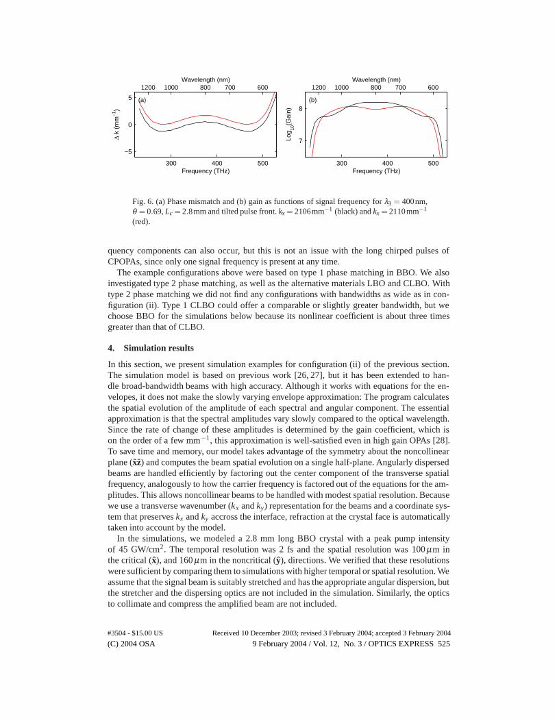
In configuration (ii), kx is constant, so α is approximately proportional to λ . Since the signaland idler have the same polarization, opposite kx, and both are centered at the degenerate wave-length, there is a complete symmetry between the two. Figure 6 shows the phase mismatch andgain for two different values for kx. With kx = 2106mm−1 (black curve), we find a bandwidthfrom 600 to 1200 nm, constant to within half an order of magnitude. The central peak is dueto the frequency factor in the gain coefficient. The gain curve can be flattened by changing thephase mismatch to kx = 2110mm−1 (red), but this reduces the bandwidth slightly, as seen inFig. 6 (b). These kx dispersions correspond to diffraction off gratings with around 330 lines permm.
An additional flexibility provided by phase matching with a dispersed seed beam is the sup-pression of parasitic SHG of the signal, which has been observed in other type 1 phase-matchedBBO-based broadband OPAs [21]. The phase matching angles for collinear SHG in BBO atwavelengths of interest to the configurations investigated here are shown by the green line inFig. 2. In the simple noncollinear phase matching of case (i), parasitic SHG at around 800 nm isphase matched and could potentially distort the amplified spectrum and reduce the conversionefficiency. By contrast, in configuration (ii) with θ ≈ 0.7rad, phase matched SHG is possibleonly for wavelengths shorter than 600 nm, which lie outside the gain bandwidth (see Fig. 6).In general wide-band OPAs, parasitic sum frequency generation (SFG) of different signal fre-
(C) 2004 OSA 9 February 2004 / Vol. 12, No. 3 / OPTICS EXPRESS 524#3504 - $15.00 US Received 10 December 2003; revised 3 February 2004; accepted 3 February 2004
−5
0
5
300 400 500Frequency (THz)
60070080010001200Wavelength (nm)
∆ k
(mm
−1 )
(a)
7
8
300 400 500Frequency (THz)
60070080010001200Wavelength (nm)
Log 10
(Gai
n)
(b)
Fig. 6. (a) Phase mismatch and (b) gain as functions of signal frequency for λ3 = 400nm,θ = 0.69, Lc = 2.8mm and tilted pulse front. kx = 2106mm−1 (black) and kx = 2110mm−1
(red).
quency components can also occur, but this is not an issue with the long chirped pulses ofCPOPAs, since only one signal frequency is present at any time.
The example configurations above were based on type 1 phase matching in BBO. We alsoinvestigated type 2 phase matching, as well as the alternative materials LBO and CLBO. Withtype 2 phase matching we did not find any configurations with bandwidths as wide as in con-figuration (ii). Type 1 CLBO could offer a comparable or slightly greater bandwidth, but wechoose BBO for the simulations below because its nonlinear coefficient is about three timesgreater than that of CLBO.
4. Simulation results
In this section, we present simulation examples for configuration (ii) of the previous section.The simulation model is based on previous work [26, 27], but it has been extended to han-dle broad-bandwidth beams with high accuracy. Although it works with equations for the en-velopes, it does not make the slowly varying envelope approximation: The program calculatesthe spatial evolution of the amplitude of each spectral and angular component. The essentialapproximation is that the spectral amplitudes vary slowly compared to the optical wavelength.Since the rate of change of these amplitudes is determined by the gain coefficient, which ison the order of a few mm−1, this approximation is well-satisfied even in high gain OPAs [28].To save time and memory, our model takes advantage of the symmetry about the noncollinearplane (xz) and computes the beam spatial evolution on a single half-plane. Angularly dispersedbeams are handled efficiently by factoring out the center component of the transverse spatialfrequency, analogously to how the carrier frequency is factored out of the equations for the am-plitudes. This allows noncollinear beams to be handled with modest spatial resolution. Becausewe use a transverse wavenumber (kx and ky) representation for the beams and a coordinate sys-tem that preserves kx and ky accross the interface, refraction at the crystal face is automaticallytaken into account by the model.
In the simulations, we modeled a 2.8 mm long BBO crystal with a peak pump intensityof 45 GW/cm2. The temporal resolution was 2 fs and the spatial resolution was 100 µm inthe critical (x), and 160 µm in the noncritical (y), directions. We verified that these resolutionswere sufficient by comparing them to simulations with higher temporal or spatial resolution. Weassume that the signal beam is suitably stretched and has the appropriate angular dispersion, butthe stretcher and the dispersing optics are not included in the simulation. Similarly, the opticsto collimate and compress the amplified beam are not included.
(C) 2004 OSA 9 February 2004 / Vol. 12, No. 3 / OPTICS EXPRESS 525#3504 - $15.00 US Received 10 December 2003; revised 3 February 2004; accepted 3 February 2004
We first investigated some idealized configurations by simulating in a single transverse di-mension using simulated pump and seed pulses to study the output spectra qualitatively. Theseed pulse had an order-12 super-Gaussian intensity envelope of length 3 ps (1/e 2 full-width),shown by the black line in Fig. 7(a). It was chirped with a chirp parameter of 4×10 −4 rad/fs2,corresponding to a stretched-pulse spectrum ranging from 580 nm to 1300 nm (black line inFig. 7(b)). To ensure that the whole signal pulse interacts with the same pump intensity, andto allow for temporal walk-off and the rounded corners of the pump pulse envelope, the pumpwas chosen to have a 5 ps long, order-12 super-Gaussian intensity envelope. The spatial dis-tributions of both beams were super-Gaussian of order 10, with 1/e 2 radii of 1 mm. The widthof the suppressed transverse dimension was taken to be 1 mm, and the pump energy is 3.6 mJ.
1 2 3 4 50
0.5
1
Time (ps)
Nor
m. p
ower
(a)
0
0.5
1
200 300 400 500 600Frequency (THz)
50060080010001500Wavelength (nm)
Nor
mal
ized
spe
ctra
l pow
er
(b)
0
0.5
1
200 300 400 500 600Frequency (THz)
50060080010001500Wavelength (nm)
Nor
mal
ized
spe
ctra
l pow
er
(c)
Fig. 7. (a) Normalized seed power (black) and output signals for seed intensity 10 W/cm2
(red dashed) and 1000 W/cm2 (red solid). (b) Spectra of seed (black), signal (red) and idler(green) for a positively chirped seed pulse. The seed intensity is 10 W/cm2 (dashed) or1000 W/cm2 (solid). (c) Signal and idler spectra for a negatively chirped seed.
Figure 7(a) shows the normalized seed pulse and output signal pulses for two different seedintensities, 10 W/cm2 (0.48 pJ, dashed lines) and 1000 W/cm2 (48 pJ, solid lines). Figure 7(b)and (c) show the signal and idler spectra for the same two seed intensities, with positive ornegative sign of the chirp, respectively. At the modest peak seed intensity of 10 W/cm 2, pumpdepletion is small and the amplification of the signal spectrum is approximately proportional tothe gain spectrum in Fig. 6, independently of the sign of the chirp. The idler spectrum (dashedgreen) is skewed towards short idler wavelengths. The nonlinear interaction results in the gen-eration of signal and idler photons in pairs; since the flat seed spectrum (solid black) comprisesmore low-frequency signal photons, more high-frequency idler photons are generated in theamplification process.
At a higher seed intensity of 1000 W/cm2, the shape of the spectra is determined principallyby the limiting effect of pump depletion rather than by the seed spectrum and small-signal gain.Due to the dispersive characteristics of BBO, both high and low frequency wings of the seedspectrum travel more slowly than does the central frequency (see Fig. 8) and thus experience
(C) 2004 OSA 9 February 2004 / Vol. 12, No. 3 / OPTICS EXPRESS 526#3504 - $15.00 US Received 10 December 2003; revised 3 February 2004; accepted 3 February 2004
temporal walkoff relative to the pump pulse. For the seed stretched in a positive-dispersivematerial, the low signal frequency components in the leading edge of the pulse interact withsuccessively later parts of the pump pulse that have already been depleted. By contrast, thehigh frequency trailing edge continually interacts with undepleted parts of the pump and thusexperiences higher gain, which gives rise to the signal spectrum skewed towards the high fre-quency end (Fig. 7(b), solid red line). This mechanism works oppositely for the idler because ithas the opposite chirp of the signal. If the sign of the seed chirp is reversed, the qualitative fea-tures of the signal and idler spectra at high seed power are reversed also, as shown in Fig. 7(c).The relatively flat signal spectrum in this case may be an advantage in some applications, butin the remaining examples we assume a positive seed chirp, as is common in chirped-pulseamplifiers. The output signal energy is 0.68 mJ, which corresponds to a conversion efficiencyinto the signal of 19%. In all cases, the amplification bandwidth exceeds one octave.
1.68
1.70
1.72
1.74
300 400 500Frequency (THz)
60070080010001200Wavelength (nm)
Gro
up in
dex
c/v g
ng,o
ng,z
ng,pump
Fig. 8. Signal group velocity index as a function of frequency for configuration (ii). Theblue line shows the group index for the ordinary (slow) polarization in BBO, while thered line shows the effective group index in the z-direction calculated using Eq. (3). Theapproximate symmetry of ng,z around the degenerate frequency (375 THz) reflects wide-band phase matching. The ng,3 = 1.716 group index of the pump beam is shown by thegreen line.
In order to obtain a more realistic estimate for the conversion efficiency, we extended thesimulation to include both transverse dimensions. We used pulses with the same parametersas above, but reduced the pump pulse duration to 4 ps to improve the conversion efficiency.Figure 9(a) shows the input and output pulse shapes. For an input pump energy of 4 mJ(45 GW/cm2), a seed energy of 67 pJ yielded 0.82 mJ of amplified signal output This cor-responds to a signal gain of 107 and a conversion efficiency into the signal of 20%. The inputand output signal spectra, which have the same qualitative features as discussed above, areshown in Fig. 9(b).
Figure 9(c) shows the fluence distribution of the output signal beam; it is round and undis-torted at this moderate conversion efficiency. The small asymmetry and offset from the modelorigin in the horizontal direction is due to the noncollinearity and the Poynting vector walk-offof the pump. Figure 9(d) shows the far-field in the x-direction as a function of wavelength forthe seed and output signal. Apart from the overall change of the spectrum, the far field is wellpreserved in the output. This implies that the output beam has the same angular dispersion asthe input beam, allowing it to be recollimated by an optical arrangement identical to that whichdispersed the seed.
The spectral phase of the central spatial element of the output beam, relative to the phaseof a beam that has propagated passively through the crystal, is shown in Fig. 9(e). The nonlin-ear mixing introduces a phase shift because of the nonzero phase-mismatch. This phase shiftmust be compensated for the compressed pulses to approach the transform limit, shown by the
(C) 2004 OSA 9 February 2004 / Vol. 12, No. 3 / OPTICS EXPRESS 527#3504 - $15.00 US Received 10 December 2003; revised 3 February 2004; accepted 3 February 2004
0 2 4 60
500
1000
Time (ps)
Pow
er (
MW
)(a)
0
2
4
200 300 400 500Frequency (THz)
60070080010001500Wavelength (nm)
Nor
mal
ized
spe
ctra
l pow
er
(b)
−1 0 1
−1
0
1
Position x (mm)
Pos
ition
y (
mm
)
(c)
2100
2105
2110
200 300 400 500Frequency (THz)
k x (m
m−
1 )
Output signal2100
2105
2110
60070080010001300Wavelength (nm)
k x (m
m−
1 )
(d) Seed
−3
0
3
200 300 400 500Frequency (THz)
60070080010001300Wavelength (nm)
Spe
ctra
l pha
se (
rad) (e)
−10 0 10 200
0.5
1
Time (fs)
Nor
mal
ized
pow
er (f)
Fig. 9. Simulation results for idealized super-Gaussian beams. (a) Temporal profiles ofthe input pump (blue dashed), output pump (blue solid), input seed (107 times magnified,black), output signal (red), and idler (green). (b) Spectra of seed (107 times magnified,black), output signal (red), and idler (green). (c) Contours of output signal fluence distribu-tion. (d) Far-field spectra for the x-direction (noncollinear direction) of the seed (upper)and output signal (lower). The dashed lines show the center kx values. (e) Spectral phaseof output signal relative to a passively propagated beam. (f) Transform limited pulses cor-responding to the seed spectrum (black) and output signal spectrum (red). Their durationsare 2.4 fs and 3.3 fs (FWHM), respectively. The blue curve shows the pulse correspondingto the output signal spectrum and the nonlinear phase distortion from (e).
(C) 2004 OSA 9 February 2004 / Vol. 12, No. 3 / OPTICS EXPRESS 528#3504 - $15.00 US Received 10 December 2003; revised 3 February 2004; accepted 3 February 2004
red line in Fig. 9(f); if the phase is left uncompensated, the compressed pulse is longer andhas significant pre- and post-pulses (blue line). For comparison, the transform limited pulsecorresponding to the seed spectrum is shown by the black line. Since the spectral phase is well-behaved, we anticipate that such compensation is possible using a spectral shaper or acousto-optic dispersive filter (DAZZLER) [29].
Lastly, we exploited the full potential of the numerical simulation by modeling a measuredseed pulse. We modified the pump beam to have Gaussian spatial and temporal profiles, butmaintained the 1 mm 1/e2 waist radius and the 4 ps pulse duration (full width to 1/e 2). Thepeak pump intensity was 45 GW/cm2, as above, which corresponded to an energy of 1.7 mJ.The complex seed temporal envelope was taken from a SPIDER measurement of a real 3.8 fs(FWHM) pulse obtained by compressing the output from a hollow fiber [30]. The pulse wasstretched by numerical propagation through a 10 mm block of SF5 glass, taking all dispersionorders into account, making its length comparable to that of the pump pulse. The seed beamtransverse profile was Gaussian with 1 mm radius, matching that of the pump. Figure 10 showsthe results. For a seed energy of 0.6 nJ we obtained 190 µJ of amplified output, which cor-responds to 11% conversion efficiency. As mentioned previously, there exists some trade-offbetween conversion efficiency and spectral gain bandwidth in the wings of the stretched seedpulse. The seed energy in this example was chosen an order of magnitude greater than in theprevious example in order to enhance conversion in the (spatial and temporal) wings of thepump pulse.
0 2 4 60
400
800
Time (ps)
Pow
er (
MW
)
(a)
0
1
2
300 400 500Frequency (THz)
60070080010001300Wavelength (nm)
Nor
mal
ized
spe
ctra
l pow
er
(b)
−3
0
3
300 400 500Frequency (THz)
600700800900Wavelength (nm)
Spe
ctra
l pha
se (
rad) (c)
−10 0 10 200
0.5
1
Time (fs)
Nor
mal
ized
pow
er (d)
Fig. 10. Results for a measured seed pulse, Gaussian pump pulse, and Gaussian spatialprofiles. (a) Temporal profiles of the input pump (blue dashed), output pump (blue solid),input seed (3× 10⁵ times magnified) (black), output signal (red), and idler (green). (b)Spectra of seed (3×10⁵ times magnified) (black), output signal (red), and idler (green). (c)Spectral phase of output signal relative to a passively propagated beam with n2 = 0 (red)and n2 = 10−15 cm2/W (blue). The green curve shows the rapid part of the phase variationalone. (d) Transform limited seed (black) and signal (red) pulses. The blue curve shows thepulse corresponding to the output signal spectrum and the nonlinear phase distortion (thered line in (c)).
(C) 2004 OSA 9 February 2004 / Vol. 12, No. 3 / OPTICS EXPRESS 529#3504 - $15.00 US Received 10 December 2003; revised 3 February 2004; accepted 3 February 2004
The seed spectrum, shown as the black line in Fig. 10(b), is not optimally matched to theOPA because it is centered below 800 nm and extends below 600 nm, but it is neverthelessamplified with only small spectral clipping, yielding the spectrum shown in red in Fig. 10(b).Figure 10(c) shows the spectral phase relative to a passively propagated beam. With this phaseleft uncompensated, the pulse shown by the blue line in Fig. 10(d) is obtained. The transformlimit of the amplified spectrum (red) indicates that with these realistic parameters, the CPOPAcan support pulses as short as 5.2 fs.
The slow variation in spectral phase is similar to that of the idealized pulses discussed above,but there is now some additional rapid variation. The latter could be eliminated numerically byreducing the seed power, which reduced the nonuniform pump depletion caused by the rapidlyvarying signal power. Compression of a pulse with only the rapid phase variations (green linein Fig. 10(c)) yields almost the transform limit, from which we conclude that the broadening ofthe blue pulse is primarily caused by the slow phase variation.
Including a nonlinear refractive index n 2 to investigate possible self-phase modulation, lead-ing to additional spectral broadening, we found that the effect of n 2 was very small, and theresulting spectral phase differed only negligibly, as seen from the blue line in Fig. 10(c). Thevalue of n2 = 10−15cm2/W used was a conservative estimate because it is higher than the valuesmeasured for BBO [31, 32] by a factor 2 or 3.
5. Conclusions
We have investigated broadband phase matching of a CPOPA by spectrally dispersing the seedbeam. We could use the freedom of tilting the pulse fronts to match the group velocities ofsignal and idler, since the relatively long pulses of chirped pulse amplification alleviate theneed for precisely matched pump and signal velocities using pulse-front tilting. By using thistechnique and considering a number of possible noncollinear phase matching configurationsin BBO, we have identified one that gives an octave gain bandwidth from about 600 nm to1200 nm when pumping at 400 nm. Detailed numerical simulations of a measured 3.8 fs seedpulse show an output spectrum of about 200 THz width, corresponding a transform limit of5.2 fs, although the measured spectrum was poorly matched to the CPOPA gain and did notexploit the full bandwidth. With 1.7 mJ pump energy (45 GW/cm 2) and a 2.8 mm long BBOcrystal, the seed pulses were amplified from 0.6 nJ to 190 µJ, corresponding to a gain of 3×10 5.Using idealized pulses, the model results showed pump depletions as high as 40%, and gainsof 107 across the whole octave. The configuration chosen has the additional advantage that thegeneration of parasitic second harmonic is not phase matched.
In the simulation examples we assumed modest pump energies, which currently pose a lim-itation on experimental CPOPA systems. This does not represent the limit of CPOPA, whosepulse energy can be scaled by making the pulses longer or the beams wider. Such scalinghas beneficial side-effects: Longer pulses reduce the influence of temporal walk-off, and widerbeams make the spatial walk-off caused by the Poynting vector walkoff and noncollinearity lessimportant. The principles of broadband phase matching by angular dispersion investigated hereare quite general and can, in principle, be applied to any wavelength range, provided a suitablecombination of nonlinear crystal and pump can be found.
Acknowledgments
We thank Gunnar Rustad for useful comments.
(C) 2004 OSA 9 February 2004 / Vol. 12, No. 3 / OPTICS EXPRESS 530#3504 - $15.00 US Received 10 December 2003; revised 3 February 2004; accepted 3 February 2004