23
1 Ultra High Molecular Weight Polyethylene (UHMWPE) pipes for pressure applications

1
Ultra High Molecular Weight
Polyethylene (UHMWPE)
pipes for pressure
applications
2
PREFACE
This draft standard was prepared by Eugene Lakous of Pipe & Buoy Australia Pty. Ltd. In conjunction
with data derived from the Chinese standard QB/T 2668-2008
This revision is consistent with ISO 11542-1, “Plastics – Ultra-high-molecular-weight-polyethylene
(PE-UHMW) moulding and extrusion materials –“
Relevant testing and use will be expanded upon within the standard.

3
CONTENTS
Foreword pg 4
Scope pg 6
Normative References pg 6
Defintions pg 7
Nomenclature pg 8
Classification pg 8
Product Specification pg 8
Geometry pg 12
Testing methods pg 15
Appendix A pg 18
Appendix B pg 21
4
FOREWORD
This manual is based on data derived from the production and use of UHMWPE by the
manufacturers accredited to ISO 9001 and 14001. It is in accordance with all known data of
UHMWPE characteristics, verified against performance tests by said manufacturers.
Appendices A and B are to be used as supplementary test methodologies that contribute to our
knowledge of UHMWPE performance and subsequent expectations of pipe suitability.
Q: Why should Australia use UHMWPE Pipes?
A1. Longer Life
With a wear resistance 4 to 7 greater than Q235 Steel or HDPE and 2.7 times that of 16Mn Steel under the same operating conditions, UHMWPE Pipe will give you far superior life under most operating conditions.*
A2. Non-Scaling
Because of it's very smooth surface and self lubricating properties UHMWPE Pipe has far superior anti-scaling properties to any other pipeline on the market today.
A3. Less Maintenance Costs, Less Maintenance Time
The far superior wear resistance of UHMWPE pipe will significantly increase the time between pipe replacements and/or rotations resulting in massive savings in the way of reduced maintenance costs and time.
A4. Less Downtime, Less Lost Production
The far superior wear resistance of UHMWPE pipe will significantly increase the time between pipe replacements and/or rotations resulting in massive savings in the way of less downtime for maintenance and less loss of plant production time.
A5. Reduced Pumping Costs
Along with the benefits mentioned above UHMWPE Pipes also offer significant cost savings through increased pumping efficiency.
With a surface roughness of 0.00022mm UHMWPE Pipe is extremely smooth and has self lubricating properties superior to PTFE (Teflon).
This means less friction, less pressure loss and greatly reduced energy inputs to deliver the same result.
5
A6. Chemical and Corrosion Resistance
With chemical resistance second only to PTFE (Teflon), UHMWPE pipe will offer superior life to other pipeline products in chemically aggressive or corrosive applications under most operating conditions. *
A7. Extremely High Impact Resistance
UHMWPE has the highest impact resistance of any plastic. UHMWPE is widely used in the production of Bullet Proof Vests and Bullet Proof Helmets.
A8. Environmentally Friendly
Base material is colourless, odourless and non-toxic. Low Carbon Production Process. The UHMWPE manufacturing process produces only 15% of
the carbon dioxide emissions of that of the equivalent amount of steel pipe without discharge of waste water, exhausted gas and waste residue.
No painting.
6
Ultra High Molecular Weight Polyethylene
(UHMWPE) pipes for pressure applications
1 SCOPE AND APPLICATION
1.1 Scope
This Standard specifies requirements for ultra high molecular weight polyethylene pipes for the conveyance of
fluids under pressure and/or solids. Such media includes, but is not restricted to: water, wastewater, brine,
slurries, acids, powders, pastes, and abrasive particulates.
Further, this standard specifies UHMWPE pipe classification; referencing raw material distinction, product
specification, testing methods, testing regulations, and methods of storage.
1.2 Application
Means for demonstrating compliance with this Standard shall be in accordance with ISO 9001 and 14001,
utilising testing referenced in Appendix A and B.
The test requirements may be achieved by alternative test methods if such methods can be shown to provide
equal or greater accuracy than those specified herein. In all cases of dispute, the methods specified in this
Standard shall be considered the reference test methods.
2 NORMATIVE REFERENCES
The following documents are relevant to the application of this standard. They are all based on ISO standard.
GB/T 1043-1993 Impact strength determination of rigid materials with the use of a Charpy
test - Plastics (ISO 179: 1982)
GB/T 2828.1-2003 Lot Inspection Sampling Plan (ISO 2859-1: 1999)
GB/T 2918-1998 Testing plastic samples. Condition standard, environmentally approved
(ISO 6259-3: 1997)
GB/T 6111-2003 Method of testing inner pipe pressure of thermoplastics
(ISO 1167: 1996)
GB/T 6671-2001 Thermoplastic pipe longitudinal shrink rate (ISO 2505: 1994)
GB/T 8804.3-2003 Tensile testing of thermoplastic pipe (ISO6259-3: 1997)
GB/T 8806-1998 Method for testing plastic pipe length (ISO 3126: 1974)
GB/T 17219-1998 Safety standards for drinkable water distribution equipment
GB/T 17391-1998 Method of testing thermal stability of polyethylene pipe
(ISO/TR 10837: 1991)
ISO 11542-1:2001 PE-UHMW moulding and extrusion material
7
3 DEFINITIONS
3.1 Brittle Failure
The type of failure of the materials in pipe form during pressure testing, where the pipe exhibits no plastic
deformation visible to the naked eye (normal or corrected vision).
3.2 Co-extruded jacket pipes
A pipe comprising two layers, where the layers are bonded simultaneously in a die head as part of the
extrusion process.
3.3 Ductile mode
The type of failure of the material in pipe form during pressure testing, where the pipe exhibits
plastic deformation visible to the naked eye (normal or corrected).
3.4 Hoop stress
The stress in a pipe or fitting under pressure acting tangentially to the perimeter of a transverse section.
3.5 Hydrostatic design stress (HDS)
Hoop stress due to intenral hydrostatic pressure, which can be applied continuously at a specified
temperature, and which is obtained by the application of a design factor to the minimum required strength
(MRS)
3.6 Maximum allowable operating pressure (MAOP)
The maximum pressure that can be sustained, with a design factor, by the type or class of pipe for its
estimated useful life under the anticipated operating conditions.
3.7 Out-of-roundness (ovality)
The difference between the measured maximum outside diameter and the measured minimum outside
diameter in the same cross-section of the pipe.
3.8 Nominal working pressure
Maximum pressure that can be sustained by the class of pipe for its estimated useful life under the expected
working conditions.
3.9 Standard dimension ratio
A nominal ratio of the pipe outside diameter to its wall thickness
4 NOMENCLATURE
8
The following apply to this Standard.
σs = stress in MPa
SDR = standard dimensions ratio
=
=
PN = nominal working pressure
PPMS = maximum working pressure
f1 = temperature reduction factor
f2 = media reduction factor
dn = diameter
5 CLASSIFICATION
UHMWPE should be classified into 2 categories based on molecular weight in resin form:
UHMWPE type I and UHMWPE type II
Table 1 material classification
Type UHMWPE I UHMWPE II
Molecular weight/104 ≥100, but <200 ≥200
5.1 Melting Index
Production of UHMWPE is based on ISO 11542-1: 2001. The melting mass flow rate at 190° C for 21.6 kg of
UHMWPE should be less than 0.1 g per 10 minutes.
6 PRODUCT SPECIFICATION
This section will outline basic pipe size requirements by pressure.
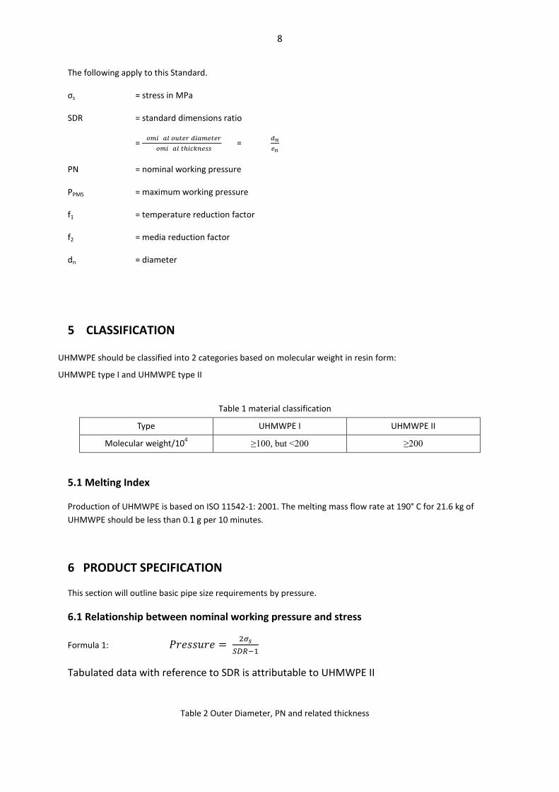
6.1 Relationship between nominal working pressure and stress
Formula 1:
Tabulated data with reference to SDR is attributable to UHMWPE II
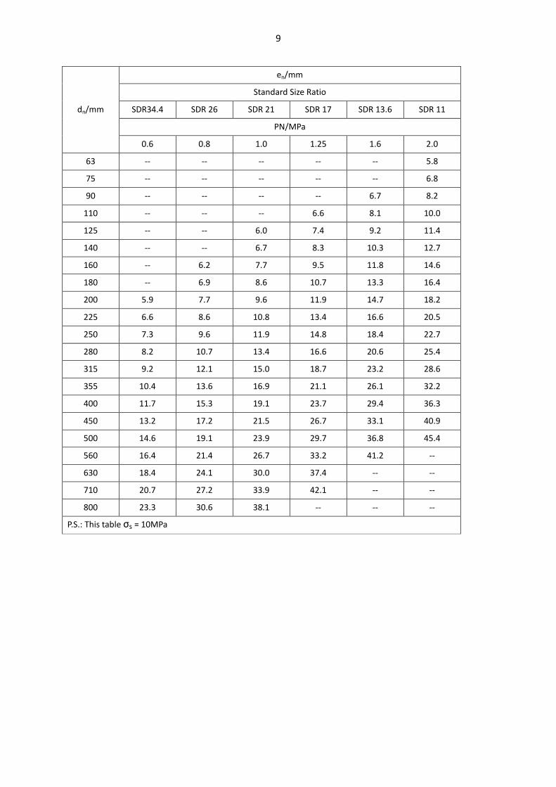
Table 2 Outer Diameter, PN and related thickness
9
dn/mm
en/mm
Standard Size Ratio
SDR34.4 SDR 26 SDR 21 SDR 17 SDR 13.6 SDR 11
PN/MPa
0.6 0.8 1.0 1.25 1.6 2.0
63 -- -- -- -- -- 5.8
75 -- -- -- -- -- 6.8
90 -- -- -- -- 6.7 8.2
110 -- -- -- 6.6 8.1 10.0
125 -- -- 6.0 7.4 9.2 11.4
140 -- -- 6.7 8.3 10.3 12.7
160 -- 6.2 7.7 9.5 11.8 14.6
180 -- 6.9 8.6 10.7 13.3 16.4
200 5.9 7.7 9.6 11.9 14.7 18.2
225 6.6 8.6 10.8 13.4 16.6 20.5
250 7.3 9.6 11.9 14.8 18.4 22.7
280 8.2 10.7 13.4 16.6 20.6 25.4
315 9.2 12.1 15.0 18.7 23.2 28.6
355 10.4 13.6 16.9 21.1 26.1 32.2
400 11.7 15.3 19.1 23.7 29.4 36.3
450 13.2 17.2 21.5 26.7 33.1 40.9
500 14.6 19.1 23.9 29.7 36.8 45.4
560 16.4 21.4 26.7 33.2 41.2 --
630 18.4 24.1 30.0 37.4 -- --
710 20.7 27.2 33.9 42.1 -- --
800 23.3 30.6 38.1 -- -- --
P.S.: This table σs = 10MPa
10
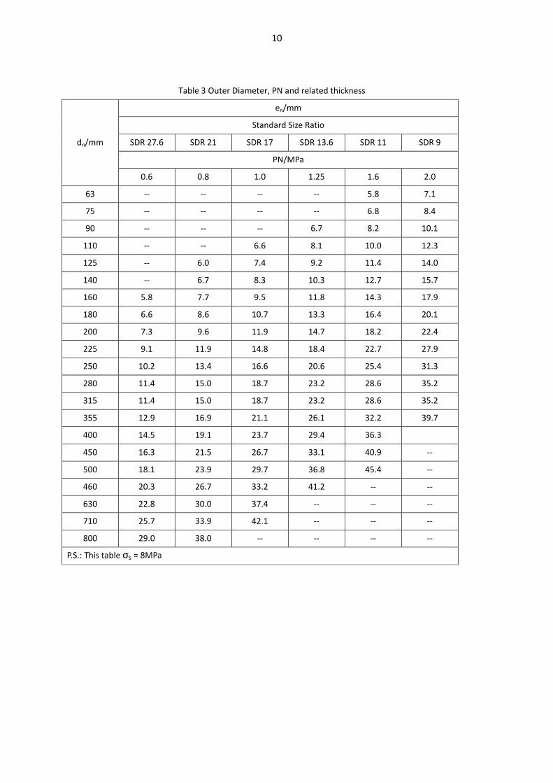
Table 3 Outer Diameter, PN and related thickness
dn/mm
en/mm
Standard Size Ratio
SDR 27.6 SDR 21 SDR 17 SDR 13.6 SDR 11 SDR 9
PN/MPa
0.6 0.8 1.0 1.25 1.6 2.0
63 -- -- -- -- 5.8 7.1
75 -- -- -- -- 6.8 8.4
90 -- -- -- 6.7 8.2 10.1
110 -- -- 6.6 8.1 10.0 12.3
125 -- 6.0 7.4 9.2 11.4 14.0
140 -- 6.7 8.3 10.3 12.7 15.7
160 5.8 7.7 9.5 11.8 14.3 17.9
180 6.6 8.6 10.7 13.3 16.4 20.1
200 7.3 9.6 11.9 14.7 18.2 22.4
225 9.1 11.9 14.8 18.4 22.7 27.9
250 10.2 13.4 16.6 20.6 25.4 31.3
280 11.4 15.0 18.7 23.2 28.6 35.2
315 11.4 15.0 18.7 23.2 28.6 35.2
355 12.9 16.9 21.1 26.1 32.2 39.7
400 14.5 19.1 23.7 29.4 36.3
450 16.3 21.5 26.7 33.1 40.9 --
500 18.1 23.9 29.7 36.8 45.4 --
460 20.3 26.7 33.2 41.2 -- --
630 22.8 30.0 37.4 -- -- --
710 25.7 33.9 42.1 -- -- --
800 29.0 38.0 -- -- -- --
P.S.: This table σs = 8MPa
11
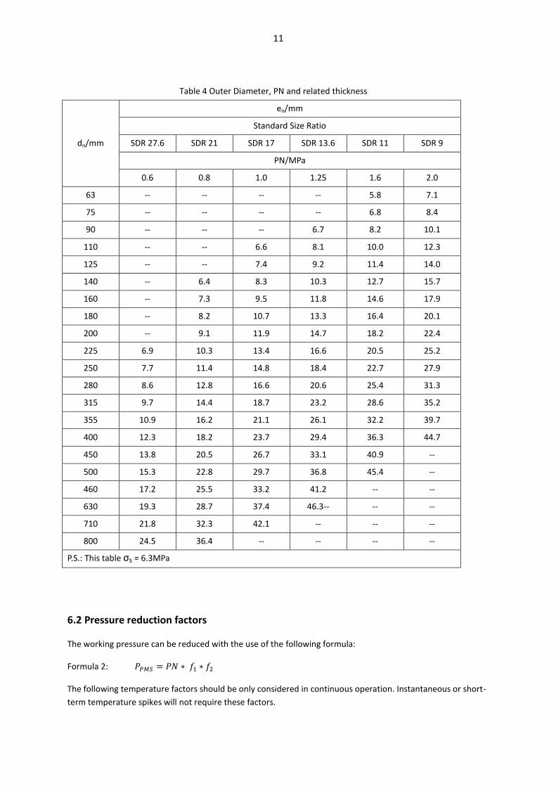
Table 4 Outer Diameter, PN and related thickness
dn/mm
en/mm
Standard Size Ratio
SDR 27.6 SDR 21 SDR 17 SDR 13.6 SDR 11 SDR 9
PN/MPa
0.6 0.8 1.0 1.25 1.6 2.0
63 -- -- -- -- 5.8 7.1
75 -- -- -- -- 6.8 8.4
90 -- -- -- 6.7 8.2 10.1
110 -- -- 6.6 8.1 10.0 12.3
125 -- -- 7.4 9.2 11.4 14.0
140 -- 6.4 8.3 10.3 12.7 15.7
160 -- 7.3 9.5 11.8 14.6 17.9
180 -- 8.2 10.7 13.3 16.4 20.1
200 -- 9.1 11.9 14.7 18.2 22.4
225 6.9 10.3 13.4 16.6 20.5 25.2
250 7.7 11.4 14.8 18.4 22.7 27.9
280 8.6 12.8 16.6 20.6 25.4 31.3
315 9.7 14.4 18.7 23.2 28.6 35.2
355 10.9 16.2 21.1 26.1 32.2 39.7
400 12.3 18.2 23.7 29.4 36.3 44.7
450 13.8 20.5 26.7 33.1 40.9 --
500 15.3 22.8 29.7 36.8 45.4 --
460 17.2 25.5 33.2 41.2 -- --
630 19.3 28.7 37.4 46.3-- -- --
710 21.8 32.3 42.1 -- -- --
800 24.5 36.4 -- -- -- --
P.S.: This table σs = 6.3MPa
6.2 Pressure reduction factors
The working pressure can be reduced with the use of the following formula:
Formula 2:
The following temperature factors should be only considered in continuous operation. Instantaneous or short-
term temperature spikes will not require these factors.
12
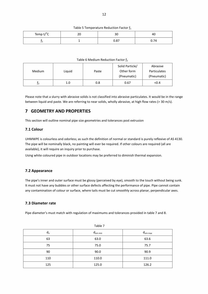
Table 5 Temperature Reduction Factor ƒ1
Temp t/oC 20 30 40
ƒ1 1 0.87 0.74
Table 6 Medium Reduction Factor ƒ2
Medium Liquid Paste
Solid Particle/
Other form
(Pneumatic)
Abrasive
Particulates
(Pneumatic)
ƒ2 1.0 0.8 0.67 <0.4
Please note that a slurry with abrasive solids is not classified into abrasive particulates. It would be in the range
between liquid and paste. We are referring to near solids, wholly abrasive, at high flow rates (> 30 m/s).
7 GEOMETRY AND PROPERTIES
This section will outline nominal pipe size geometries and tolerances post extrusion
7.1 Colour
UHMWPE is colourless and odorless; as such the definition of normal or standard is purely reflexive of AS 4130.
The pipe will be nominally black, no painting will ever be required. If other colours are required (all are
available), it will require an inquiry prior to purchase.
Using white coloured pipe in outdoor locations may be preferred to diminish thermal expansion.
7.2 Appearance
The pipe’s inner and outer surface must be glossy (perceived by eye), smooth to the touch without being sunk.
It must not have any bubbles or other surface defects affecting the performance of pipe. Pipe cannot contain
any contamination of colour or surface, where tails must be cut smoothly across planar, perpendicular axes.
7.3 Diameter rate
Pipe diameter’s must match with regulation of maximums and tolerances provided in table 7 and 8.
Table 7
dn dem min dem max
63 63.0 63.6
75 75.0 75.7
90 90.0 90.9
110 110.0 111.0
125 125.0 126.2

13
140 140.0 141.3
160 160.0 161.5
180 180.0 181.7
200 200.0 201.8
225 225.0 227.1
250 250.0 252.3
280 280.0 282.6
315 315.0 317.9
355 355.0 358.2
400 400.0 403.6
450 450.0 454.1
500 500.0 504.5
560 560.0 565.0
630 630.0 635.7
710 710.0 716.4
800 800.0 807.2
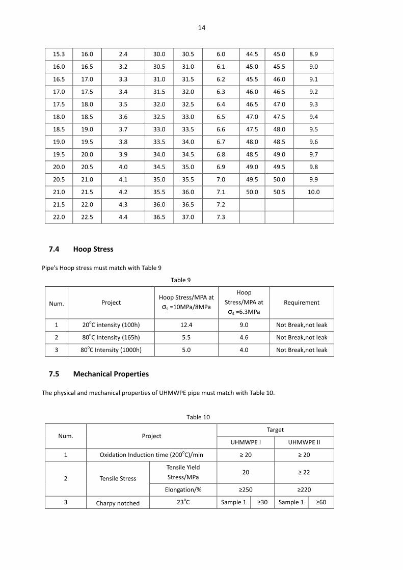
Table 8 Thickness Tolerance
ey min Tolerance
ty
ey min Tolerance
ty
ey min Tolerance
ty > ≤ > ≤ > ≤
5.3 6.0 0.9 22.5 23.0 4.5 37.0 37.5 7.4
6.0 6.6 1.0 23.0 23.5 4.6 37.5 38.0 7.5
6.6 7.3 1.1 23.5 24.0 4.7 38.0 38.5 7.6
7.3 8.0 1.2 24.0 24.5 4.8 38.5 39.0 7.7
8.0 8.6 1.3 24.5 25.0 4.9 39.0 39.5 7.8
8.6 9.3 1.4 25.0 25.5 5.0 39.5 40.0 7.9
9.3 10.0 1.5 25.5 26.0 5.1 40.0 40.5 8.0
10.0 10.6 1.6 26.0 26.5 5.2 40.5 41.0 8.1
10.6 11.3 1.7 26.5 27.0 5.3 41.0 41.5 8.2
11.3 12.0 1.8 27.0 27.5 5.4 41.5 42.0 8.3
12.0 12.6 1.9 27.5 28.0 5.5 42.0 42.5 8.4
12.6 13.3 2.0 28.0 28.5 5.6 42.5 43.0 8.5
13.3 14.0 2.1 28.5 29.0 5.7 43.0 43.5 8.6
14.0 14.6 2.2 29.0 29.5 5.8 43.5 44.0 8.7
14.6 15.3 2.3 29.5 30.0 5.9 44.0 44.5 8.8
14
15.3 16.0 2.4 30.0 30.5 6.0 44.5 45.0 8.9
16.0 16.5 3.2 30.5 31.0 6.1 45.0 45.5 9.0
16.5 17.0 3.3 31.0 31.5 6.2 45.5 46.0 9.1
17.0 17.5 3.4 31.5 32.0 6.3 46.0 46.5 9.2
17.5 18.0 3.5 32.0 32.5 6.4 46.5 47.0 9.3
18.0 18.5 3.6 32.5 33.0 6.5 47.0 47.5 9.4
18.5 19.0 3.7 33.0 33.5 6.6 47.5 48.0 9.5
19.0 19.5 3.8 33.5 34.0 6.7 48.0 48.5 9.6
19.5 20.0 3.9 34.0 34.5 6.8 48.5 49.0 9.7
20.0 20.5 4.0 34.5 35.0 6.9 49.0 49.5 9.8
20.5 21.0 4.1 35.0 35.5 7.0 49.5 50.0 9.9
21.0 21.5 4.2 35.5 36.0 7.1 50.0 50.5 10.0
21.5 22.0 4.3 36.0 36.5 7.2
22.0 22.5 4.4 36.5 37.0 7.3
7.4 Hoop Stress
Pipe's Hoop stress must match with Table 9
Table 9
Num. Project Hoop Stress/MPA at
σs =10MPa/8MPa
Hoop
Stress/MPA at
σs =6.3MPa
Requirement
1 20oC intensity (100h) 12.4 9.0 Not Break,not leak
2 80oC Intensity (165h) 5.5 4.6 Not Break,not leak
3 80oC Intensity (1000h) 5.0 4.0 Not Break,not leak
7.5 Mechanical Properties
The physical and mechanical properties of UHMWPE pipe must match with Table 10.
Table 10
Num. Project Target
UHMWPE I UHMWPE II
1 Oxidation Induction time (200oC)/min ≥ 20 ≥ 20
2 Tensile Stress
Tensile Yield
Stress/MPa 20 ≥ 22
Elongation/% ≥250 ≥220
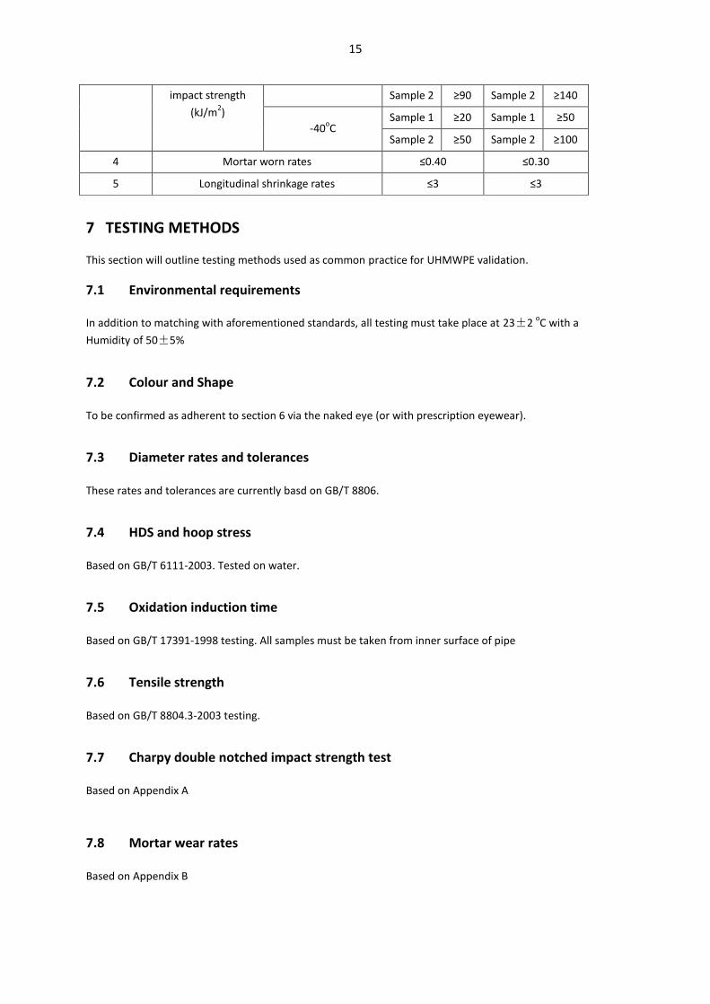
3 Charpy notched 23oC Sample 1 ≥30 Sample 1 ≥60
15
impact strength
(kJ/m2)
Sample 2 ≥90 Sample 2 ≥140
-40oC
Sample 1 ≥20 Sample 1 ≥50
Sample 2 ≥50 Sample 2 ≥100
4 Mortar worn rates ≤0.40 ≤0.30
5 Longitudinal shrinkage rates ≤3 ≤3
7 TESTING METHODS
This section will outline testing methods used as common practice for UHMWPE validation.
7.1 Environmental requirements
In addition to matching with aforementioned standards, all testing must take place at 23±2 oC with a
Humidity of 50±5%
7.2 Colour and Shape
To be confirmed as adherent to section 6 via the naked eye (or with prescription eyewear).
7.3 Diameter rates and tolerances
These rates and tolerances are currently basd on GB/T 8806.
7.4 HDS and hoop stress
Based on GB/T 6111-2003. Tested on water.
7.5 Oxidation induction time
Based on GB/T 17391-1998 testing. All samples must be taken from inner surface of pipe
7.6 Tensile strength
Based on GB/T 8804.3-2003 testing.
7.7 Charpy double notched impact strength test
Based on Appendix A
7.8 Mortar wear rates
Based on Appendix B
16
7.9 Oxidation induction time
Based on GB/T 17391-1998 testing. All samples must be taken from inner surface of pipe
7.5 Longitudinal shrinkage rates
Based on GB/T 6671-2001 testing. At revised temperature of is 110±2oC
8 TESTING REGULATIONS
All product must pass factory quality control and have certification guaranteeing such.
8.1 Batching and sampling
The total weight of each batch is to not exceed 50t. Further, if the production of said batch of UHMWPE
exceeds 30 days, it cannot be considered to be within the same batch as pipes manufacturer herewith.
Sampling is to be conducted based on GB/T 2828.1-2003 using the sampling plan Table 11
Table 11 Sampling plan
Batch Qty (N) Sample Qty (n) Acceptable Qty (Ac) Refuse Qty (Re)
<25 2 0 1
26~150 8 1 2
151~280 13 2 3
281~500 20 3 4
501~1200 32 5 6
1201~3200 50 7 8
3201~10.000 80 10 11
8.2 Factory inspection
Factory inspection is to include samples for hydrostatic testing, charpy testing and tensile yield testing as
previously indicated.
The grouping of these inspections are to be determined nominally through size by Table 12.
Table 12 size group and outer diameter of pipe
Group 1 2 3
Outer Diameter 63~225 >225~630 >630~800
9 MARKING AND STORAGE
9.1 Marking
All pipe should be marked with the following as a minimum:
17
---Name of firm/trademark (permanent mark);
---Name of product, type, size specification;
---Production date;
---PN;
---The number of standard.
9.2 Storage and transportation
Pipe must not be tossed when loading or unloading. Further, if using a forklift, it must be held from either end
and lifted at the centre. Forks may not be used down the length of pipe. Further, the pipe must not be
contaminated by any oil or chemical.
During storage, pipe must be kept away from heat and should be housed indoors away from UV exposure. Pipe
should not be stored at heights above 2m for the safety of personnel.
18
Appendix A
Charpy double notched impact strength testing method
A.1 Scope
This appendix it to show how to test UHMWPE pipes using Charpy double notched impact strength
testing method
A.2 Equipment
Notched impact strength testing device as dictated by GB/T 1043-1993 standard
A.3 Sampling
A.3.1 Sampling Shape
Sampling surface must smooth, without bubbles or cracks. Further, it cannot be stratified or appear
damaged in any way to the naked eye.
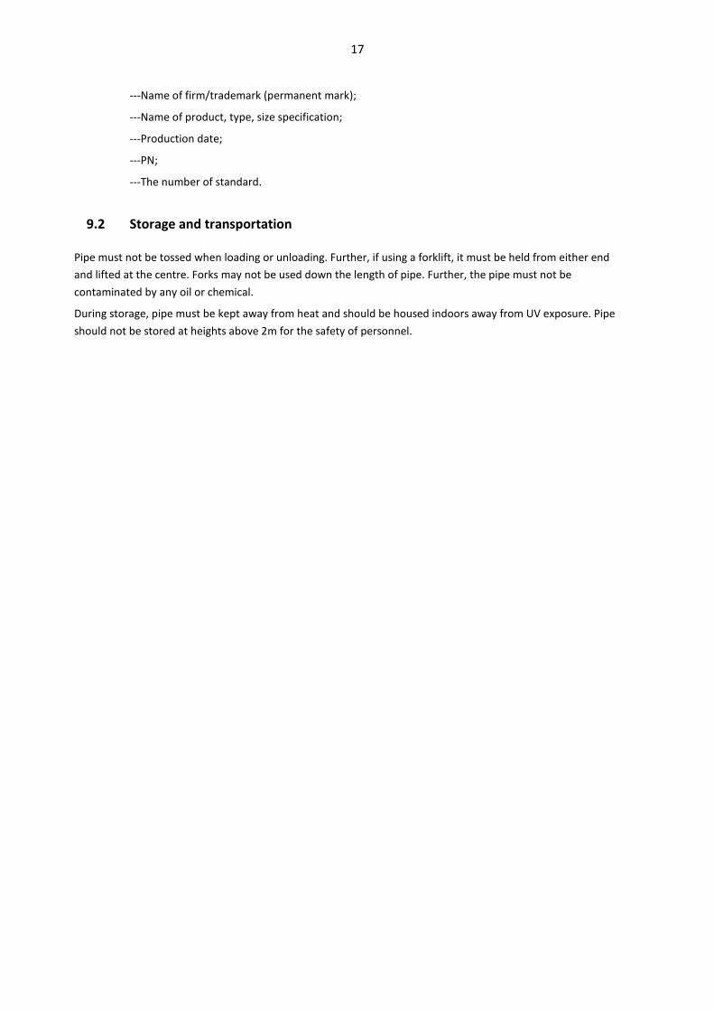
A.3.2 Sampling forms and size
Based on ISO 11542-2: 1998; please see picture A.1 for form and table A.1, 2 for notch depth requirements
Picture A.1 Sampling forms
Table A.1 Sampling type, size
Sampling
Type
Length (l) Width (b) Thickness (d) Space of
support Base size Tolerance Base size Tolerance Base size Tolerance
1 80 ±2 10 ±0.5 4 ±0.5 60
2 120 ±2 15 ±0.5 10 ±0.5 70
P.S.: wall thickness smaller than 12mm use the sampling type 1
Table A.2 Sampling notch depth
Sampling type 1 Sampling type 2
1 1.3±0.1
2 3±0.1
A.3.3 Sampling preparation
19
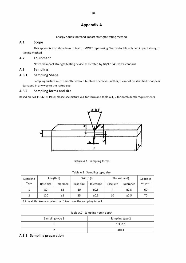
A.3.3.1 Example
The sample must be cut at parallel with the direction with pipe's main axis, see picture A.2.
Picture A.2 Sampling method
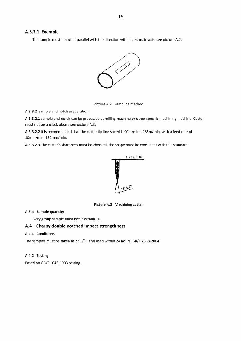
A.3.3.2 sample and notch preparation
A.3.3.2.1 sample and notch can be processed at milling machine or other specific machining machine. Cutter
must not be angled, please see picture A.3.
A.3.3.2.2 It is recommended that the cutter tip line speed is 90m/min - 185m/min, with a feed rate of
10mm/min~130mm/min.
A.3.3.2.3 The cutter’s sharpness must be checked, the shape must be consistent with this standard.
Picture A.3 Machining cutter
A.3.4 Sample quantity
Every group sample must not less than 10.
A.4 Charpy double notched impact strength test
A.4.1 Conditions
The samples must be taken at 23±2oC, and used within 24 hours. GB/T 2668-2004
A.4.2 Testing
Based on GB/T 1043-1993 testing.
20
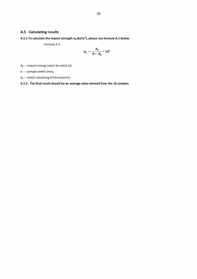
A.5 Calculating results
A.5.1 To calculate the impact strength αk (kJ/m2), please use formula A.1 below.
Formula A.1:
Ak----impact energy taken by notch (J);
b ----sample width (mm);
dk----notch remaining thickness(mm).
A.5.2 The final result should be an average value derived from the 10 samples
21
Appendix B
Mortar wear rates testing method
B.1 Scope
This appendix will provide a method for testing UHMWPE pipe mortar worn rates. A test which offers
objective results to UHMWPE’s supremacy against heavy wear.
B.2 Process
Place a sample of pipe into a vessel with particulates. Spin the sample for a pre-determined time. Check the
samples revised size and weight post duress. Comparison against original based on volume provides index.
B.3 Material and reagents
B.3.1 Quartz sand: SiO2≥99%; Fe2O3≤0.2%; heat resistance > 1600oC; granularity: 450μm - 900μm.
B.3.2 Particulates: combined from quartz sand and water with 3:2 scale
B.3.3 Acetone: analyzed alcohol.
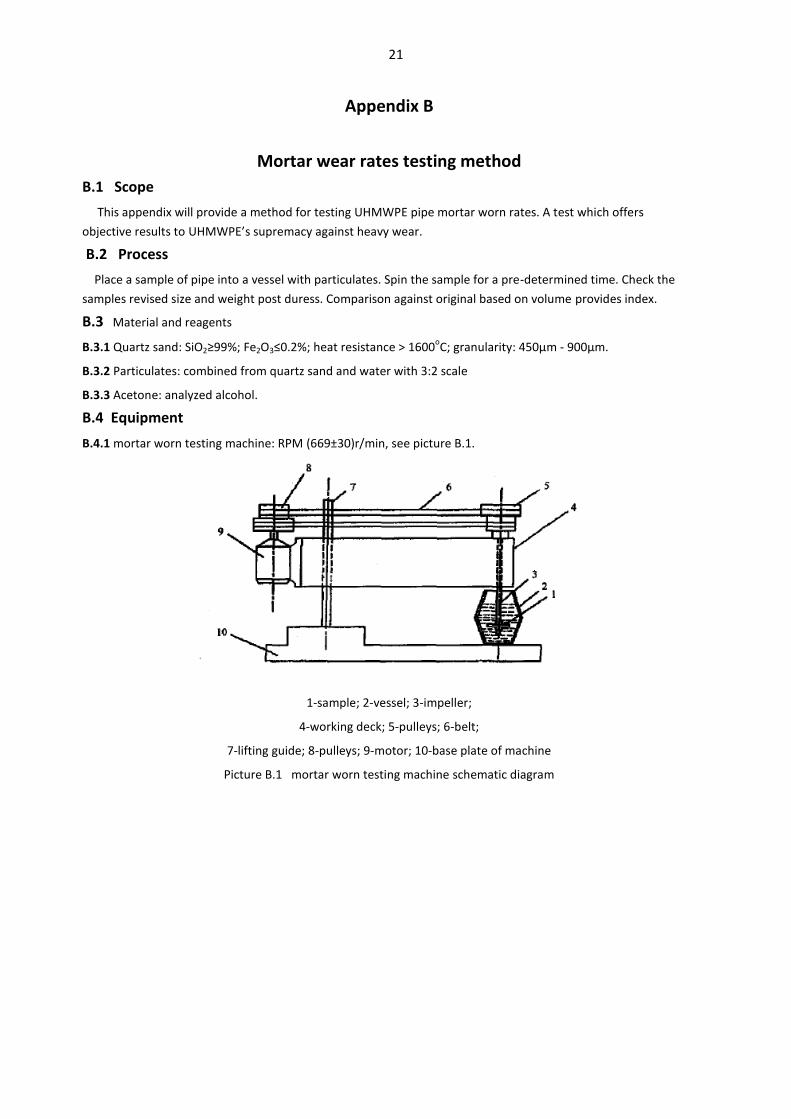
B.4 Equipment
B.4.1 mortar worn testing machine: RPM (669±30)r/min, see picture B.1.
1-sample; 2-vessel; 3-impeller;
4-working deck; 5-pulleys; 6-belt;
7-lifting guide; 8-pulleys; 9-motor; 10-base plate of machine
Picture B.1 mortar worn testing machine schematic diagram

22
B.4.2 Special clamps and mortar vessels, see picture B.2
Picture B.2 special clamps and center of mortar vessels schematic diagram
B.4.4 Scale: accurate to 0.1mg
B.4.5 Electric blast blower: 0oC - 300
oC.
B.4.6 Blower.
B.4.7 Ultrasonic cleaner
B5 Sampling preparation
B.5.1 Samples taken at a consistent size 76mm X 26mm X 7mm from pipe sections parallel to flow.
B.5.2 Polish the surface with sandpaper until very smooth
B.5.3 Use a minimum of 3 samples per test.
Picture B.3 Sample size
B.6 Method
B.6.1 Flush sample with pure water, using the ultrasonic cleaner wash for 20 min.
B.6.2 Immerse sample in acetone for 20 min.
B.6.3 After immersing sample, dry at 50 deg C for 1 hr.
B.6.4 Use scale to weigh sample before wearing
B.6.5 Put sample into clamps, as per picture B.2, for four hours.
B.6.6 Take out worn out sample, use ultrasonic cleaner wash 20min, then flush with pure water.
B.6.7 Then use acetone solution immerse 20 min.

23
B.6.8 After immersing dry using the blower ,at 50oC for 1h. Let the material cool to room temperature.
B.6.9 Weigh worn out sample quality, then calculate wear rate.
B.7 Test Result
Wear rates, as a percentage, are to be calculated via B.1:
Wear rates
m1----quality before worn out (mg);
m2----quality after worn out (mg).
The final rate is to be an average of the three samples used.


