Abstract Bmax offers industrial solutions based on Ultra High Power (UHP) technology and provides manufacturing solutions for Magnetic Pulse (MP) Forming, Welding and Crimping as well as Electro-Hydro-Forming (EHF) processes. The LS-DYNA® Emag solver version 1.7 used in the Eddy’s current approximation allows modelling different parts of the system like coils, workpieces and the dynamic interactions between them. This module is used as an advanced design tool to for example optimize the Lorentz forces generated in the workpiece. To achieve accurate numerical results, many comparisons have been done using Photon Doppler Velocimeter (PDV) measurements implemented in specific test beds. The described case is of a tube crushing. We will also show how LS-OPT® identification and sensitivity capabilities have been used for material identification using the Magnetic Pulse Forming process. The main objective is to characterize the material dynamic behaviour in the strain rate ranges generated by the Bmax processes (around 1000 to 10,000/s). To summarise the LS-DYNA and the LS-PrePost® capabilities greatly aide the engineering team to provide feasible industrial solutions from tool design to building predictive models to study the feasibility of a project. We can now respond faster to customer specifications, but also understand better the physical processes ultimately reducing design costs by limiting the number of physical testing. Keywords: Eddy’s current solver, HPP, MPC, MPF, MPW, Material Identification
1 Introduction Bmax’s technology is based on the high concentration of electrical energy used to deform metal at extremely high speeds. Bmax offers industrial solutions based on this Ultra High Power (UHP) technology and provides manufacturing solutions for Magnetic Pulse (MP) Forming, Welding and Crimping as well as Electro-Hydro-Forming (EHF) processes. The multiphysic aspect is common to all these processes. During the Magnetic Pulse process, a Lorentz force is generated by a transient induced current into the conductor material of the workpiece. In few microseconds, the conductor can reach a speed of several decades of meter per second and can behave in a non-linear plasticity, causing damage and sometimes failures. The main advantage of these high velocity impact technologies is an enlarging of the industrial application fields by the control of multiphysic processes. They take the advantages of the dynamics to generate high pressures and high strain rates that improve material properties.
This article is an overview of how the LS-DYNA Emag Solver is used in designing applications for Bmax’s different processes. A short presentation of the technology principles will be followed by some application examples. A section will be dedicated to the comparison between numerical results and experimental ones. Due to the mechanical, electromagnetic and sometimes thermal material properties having a significant influence on process behaviour, we will show the on-going work concerning material parameter identification by MPF using LS-OPT®.
2 Physics & principles
2.1 Physics
According to Maxwell’s equations, a transient current in a conductor generates a magnetic field. If such a field is applied onto another conductor, an induced current is created and the electrical charge moving through the previous magnetic field involves a Lorentz force. Our systems produce a fast electrical discharge which is released through a coil to produce a short but very strong Lorentz force onto a conductor workpiece. Numerically, to solve these dynamic & multiphysic issues, a strong coupling between the Emag solver of LS-DYNA and the explicit Mechanical solution is used. Optionally a thermal coupling can be considered to improve the resistivity calculation and to calculate the heat transfer effects during the process [3]. In the Eddy’s current approximation, Maxwell’s equations are solved using a Finite Element Method (FEM) for the solid conductors coupled with a Boundary Element Method (BEM) to consider the surrounding air or insulators without meshing [3]. Usually, only the final parts of the system are modelled (coil + workpiece + anvil). The loading is then either an output voltage generated from an equivalent RLC circuit or a current imposed onto the coil.
2.2 Principles
The machines are adapted for a large range of power outputs. A standard machine is made up of several components:
- Pulse Generator, - Connectors with an optional transformer, - Workstation including a coil and the final set-up.
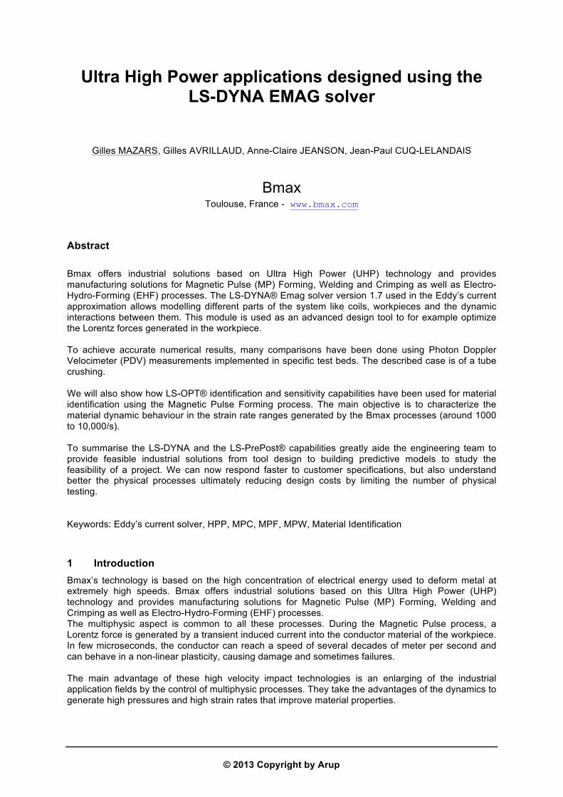
3 Experimental and numerical comparison This section shows work performed to validate the numerical models. The main objective was to -model the experimental set-up and to reproduce the dynamic velocity measurements. The set-up was made up of:
- A pulse generator: Charging voltage of 20kV max. - A power transformer 3:1 - A coil 80 mm in diameter - An aluminium 2024-T3 tube 77 mm in diameter
Figure 2 : General electrical circuit (left) and the functional part of the system with the coil (blue), the
tube (green) and the PDV (red arrow).
Rogowski coils are used to measure the current flowing into the primary and the secondary circuit of the transformer. A Photon Doppler Velocimeter (PDV) was implemented to estimate the crushing velocity of the internal diameter of the tube’s end. The Laser beam was guided by an optical fiber on an area 6 mm in diameter. The surface reflects the light which is captured by a photo detector. Electronics amplified the signal and provide a material velocity that depends on the laser frequency:
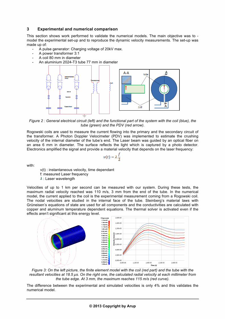
with: v(t) : instantaneous velocity, time dependant f: measured Laser frequency : Laser wavelength Velocities of up to 1 km per second can be measured with our system. During these tests, the maximum radial velocity reached was 110 m/s, 3 mm from the end of the tube. In the numerical model, the current applied to the coil is the experimental measurement coming from a Rogowski coil. The nodal velocities are studied in the internal face of the tube. Steinberg’s material laws with Grüneisen’s equations of state are used for all components and the conductivities are calculated with copper and aluminum temperature dependent equations. The thermal solver is activated even if the effects aren’t significant at this energy level.
Time (s) Figure 3: On the left picture, the finite element model with the coil (red part) and the tube with the
resultant velocities at 18.5 µs. On the right one, the calculated radial velocity at each millimeter from the tube edge. At 3 mm, the maximum reaches 115 m/s (red curve).
The difference between the experimental and simulated velocities is only 4% and this validates the numerical model.
4 Application examples High velocity impact technologies haves many more advantages and benefits than traditional methods. This section describes 3 different applications and their corresponding finite element models.
4.1 Magnetic Pulse Crimping (MPC)
Here, the images show an embedded joint generation between a tube and an anvil to close a pressurized chamber with specific requirements such as internal pressure (many hundreds of bars), tensile and/or torsion tests, water/liquid tightness, electrical insolation. The simulation also shows the electrical contact between 2 cylindrical components.
Figure 4 : (left) MPC 3D model, deformed shape (right) equivalent plastic strains in the tube and the anvil at the end of the process.
The LS-DYNA capabilities allow us to study the dynamic material behaviour, the impact conditions (velocities, angles…) and the efficiency of a coil design. For example, for cylindrical geometry, the coil presents a slot separating the input and output currents. In this region, the magnetic field is reduced and can involve heterogeneities in the crimping. The following simulation shows an aluminium-aluminium crimping where the dissymmetry of the crimping due to the slot effect of the coil has to be minimized to ensure required crimping quality.
Figure 5 : ¾ cutting view of the crimping set-up with the coil (red), the workpiece (tube in blue), the anvil (green) at 32 µs (left) and 59 µs (right). The white arrow shows the effect of a magnetic field
deficiency due to the slot.
The static failure strength has also been numerically evaluated by a pulling test that occurs later during the high speed forming phase.
When impact conditions are good in terms of angle and impact velocity, a plasma jet can be generated at the interface between the flyer and the anvil and can produce an intermetallic zone that results in a weld.
Figure 6: physical principle of MPW
The main advantages of this welding process are: - Sub-millisecond weld time - Dissimilar metals can be joined: eg. Aluminium/Magnesium, Stainless steel/copper,
Aluminium/copper… - High performance joining: stronger than Laser welding - Different shapes: flat, circular … - Solid-state cold weld, therefore no heat affected zone, no time lost on cooling
Figure 7: effective plastic strains obtained in the welding zone (left) and the MPW window (right)
The quality of the interface ensures a high performance weld regarding the mechanical stresses (pressure, tension, torsion…). Additionally, MPW can be successfully performed in the respect of highly severe specifications, like for example:
- Fatigue tests: the welding fatigue strength is more important than the jointed component ones. - 100% He Tightness : around of 10-7 or 10–8 mbar.L/s
LS-DYNA is used to define the welding windows for many dissimilar materials and to predict different welding conditions together using the experiment results .
• Similar to welding windows found in explosive welding • 2 main parameters : collision angle α and collision velocity Vc • Fine-tuning of the velocity mainly through the charging voltage • Radial impact velocity (Vr) ranging between 250 and 600 m/s.
Multiphysic couplings can show thermal effects, can estimate conductivity, shows areas where Joule’s effects are occurring (heating) and where the melting temperature is reached. In the following images, the shape of the coil shows a sharpe edge where the magnetic field was enhanced generating an increase of the current density that burned the coil (see picture).
Figure 8: The left picture shows the fringes of temperature obtained in the coil section (steel 40CMD8,
melting température is 1671°K, expected welding in red).The right picture presents the real melting zone after 15 shots.
The simulations reproduce this effect and highlight the damage zone in the section where the plastic strains are greater than 20%.
Figure 9: previous coil design with the damage zone.
Then a study was performed to reduce or delete these issues. With the 2D axisymmetric capability of the Emag solver, a new section has been suggested to the customer showing :
- a significant decreasing of the maximum temperature (several hundreds of degrees) - a plastic strain reduction factor of 10 (2% max) - a lower energy level is needed to produce the same welding in term of length and quality.
This application consists to push a workpiece (blank) in the bottom of a die. In function of the objectives, the coil can be generic (spiral) or specific. The dynamic material properties, the die geometry and others customer requirements are ones of parameters which define the coil design.
Figure 10: Example of deep drawing with a spiral coil, final shape (left) and Lorentz forces in the
workpiece (right)
In MPF, as there is no contact between the blank and the tools, except the die, it is easier to calculate the sliding considerations. The dynamic loading generates a high strain rate between 102 and 103/s during the process. A magnitude of 104/s can be reached during the impact of the workpiece onto the die. Finally, if the impact pressure is great enough, it can drastically reduce the neutral fiber springback when the impact velocity is correctly chosen. Another advantage of using this process is that the formability can be increased by more than 200% for certain aluminium grades. To study the feasibility of a project, usually LS-PREPOST Metal Forming capabilities (FLD, positioning, blank holder…) can be used. Another process called Indirect Magnetic Pulse Forming is Forming by high speed punch using an agent elastic material to form a blank and can be compared with traditional stamping. The impact velocity can reach several decades of meters per second. In this study below, the Emag solver is used to estimate the punch loading and the mechanical solution allows the study of the dynamic response of the elastomer and the interactions between the die and the blank.
Figure 11: principle (left) and example of flat engraving (right) of indirect MPF.
For example, a spiral coil can launch a heavy conductor punch. After the pulse, it has a resultant velocity, or kinetic energy. This energy is converted into internal energy in the elastomer. The hyper-elastic properties transform the loading and some of the initial kinetic energy from the punch to form or engrave the blank.
5 High speed material identification In the search to precisely define the dynamic behaviour of materials in UHP processes, an ongoing research project in the identification of high speed constitutive laws is being carried out. One of our test beds consists of an electromagnetic tube expansion set up where the radial velocity is measured by a PDV system. The coil current is measured by a Rogowski coil . The objective is to identify a set of parameters so as to reproduce the experiment results. The numerical model has been launched using the LS-DYNA version 980 v1.7 with the experimental current delivered to the coil.
Figure 12: 3D model used to optimized the real test bed (left) and 2D axisymmetric model for the
optimization and parameter identification with LS-OPT
2 models have been produced: the first one is a 3D model used for the design of an experimental set-up (coil size and material, current and energy levels…) and the second one, after validation, is using LS-OPT to perform the identification. One run is completed in 18 hours using 6 processors for the first 3D model and 15 minutes with 1 processor for the second one. For example, a modified Johnson-Cook material law can be chosen to model the tube material:
The parameters are to identify A, B, n and C. For this LS-OPT v4.2 is used. The thermal effects are ignored. The objective function is to minimize the RMS error between:
- The experimental radial velocities from PDV - The calculated radial velocity of a node on the outer diameter at the center of the tube. These
parameters are calculated by LS-OPT. To improve result accuracy, a multi-case parameter identification has been performed with several energy levels (or several tension levels). For each case, a RMS error is calculated and for each iteration, the function to minimize is the sum of the RMS error of each case [5]. The algorithm is a Hybrid Adaptive Simulated Annealing (ASA coupled with a gradient algorithm) and the sampling strategy is sequential without domain reduction to explore the whole design space. The optimization is stopped after 30 iterations with 8 runs for each iteration.
Figure 13: Comparison of radial velocities for an 1050 aluminum tube. The same set of parameters is used for 2 energy levels.
These methods allow the characterization of the materials’ plasticity, hardening, and strain rate dependences, experimentally, and provide us with recalibrated parameters in the LS-DYNA input file.
6 Conclusion Today, the reliability of Ultra High Power system components associated with powerful multiphysic design tools allow Bmax to offer industrial solutions for MP Forming, Electro-hydro Forming, MP Crimping and MP Welding. The LS-DYNA Emag capabilities are used:
- To build predictive models as required by Bmax customers - To respond faster to customers by predicting feasibility of projects - To design and optimize coils and set-up - To extrapolate experimental results & reduce design costs by limiting physical tests - To understand Physics
Electromagnetic couplings can be performed in a reasonable time scale and make possible iterative design with respect to industrial time and cost constraints.
7 Summary This article presents LS-DYNA capabilities and how they answer to Bmax needs in regards to its Ultra High Power processes involving dynamic and multiphysic features. Several examples of Magnetic Pulse simulations are presented showing LS-DYNA Emag solver as an advanced and effective design tool. A tube crushing study shows the excellent correlation between experimental and numerical results. Several other practical examples are shown as well as the dynamic characterization of materials using LS-OPT.
8 References [1] John O. Hallquist., LSTC. LS-DYNA® Keyword User’s Manual – Vol. I & II, version 971 R6.0.0,
February 2012. [2] John O. Hallquist. LS-DYNA® Theory Manual, March 2012. [3] L’Eplattenier, I. Caldichoury (LSTC). EM Theory Manual, Electromagnetism and Linear Algebra in
LS-DYNA, LS-‐DYNA v980 Revision Beta, LSTC-‐LS-‐DYNA-‐EM-‐THE-‐1.1-‐1, 14th November, 2011, P. [4] L’Eplattenier, I. Caldichoury (LSTC). Electromagnetism (EM) module User Manual in LS-‐DYNA 980,
11th May 2011, P. [5] Anne-‐Claire Jeanson (BMAX). Identification of High speed Law parameters using an
electromagnetic forming device. 25th January 2013, SLV/Bmax 2nd International Conference for Industrialized Magnetic Pulsed Welding & Forming, Munich/Germany
[6] G.R. Johnson and W.H. Cook. A constitutive model and data for metals subjected to large strains,
high strain rates and high temperatures. In Proceedings of the Seventh international symposium on ballistics, Hague, Netherlands, pages p. 541-‐547, 1983.
[6] W.H. Gourdin. Analysis and assessment of electromagnetic ring expansion as a high-‐strain-‐rate test.
Journal of Applied Physics, 65(2):411–422, 1989. M. Sedighi, M. Khandaei, and H. Shokrollahi. Identification of optimized constitutive model parameters at a high strain rate using electromagnetic ring expansion test results. Proceedings of the Institution of Mechanical Engineers PartC-‐Journal of Mechanical Engineering Science, 225(C4):781–789, Apr 2011.
[7] I. Henchi, P. L’eplattenier, G. Daehn, Y. Zhang, A. Vivek, N. Sander. Material constitutive parameter
identification using an electromagnetic ring expansion experiment coupled with LS-‐DYNA and LS-‐OPT, Proceedings of the 10th International LS-‐DYNA Users’ Conference, 2008.