SANDIA REPORT SAND97-2214 Ž UC-701 Unlimited Release Printed September 1997 Ultra-High-Speed Studies of Shock Phenomena in a Miniaturized System: A Preliminary Evaluation Wayne M. Trott, Kenneth L. Erickson Preparad by Sandia National Laboratories Albuquerque, New Mexico 87185 and Livermore, California 94550 Sandia is a multiprogram laboratory operated by Sandia Corporation, a Lockheed Martin Company, for the United States Department of Energy under Contract DE-AC04-94AL85000. Approved for public release; distribution is unlimited. Sandia National laboratories
Transcript
SANDIA REPORTSAND97-2214 Ž UC-701Unlimited ReleasePrinted September 1997
Ultra-High-Speed Studies of ShockPhenomena in a Miniaturized System:A Preliminary Evaluation
Wayne M. Trott, Kenneth L. Erickson
Preparad bySandia National LaboratoriesAlbuquerque, New Mexico 87185 and Livermore, California 94550
Sandia is a multiprogram laboratory operated by SandiaCorporation, a Lockheed Martin Company, for the United StatesDepartment of Energy under Contract DE-AC04-94AL85000.
Approved for public release; distribution is unlimited.
Sandia National laboratories
Issued by Sandia National Laboratories, operated for the United StatesDepartment of Energy by Sandia Corporation.NOTICE This report was prepared as an account of work sponsored by anagency of the United States Government. Neither the United States Govern-ment nor any agency thereof, nor any of their employees, nor any of theircontractors, subcontractors, or their employees, makes any warranty,express or implied, or assumes any legal liability or responsibility for theaccuracy, completeness, or usefulness of any information, apparatus, prod-uct, or process disclosed, or represents that its use would not infringe pri-vately owned rights. Reference herein to any specific commercial product,process, or service by trade name, trademark, manufacturer, or otherwise,does not necessarily constitute or imply its endorsement, recommendation,or favoring by the United States Government, any agency thereof, or any oftheir contractors or subcontractors. The views and opinions expressedherein do not necessarily state or reflect those of the United States Govern-ment, any agency thereof, or any of their contractors.
Printed in the United States of America. This report has been reproduceddirectly from the best available copy.
Available to DOE and DOE contractors fromOffice of Scientific and Technical InformationP.O. %X 62Oak Ridge, TN 37831
Prices available from (615) 576-8401, FTS 626-8401
Available to the public fromNational Technical Information ServiceU.S. Department of Commerce5285 port R.OytdRdSpringfield, VA 22161
ULTRA-HIGH-SPEED STUDIES OF SHOCK PHENOMENAIN A MINIATURIZED SYSTEM: A PRELIMINARY EVALUATION
Wayne M. Trott and Kenneth L. EricksonEnergetic and Multiphase Processes Department
Sandia National LaboratoriesP. O. Box 5800
Albuquerque, New Mexico 87185-0834
Abstract
A laboratory-scale experimental test system for small-scale studies of shock phe-nomena has been assembled. This system uses a variety of miniature test platformsin which shock loading is provided by laser-driven flyer impact. Acceptor materi-als include thin-film explosives and high-density metal foils. Optical access is pro-vided for high-speed optical diagnostics such as optically recording velocityinterferometry and single-pulse Ram an spectroscopy. The experimental assemblyfor Raman studies features a common laser source for both flyer generation andexcitation of Ram an scattering (to achieve high timing precision) and a detectionscheme that uses the coupling fiber for the excitation source to collect with highefficiency backscattered Raman light. Preliminary system evaluation experimentsindicate that detailed particle velocity studies of the dynamic material properties ofhigh-density metals under short-pulse, high-strain-rate loading can be performedin a miniaturized test configuration. Single-pulse Ram an studies on shock com-pressed thin film explosives also appear feasible if the thickness and grain struc-ture of these films can be tailored to enhance the Raman scattering signalsufficiently. Possible improvements in the experimental design and a number oflikely applications of these techniques are also discussed.
Acknowledgments
The excellent technical assistance of Jaime N. Castañeda is gratefully acknowledged. Flyertarget materials were skillfully prepared by Catharine Sifford of the Thin Film, Vacuum & Braz-ing Department 1471 at Sandia National Laboratories.
Preface
This work was supported by Laboratory Directed Research and Development (LDRD) fund-ing. The Appendix lists reporting information required by that finding source.
16. Graphical representation of aluminum flyer-lead shock interactions .......................................28
I. INTRODUCTION
Shocks produce an unusual realm of pressure and temperature, generated on a short timescale, that can induce a wide variety of physical and chemical changes in materials. Thesechanges (and their underlying processes) provide a very rich area of inquiry and potential discov-ery of ongoing relevance to many Sandia National Laboratories programs, including weaponcomponent design and evaluation, surety assessment, and advanced materials development. Thepursuit of predictive understanding in this field (as well as its associated applications) requires acontinuing investment in state-of-the-art experimental methods for real-time studies.
A viable experimental system for real-time examination of shock-induced physical and chem-ical changes in materials must combine techniques for well-controlled and well-characterizedshock loading with suitable high-speed diagnostic methods. To approach optimal shock loadingconditions, a large gas-gun driver is often used to generate high-speed plate impact in an analyti-cally tractable (e.g., planar) geometry. Multi-stage guns are required to achieve impact velocitiessubstantial] y greater than 2 km-s- ]. Studies involving complex test systems of this type are neces-sarily expensive and difficult to perform either rapidly or in large number. In general, thesedevices are not well suited to study shock-induced processes that occur with very short (i.e, nano-second) time scales. Moreover, these large-scale systems are impractical for investigation of rare,expensive, or highly toxic materials.
Several alternative methods for high-amplitude shock loading on a small scale have been con-sidered including electric exploding foil accelerators, 1a light-ion-beam driver for flyer plateacceleration,2 and direct irradiation of the target material with a high-intensity pulsed laser.3 Arecent approach adopted by several research groups involves radiation-induced shock generation
4-6Each of these methods offers advantages but is also subject to var-in a hohlraum configuration.ious significant limitations. For example, electric foil accelerators are unable to launch high-impedance metal flyers. In the direct laser irradiation technique, extensive tailoring of the lasertemporal and spatial profile is required to avoid the production of ill-conditioned shock waves.The light-ion-beam and radiation drivers involve expensive test systems that generally do not per-mit rapid “turn around.”
In this report, we describe preliminary efforts to develop, evaluate and use a unique, labora-tory-scale capability for detail ed examination of material response to well-controlled, short-dura-tion shocks. This system combines [1] well-characterized techniques for nearly planar shockcompression using laser-driven flyer plates, [2] thin-film or foil sample materials, and [3] high-speed, real-time optical diagnostics including optically recording velocity interferomet~ and sin-gle-pulse Raman spectroscopy. Experiments are performed with a variety of miniature test plat-forms that are designed for precisely timed optical access to the target material. In addition toproviding a safe and relatively inexpensive alternative to many experiments performed using gas-gun drivers, this capability is designed to allow previously inaccessible regimes of shock statesand chemical reactivity to be probed in detail. In particular, this concept represents a uniqueopportunity to study shock-induced thermomechanical and chemical processes that occur withextremely short (-1 -5 ns) character stic time scales--e. g., shock initiation of certain high explo-sives (such as fine-grain HNS and PETN) that can undergo transition to detonation under theseconditions.
This project was initiated with the support of LaboratoV Directed Research and Development(LDRD) finds received mid-year in FY96 and was assigned to the Phenomenological Modelingand Engineering Simulation Investment Area. In a review conducted a few months later, theInvestment Area Team decided that the project fell outside the defined scope of this group and itwas not recommended for continuation in FY97. Much of the short available time for this effortwas devoted to apparatus design and assembly. As a result the evaluation of the experimentalconcept summarized in this report is both preliminary and cursory; however, we include numer-ous recommendations for further exploration and application.
II. EXPERIMENTAL
A. Laser Drive Concept
The experimental system achieves nearly planar shock compression on a small scale (<l-mmdiameter) using laser-driven flyer plates. Laser-launched aluminum flyers can easily achieveimpact velocities exceeding 3 km-s-1, resulting in shock pressures of several hundred kilobars inmany materials. Shock durations, on the other hand, are only -10 ns or less. Enabling techniquesin this set-up include [1] the use of a laser source having a short coherence length (broad line-width), [2] multimode, step-index optical tapers and fibers to couple the high-intensity opticalradiation to the flyer target, and [3] composite flyer materials containing a thin, insulating barrier(e.g, A1203) to mitigate the deleterious effects of deep thermal diffusion. Properly configured, thelaser driver and optical transmission system can generate a uniform spatial intensity profile at thetarget plane, promoting very nearly planar launch conditions with precisely variable impact veloc-
7-9 A detailed description of the drive system components isities and accurate (-1 ns) timing .given below.
B. Miniature Test Platjorms
While the concept described in this report is applicable to a broad range of problems, we havefocused on the feasibility of examining shock compression states and rapid chemical reactions inenergetic materials. Test platforms designed for this task seek to achieve synergistic applicati on ofestablished techniques for thin-film energetic material preparation and high-speed optical diag-nostics in combination with laser-driven flyer impact. One platform consists of a miniature fixtureshown schematicallyy in Fig. 1. This assembly contains the output faces (separated by a knowndistance) of two optical fibers. One fiber face is coated with the flyer target material and the sec-ond face is coated with a thin-film (-1 Opm, appropriate to the time scale for well-characterizedshock loading) sample of energetic material. The flyer impact velocity is controlled by varyingthe laser fluence reaching the fiber output face, the flyer target thickness, and the thickness of thespacer that defines the “flight distance” of the impactor. The second fiber is used to carry the exci-tation source for single-pulse Raman spectroscopy as well as the backreflected Raman scatteringsignal from the shock compressed sample. This diagnostic provides a molecular level probe of theresponse of the parent species to shock loading and may also allow transient species and finalproducts of chemical reactions to be identified, if sufilcient sensitivity can be achieved. Miniatur-ized hardware (including polished optical fiber substrates for the energetic material thin films) forthis test platform was designed and fabricated.
Figure 2. Schematic diagram of miniature test platform for particle velocity measure-ments of the response of thin-film energetic materials using an optically recording velocityinterferometer system.
Complementary information about [1] the shock state of the unreacted energetic material or[2] global reaction progress (at sufficiently high shock pressure) can be obtained from high reso-lution particle velocity measurements. Figure 2 shows a schematic representation of a miniaturefixture prepared for comparison of thin film shock properties with the known response of bulkenergetic material. In tils design, the flyer impacts a window prepared with a very thin (-50 nm)coating of reflecting material (e.g., aluminum) and a “top” layer of the thin film energetic mate-rial. An optically recording velocity interferometer system (ORVIS)10is used to determine theresulting particle velocity history at the interface. Many available window materials such as fusedsilica, sapphire, LiF and BaF2 have been characterized for use in velocity interferometry. Opticalaccess must be provided for the focused beam of the interferometer source laser (an Ar+ continu-ous wave laser operated at 514.5 nm, -1 W single line) as well as for the light reflected from theinterface. The use of the very thin intermediate reflecting coating is a well-established techniquefor enhancing the reflected light signal without measurably perturbing the shock interaction at theinterface. For films prepared with densities, grain sizes, etc. that are equivalent to well-character-ized bulk material (see discussion on sample characterization in Section IIIA), the measured parti-cle velocities can be directly compared to the known bulk response. Tlis comparison allowschanges at the molecular level (obsemed with spectroscopic methods) to be correlated with theapplied shock pressure as a function of flyer impact velocity.
As the preceding discussion suggests, it would be desirable in many cases to tailor the ener-getic film deposition process to generate samples with properties closely matching interestingbulk materials (e.g., pressings of fine-particle HNS or PETN used in slapper initiation applica-tions). On the other hand, the thin film explosives obtained under different deposition conditionsmay prove to be very interesting materials as well. Recent innovations in line-imaging velocityinterferometry]I-13 may facilitate miniature scale equation-of-state measurements on theseuncharacterized samples. A test platform designed for this task (not fabricated in the presentwork) is shown in Fig. 3. The step profile on the window face is employed in preparing twoknown thicknesses of sample. Shock propagation through the stepped sample allows both shockvelocity and particle velocity to be measured with a line-imaging interferometer. A series of testswherein these two quantities are determined can be used in conjunction with the Rankine-Hugo-niot mass, momentum and energy jump conditions to derive a complete Hugoniot curve. In analternative approach, the thin film energetic material could be deposited over the flyer target foruse in “reverse impact” experiments on a regular interferometer window.
A different area addressed by this work involves the response of high-density metals to shockloading in a short-pulse, high-strain-rate (>107 s-l) regime. A fixture designed for these experi-ments is shown schematically in Fig. 4. The response of a metal foil either in contact with aninterferometer window or in a free surface configuration (as shown) can be examined in thissetup. Miniature hardware for fixtures of this type was designed and fabricated. In these experi-ments, ORVIS can be used for high-speed measurements of shock attenuation, “pull-back” veloc-ities of material going into tension, etc.
C. Sample Preparation
Flyer targets were prepared by physical vapor deposition on the output faces of 400-~ m-diameter,step-index, multimode optical fibers. The primary target material was aluminum; however, a
Spacer (Variable Thickness)
Thin-Film Eneraetic Material
Driving La gingInterferometry
(step profile on one face)
Figure 3. Schematic diagram of miniature test platform for equation of state measure-ments on thin-film energetic materials; simultaneous determination of shock velocity andparticle velocity using a line-imaging velocity interferometer.
~ Spacer (Variable Thickness)
w)r confined bywindow
Driving LaORVIS
Figure 4. Schematic diagram of miniature test platform for particle velocity measure-ments of the response of a high-density metal foil upon flyer impact.
0.25-pm layer of A1203 was embedded in the film (at a location near the fiber output face) toretard thermal diffision. This measure has proved to be somewhat effective in preventing heating,melting, etc. of the flyer material prior to impact.9
The thin film energetic material samples used in the present work were prepared by physicalvapor deposition, a technique that provides reasonably precise control of film properties. Thismethod can be used with any material that exerts sufficient vapor pressure (-1 O-5 -10-3 Torr) attemperatures low enough to ensure negligible decomposition. Films (primarily TA~) were pre-pared on three different substrate types: [1] polished output faces at one end of six-inch-long opti-cal fiber assemblies (for use in the test platform shown in Fig. 1); [2] 0.25-inch-diameter, 0.25-inch-thick optical windows (for use in the test platform shown in Fig. 2); and [3] thin sapphirediscs (4.75-mm-diameter, 0.5-mm-thick). The samples prepared on the thin sapphire pieces weregenerated as part of a characterization scheme (cf. Section IIIA). The a aratus and basic proce-
Pfdures for the vapor deposition process have been described previously. These procedures werefollowed with only minor modifications. In particular, special holders were fabricated to accom-modate the different substrates in the deposition chamber.
The metal foils used in the test platform shown in Fig. 4 were obtained from commercial sup-pliers. A 0.25-inch-diameter punch was used to prepare discs of the appropriate size for the testfixture. Prior to assembly, burrs were clipped from the edge of the disc and the foil was pressedbetween two smooth surfaces to remove all coarse wrinkles.
D. AsseinbL’yfor Single-Pulse Raman Spectroscopy
The experimental arrangement for single-pulse Raman spectroscopy studies is shown sche-matically in Fig. 5. To achieve the requisite timing precision for this application, it was desirableto have a common laser source for both flyer generation (the shock driver) and excitation ofRaman scattering (the optical probe of the shock loaded material). The available laser best suitedfor this task was a pulsed Nd:YAG laser (1.064 pm, -10-ns pulse duration) equipped with an in-line crystal for second harmonic generation at 532 nm. We used dichroic mirrors (labeled D1 andD2 in Fig. 5) to separate the frequency-doubled light from the unconverted fundamental radiation.This common source scheme ensures negligible “jittef’ between the infrared and visible compo-nents. Facile and reproducible control of delay times between these components can be achievedthrough straightforward changes of propagation length in the corresponding optical transmissionsystems (see discussion below).
The 1.064-pm radiation was directed to the point of application with the aid of a coaxiallyaligned, continuous wave HeNe laser (k = 632.8 rim). To align these sources, the Nd:YAG laserbeam path was first determined by taking “burn spots” (using photographic film or commercialbum paper) at two locations: [1] in the near field, just behind an alignment iris (cf. Fig. 5) and [2]in the far field (ahead of the focusing lens labeled FL2 in Fig. 5). After aligning the iris opening tothe bum record and then removing the bum paper or film, the HeNe laser was aligned to the irisopening and far-field bum spot via sequential adjustments of turning mirror, M2, and a secondmirror, KMl, located on a removable kinematic mount. Using the HeNe laser as a visible guide,the infrared beam was focused onto the input end of an optical fiber taper (Fiberguide Industries,Stirling, NJ) in which the core diameter reduction (from 1000 pm to 400 pm) is achieved over a
Figure 5. Schematic diagram of experimental arrangement for single-pulse Raman scattering studies. Num-bered labels denote dichroic mirrors (D), mirrors (M), mirror on removable kinematic mount (KM), filters (F),focusing lenses (FL), collimating lens (CL)
length of approximately 1 meter. The input face of the taper was positioned slightly past the focusof lens FL2 so that the diverging beam just “filled” the 1000-pm core diameter. This couplingmethod was used to minimize the intensity of “hot spots” in the beam at the first air/fiber interfaceand also to provide for some homogenization of the laser intensity ahead of the core diameterreduction to 400 pm. The laser energy reaching the output end of the taper was coupled across asmall air gap to the, input face of a 1-meter-long polished fiber assembly (C Technologies, Inc.,Cedar Knolls, NJ). The distal end of this assembly (coated with the flyer target material) wasinserted into the miniature test fixture as illustrated in Fig. 1. Absorption-type neutral density fil-ters (labeled F2 in Fig. 5) were used to adjust the laser output energy reaching the flyer target.
Active alignment of the frequency-doubled (532-rim) light was feasible with the Nd:YAGlaser operating at 30 Hz and at relatively low power. In a manner similar to that described above,this light was focused onto the input end (300-pm core diameter) of a variable length optical fiberdelay line. This component was designed to delay the Raman excitation source arrival time at theminiature test fixture (cf. Fig. 1) to compensate for the required flyer plate “flight time” across thegap distance defined by the spacer (-30-100 ns, depending on the flyer thickness, incident laserfluence, etc.). The optical propagation time delay, At, generated by this method is expressible interms of absolute physical quantities; i.e., At = bdc, where 1represents the fiber length, c is thefree-space velocity of light, and n is the refractive index of the material. For fused silica fiber, n =1.46071 at 532 nm. Hence, At= 4.87 ns per meter of fiber used in the delay line. Some consider-ation must also be given to the temporal dispersion in the fiber. The maximum delay time, td,oflight propagating along off-axis paths in the fiber compared to on-axis rays is given by
[)1 nco~——‘d = ;nCO
ncl
(1)
where 1and c are defined as before and nCOand ncl are the refractive indices of the fiber core and‘s For fiber with numerical aperture equal to 0.22 (as used in thecladding material, respectively.
present study), td = 56 ps/m. Since adequate delay times could be achieved with fiber lengthss 20meters, the timing uncertainty due to dispersion effects was -1 ns or less, a relatively minor fac-tor.
The temporally delayed 532-rim light exiting the fiber was collimated with a short focal lengthlens (labeled CL1 in Fig. 5) and transmitted through dichroic mirror D3. This light was focusedby lens FL3 onto the input end of a six-inch-long fiber optic assembly. The distal end of thisassembly (coated with the thin film energetic material) was installed in the test platform as shownin Fig. 1. Absorption-type neutral density filters (labeled F 1 in Fig. 5) were also used in this beampath to adjust the intensity of the Raman excitation source.
In this experimental design, the fiber used to transmit the Raman excitation source to the thinfilm energetic material also serves as an efficient collector of Raman scattered light from the sam-ple. This light exits the proximal face of the fiber optic assembly (in the direction opposite to thatof the incoming laser pul se) and is nearly collimated by lens FL3 (cf. Fig. 5). The Raman signal isseparated from backreflected and backscattered 532-rim light by reflecting it off the dichroic mir-ror (D3) and passing it through a 0.85-m double monochromator (Spex Model 1404). The dis-
persed spectrum is viewed by a silicon target vidicon coupled to a gateable proximity-focusedchannel intensifier tube (ITTiEOPD Model F4144), and the signal is processed by an optical mul-tichannel analyzer (OMA). The detector is gated on by a voltage pulse that is triggered ahead ofthe excitation source pulse by using appropriate digital delay generators. In the present work, a60-ns gate width was used to avoid any signal loss due to timing jitter and to provide some dis-crimination against background emission (e.g., long-lived sample fluorescence). This detectionsystem allows 4-rim increments of the sample Ram an spectrum to be viewed and recorded on asingle shot. The spectral resolution is typically 0.05 nm (-1.5 cm-1 at 570 rim). Wavelength cali-bration was accomplished by using the known line positions in the uranium emission spectrumgenerated by a hollow-cathode discharge tube. 16
Although the common source scheme used for both flyer generation and Raman excitationprovides advantages in experiment timing, it requires some compromise of system performance.Ideally, a narrow linewidth source is desirable for Raman excitation (to minimize instrumentalbroadening of the Raman transitions) while a broad linewidth (short coherence length) is advanta-geous in minimizing the modal noise propagating down the drive system fibers, thereby providinga more uniform intensity distribution at the fiber/flyer target interface and, hence, a more planarflyer launch. The Nd:YAG laser used in the present work has a relatively long coherence length.In fact, the measured linewidth of the frequency-doubled (532-rim) light is 1.5 cm-*, approxi-mately equal to the spectrometer resolution. At the effective resolution provided by this arrange-ment, most Raman transitions can be observed with negligible broadening, even at highdispersion. On the other hand, the comparably narrow linewidth of the fundamental (1 .064-pm)component may be expected to result in fairly severe fluctuations of the intensity distribution atthe fiber/flyer target interface. To address this issue, we examined the spatial profile of light exit-ing the distal end of an uncoated 1-meter-long fiber assembly by generating a magnified image ofthe output face at the detector plane of a solid-state array camera. Intensity distributions were ana-lyzed by a Multi cam 2.0 beam profiling system (Big Sky Software, Bozeman, MT). Profiles alonghorizontal and vertical lines (scaled to the fiber core diameter) intersecting the centroid of the spa-tial distribution are shown in Fig. 6. The overall distribution (from edge to edge) is fairly flathowever, numerous high-frequency peak-to-valley fluctuations of 2-4 times in intensity are seenacross the face of the fiber. At launch, these fluctuations may lead to nonplanar local segments inthe fl er geometry and may also encourage the formation and growth of Rayleigh-Taylor instabil-ities. 77 A detailed examination of the evolving flyer geomet~ as a fimct.ion of time is needed toaddress this concern.
We also obtained spatial profiles of the 532-rim light exiting the distal end of an uncoated fiberassembly. Typical horizontal and vertical line profiles are displayed in Fig. 7. Overall, the range ofobserved peak-to-valley fluctuations appears to be slightly less than that seen in the 1.064-pmlight used as the flyer plate driver, possibly reflecting some damping of the modal noise in thelong fiber delay line. A reasonably uniform Raman excitation source is useful in maximizing sig-nal while avoiding optically induced damage in the sample.
E. Assembly for Particle Velocity Measurements
The experimental arrangement for particle velocity tests is shown schematically in Fig. 8. Thedriving laser used in these experiments was an actively Q-switched Nd:Glass oscillator (Laser-
Horizontal Lineout
I00
100 200 3UU 400Distance (pm)
Vertical Lineout
100 200 300 400Distance (pm)
Figure 6. Spatial profile of the intensity of 1,064-pm light exiting a fiber assembly similar to that used for flyerlaunch. Horizontal and vertical line profiles intersecting the centroid of the spatial distribution are displayed.
-1
I I I
Horizontal Lineout
I I\
I
100 200 300 400—.Distance (pm)
1 I I
Vertical Lineou
o 1 t I
o 100 200 300 400Distance (pm)
Figure 7. Spatial profile of the intensity of 532-rim light exiting a fiber assembly used to transmit the Ramanexcitation source. Horizontal and vertical line profiles intersecting the centroid of the spatial distribution aredisplayed.
metrics Model 9380). Various diagnostics were used to determine important characteristics of thelight (k= 1.054 pm) entering and exiting the coupling fibers. Incident or transmitted laser energywas measured by a calibrated power-energy meter. The temporal profile of the laser was routine]ymonitored using an appropriate y filtered biplanar phototube coupled to fast oscilloscope (totaltime constant <0.4 ns). The laser output was horizontally polarized and multimode. Coarse spec-tral analysis indicated that the output was also relatively broadband (-1.3 rim). Under these condi-tions, the observed spatial profile at the exit face of an optical fiber should contain relatively smallintensity fluctuations due to modal noise propagation. This behavior was confirmed by measure-
9J18By adjusting the flashlampments on uncoated fibers using a beam profiling analysis system.bank voltage, the laser pulse duration could be varied over the range 16-50 ns (FWHM). All mea-surements in the present work were performed with pulse durations near 18 ns.
Techniques for aligning the infrared Nd:Glass laser beam to the visible HeNe laser and forcoupling laser energy into the optical fiber transmission system were essentially identical to thosedescribed in the previous section. The optical tapers and polished fiber optic assemblies wereobtained from commercial suppliers (Fiberguide Industries and C Technologies, Inc., respec-tively). The distal end of the fiber optic assembly (coated with the flyer target material) was onceagain installed in one side of the appropriate miniature test fixture (cf. Fig. 4). Absorption-typeneutral density filters (labeled F 1 in Fig. 8) were used to regulate the optical energy reaching theflyer targets.
ORVIS was used to determine both flyer performance and velocity-time histories for the flyer-impacted samples. Key elements of the interferometer system are shown in Fig. 9. A detaileddescription of the interferometer characteristics and operation is given in Ref. 10. Briefly summa-rized, particle velocity is linearly proportional to interferometer fringe displacement using thistechnique. In the present work, the fringe motion was viewed by an electronic image-converterstreak camera (Hadland Photonics, Ltd., IMACON 675) and recorded on an intensified CCDdetector. Digital image analysisl 9 was used to obtain accurate velocity-time records from theimage data.
III. PRELIMINARY RESULTS AND RECOMMENDATIONS
A. Thin Film Energetic Material Sample Characterization
Previous work*4 using optical and scanning electron microscopy (SEM), x-ray diffraction,and transmission electron microscopy has shown that vapor deposited energetic material thinfilms are well crystallized and relatively uniform. Some additional characterization of the density,porosity, grain size distributions, etc. of the thin films is required for interpretation of shock com-pression experiments. This information is particularly vital to any attempt to correlate theresponse of shock-loaded thin films with the known behavior of well-characterized bulk materi-als. To address this need, we developed a sample characterization strategy that involves the fol-lowing procedures: [1] film deposition on a low-mass substrate (i.e., the O.S-mm-thick sapphirediscs) to permit accurate measurement of the thin film mass using a microbalance with 0.1 pgsensitivity, [2] measurement of the flatness and uniformity of the thin film samples using an opti-cal, non-contact profilometer, and [3] determination of grain sizes and void distributions fromSEM images of sectioned samples. The microbalance and non-contact profilomet~ measure-
ments can be performed directly on the 0.25-inch-diameter, 0.25-inch-thick interferometer win-dows as well. Optical microscopy and non-contact profilometry can be used to compare samplesprepared on the polished fiber optic assemblies with those deposited on other substrates.
The TATB films prepared for this work were very uniform in appearance but somewhat thin-ner than expected (compared to previously observed deposition rates at a given temperature). Amagnified image (obtained from along-working-distance microscope) of a film prepared on oneof the 0.5-mm-thick sapphire discs is displayed in Fig. 10. From microbalance measurements, thefilm thickness in this case was determined to be -2 pm (assuming the theoretical maximum den-sity). Under a microscope at high magnification, the grain structure was barely observable (i.e.,very fine). The observed film properties were likely the result of the relatively low thermal massof the substrate holders. With this condition, the sample/substrate was probably maintained at asomewhat higher temperature than those encountered in previous deposition runs. *4A highertemperature undoubtedly promotes faster evaporation of the TATB, resulting in a relatively thindeposition; however, it should also lead to increased surface mobility, thereby generating a moreuniform sample. Time did not permit us to examine these films with the optical profiler or to sup-ply a sufficient quantity of sectioned films for SEM analysis.
Figure 10. Long-working-distance microscope image of TATB thin film deposited on thinsapphire disc. Dark vertical line corresponds to scribe mark made to assist the sectioningof the disc/sample. Bright “circle” in the center results tlom a small opening in the disc.Also seen are a few scratches produced by handling.
B. SingIe-Pulse Raman Spectroscopy System Evacuation
For initial evaluation of the Raman spectroscopy setup, we transmitted the 532-rim lightthrough the fiber delay line and coupled it into an uncoated, six-inch-long fiber optic assembly(cf. Fig. 5). Instead of installing the distal end of this assembly into the miniature test fixture, theoutput face was placed in close proximity to a pressed, granular pellet of a non-explosive sub-stance; ie., trans-stilbene. With this configuration, we were able to evaluate the collection effi-ciency of the fiber coupling scheme for Raman scattered light. Figure 11 displays a single-shotspectrum obtained using an excitation source energy of 1 mJ. The known20 ring stretching (581.4nm, 1594 cm-l) and C=C stretching (582.9 nm, 1639 cm-l) mode transitions in trans-stilbene areclearly seen. The required excitation source energy for this result is significantly lower than the 5-10 mJ typically employed in an earlier single-pulse Raman spectroscopy assembly.2 1’22The rela-tively efficient light collection efficiency in the present setup has the added benefit of minimizingthe possibility of optical]y induced damage in the sample. In fact, we observed no discoloration orevidence of ablation in the trans-stilbene material.
We were not successful in obtaining useful Ram an data from our initial run of TATB thinfilms deposited on the fiber optic assemblies. Visual inspection revealed that no optically induceddamage occurred at the excitation source intensities used. Moreover, it was readily apparent thatthese fine-grain films were largely transparent to visible light. The light trapping that occurs in aheterogeneous sample with relatively large grains evidently plays a large role in enhancing theRaman signal intensity. The negative result obtained in our initial tests suggests that this applica-tion requires substantially thicker films (-1 Opm or greater) with a coarser grain structure. Possi-ble techniques for production of these films include extended deposition times or, with somematerials, deposition from solution using either spin coating or an air brush applicator.
3,500
3,000
2,500
2,000
1,500
~ 1,000E& 500
0580 581 582 583
Wavelength (rim)
Figure 11. Single-pulse Raman spectrum from trans-stilbene. Fiber (400-pm diame-ter) used to transmit Raman excitation source and collect backscattered Raman signal.
C. Particle Velocity Measurements on High-Density A4etal Foils
Evaluation experiments involving flyer impact on tantalum foils (p = 16.65 g-cm-3) have beenperformed. These tests utilized the test platform configuration shown in Fig. 4 with velocity inter-ferometry measurements on the available free surface of the Ta acceptor. The flyers were gener-ated from a composite material containing a 0.25-pm-thick layer of A1203 embedded inaluminum. The total thickness of the composite material was 18 pm.
Figure 12 displays the velocity-time behavior of an 18-pm flyer for a particular drive condi-tion: 400-pm fiber core diameter, 30 mJ incident energy, 18 ns pulse duration. Also shown is thecalculated displacement vs. time. Repeated experiments at a fixed drive condition have demon-strated that shot-to-shot variations in flyer performance are quite small (2-3°/0or less). For a given“flight distance,” the expected impact conditions can be derived from the velocity and displace-ment curves. With a 0.003” (76.2 pm) separation between flyer target and acceptor, impact shouldoccur -60 ns after the onset of flyer motion. The predicted impact velocity is -1.7 km-s-l.
The redicted shock interaction can be obtained graphically using the known Hugoniot?cuwes2 for Al and Ta, as illustrated in Fig. 13. Impact of pure Al at the relatively modest velocity
of 1.7 km-s-1 should produce a high-amplitude (25 GPa) shock in the tantalum and introduce par-ticle motion at a velocity of-0.38 km-s-* in the acceptor. Approximately twice this velocityshould be recorded at the free surface.
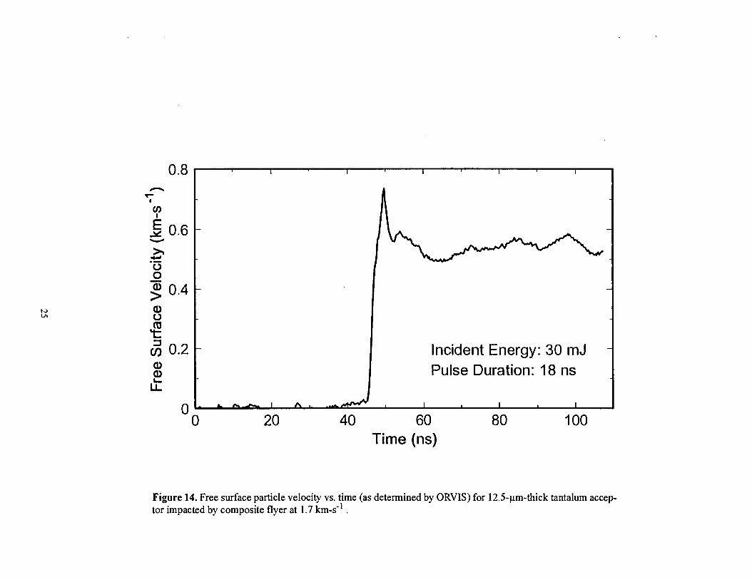
The results of an impact experiment on a 12.5-pm-thick foil of tantalum are shown in Fig. 14.The maximum particle velocity measured by ORVIS is consistent with the predicted shock inter-action. After the initial peak, a rapid “pull back” in the free surface velocity is observed. Thisbehavior corresponds to the characteristic signature of a material going into tension. Tensionstates in the material are created from the interaction of rarefaction waves emanating from the tar-get free surface and from the impactor. Wkh appropriate choices of impactor and acceptor thick-ness, the tension state geometry can be tailored to generate a span plane in the center of theacceptor. A series of experiments with an optimized geometxy can be used to investigate the spanstrength of the acceptor material. The preliminary data obtained here demonstrate that quantita-tive measurements of dynamic material properties can be obtained in a short-pulse, high-strain-rate regime and at the small scales of our miniature test platform. Straightforward improvementsare possible in the design of the impactor/acceptor geometty as well as in the temporal resolutionof the interferometer (determined by the optical delay incorporated in this device), recordingspeed, etc.
D. Recoinmendiztions for Future Work
Initial evaluation of the experimental concept summarized in this report indicates that high-speed diagnostics coupled with appropriate y designed small scale test platforms utilizing laser-driven flyer impact can be used to address a number of interesting problems in shock compressionscience. The preliminary results suggest several potential improvements in the experimentaldesign as well as additional areas of inquiry. In the single-pulse Raman spectroscopy application,a need for thicker energetic material films with coarser grain structure is readily apparent. Promis-
2 I I I I I
1.8 -.#
0“/“
/“=1.2 - /“* 0“.- 1 “; /’o 0.8 - /“>
.4“-
h 0.6 - .“* .“u 0.4 - /“ Incident Energy:30 mJ
0.2 - Pulse Duration: 18 ns
o [o 20 40 60 80 100
Time (ns)
140
120
20
0
Figure 12. Velocity-time behavior of 18-pm composite flyer as determined by ORVIS.Also shown is the calculated displacement vs. time curve.
Aluminum (mirror)
Flyer Velocity
at Impact
o 0.5 1 1.5 2Particle Velocity (km-s-’ )
Figure 13. Graphical representation of shock interaction resulting from aluminum flyerimpact (at 1.7 km-s-l) on a tantalum acceptor.
NVI
0.8n
u)
0.4
0.2a)a)
k
00
I I I I I
Incident Energy: 30 mJ
Pulse Duration: 18 ns
20 40 60
Time (ns)80 100
Figure 14. Free surface particle velocity vs. time (as determined by ORVIS) for 12.5-pm-thick tantalum accep-tor impacted by composite flyer at 1.7 km-s-1 .
ing approaches to this problem include extended deposition times or, for some materials, thedevelopment of suitable techniques for deposition from solution. The characterization strategyoutlined in Section IIIA needs to be fully implemented in order to define adequately the density,porosity, grain size distributions, etc. of the film samples. Considering the significant intensityfluctuations in the spatial profile of Nd:YAG laser light exiting a fiber, a reasonably completecharacterization of the dynamic behavior of flyers launched with this driver needs to be per-formed. If adequate flyer planarity can not be achieved with this system, an alternative driver/Raman excitation source needs to be developed. For investigation of high-density metals underthe short-pulse, high-strain-rate conditions of flyer impact, experiments should be performed withan optimized impactor/acceptor geome~ as well as with an optimized interferometer resolutionand recording rate.
Long-term uses or extensions of this experimental capability might include the following:[1] Short-duration shock compression studies of suitable TATBthin films using the single-
pulse Raman probe with comparison of results to theknown21’22 response of bulkTATB under sustained shock loading--a plot showing the behavior of two Raman tran-sitions under these conditions is reproduced in Fig. 15;
[2] Refinement of thin-film energetic material deposition processes to generate film densi-ties and porosities that match properties of currently used bulk explosives as closely aspossible--in particular, fine-grain formulations of explosives such as PETN or HNSthat can undergo transition to detonation with extremely short time scales;
[3] Detailed tests of the response of PETN and HNS thin films to short-pulse shock load-ing (to promote and assist development of models of the initiation and transition-to-detonation behavior of these materials under these conditions)--high-speed velocityinterferometry could be used to probe the equation of state of the unreacted explosiveat previously inaccessible shock conditions and to measure time-to-reaction in thenanosecond regime; additional fundamental physical and chemical information mightbe obtained using the Raman probe;
[4] Evaluation of the response of energetic material thin films exhibiting significantly dif-ferent morphologies than those occurring in bulk materials;
[5] Evaluation of strategies to extend the maximum available velocity of laser-generatedflyers (presently -4 km-s-l) to the hypervelocity regime (>7 km-s-l); factors contribut-ing to flyer “failure” at elevated drive conditions include rapid diffision of heat fromthe hot, driving plasma (leading to flyer melt and vaporization) and rapidly developingRayleigh-Taylor instabilities--possible approaches to achieve acceptable mechanicalintegrity and higher velocities include the use of different composite flyer target mate-rials and flyer generation with a broadband laser driver (to minimize instabilitiesdriven by variations in the laser intensity at the fiber/flyer interface); as illustrated inFig. 16, an extended velocity range would enable impact studies on high-density mate-rials (such as lead) at shock pressures well in excess of 100 GPa;
[6] Detailed measurements of the dynamic material properties of a high-density metal foil(e.g., Ta or Pb) at high-strain-rate (>107 S-l) conditions using ORVIS; results from afull test series would provide an important test for existing equation-of-state anddynamic material models in the short-pulse, high-strain-rate regime.
I 140
J 71.[
L160 1[80 200
RAMAN SHIFT (cm-i)
Figure 15. Response of two Rarnan transitions in TATB to sustained shock loading gener-ated by a gas-gun driver (reproduced from Ref. 22)
I
,“1“
,,“##
##“,,“
I,“
I
,“I
,“I
,“I
,“I
,“I
,“I
a“I
,“I
,“I
,’I
\.“
I
t“f
,“)
,“,“
)“,“
.“.“
/,c~
iii;iii.I”
t-,
.“
,
,,“
ns-
,“,
,“C
fJ.“
.“E
.“xinL
r5
/‘N/“
/...
I_,,.
.../y
/...
/
~./i’
-a-
-.:”
//
/
/r-
~“L.
,a’.
a’:-.I
II
-.I
1t
1I
..I
II
1
00
00
0m
%m
o0
mo
1
00
u)
CQ
mn
Y-1(f)
Exz*>
CD
0
IV. CLOSURE
We have assembled a laboratory-scale experimental test system for shock compression studiesutilizing a variety of miniature test platforms. The experimental capability combines [1] well-characterized techniques for short-duration, nearly planar shock compression using laser-drivenflyer impactors, [2] thin-film or foil sample materials, and [3] high-speed optical diagnostics suchas ORVIS and single-pulse Raman spectroscopy. Notable features of the experimental assemblydeveloped for Raman studies include a common source for both flyer generation and excitation ofRaman scattering (to achieve high timing precision via optical delays only) and a detectionscheme that uses the coupling fiber for the excitation source to collect backscattered Raman light.Single-pulse Raman spectra with high signal-to-noise at high dispersion were obtained from apressed, granular material at excitation source energies< 1 mJ (sufficiently low to avoid opticallyinduced damage in the sample). This result represents a significant improvement in collectionefficiency compared to a previous]y developed single-pulse Raman spectroscopy system. Ramanstudies on shock loaded energetic material thin films appear feasible if the thickness and grainstructure in these films can be tailored to increase the Raman scattering signal sufficiently. Pre-liminary particle velocity measurements of flyer impact on a high-density metal (e.g., Ta) accep-tor indicate that detailed studies of dynamic material properties under short-pulse, high-strain-rateloading can be peritormed in a miniaturized system. Finally, we have identified several areas forimprovement in the experimental design and suggested a number of interesting research problemsthat could benefit from this capability.
REFERENCES
1. R. Lee, J. Osher, H. Chau, M. Gerassimenko, G. Pomykal and R. Speer, M. J Impact Erzgng.14,451(1993).
2. H. Bachrnann, K. Baumung, G. I. Kanel, H. U. Karow, V. LichL D. Rusch, J. Singer and O. Stoltz, “Tar-get Experiments with Light-Ion Beams at KALIF,” 9th International Conference on High-Power Parti-cle Beams, Paper #PB-43, Washington, DC, May 1992.
3. S. Eliezer, I. Gilath, and T. Bar-Noy, J. Appl. I’hys. 67,715 (1990).4. B. Faral, M. Koenig, J. M. Boudenne, D. Batani, A. Benuzzi, S. Bossi, M. Temporal, S. Atzeni,
Th. Lower, “EOS Impedance Matching Experiments at High Pressure with Smoothed Laser Beam,” inShock Compression of CondensedMatter--l 995, S. C. Schmidtand W. C. Tao,eds., AIP Press,NewYork, 1996, pp. 943-946.
5. S. D. Rothman, A. M. Evans and N. J. Freeman, “Copper Shock Hugoniot Experiments Using HighPower Lasers,” in Shock Compression of CondensedMatter--l995, S. C. Schmidt and W. C. Tao, eds.,AIP Press, New York, 1996, pp. 77-80.
6. C. H. Konrad,W.M. Trott, C. A. Hall, J. S. Lash, R J. Dukart, D. L. HansoQ R. E. Olson,G. A. Chandler, K. J. Fleming, L. C. Chhabildas, T. G. Trucano and J. R. Asay, “Use of Z-Pinch Sourcesfor High-Pressure Shock Wave Experiments, “in Shock Compression of Condensed Matter--1997, S. C.Schmidt, D. P. Dandekar and J. W. Forbes, eds. (to be published).
7. R J. Lawrence and W. M. Trott, Int. J. Impact Engng. 14,439 (1993).8. W. M. Trott, “Studies of Laser-Driven Flyer Acceleration Using Optical Fiber Coupling,” in Shock
Compression of CondensedMatter--I 99l, S. C. Schmid$ R. D. Dick, J. W. Forbes and D. G. Tasker,eds., Elsevier, New York, 1992, pp. 829-832.
9. W. M. Trot$ “Investigation of the Dynamic Behavior of Laser-Driven Flyers,” in High-Pressure Scienceand Technology--I993, S. C. Schmidt, J. W. Shaner, G. A. Samara and M. Ross, eds., AIP Press, NewYork, 1994, pp. 1655-1658.
10. D. D. Bloomquist and S. A. Sheffie14 J. Appl. Phys. 54, 1717 (1983).11. W. F. Hemsing,A. R. Mathews, R. H. Warnes, and G. R Whittemore, “VISAR: Line-imaging Interfer-
ometer,” in SPIE Proceedings No. 1346, San Diego, CA, 1990, pp. 133-140.12. K. Baumung, J. Singer, S. V. Razorenov, and A. V. Utkin, “Hydrodynamic Proton Beam-Target Interac-
tion Experiments Using an Improved Line-imaging Velocimeter,” in Shock Compression of CondensedMatter–1995, S. C. Schmidtand W.C. Tao, eds., AIP Press,New York, 1996,pp. 1015-1018.
13. W. M. Trott and J. R. Asay, “Investigation of Microscale Shock Phenomena Using a Line-imagingOptically Recording Velocity Interferometer System,” “m Shock Compression of Condensed Matter–1997, S. C. Schmidt, D. P. Dandekar and J. W. Forbes, eds. (to be published).
14. K. L. Erickson, R. D. Skocypec, W. M. Trott and A. M. Renlund, “Development of Thin-Film Samplesfor Examining Condensed-Phase Chemical Mechanisms Affecting Combustion of Energetic Materials,in Proceedings of the 15th International Pyrotechnics Seminar, hosted by IIT Research Institute,Boulder, CO, 1990, pp. 239-260.
15. A. W. Snyder and J. D. Love, Optical Wmeguide Theory, Chapmanand Hall,New York, 1983,pp. 51-62.
16.B.A. Palmer,R. A. Keller, and R. Engleman, Jr., An Atlas of Uranium Emission Intensities in a HollowCathode Discharge, Los Alamos National Laboratory Report; LA-825 l-MS, July 1980.
17. A. M. Frank and W. M. TroK “Investigation of Thin Laser-Driven Flyer Plates Using Streak Imagingand Stop Motion Microphotography,” in Shock Compression of CondensedMatter--l 995, S. C.Schmidt and W. C. Tao, eds., AIP Press, New York, 1996, pp. 1209-1212.
18. W. M. Trott and K. D. Meeks, J. Appl. Phys. 67,3297 (1990).19. G. A. Fisk, G. A. Mastin and S. A. Sheffield, J. AppL Phys. 60,2266 (1986).20. Z. Meic and H. Gusten, Spectrochimica Acts 34A, 101 (1978).
21. W. M. Trott and A. M. Renlund, J. Phys. Chem. 92,5921 (1988).22. W. M. Trott and A. M. Renlund, “Pulsed-Laser-Excited Raman Spectra of Shock-Compressed Triami-
notrinitrobenzene,” in Proc. Ninth Symposium (i%temationa~ on Detonation, Portland, OR, 1989,pp. 153-161.
23. S. P. Marsh, cd., LASL Shock Hugoniot Data, U. CaliforniaPress, Berkeley,CA, 1980.
APPENDIX
Required Reportable InformationLaboratory Directed Research and Development
FY96 Mid-year LDRD Project: Ultra-High-Speed Studies of Shock Phenomena in aMiniaturized System