Page 1
1
Abstract — A novel dual-polarized patch antenna for
ultra-wideband (UWB) applications is presented. The antenna
consists of a square patch and four capacitively coupled feeds
to enhance the impedance bandwidth . Each feed is formed by a
vertical isosceles trapezoidal patch and a horizontal isosceles
triangular patch. The four feeds are connected to the
microstrip lines that are printed on the bottom layer of the
grounded FR4 substrate. Two tapered baluns are utilized to
excite the antenna to achieve high isolation between the ports
and reduce the cross-polarization levels. In order to increase
the antenna gain and reduce the backward radiation , a
compact surface mounted cavity is integrated with the
antenna. The antenna prototype has achieved an impedance
bandwidth of 112% at (|S11| ≤ -10 dB) whereas the coupling
between the two ports is below -28 dB across the operating
frequency range. The measured antenna gain varies from 3.91
to 10.2 dBi for port 1 and from 3.38 to 9.21 dBi for port 2, with
a 3-dB gain bandwidth of 107%.
Index Terms — UWB antenna, dual-polarized antenna,
patch antenna, capacitively coupled feed, surface mounted
cavity
I. INTRODUCTION
WB communication system has attracted increasing
attention due to its advantages of high speed data rate
and low spectral power density, since the Federal
Communications Commission (FCC) first approved the
frequency range from 3.1 to 10.6 GHz for commercial UWB
applications in 2002 [1]. This has increased the demands on
the UWB systems and subsequently to stimulate the
research activities in various UWB antenna designs [2-3].
Moreover, dual-polarized UWB antennas are more attractive
compared with linearly polarized antennas, as the channel
capacity is significantly enhanced due to the polarization
F. Zhu and S. Gao are with the School of Engineering and Digital Arts,
University of Kent, CT2 7NZ, UK. ([email protected] ;
[email protected] ).
A. TS Ho is with the Department of Computing, University of Surrey,
Guildford, GU2 7XH, UK ([email protected] ).
R. A. Abd-Alhameed is with Antennas and Applied Electromagnetics
Research Group, University of Bradford, Bradford, BD7 1DP, UK
([email protected] ).
C. H. See is with the Engineering, Sports, and Sciences (ESS) Academic
Group, University of Bolton, BL3 5AB, UK. ([email protected] )
T. W. C. Brown is with Centre for Communication Systems Research,
University of Surrey, Guildford, GU2 7XH, UK (T. [email protected] )
J. Z. Li, G. Wei and J. D. Xu are with Northwestern Polytechnical
University, Xi’an, 710072, P.R. China.
diversity technique. The performance of imaging/radar
systems can also be improved by employing dual-polarized
UWB antennas [4-5]. Challenges of dual-polarized UWB
antenna designs include wide impedance matching, high
isolation between two polarization ports, low
cross-polarization, stable radiation performance across the
wide bandwidth, and low-cost.
Microstrip patch antennas have been widely applied in
wireless communication systems mainly owing to their
characteristics of low-profile, low-cost and easy fabrication.
However, a single-layer patch antenna usually operates over
a limited frequency range only which can’t satisfy the
bandwidth requirements for UWB applications.
Consequently, several techniques have been proposed in
the literature to extend the bandwidth of dual-polarized
patch antennas. For example, one typical technique is the
use of various probe-fed mechanisms, such as printed
Γ-shaped probe [6], L-shaped probe [7-8], meandered-line
probe [9] and hook-shaped probe [10]. Another approach is
to employ stacked patches with capacitive-probe feed [11],
proximity feed [12] and aperture-coupled feed [13-17].
Alternatively, the bandwidth can be increased by
embedding slots in the patch [18-20]. Other techniques
include the hybrid feed technique such as L-shaped probe &
aperture-coupled feed [21], gap-coupled feed &
aperture-coupled feed [22], and meandered strip &
aperture-coupled feed [23], and employing
electromagnetic-fed method [24]. Recently, broadband
dual-polarized magneto-electric dipole antennas with
differential-feed have been proposed in [25-26].
Initially, compared with probe-fed patch antennas [6-12],
aperture-coupled stacked-patch antennas [13-17] can be
easily integrated with active RF circuits and to achieve high
polarization purity but high backward radiation. To increase
the front-to-back ratio and reduce the backward radiation, a
reflector patch can be employed below the feed to enhance
the desired performance [15-17]. Hybrid feed patch antennas
can achieve high isolation and low cross-polarization while
two ports may have different radiation characteristics. In
contrast to hybrid feed method, differential-feed technique
has been utilized in dual-polarized patch antennas as it can
enhance the port isolation and reduce cross -polarization
levels as shown in [7-8, 10, 19-20, 25-26]. To summarize and
compare some of the state-of-the-art work in wideband
Fuguo Zhu, Steven Gao, Member, IEEE , Anthony TS Ho, Senior Member, IEEE, Raed A. Abd-Alhameed, Senior
Member, IEEE, Chan H. See, Tim WC Brown, Member, IEEE, Jianzhou Li, Gao Wei, and Jiadong Xu
Ultra-Wideband Dual-Polarized Patch Antenna with
Four Capacitively Coupled Feeds
U
Page 2
2
dual-polarized patch antenna designs, Table 1 lists the
performances in terms of operational bandwidth (BW) and
port isolation among the previously mentioned designs. As
can be observed in Table 1, a few dual-polarized patch
antennas can achieve over 50% bandwidth [16, 25-26] but
they are unable to cover the whole UWB band (3.1-10.6 GHz).
Thus, the objective of this work is to design a low-cost
dual-polarized patch antenna which can operate over
3.1-10.6 GHz with high isolation, low cross-polarization
levels and stable radiation patterns.
Table 1 Performance of different dual-polarized patch antennas.
Ref. BW
(%)
Isolatio
n (dB) Ref.
BW
(%)
Isolatio
n (dB) Ref.
BW
(%)
Isolatio
n (dB)
[6] 24.9 29 [13] 20.9 36 [20] 31 35
[7] 23.8 30 [14] 24.4 30 [21] 27 25
[8] 29 30 [15] 39 35 [22] 14 40
[9] 26 25 [16] 52 39 [23] 14 40
[10] 37 40 [17] 33 16 [24] 38.7 40
[11] 30 NaN [18] 19 28 [25] 65.9 36
[12] 17 15 [19] 46.5 38 [26] 68 36
In this paper, a dual-polarized patch antenna capacitively
coupled through four feeds is proposed. Compared with
other dual-polarized patch antennas reported, the
bandwidth of the proposed antenna is significantly
increased and an impedance bandwidth of over 110% is
obtained by applying such feeding mechanism. In order to
realize a differential feed, the dual-polarized patch antenna is
excited by two tapered baluns, thus achieving a high
isolation (better than 28 dB) and the cross-polarization levels
are reduced. Relatively stable radiation patterns and
consistent gain performance have been achieved when
employing a surface mounted cavity. After including the
cavity, the obtained 3-dB gain bandwidth is as large as 107%.
The structure of this paper will be divided into three sections
after the introduction. In section II, the proposed antenna
structure and step-by-step design procedures and concepts
will be elucidated. Section III is devoted to describe the
simulated and measured results of the proposed antennas
while section IV is used to draw a conclusion on the findings
of this work.
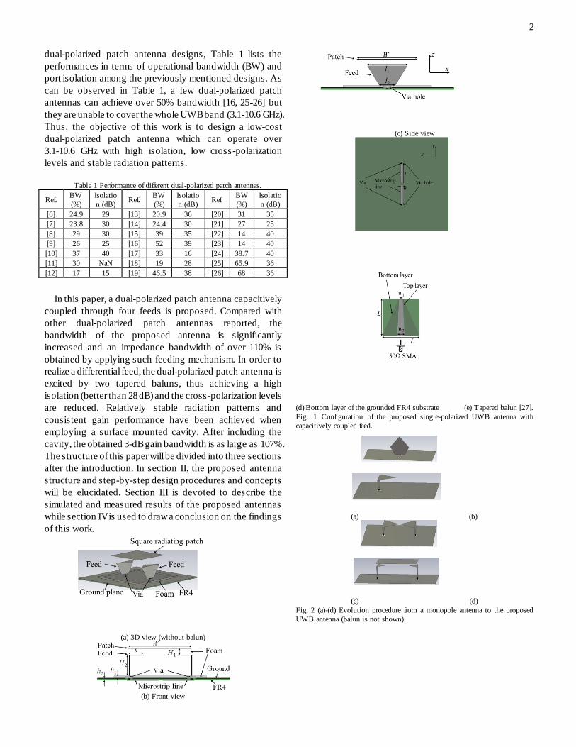
(a) 3D view (without balun)
(b) Front view
(c) Side view
(d) Bottom layer of the grounded FR4 substrate (e) Tapered balun [27].
Fig. 1 Configuration of the proposed single-polarized UWB antenna with
capacitively coupled feed.
(a) (b)
(c) (d)
Fig. 2 (a)-(d) Evolution procedure from a monopole antenna to the proposed
UWB antenna (balun is not shown).
Page 3
3
3 4 5 6 7 8 9 10 11-25
-20
-15
-10
-5
0
S (
dB
)
Frequency (GHz)
Fig. 2(a)
Fig. 2(b)
Fig. 2(c)
Fig. 2(d)
(a) Reflection coefficient
3 4 5 6 7 8 9 10 110
20
40
60
80
100
120
Rea
l (O
hm
)
Frequency (GHz)
Fig. 2(a)
Fig. 2(b)
Fig. 2(c)
Fig. 2(d)
3 4 5 6 7 8 9 10 11
-60
-40
-20
0
20
40
60
80
Imag
inar
y (
Oh
m)
Frequency (GHz)
Fig. 2(a)
Fig. 2(b)
Fig. 2(c)
Fig. 2(d)
(b) Real part (c) Imaginary part
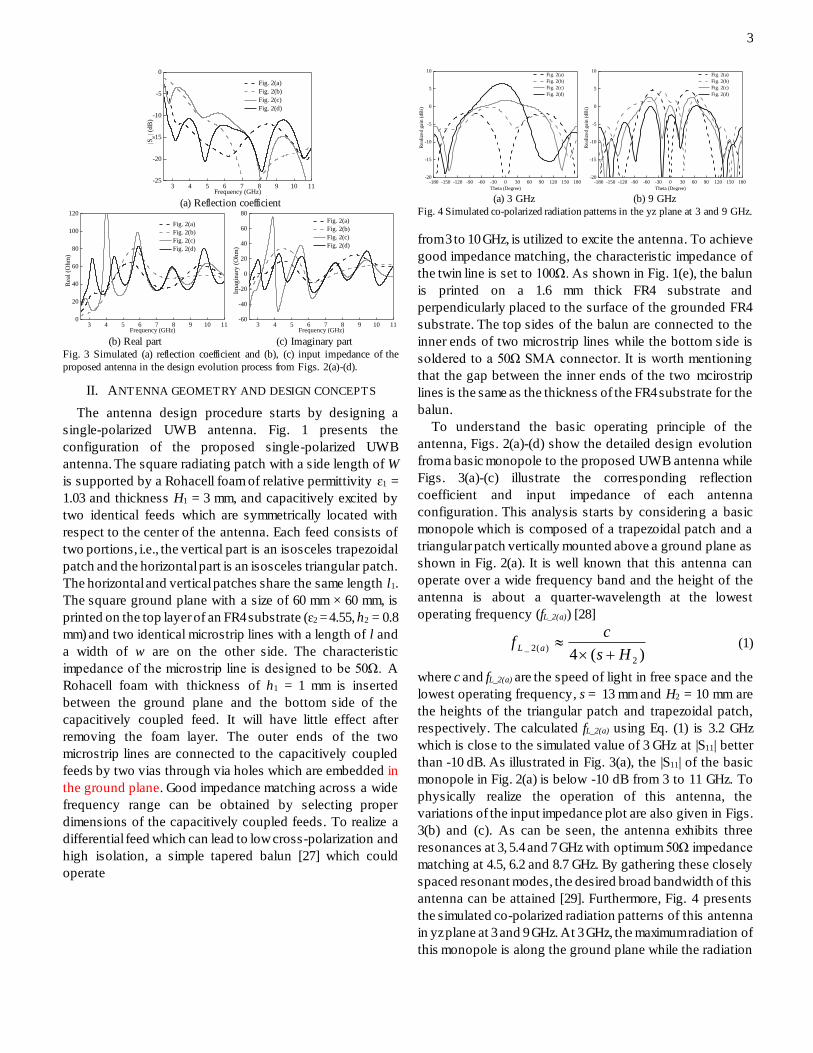
Fig. 3 Simulated (a) reflection coefficient and (b), (c) input impedance of the
proposed antenna in the design evolution process from Figs. 2(a)-(d).
II. ANTENNA GEOMETRY AND DESIGN CONCEPTS
The antenna design procedure starts by designing a
single-polarized UWB antenna. Fig. 1 presents the
configuration of the proposed single-polarized UWB
antenna. The square radiating patch with a side length of W
is supported by a Rohacell foam of relative permittivity ɛ1 =
1.03 and thickness H1 = 3 mm, and capacitively excited by
two identical feeds which are symmetrically located with
respect to the center of the antenna. Each feed consists of
two portions, i.e., the vertical part is an isosceles trapezoidal
patch and the horizontal part is an isosceles triangular patch.
The horizontal and vertical patches share the same length l1.
The square ground plane with a size of 60 mm × 60 mm, is
printed on the top layer of an FR4 substrate (ɛ2 = 4.55, h2 = 0.8
mm) and two identical microstrip lines with a length of l and
a width of w are on the other side. The characteristic
impedance of the microstrip line is designed to be 50Ω. A
Rohacell foam with thickness of h1 = 1 mm is inserted
between the ground plane and the bottom side of the
capacitively coupled feed. It will have little effect after
removing the foam layer. The outer ends of the two
microstrip lines are connected to the capacitively coupled
feeds by two vias through via holes which are embedded in
the ground plane. Good impedance matching across a wide
frequency range can be obtained by selecting proper
dimensions of the capacitively coupled feeds. To realize a
differential feed which can lead to low cross-polarization and
high isolation, a simple tapered balun [27] which could
operate
-180 -150 -120 -90 -60 -30 0 30 60 90 120 150 180-20
-15
-10
-5
0
5
10
Rea
lize
d g
ain (
dB
i)
Theta (Degree)
Fig. 2(a)
Fig. 2(b)
Fig. 2(c)
Fig. 2(d)
-180 -150 -120 -90 -60 -30 0 30 60 90 120 150 180-20
-15
-10
-5
0
5
10
Rea
lize
d g
ain (
dB
i)
Theta (Degree)
Fig. 2(a)
Fig. 2(b)
Fig. 2(c)
Fig. 2(d)
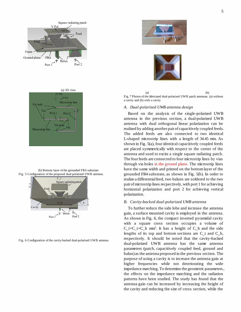
(a) 3 GHz (b) 9 GHz
Fig. 4 Simulated co-polarized radiation patterns in the yz plane at 3 and 9 GHz.
from 3 to 10 GHz, is utilized to excite the antenna. To achieve
good impedance matching, the characteristic impedance of
the twin line is set to 100Ω. As shown in Fig. 1(e), the balun
is printed on a 1.6 mm thick FR4 substrate and
perpendicularly placed to the surface of the grounded FR4
substrate. The top sides of the balun are connected to the
inner ends of two microstrip lines while the bottom side is
soldered to a 50Ω SMA connector. It is worth mentioning
that the gap between the inner ends of the two mcirostrip
lines is the same as the thickness of the FR4 substrate for the
balun.
To understand the basic operating principle of the
antenna, Figs. 2(a)-(d) show the detailed design evolution
from a basic monopole to the proposed UWB antenna while
Figs. 3(a)-(c) illustrate the corresponding reflection
coefficient and input impedance of each antenna
configuration. This analysis starts by considering a basic
monopole which is composed of a trapezoidal patch and a
triangular patch vertically mounted above a ground plane as
shown in Fig. 2(a). It is well known that this antenna can
operate over a wide frequency band and the height of the
antenna is about a quarter-wavelength at the lowest
operating frequency (fL_2(a)) [28]
)(4 2
)(2_Hs
cf aL
(1)
where c and fL_2(a) are the speed of light in free space and the
lowest operating frequency, s = 13 mm and H2 = 10 mm are
the heights of the triangular patch and trapezoidal patch,
respectively. The calculated fL_2(a) using Eq. (1) is 3.2 GHz
which is close to the simulated value of 3 GHz at |S11| better
than -10 dB. As illustrated in Fig. 3(a), the |S11| of the basic
monopole in Fig. 2(a) is below -10 dB from 3 to 11 GHz. To
physically realize the operation of this antenna, the
variations of the input impedance plot are also given in Figs.
3(b) and (c). As can be seen, the antenna exhibits three
resonances at 3, 5.4 and 7 GHz with optimum 50Ω impedance
matching at 4.5, 6.2 and 8.7 GHz. By gathering these closely
spaced resonant modes, the desired broad bandwidth of this
antenna can be attained [29]. Furthermore, Fig. 4 presents
the simulated co-polarized radiation patterns of this antenna
in yz plane at 3 and 9 GHz. At 3 GHz, the maximum radiation of
this monopole is along the ground plane while the radiation
Page 4
4
is shifted above the ground plane at 9 GHz and the main lobe
becomes narrower.
In order to achieve directional pattern and reduce the
overall height of the antenna, the vertical triangular patch is
bent to be parallel to the ground plane, as shown in Fig. 2(b).
This has shortened the height from 23 to 10 mm which
corresponds to a reduction of 56.5%. However, this
modification impairs the impedance matching at lower
operating band and shifts the lowest operating frequency to
4.4 GHz due to the coupling between the triangular patch and
the ground plane, as observed in Fig. 3(a). To further
investigate this, Figs. 3(b) and (c) show that, the change of
the structure has slight effect on the imaginary part of the
input impedance while the real part in the band from 3 to 4
GHz is significantly reduced, which deteriorates the
impedance matching. As expected, the folded monopole has
directional radiation though the maximum radiation at 3 GHz
is off boresight and pointed at -30°. The pattern can be
regarded as the contribution of the vertical patch and the
horizontal patch, as the maximum radiation of the vertical
patch is along the ground plane and the horizontal patch has
broadside radiation, as shown in Fig. 4.
In order to enhance the maximum radiation focus on the
broadside direction and reduce the cross -polarization level
through the differential feed technique, another identical
antenna element is added and mirrored into the antenna
structure, as illustrated in Fig. 2(c). As can be noticed in Fig.
3(a), the lowest operating frequency of the differential-fed
folded monopole is shifted down to 3 GHz while the
reflection coefficient in the low band is larger than -10 dB.
The input impedance in Figs. 3(b) and (c) show four series
resonances (3.25 GHz, 4.85 GHz, 7 GHz, 8.8 GHz) and four
parallel resonances (4 GHz, 5.9 GHz, 8 GHz, 10 GHz). As can
be observed, the real and imaginary parts have large
fluctuations in the low band, which indicates poor
impedance matching. Scrutinizing the pattern plot in Fig. 4
with this configuration, the main beam of this antenna is
along broadside at 3 GHz though the side lobe levels are
higher than the main beam at 9 GHz. This is caused by
various electrical lengths between the vertical patches at
different frequencies.
The final stage of the design process is to introduce a
parasitic patch to achieve good impedance matching over
the UWB band, as shown in Fig. 2(d) and Fig. 3. The
proposed antenna is similar as the L-shaped probe-fed patch
antenna [7, 29] while the L-probe is replaced by the L-shaped
patch and the impedance bandwidth is significantly
enhanced. The following formulas [29] are employed to
predict the lowest operating frequency (fL_2(d)) of the patch
antenna in Fig. 2(d)
er
dLWW
cf
)2(2)(2_
(2)
t
t
er
t
er
H
H
W
H
W
W
)813.0)(258.0(
)264.0)(3.0(
412.0
(3)
121 hHHH t (4)
where ɛer is the effective dielectric constant and is selected
as unity in this design. ΔW is the resonance edge extension
of the patch and Ht is the distance between the patch and the
ground plane. The initial values of the dimensions are: W = 27
mm, H1 = 3 mm, H2 = 9 mm and h1 = 1 mm. The corresponding
predicted fL_2(d) using Eq. (2-4) is 3.5 GHz. The discrepancy
between the predicted value and the simulated value at 3
GHz can be attributed to the coupling between the triangular
patches and the square radiating patch. As indicated in Fig.
3(a), the proposed single-polarized antenna can operate over
a wide frequency band covering the frequency range from 3
to 11 GHz for |S11| ≤ -10 dB. Moreover, as noticed in Figs. 3(b)
and (c), introducing the parasitic patch to the antenna
structure does not alter the resonant modes of the antenna in
Fig. 2(c), however it provides a stable impedance response
with less variation values of resistance (30 to 80 Ohm) and
reactance (-20 to 30 Ohm) over the operating frequency band.
To understand the contribution of this structure into the
radiation pattern, Fig. 4 describes the patterns at 3 and 9 GHz.
As can be clearly seen, the antenna has more directional
pattern compared to the antenna structure in Fig. 2(c) at 3
GHz. It should be noted that although the proposed antenna
and the designs in [7] and [30] have used L-shaped feeds,
the design processes are different. The antennas in [7] and
[30] are developed from traditional narrowband patch
antennas. The bandwidths of the antennas in [7] and [30] are
increased due to the use of the L-shaped feed while the initial
idea to use L-shaped feed in the proposed antenna is to
achieve directional radiation. Moreover, compared with
antennas in [7] and [30], the bandwidth of the proposed
antenna is significantly increased.
The performance of the tapered balun has been
investigated as it affects the overall performance of the
differential-fed antenna. It is found that the insertion loss of
the tapered balun is less than 2 dB and the reflection
coefficient is less than -10 dB over 3 to 11 GHz band;
including the phase difference of the balanced ports over the
same band is almost ±180ᵒ with relative phase errors around
±5ᵒ. These results can confirm that the tapered balun is
appropriate for feeding the proposed UWB antenna.
Page 5
5
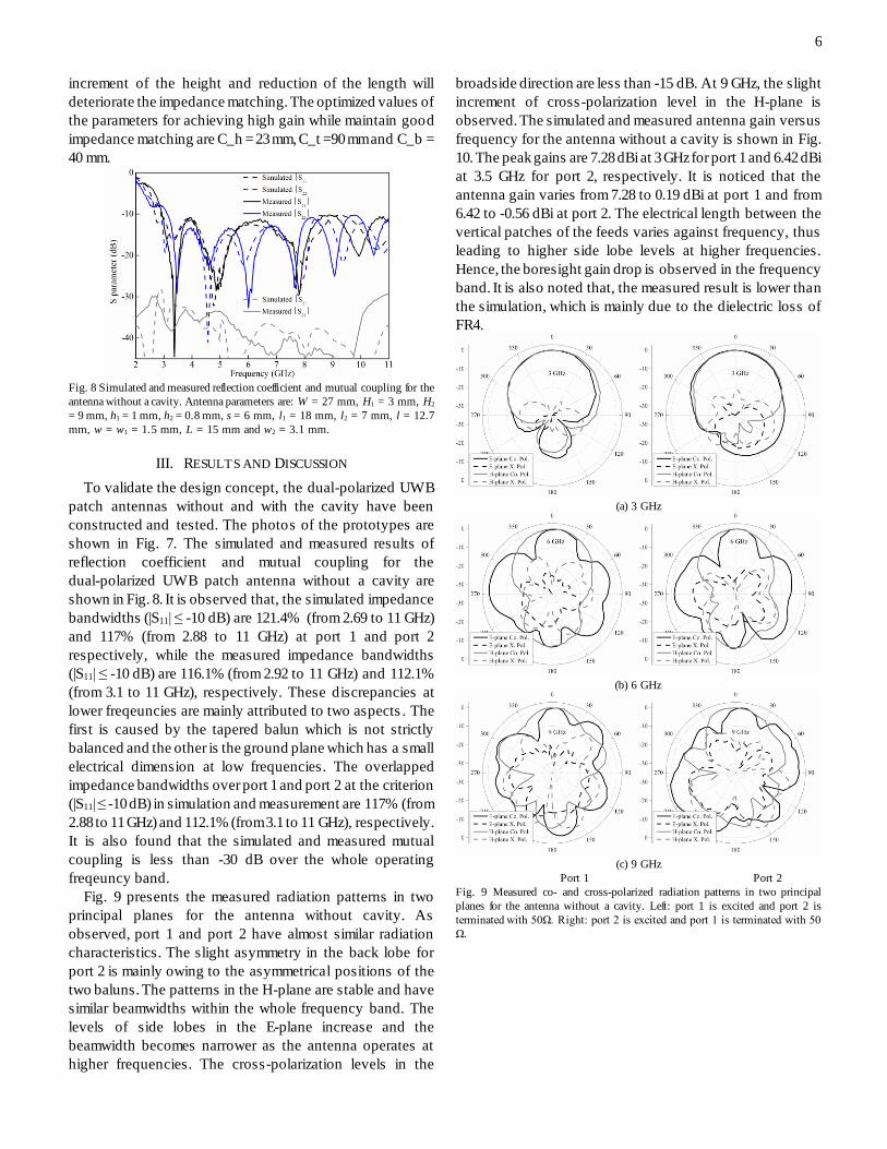
(a) 3D view
(b) Bottom layer of the grounded FR4 substrate
Fig. 5 Configuration of the proposed dual-polarized UWB antenna.
Fig. 6 Configuration of the cavity-backed dual-polarized UWB antenna
(a) (b)
Fig. 7 Photos of the fabricated dual-polarized UWB patch antennas. (a) without
a cavity and (b) with a cavity
A. Dual-polarized UWB antenna design
Based on the analysis of the single-polarized UWB
antenna in the previous section, a dual-polarized UWB
antenna with dual orthogonal linear polarization can be
realized by adding another pair of capacitively coupled feeds.
The added feeds are also connected to two identical
L-shaped microstrip lines with a length of 34.45 mm. As
shown in Fig. 5(a), four identical capacitively coupled feeds
are placed symmetrically with respect to the center of the
antenna and used to excite a single square radiating patch.
The four feeds are connected to four microstrip lines by vias
through via holes in the ground plane. The microstrip lines
have the same width and printed on the bottom layer of the
grounded FR4 substrate, as shown in Fig. 5(b). In order to
realize a differential feed, two baluns are soldered to the two
pair of microstrip lines recpectively, with port 1 for achieving
horizontal polarization and port 2 for achieving vertical
polarization.
B. Cavity-backed dual-polarized UWB antenna
To further reduce the side lobe and increase the antenna
gain, a surface mounted cavity is employed in the antenna.
As shown in Fig. 6, the compact inverted pyramidal cavity
with a square cross section occupies a volume of
C_t×C_t×C_h mm3. It has a height of C_h and the side
lengths of its top and bottom sections are C_t and C_b,
respectively. It should be noted that the cavity-backed
dual-polarized UWB antenna has the same antenna
parameters (patch, capacitively coupled feed, ground and
balun) as the antenna proposed in the previous section. The
purpose of using a cavity is to increase the antenna gain at
higher frequencies while not deteriorating the wide
impedance matching. To determine the geometric parameters ,
the effects on the impedance matching and the radiation
patterns have been studied. The study has found that the
antenna gain can be increased by increasing the height of
the cavity and reducing the size of cross section, while the
Page 6
6
increment of the height and reduction of the length will
deteriorate the impedance matching. The optimized values of
the parameters for achieving high gain while maintain good
impedance matching are C_h = 23 mm, C_t =90 mm and C_b =
40 mm.
Fig. 8 Simulated and measured reflection coefficient and mutual coupling for the
antenna without a cavity. Antenna parameters are: W = 27 mm, H1 = 3 mm, H2
= 9 mm, h1 = 1 mm, h2 = 0.8 mm, s = 6 mm, l1 = 18 mm, l2 = 7 mm, l = 12.7
mm, w = w1 = 1.5 mm, L = 15 mm and w2 = 3.1 mm.
III. RESULTS AND DISCUSSION
To validate the design concept, the dual-polarized UWB
patch antennas without and with the cavity have been
constructed and tested. The photos of the prototypes are
shown in Fig. 7. The simulated and measured results of
reflection coefficient and mutual coupling for the
dual-polarized UWB patch antenna without a cavity are
shown in Fig. 8. It is observed that, the simulated impedance
bandwidths (|S11| ≤ -10 dB) are 121.4% (from 2.69 to 11 GHz)
and 117% (from 2.88 to 11 GHz) at port 1 and port 2
respectively, while the measured impedance bandwidths
(|S11| ≤ -10 dB) are 116.1% (from 2.92 to 11 GHz) and 112.1%
(from 3.1 to 11 GHz), respectively. These discrepancies at
lower freqeuncies are mainly attributed to two aspects . The
first is caused by the tapered balun which is not strictly
balanced and the other is the ground plane which has a small
electrical dimension at low frequencies. The overlapped
impedance bandwidths over port 1 and port 2 at the criterion
(|S11| ≤ -10 dB) in simulation and measurement are 117% (from
2.88 to 11 GHz) and 112.1% (from 3.1 to 11 GHz), respectively.
It is also found that the simulated and measured mutual
coupling is less than -30 dB over the whole operating
freqeuncy band.
Fig. 9 presents the measured radiation patterns in two
principal planes for the antenna without cavity. As
observed, port 1 and port 2 have almost similar radiation
characteristics. The slight asymmetry in the back lobe for
port 2 is mainly owing to the asymmetrical positions of the
two baluns. The patterns in the H-plane are stable and have
similar beamwidths within the whole frequency band. The
levels of side lobes in the E-plane increase and the
beamwidth becomes narrower as the antenna operates at
higher frequencies. The cross-polarization levels in the
broadside direction are less than -15 dB. At 9 GHz, the slight
increment of cross-polarization level in the H-plane is
observed. The simulated and measured antenna gain versus
frequency for the antenna without a cavity is shown in Fig.
10. The peak gains are 7.28 dBi at 3 GHz for port 1 and 6.42 dBi
at 3.5 GHz for port 2, respectively. It is noticed that the
antenna gain varies from 7.28 to 0.19 dBi at port 1 and from
6.42 to -0.56 dBi at port 2. The electrical length between the
vertical patches of the feeds varies against frequency, thus
leading to higher side lobe levels at higher frequencies.
Hence, the boresight gain drop is observed in the frequency
band. It is also noted that, the measured result is lower than
the simulation, which is mainly due to the dielectric loss of
FR4.
(a) 3 GHz
(b) 6 GHz
(c) 9 GHz
Port 1 Port 2
Fig. 9 Measured co- and cross-polarized radiation patterns in two principal
planes for the antenna without a cavity. Left: port 1 is excited and port 2 is
terminated with 50Ω. Right: port 2 is excited and port 1 is terminated with 50
Ω.
Page 7
7
3 4 5 6 7 8 9 10 11-2
-1
0
1
2
3
4
5
6
7
8
Ante
nna
Gai
n (
dB
i)
Frequency (GHz)
Measurement (Port 1)
Measurement (Port 2)
Simulation (Port 1)
Simulation (Port 2)
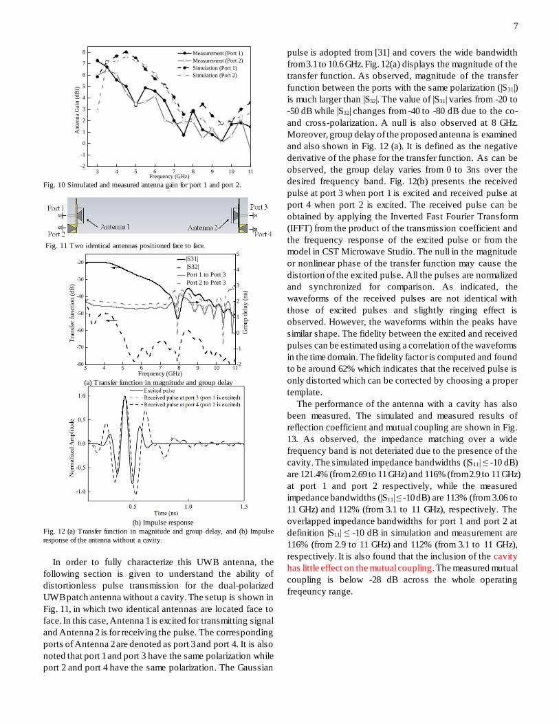
Fig. 10 Simulated and measured antenna gain for port 1 and port 2.
Fig. 11 Two identical antennas positioned face to face.
3 4 5 6 7 8 9 10 11-80
-70
-60
-50
-40
-30
-20
|S31|
|S32|
Port 1 to Port 3
Port 2 to Port 3
Frequency (GHz)
Tra
nsf
er f
unct
ion (
dB
)
-2
-1
0
1
2
3
4
5
Gro
up d
elay
(ns)
(a) Transfer function in magnitude and group delay
(b) Impulse response
Fig. 12 (a) Transfer function in magnitude and group delay, and (b) Impulse
response of the antenna without a cavity.
In order to fully characterize this UWB antenna, the
following section is given to understand the ability of
distortionless pulse transmission for the dual-polarized
UWB patch antenna without a cavity. The setup is shown in
Fig. 11, in which two identical antennas are located face to
face. In this case, Antenna 1 is excited for transmitting signal
and Antenna 2 is for receiving the pulse. The corresponding
ports of Antenna 2 are denoted as port 3 and port 4. It is also
noted that port 1 and port 3 have the same polarization while
port 2 and port 4 have the same polarization. The Gaussian
pulse is adopted from [31] and covers the wide bandwidth
from 3.1 to 10.6 GHz. Fig. 12(a) displays the magnitude of the
transfer function. As observed, magnitude of the transfer
function between the ports with the same polarization (|S31|)
is much larger than |S32|. The value of |S31| varies from -20 to
-50 dB while |S32| changes from -40 to -80 dB due to the co-
and cross-polarization. A null is also observed at 8 GHz.
Moreover, group delay of the proposed antenna is examined
and also shown in Fig. 12 (a). It is defined as the negative
derivative of the phase for the transfer function. As can be
observed, the group delay varies from 0 to 3ns over the
desired frequency band. Fig. 12(b) presents the received
pulse at port 3 when port 1 is excited and received pulse at
port 4 when port 2 is excited. The received pulse can be
obtained by applying the Inverted Fast Fourier Transform
(IFFT) from the product of the transmission coefficient and
the frequency response of the excited pulse or from the
model in CST Microwave Studio. The null in the magnitude
or nonlinear phase of the transfer function may cause the
distortion of the excited pulse. All the pulses are normalized
and synchronized for comparison. As indicated, the
waveforms of the received pulses are not identical with
those of excited pulses and slightly ringing effect is
observed. However, the waveforms within the peaks have
similar shape. The fidelity between the excited and received
pulses can be estimated using a correlation of the waveforms
in the time domain. The fidelity factor is computed and found
to be around 62% which indicates that the received pulse is
only distorted which can be corrected by choosing a proper
template.
The performance of the antenna with a cavity has also
been measured. The simulated and measured results of
reflection coefficient and mutual coupling are shown in Fig.
13. As observed, the impedance matching over a wide
frequency band is not deteriated due to the presence of the
cavity. The simulated impedance bandwidths (|S11| ≤ -10 dB)
are 121.4% (from 2.69 to 11 GHz) and 116% (from 2.9 to 11 GHz)
at port 1 and port 2 respectively, while the measured
impedance bandwidths (|S11| ≤ -10 dB) are 113% (from 3.06 to
11 GHz) and 112% (from 3.1 to 11 GHz), respectively. The
overlapped impedance bandwidths for port 1 and port 2 at
definition |S11| ≤ -10 dB in simulation and measurement are
116% (from 2.9 to 11 GHz) and 112% (from 3.1 to 11 GHz),
respectively. It is also found that the inclusion of the cavity
has little effect on the mutual coupling. The measured mutual
coupling is below -28 dB across the whole operating
freqeuncy range.
Page 8
8
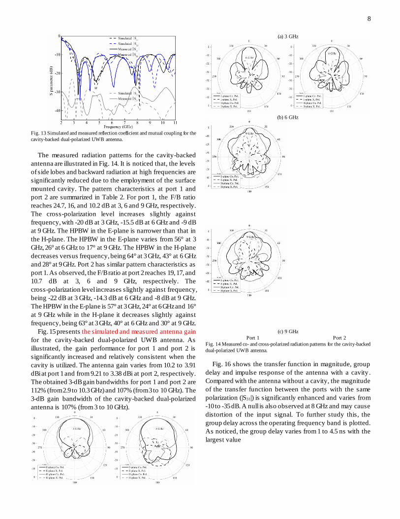
Fig. 13 Simulated and measured reflection coefficient and mutual coupling for the
cavity-backed dual-polarized UWB antenna.
The measured radiation patterns for the cavity-backed
antenna are illustrated in Fig. 14. It is noticed that, the levels
of side lobes and backward radiation at high frequencies are
significantly reduced due to the employment of the surface
mounted cavity. The pattern characteristics at port 1 and
port 2 are summarized in Table 2. For port 1, the F/B ratio
reaches 24.7, 16, and 10.2 dB at 3, 6 and 9 GHz, respectively.
The cross-polarization level increases slightly against
frequency, with -20 dB at 3 GHz, -15.5 dB at 6 GHz and -9 dB
at 9 GHz. The HPBW in the E-plane is narrower than that in
the H-plane. The HPBW in the E-plane varies from 56° at 3
GHz, 26° at 6 GHz to 17° at 9 GHz. The HPBW in the H-plane
decreases versus frequency, being 64° at 3 GHz, 43° at 6 GHz
and 28° at 9 GHz. Port 2 has similar pattern characteristics as
port 1. As observed, the F/B ratio at port 2 reaches 19, 17, and
10.7 dB at 3, 6 and 9 GHz, respectively. The
cross-polarization level increases slightly against frequency,
being -22 dB at 3 GHz, -14.3 dB at 6 GHz and -8 dB at 9 GHz.
The HPBW in the E-plane is 57° at 3 GHz, 24° at 6 GHz and 16°
at 9 GHz while in the H-plane it decreases slightly against
frequency, being 63° at 3 GHz, 40° at 6 GHz and 30° at 9 GHz.
Fig. 15 presents the simulated and measured antenna gain
for the cavity-backed dual-polarized UWB antenna. As
illustrated, the gain performance for port 1 and port 2 is
significantly increased and relatively consistent when the
cavity is utilized. The antenna gain varies from 10.2 to 3.91
dBi at port 1 and from 9.21 to 3.38 dBi at port 2, respectively.
The obtained 3-dB gain bandwidths for port 1 and port 2 are
112% (from 2.9 to 10.3 GHz) and 107% (from 3 to 10 GHz). The
3-dB gain bandwidth of the cavity-backed dual-polarized
antenna is 107% (from 3 to 10 GHz).
(a) 3 GHz
(b) 6 GHz
(c) 9 GHz
Port 1 Port 2
Fig. 14 Measured co- and cross-polarized radiation patterns for the cavity-backed
dual-polarized UWB antenna.
Fig. 16 shows the transfer function in magnitude, group
delay and impulse response of the antenna with a cavity .
Compared with the antenna without a cavity, the magnitude
of the transfer function between the ports with the same
polarization (|S31|) is significantly enhanced and varies from
-10 to -35 dB. A null is also observed at 8 GHz and may cause
distortion of the input signal. To further study this, the
group delay across the operating frequency band is plotted.
As noticed, the group delay varies from 1 to 4.5 ns with the
largest value
Page 9
9
3 4 5 6 7 8 9 10 11-2
-1
0
1
2
3
4
5
6
7
8
9
10
11
12
13
14
Ante
nna
Gai
n (
dB
i)
Frequency (GHz)
Measurement (Port 1)
Measurement (Port 2)
Simulation (Port 1)
Simulation (Port 2)
Fig. 15 Simulated and measured antenna gain for the cavity-backed antenna
3 4 5 6 7 8 9 10 11-80
-70
-60
-50
-40
-30
-20
-10
|S31|
|S32|
Port 1 to Port 3
\ Port 2 to Port 3
Frequency (GHz)
Tra
nsf
er f
unct
ion (
dB
)
-2
-1
0
1
2
3
4
5
Gro
up d
elay
(ns)
(a) Transfer function in magnitude and group delay
(b) Impulse response
Fig. 16 (a) Transfer function in magnitude and group delay, and (b) Impulse
response of the antenna with a cavity.
close to 8 GHz. This observation is caused due to the phase
and pattern distortion and gain drop near 8 GHz, which is
shown in Fig. 15. Fig. 16 (b) shows the received pulse at port
3 when port 1 is excited and received pulse at port 4 when
port 2 is excited. All the pulses are normalized and
synchronized for comparison. The fidelity factor of the
antenna reaches around 86%. Compared with the antenna
without a cavity, the fidelity is increased by 24% after
including the cavity.
Table 2 Summary of pattern characteristics for the cavity-back dual-polarized UWB antenna at 3, 6 and 9 GHz.
Frequency
port 1 port 2
Gain
(dBi)
F/B ratio
(dB)
X. pol.
level (dB)
HPBW (°) Gain
(dBi)
F/B ratio
(dB)
X. pol.
level (dB)
HPBW (°)
E plane H plane E plane H plane
3 GHz 9 24.7 -20 56 64 7.32 19 -22 57 63
6 GHz 10.2 16 -15.5 26 43 8.36 17 -14.3 24 40
9 GHz 8.28 10.2 -9 17 28 7.66 10.7 -8 16 30
F/B ratio is front-to-back ratio; HPBW is half-power beamwidth; X. pol. is cross-polarization.
IV. CONCLUSION
A novel dual-polarized UWB patch antenna excited by
two tapered baluns has been presented. It consists of a
square patch and four capacitively coupled feeds. The
current distributions on the square patch at different
frequencies have been studied for understanding the
operating principle. Two antenna designs with a planar
reflector or a surface mounted cavity have been designed,
fabricated and tested. Compared with the antenna with a
planar reflector, the cavity-backed patch antenna can
operate over a wide frequency range with an impedance
bandwidth of 112%. The measured antenna gain ranges from
10.2 to 3.91 dBi and from 9.21 to 3.38 dBi for port 1 and port 2,
respectively. The 3-dB gain bandwidth of up to107.6% is
achieved and the measured isolation is over 28 dB within the
whole frequency band.
V. REFERENCES
[1] P. Li, J. Liang, and X. D. Chen, "Study of printed elliptical/circular slot
antennas for ultrawideband applications," IEEE Trans. Antennas Propag.,
vo. 54, no. 6, 2006, pp. 1670-1675.
[2] Z. N. Chen, M. J. Ammann, X. M. Qing, X. H. Wu, T. S. P. See, and A.
L. Cai, "Planar antennas," IEEE Microw. Mag., vol. 7, 2006, pp. 63-73.
Page 10
10
[3] H. G. Schantz, "A brief history of UWB antennas," IEEE A&E Syst. Mag.,
vol. 19, no. 4, 2004, pp. 22-26.
[4] X. Li, G. Adamiuk, M. Janson, and T. Zwick, “ Polarization diversity in
ultra-wideband imaging systems,” 2010 IEEE International Conference
on Ultra-Wideband (ICUWB), vol. 1, pp. 1-4, 2010.
[5] L. Zwirello, G. Adamiuk, W. Wiesbeck, and T. Zwick, “ Measurement
verification of dual-orthogonal polarized UWB monopulse radar system,”
2010 IEEE International Conference on Ultra-Wideband (ICUWB), vol.
2, pp. 1-4, 2010.
[6] L. Siu, H. Wong, and K. M. Luk, “ A dual-polarized magneto-electric
dipole with dielectric loading,” IEEE Trans. Antennas Propag., vol. 57,
no. 7, 2009, pp. 616-623.
[7] H. Wong, K. L. Lau, and K. M. Luk, “ Design of dual-polarized L-probe
patch antenna arrays with high isolation,” IEEE Trans. Antennas Propag.,
vol. 52, no. 1, 2004, pp. 45-52.
[8] Y. X. Guo, K. W. Khoo, and L. C. Ong, “ Wideband dual-polarized patch
antenna with broadband baluns” IEEE Trans. Antennas Propag., vol. 55,
no. 1, 2007, pp. 78-83.
[9] H. W. Lai and K. M. Luk, “ Dual polarized patch antenna fed by
meandering probes” IEEE Trans. Antennas Propag., vol. 55, no. 9, 2007,
pp. 2625-2627.
[10] K. S. Ryn and A. A. Kishk, “ Wideband dual-polarized microstrip patch
aexcited by hook shaped probe,” IEEE Trans. Antennas Propag., vol. 56,
no. 12, 2008, pp. 3645-3649.
[11] J. Huang, Z. Hussein, and A. Petros, “ A wide-band dual-polarized VHF
microstrip antenna for global sensing of sea ice thickness,” IEEE Antennas
and Propagation Society International Symposium, vol. 2B, pp. 684-687,
2005.
[12] J. L. Vazquez-Roy, V. Krozer, and J. Dall, “ Wideband dual-polarization
microstrip patch antenna array for airborne ice sounder,” IEEE Antennas
Propag. Mag., vol. 54, no. 4, pp. 98-107, 2012.
[13] S. Gao, L. W. Li, M. S. Leong, and T. S. Yeo, “ Dual-polarized
slot-coupled planar antenna with wide bandwidth,” IEEE Trans. Antennas
Propag., vol. 51, no. 3, 2003, pp. 441-448.
[14] S. Gao, L. W. Li, M. S. Leong, and T. S. Yeo, “ A broad-band
dual-polarized microstrip patch antenna with aperture coupling,” IEEE
Trans. Antennas Propag., vol. 51, no. 4, 2003, pp. 898-900.
[15] M. Barba, “ A high-isolation, wideband and dual-linear polarization patch
antenna,” IEEE Trans. Antennas Propag., vol. 56, no. 5, 2008, pp.
1472-1476.
[16] K. Ghorbani and R. B. Waterhouse, “ Dual polarized wide-band aperture
stacked patch antennas,” IEEE Trans. Antennas Propag., vol. 52, no. 8,
2004, pp. 2171-2174.
[17] A. A. Serra, P. Nepa, G. Manara, G. Tribellini, and S. Cioci, “ A
wide-band dual-polarized stacked patch antenna,” IEEE Antennas Wireless
Propag. Lett., vol. 6, 2007, pp. 141-143.
[18] R. C. Paryani, P. F. Wahid, and N. Behdad, “ A wideband, dual-polarized,
substrate-integrated cavity-backed slot antenna,” IEEE Antennas Wireless
Propag. Lett., vol. 9, 2010, pp. 645-648.
[19] B. Li, Y. Z. Yin, W. Hu, Y. Ding, and Y. Zhao, “ Wideband
dual-polarized patch antenna with low cross polarization and high
isolation,” IEEE Antennas Wireless Propag. Lett. , vol. 11, 2012, pp.
427-430.
[20] S. G. Zhou, P. K. Tan, and T. H. Chio, “ Low-profile, wideband
dual-polarized antenna with high isolation and low cross polarization,”
IEEE Antennas Wireless Propag. Lett. , vol. 11, 2012, pp. 1032-1035.
[21] Y. X. Guo, K. M. Luk, and K. F. Lee, “ Broadband dual polarization patch
element for cellar-phone base stations,” IEEE Trans. Antennas Propag.,
vol. 50, no. 2, 2002, pp. 251-253.
[22] T. W. Chiou and K. L. Wong, “ Broad-band dual-polarized single
microstrip patch antenna with high isolation and low cross polarization,”
IEEE Trans. Antennas Propag., vol. 50, no. 3, 2002, pp. 399-401.
[23] C. Y. D. Sim, C. C. Chang, and J. S. Row, “ Dual-feed dual-polarized
patch antenna with low cross polarization and high isolation,” IEEE
Trans. Antennas Propag., vol. 57, no. 10, 2009, pp. 3405-3409.
[24] J. J. Xie, Y. Z. Yin, J. H. Wang, and X. L. Liu, “ Wideband
dual-polarised electromagnetic-fed patch antenna with high isolation and
low cross-polarisation,” Electron. Lett., vol. 49, no. 3, 2013, pp.
171-173.
[25] B. Q. Wu and K. M. Luk, “ A broadband dual-polarized magneto-electric
dipole antenna with simple feeds,” IEEE Antennas Wireless Propag. Lett. ,
vol. 8, 2009, pp. 60-63.
[26] Q. Xue, S. W. Liao, and J. H. Xu, “ A differentially-driven dual-polarized
magneto-electric dipole antenna,” IEEE Trans. Antennas Propag., vol.
61, no. 1, 2013, pp. 425-430.
[27] A. Mehdipour, K. M. Aghdam, M. R. K. Khatib, and R. F. Dana, “ A
practical feeder for differential elliptical antennas in ultra-wideband
applications,” Microw. Opt. Technol. Lett., vol. 50, no. 8, pp.
2103-2107, 2008.
[28] S. Y. Suh, W. L. Stutzman, and W. A. Davis, “ A new ultrawideband
printed monopole antenna: the planar inverted cone antenna (PICA)”, IEEE
Trans. Antennas Propag., vol. 52, no. 5, 2004, pp. 1361-1365.
[29] B. Allen, M. Dohler, E. E. Okon, W. Q. Malik, A. K. Brown, and D. J.
Edwards, Ultra-wideband Antennas and Propagation for
Communications, Radar and Imaging, John Wiley & Sons, 2007.
[30] C. L. Mark, K. M. Luk, K. F. Lee, and Y. L. Chow, “ Experimental study
of a microstrip patch antenna with an L-shaped probe,” IEEE Trans.
Antennas Propag., vol. 48, no. 5, 2000, pp. 777-783.
[31] C. H. See, R. A. Abd-Alhameed, H. I. Hraga, N. J. McEwan, P. S. Excell,
and J. M. Noras, “ A low-profile ultra-wideband modified planar inverted-F
antenna,” IEEE Trans. Antennas Propag., vol. 61, no. 1, 2013, pp.
100-108.
Fuguo Zhu was born in Jiangsu, China, in 1986. He
received his M.Sc. degree in electromagnetic theory
and microwave technology from Northwestern
Polytechical University, Xi’an, P.R. China, in 2011,
and his Ph.D. degree in Electronic Engineering from
the University of Kent, Canterbury, UK, in 2014.
He worked as a Ph.D. student at Surrey Space
Centre, University of Surrey, Guildford, UK, from
October 2010 to March 2013. His research interests
include UWB antenna, dual-polarized UWB antenna,
and UWB antenna array.
Steven Gao (M’01) received the Ph.D. degree in
microwave engineering from Shanghai University,
Shanghai, China, in 1999. He is a Professor in
antennas and microwave/millimeter-wave systems at
University of Kent, UK. His research covers space
antennas, smart antennas, phased arrays,
millimeter-wave antennas, high-efficiency
RF/microwave power amplifiers, satellite
communications, UWB radars, synthetic-aperture
radars, EM modeling and small satellites. He was a Senior Lecturer and Head of
Space Antennas and Microwave System Group at Surrey Space Center,
University of Surrey, UK.
He is General Chair of Loughborough Antennas and Propagation
International Conference, UK, 2013. He is a co-editor of <<Space Antenna
Handbook>> (Wiley, 2012), published over 160 technical papers, 8 book
chapters and holds several patents in smart antennas and RF. He received "URSI
Young Scientist Award" from International Union of Radio Science, 2002,
"Japan Society of Promotion Science Fellowship Award", Japan, 2005, “ Best
Paper Award”, LAPC, UK, 2012, etc. He has been a Principal Investigator for
many projects including "Millimeter-wave intelligent array antennas for
next-generation mobile satellite communications" (FLEXWIN, funded by
European Union FP7 ICT Program), etc.
Anthony T.S. Ho (M’89-SM’94) received the B.Sc.
(Hons) degree in physical electronics from
Northumbria University, Newcastle upon Tyne, U.K.,
in 1979, the M.Sc. degree in applied optics from
Imperial College London, London, U.K., in 1980, and
the Ph.D. degree in digital image processing from
King’s College London, London, U.K., in 1983.
He holds a Personal Chair in Multimedia Security
and has been Head of Department of Computing, University of Surrey, Surrey,
U.K., since 2010. After graduation, he worked in industry for 11 years in the
U.K. and Canada. From 1994 to 2005, he was a Senior Lecturer and then
Associate Professor at Nanyang Technological University (NTU), Singapore. He
has published more than 130 articles in international journals and conference
proceedings as well as eight international patents granted related to watermarking
Page 11
11
and steganography. He is the Editor-in-Chief of the international journal
Information Security Technical Report published by Elsevier.
Prof. Ho is a Fellow of Institution of Engineering and Technology (FIET),
Fellow of Institute of Physics (FInstP), and Fellow of British Computer Society
(FBCS).
Raed A. Abd-Alhameed (M’11-SM’13) received the
B.Sc. and M.Sc. degrees from Basrah University,
Basrah, Iraq, in 1982 and 1985, respectively, and the
Ph.D degree from the University of Bradford, West
Yorkshire, UK, in 1997, all in electrical engineering.
He is a Professor of electromagnetic and radio
frequency (RF) engineering in the School of
Engineering, Design, and Technology at the
University of Bradford, Bradford, U.K. He has over 20
years research experience in RF designs, antennas and
electromagnetic computational techniques and has published over 400 academic
journals and referred conference papers. He has led several funded projects from
EPSRC, Health Department, Technology Strategy Board and Industry. His
current research interests include hybrid electromagnetic, EMC, low SAR
antennas, active antennas, beam steering antennas, MIMO antennas, RF
predistorter including biological cell modeling for breast cancer applications.
Prof. Abd-Alhameed is the Fellow of the Institution of Engineering and
Technology, Fellow of Higher Education Academy, and a Chartered Engineer.
He is the Chair of several successful workshops on Energy Efficient and
Reconfigurable Transceivers (EERT): Approach towards Energy Conservation
and CO2 Reduction that addresses the biggest challenges for the future wireless
systems.
Chan H. See received a first class BEng Honours degree
in Electronic, Telecommunication and Computer
Engineering and a PhD degree from the University of
Bradford, UK in 2002 and 2007 respectively. Currently,
he is working as a senior research fellow in the Antennas
and Applied Electromagnetics research group within the
Electronics, Communications and Information Systems
Engineering (ECISE), to support various projects
related to sensors and antennas for the water industry. He
has published over 100 journal articles and conference
papers. He is a coauthor for 1 book and 1 book chapter.
He was a recipient of two Young Scientist Awards from International Union of
Radio Science (URSI) and Asia-Pacific Radio Science Conference (AP-RASC)
in 2008 and 2010 respectively. Dr See is a Chartered Engineer and Member of the
Institution of Engineering and Technology (MIET). He has an NVQ level 4 in
Management from the Chartered Management Institute.
Tim WC Brown (S’00-M’04) graduated from the
University of Surrey in 1999 with a BEng in Electronic
Engineering and since graduated with a PhD in antenna
diversity for mobile terminals in the Centre for
Communication Systems Research (CCSR) in 2004.
Since completing his doctoral research, he has
continued his research interests in antennas,
propagation and radio frequency (RF) engineering.
This has included postdoctoral research from
2004-2006 at Aalborg University, Denmark and his
present post as a lecturer in RF, antennas and propagation at CCSR. His current
research interests include mobile terminal antennas, satellite communications,
multiple input multiple output (MIMO), ultra wideband (UWB) radar, radio
frequency identification (RFID), near field communications (NFC), vehicular
technologies and future wireless.
Jianzhou Li received the B.E., M.E. and Ph.D. degrees from Northwestern
Polytechnical University, China in 1995, 2002 and 2005, respectively. From
2008 to 2009, he was a visiting scholar at Surrey Space Centre, University of
Surrey, UK. Currently he works as associate professor at School of Electronics
and Information, Northwestern Polytechnical University, China. His research
interests include computational electromagnetics and printed antennas.
Gao Wei was born in Shaanxi, China, in 1963. He received the Ph.D. degree
from Northwestern Polytechnical University, Xi’an, China, in 2008. Currently,
he is a professor at School of Electronics and Information, Northwestern
Polytechnical University, China. His research interests include microwave
measurement and microwave communication.
Jiadong Xu was born in Nanjing, China, in 1948. He received the M.Sc. degree
from Northwestern Polytechnical University, Xi’an, China, 1981. Since 1990,
he has been with School of Electronics and Information, Northwestern
Polytechnical University, China, as a full professor working on antenna design,
EM scattering theory and microwave measurement.