WIRELESS LOCALIZATION USING ULTRA - WIDEBAND SIGNALS
Liuqing Yang 1 and Huilin Xu 2 1 Colorado State University, Fort Collins, CO 2 QUALCOMM Incorporated, San Diego, CA
REVIEWING THIS chapter, the reader will have an overall understanding of
ultra - wideband ( UWB ) - related localization and ranging techniques including
systems, algorithms, performance analyses, and comparisons. In Section 8.1 , we
briefl y review the background knowledge of UWB. Section 8.2 introduces the
recent research progress on UWB localization including fi ngerprinting and
geometric techniques. Since time - based localization is most widely adopted for
UWB, Sections 8.3 and 8.4 are dedicated to time - of - arrival (TOA) estimation with
UWB signals.
8.1 INTRODUCTION TO UWB
According to the U.S. Federal Communications Commission ( FCC ), UWB refers to the wireless technology that can access the frequency spectrum larger than 500 MHz or a fractional bandwidth exceeding 20%. Since the U.S. permitted the operation of UWB devices in shared or nongovernment frequency bands [1] , UWB has attracted broad interests in areas of wireless communications and localization. Due to the unique advantages including wall penetration capability, low transmission power, simple transceiver structure, and high temporal as well as spatial resolutions, UWB can potentially provide huge capacity and centimeter - level localization accuracy.
8.1.1 Regularization
In 2002, the United States permitted the unlicensed use of UWB technology in shared or nongovernment frequency bands [1] . The FCC order specifi es operational
246 CHAPTER 8 WIRELESS LOCALIZATION USING ULTRA-WIDEBAND SIGNALS
limitations for applications including imaging systems and vehicular radar, indoor, and handheld UWB systems. Depending on the implementation scenario, a UWB localization device can be categorized into any of these systems. In order to avoid harmful interference from UWB devices to existing systems, FCC has set the emis-sion limit for each type of UWB implementation, which is called the emission mask. For example, the highest power spectral density ( PSD ) emission level for indoor UWB devices is − 41.3 dBm/MHz in the range of 3.1 – 10.6 GHz (see Fig. 8.1 ).
In Europe, the European Commission ’ s ( EC ) Radio Spectrum Committee approved the operation of UWB in 2006 [2] . EC identifi ed the frequency bands of 3.4 – 5.0 GHz and 6.0 – 8.5 GHz with potential extension to 9 GHz for UWB devices. In Singapore, the Info - communications Development Authority of Singapore ( IDA ) was established to support the development of UWB in 2003. In Japan, the UWB spectral mask was approved in 2006 [3] .
8.1.2 Transmission Approaches
A UWB spectrum can be accessed either by generating a series of extremely short duration pulses or the aggregation of a number of narrowband subcarriers having a bandwidth over 500 MHz. This leads to two transmission approaches for UWB technology, namely, impulse radio ( IR ) and multiband orthogonal frequency division multiplexing ( MB - OFDM ). IR transmits pulses that occupy the entire allowable frequency band. In MB - OFDM, the UWB spectrum is exploited by transmitting orthogonal frequency division multiplexing (OFDM) symbols on several sub - bands in a frequency hopping manner.
IR transmits information by altering the positioning, amplitude, polarity, or shape of the UWB pulse, which corresponds to pulse position modulation ( PPM ),
Figure 8.1 FCC emission limits for indoor UWB communications.
pulse amplitude modulation ( PAM ), on – off keying ( OOK ), or pulse shape modula-tion ( PSM ). The continuous transmission of uniformly spaced pulses gives rise to strong spectrum spikes occurring at integer multiples of the pulse repetition fre-quency. Therefore, time hopping ( TH ) and direct sequence ( DS ) techniques are adopted to mitigate the frequency spikes by randomizing the pulse train. TH and DS can also enable multiaccess in UWB systems. TH is often applied to low data rate UWBs with low pulse duty cycles. DS is suitable for medium to high data rate transmissions with high duty cycles.
MB - OFDM accesses the entire UWB spectrum by altering the carrier fre-quency according to some time – frequency ( TF ) hopping pattern. The advantages of MB - OFDM include high spectral effi ciency, resilience against narrowband interfer-ence, and tolerance to multipath effects. Therefore, MB - OFDM is very suitable for high data rate short - range applications. In addition, due to the multiband operation, MB - OFDM can achieve higher - frequency diversity than single - band OFDM.
8.1.3 Standards
After the FCC ’ s authorization of UWB, attempts have been made by the Institute of Electrical and Electronics Engineers ( IEEE ) to incorporate UWB into technical standards as the PHY technology. The standard groups include the IEEE 802.15.3a for high - rate wireless personal area network s ( WPAN s) in short range less than 10 m and the IEEE 802.15.4a for low - rate WPANs.
The IEEE 802.15.3a task group (TG3a) was established to identify a higher data rate amendment to IEEE 802.15.3 for an alternate physical layer ( PHY ). Two UWB - based proposals used to compete for the fi nal approval. One is the DS - UWB and the other is the MB - OFDM. MB - OFDM standards of the European Computer Manufacturers Association ( ECMA ) have been accepted by the International Organization for Standardization ( ISO ) [4, 5] . In ECMA MB - OFDM, the entire UWB spectrum of 3.1 – 10.6 GHz is divided into 14 bands each with a bandwidth of 528 MHz. The 14 bands are further grouped into six groups as shown in Figure 8.2 . OFDM symbols are transmitted within a group by switching the frequency band according to the TF code. TG3a was offi cially disbanded in 2006 due to the regula-tory and market uncertainty.
The IEEE standard 802.15.4a is an improved version of IEEE 802.15.4 with an alternative UWB - based PHY. It provides data communications and high - accuracy
Figure 8.2 ECMA MB - OFDM bands labeled with the corresponding center frequencies.
248 CHAPTER 8 WIRELESS LOCALIZATION USING ULTRA-WIDEBAND SIGNALS
positioning for low data rate networking with ultralow complexity, ultralow power consumption, and scalable data rates of 110 and 851 kbps and 6.81 and 27.24 Mbps. The PHY can operate on three different bands: the subgigahertz band (250 – 750 MHz), the low band (3.1 – 5.0 GHz), and the high band (6.0 – 10.6 GHz). IEEE 802.15.4a is the fi rst UWB standard that incorporates wireless localization. It supports both the two - way and one - way ranging protocols. In 2007, the IEEE 802.15.4a standard was approved by the IEEE Standards Association ( SA ) [6] .
8.1.4 UWB Channels
Due to the huge bandwidth of UWB signals, the UWB channel is signifi cantly dif-ferent from narrowband wireless channels. UWB channels are characterized by the dense multipaths that come in clusters. Since a deterministic channel model cannot describe the wireless propagation environment very well, the UWB channel is usually studied by extracting a statistical model from measurements. Parameters of the model refl ect the statistical properties of various propagation environments.
As discussed in Chapter 4 , the wireless channel is usually expressed by the following model:
h t h tl l
l
( ) = −( )=
∞
∑ δ τ0
, (8.1)
where h l and τ l are the amplitude and delay of the l th channel path. In UWB chan-nels, multipath components come in clusters, each of which is otherwise resolved as a single path by narrowband signals. Modeling of UWB channels is often based on the Saleh – Valenzuela ( S - V ) model with impulse response [7] :
h t j t Tm n m n m m n
nm
( ) = ( ) − −( )+∞
=
+∞
∑∑ α θ δ τ, , ,
=00
exp , (8.2)
where α m , n and θ m , n are the multipath gain and phase, respectively. T m is the arrival time of the fi rst path of the m th cluster and τ m , n is the delay of the n th ray inside the m th cluster relative to T m . Theoretically, each channel realization can contain an infi nite number of multipath components, but in practice, the number of multipaths is usually considered to be fi nite by ignoring the very weak trailing paths.
In the S - V model, the phases of multipath component θ m , n are modeled as independent uniform random variables in [0, 2 π ), and the amplitude α m , n is an inde-pendent Rayleigh random variable with the power delay profi le ( PDP )
E E e em nTm m nα α τ γ
,2
0,02{ } = { } − −Γ , , (8.3)
where Γ and γ are the constant decay rates for clusters and rays, respectively. The cluster and ray arrival times are represented by Poisson distributed random variables with arrival rates Λ and λ , respectively, according to the following probability density function s ( PDF s):
p T T T T mm m m m− −( ) = − −( )[ ] >1 1 , 0Λ Λexp (8.4)
and
p nm n m n m n m nτ τ λ λ τ τ, , 1 1 0−( ) −( )( ) = − −( )[ ] >exp , ., , (8.5)
An example of the PDP of the S - V model is illustrated in Figure 8.3 .
Example 8.1
Generate PDP realizations for the S - V channel model in MATLAB with the follow-ing parameters: Λ = 1/200 ns − 1 , λ = 1/20 ns − 1 , Γ = 60 ns, and γ = 20 ns. Count the number of clusters contained in each PDP realization.
Solution
The MATLAB codes in Chapter_8_Example_1.m generate PDP realizations for the S - V channel model. MATLAB codes can be found online at ftp://ftp.wiley.com/public/sci_tech_med/matlab_codes . In the fi rst while loop, clusters are generated with their arrival times determined by PDF (Eq. 8.4 ). The loop terminates if the newly generated cluster arrival time is larger than the maximum channel delay, and this cluster arrival time is discarded. In the for loop, rays are generated for each cluster with their arrival times determined by PDF (Eq. 8.5 ). Then, the power of each ray is calculated according to Equation 8.3 . For each cluster, the while loop terminates if the newly generated ray arrival time is larger than the maximum channel delay. When log scale is used for the y - axis, it is clear that both clusters and rays decay exponentially.
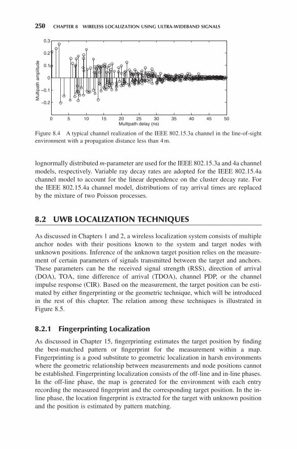
The IEEE 802.15.3a and 4a UWB channels are modifi ed versions of the S - V model with the main differences summarized as follows [8, 9] . Both UWB channels have incorporated the path loss and the lognormally distributed shadowing. The phase θ m , n is constrained to 0 or π with equal probability in the IEEE 802.15.3a channel model, which results in a real valued baseband channel model (see Fig. 8.4 ). Distributions of the amplitude α m , n are modifi ed to better fi t the UWB channel parameters. The lognormal distribution and the Nakagami - m distribution with the
Figure 8.3 PDP of the Saleh – Valenzuela channel model.
250 CHAPTER 8 WIRELESS LOCALIZATION USING ULTRA-WIDEBAND SIGNALS
lognormally distributed m - parameter are used for the IEEE 802.15.3a and 4a channel models, respectively. Variable ray decay rates are adopted for the IEEE 802.15.4a channel model to account for the linear dependence on the cluster decay rate. For the IEEE 802.15.4a channel model, distributions of ray arrival times are replaced by the mixture of two Poisson processes.
8.2 UWB LOCALIZATION TECHNIQUES
As discussed in Chapters 1 and 2 , a wireless localization system consists of multiple anchor nodes with their positions known to the system and target nodes with unknown positions. Inference of the unknown target position relies on the measure-ment of certain parameters of signals transmitted between the target and anchors. These parameters can be the received signal strength ( RSS ), direction of arrival ( DOA ), TOA, time difference of arrival ( TDOA ), channel PDP, or the channel impulse response ( CIR ). Based on the measurement, the target position can be esti-mated by either fi ngerprinting or the geometric technique, which will be introduced in the rest of this chapter. The relation among these techniques is illustrated in Figure 8.5 .
8.2.1 Fingerprinting Localization
As discussed in Chapter 15 , fi ngerprinting estimates the target position by fi nding the best - matched pattern or fi ngerprint for the measurement within a map. Fingerprinting is a good substitute to geometric localization in harsh environments where the geometric relationship between measurements and node positions cannot be established. Fingerprinting localization consists of the off - line and in - line phases. In the off - line phase, the map is generated for the environment with each entry recording the measured fi ngerprint and the corresponding target position. In the in - line phase, the location fi ngerprint is extracted for the target with unknown position and the position is estimated by pattern matching.
Figure 8.4 A typical channel realization of the IEEE 802.15.3a channel in the line - of - sight environment with a propagation distance less than 4 m.
Suppose that, in the off - line phase, pattern measurements pi iK{ } =1 are observed
at K positions ri iK{ } =1 over the environment and stored in the map. In the in - line
localization phase, the target position r can be estimated by the nearest neighbor method as ̂r rk= with
ki K
i= −∈[ ]
argmin1, ,
.…
p p (8.6)
Besides this straightforward method, many more sophisticated and better - performing algorithms have been reported in the literature, such as the weighted nearest k neigh-bors, support vector machine, neural network, and maximum likelihood ( ML ) [10 – 14] .
RSS is the most common parameter used in narrowband fi ngerprinting local-ization. Since UWB signals resolve the channel much better than narrowband signals, UWB fi ngerprints can provide more position - dependent information so that the localization accuracy is improved. In Reference 13 , a vector of seven parameters extracted from the CIR is used as the fi ngerprint, which can be expressed as
p = [ ]τ τ τ τm P N P, , , , , , .1 1rms max (8.7)
In Equation 8.7 , the channel parameters include the mean excess delay τ m , the root mean square ( RMS ) delay spread τ rms , the maximum excess delay τ max , the total received power P , the number of multipath components N , the fi rst path power P 1 , and the fi rst path delay τ 1 .
In Reference 15 , the PDF of the CIR is extracted as the fi ngerprint based on measurements obtained in the frequency band from 3 to 6 GHz. In the localization phase, the target position is estimated by fi nding the best - matched fi ngerprint from the map based on the ML criterion. Malik and Allen [16] used the CIR as fi ngerprint,
Figure 8.5 Wireless localization with UWB signals.
252 CHAPTER 8 WIRELESS LOCALIZATION USING ULTRA-WIDEBAND SIGNALS
which contains all the position - dependent information. The CIR is measured in the frequency band from 3.1 to 10.6 GHz. The position of the target is determined by the maximization of the CIR cross - correlation coeffi cient.
UWB fi ngerprinting results in a small ambiguity region even with a single anchor node so that high localization accuracy is guaranteed for both the line - of - sight (LOS) and non - line - of - sight (NLOS) scenarios. The main drawback is that the process of generating the fi ngerprint map is time - consuming, and a large amount of storage is needed to record the channel parameters. Therefore, in contrast to the geometric localization, fi ngerprinting is more suitable for small - size indoor environments.
8.2.2 Geometric Localization
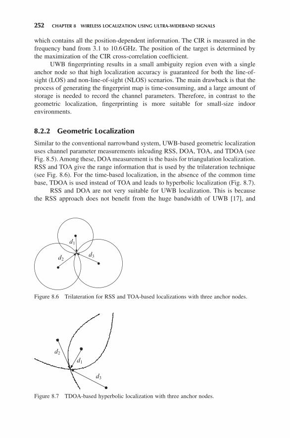
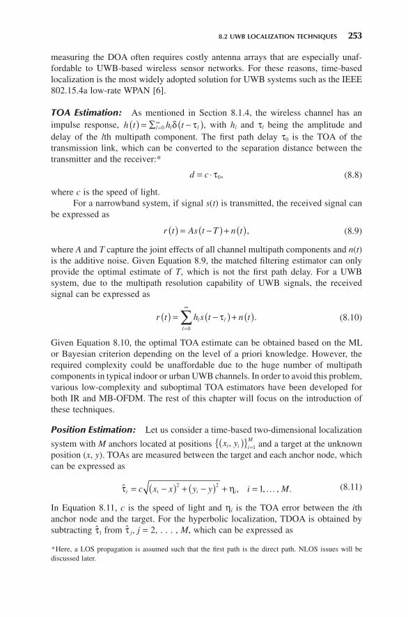
Similar to the conventional narrowband system, UWB - based geometric localization uses channel parameter measurements inlcuding RSS, DOA, TOA, and TDOA (see Fig. 8.5 ). Among these, DOA measurement is the basis for triangulation localization. RSS and TOA give the range information that is used by the trilateration technique (see Fig. 8.6 ). For the time - based localization, in the absence of the common time base, TDOA is used instead of TOA and leads to hyperbolic localization (Fig. 8.7 ).
RSS and DOA are not very suitable for UWB localization. This is because the RSS approach does not benefi t from the huge bandwidth of UWB [17] , and
Figure 8.6 Trilateration for RSS and TOA - based localizations with three anchor nodes.
d1
d2d3
Figure 8.7 TDOA - based hyperbolic localization with three anchor nodes.
measuring the DOA often requires costly antenna arrays that are especially unaf-fordable to UWB - based wireless sensor networks. For these reasons, time - based localization is the most widely adopted solution for UWB systems such as the IEEE 802.15.4a low - rate WPAN [6] .
TOA Estimation: As mentioned in Section 8.1.4 , the wireless channel has animpulse response, h t h tl l l( ) = ∑ −( )=
∞0 δ τ , with h l and τ l being the amplitude and
delay of the l th multipath component. The fi rst path delay τ 0 is the TOA of the transmission link, which can be converted to the separation distance between the transmitter and the receiver: *
d c= ⋅ τ0, (8.8)
where c is the speed of light. For a narrowband system, if signal s ( t ) is transmitted, the received signal can
be expressed as
r t As t T n t( ) = −( ) + ( ), (8.9)
where A and T capture the joint effects of all channel multipath components and n ( t ) is the additive noise. Given Equation 8.9 , the matched fi ltering estimator can only provide the optimal estimate of T , which is not the fi rst path delay. For a UWB system, due to the multipath resolution capability of UWB signals, the received signal can be expressed as
r t h s t n tl l
l
( ) = −( ) + ( )=
∞
∑ τ0
. (8.10)
Given Equation 8.10 , the optimal TOA estimate can be obtained based on the ML or Bayesian criterion depending on the level of a priori knowledge. However, the required complexity could be unaffordable due to the huge number of multipath components in typical indoor or urban UWB channels. In order to avoid this problem, various low - complexity and suboptimal TOA estimators have been developed for both IR and MB - OFDM. The rest of this chapter will focus on the introduction of these techniques.
Position Estimation: Let us consider a time - based two - dimensional localization
system with M anchors located at positions x yi i i
M,( ){ } =1 and a target at the unknown position ( x , y ). TOAs are measured between the target and each anchor node, which can be expressed as
ˆ , , .τ ηi i i ic x x y y i M= −( ) + −( ) + =2 2 , 1… (8.11)
In Equation 8.11 , c is the speed of light and η i is the TOA error between the i th anchor node and the target. For the hyperbolic localization, TDOA is obtained by subtracting ̂τ1 from ̂τ j, j = 2, . . . , M , which can be expressed as
* Here, a LOS propagation is assumed such that the fi rst path is the direct path. NLOS issues will be discussed later.
254 CHAPTER 8 WIRELESS LOCALIZATION USING ULTRA-WIDEBAND SIGNALS
ˆ ,τ η1,2 2
12
12
1 .j i i jc x x y y x x y y= −( ) + −( ) − −( ) + −( )( ) + (8.12)
As discussed in Parts I and II of this book, various techniques have been developed to estimate the target position from the TOA and TDOA measurements. The simplest way is to directly solve Equations 8.11 and 8.12 by assuming measurements are noise free [18] . The limitation of this method is that due to the measurement error, the geometric equations may not give a unique solution of the target position. This implies that the three circles in Figure 8.6 may not intersect at one point. An alterna-tive is to search for the target position that minimizes some cost functions based on Equations 8.11 and 8.12 . This is similar to the pattern matching algorithms used by the fi ngerprinting localization. If a priori knowledge of measurement errors is avail-able, the localization accuracy can be further improved by incorporating statistical criteria such as ML and Bayesian [19] . For detailed information on related tech-niques, please refer to Parts I and II of this book.
8.2.3 NLOS Issues
When signals propagate through the channel, an NLOS effect may emerge if the LOS signal component is obstructed by objects across the direct path between the transmitter and the receiver. NLOS propagation is often encountered in harsh indoor and urban environments. For time - based localization, NLOS propagation induces extra delay to the TOA measurement, which results in location estimation errors.
In the presence of NLOS, the TOA measurement relationship Equation 8.11 needs to be modifi ed accordingly. Suppose that links between the target and anchor nodes with indices i = 1, . . . , M 1 experience LOS propagation and the other M 2 = M − M 1 links undergo NLOS propagation. Then, the TOA measurement ̂τi can be expressed as
τ̂η
ηi
i i i
i i i i
c x x y y i M
c x x y y n i M=
−( ) + −( ) + =
−( ) + −( ) + + =
2 21
2 2
, 1, ,
,
…
11 1, ,.
+
⎧⎨⎪
⎩⎪ … M (8.13)
In Equation 8.13 , η i is the measurement noise and n i is the positive NLOS error of the TOA estimate.
For time - based localization, Cramer – Rao bound ( CRB ) analysis indicates that if the statistical information of NLOS errors is unknown, then only the LOS TOA estimates contribute to the location estimation of the target; if the knowledge of ni M
M{ } +1
2
1 is available, then both the LOS and NLOS TOA estimates contribute to the
location estimation [20] . These results suggest that when the statistical information of NLOS error is unknown, the NLOS TOA estimates need to be identifi ed and discarded before position estimation. However, with the knowledge of NLOS sta-tistics, the NLOS TOA estimates also provide useful information for position estima-tion. Based on these, various NLOS identifi cation and mitigation algorithms have been developed in the literature. For further details on NLOS - related techniques, please refer to Part IV of this book and survey papers [21, 22] .
In this section, we will introduce TOA estimation techniques for IR UWB that have been reported in the literature (see Table 8.1 ). As shown in Figure 8.5 , three typical TOA estimators will be covered in detail, including the ML TOA estimator, the energy detection - based TOA estimator, and the timing with dirty templates (TDT) technique. All techniques in Table 8.1 will be reviewed and compared at the end of this section.
8.3.1 System Model
Before the discussion of TOA estimation techniques, we will fi rst briefl y introduce the IR system model in the following. In an IR system, each information symbol is transmitted over a T s period that consists of N f frames. During each frame of duration T f , a data modulated pulse p ( t ) with duration T p << T f is transmitted from the antenna. The transmitted signal is
v t s n p t nTT s
n
( ) = ( ) −( )=
∞
∑E0
, (8.14)
where ε is the energy per pulse, s ( n ) is the PAM information symbol, and p T ( t ) denotes the symbol - long waveform
p t c n p t nT c n TT ds f th c
n
N f
( ) = ( ) − − ( )( )=
−
∑0
1
. (8.15)
In Equation 8.15 , c th ( n ) and c ds ( n ) are the TH and DS codes, respectively. An example of the transmitted signal with TH and DS codes is shown in Figure
8.8 . The TH and DS codes randomize the spectrum of the transmitted signal to avoid strong spectral spikes. In addition, they can be used to separate users in a multiaccess UWB system. For low - rate applications, the frame duration T f and TH codes are usually set to avoid both interframe interference ( IFI ) and intersymbol interference ( ISI ).
The transmitted signal propagates through the multipath channel with impulse
response h t h tlL
l l( ) = ∑ −( )=−01 δ τ with h = [ h 0 , h 1 , . . . , h L − 1 ] T and τ = [ τ 0 , τ 1 , . . . ,
τ L − 1 ] T being amplitudes and delays of the L multipath components, respectively. The received waveform is thus given by
256 CHAPTER 8 WIRELESS LOCALIZATION USING ULTRA-WIDEBAND SIGNALS
TABLE 8.1. TOA Estimation Algorithms for IR UWB
Reference Method Type Comments
23 Estimate delays and amplitudes of all multipath components. Use the estimated delay of the fi rst path as TOA estimate.
Maximum likelihood (ML)
Optimal estimation can be potentially achieved. Complexity can be reduced by decoupling the joint estimation to individual paths.
24 Estimate the TOA from Nyquist rate samples of the signal. Reduce the search range of each path delay by ignoring detected paths.
Generalized maximum likelihood (GML)
Reduce the complexity of the ML TOA estimator. Complexity is still high due to the Nyquist rate sampling of the received signal.
25 Estimate all taps of the sampled channel. Use the fi rst tap delay as TOA estimate.
ML The computational complexity of the ML estimator is reduced at the price of limited accuracy due to sub - Nyquist sampling.
28 Use the energy samples of the received signal. Estimate TOA with an adaptively selected threshold.
Energy detection (ED)
The complexity of the receiver is reduced with ED. The threshold is adaptively selected. Accuracy is limited by the sampling rate.
27 Threshold - based TOA estimator with matched fi ltering and squaring operations on the received signal
Threshold crossing
TOA estimation performance is limited by the sampling rate. Compared to the ED - based estimator, this TOA estimator is more effective in mitigating noise.
50 Estimate the TOA in two steps: coarse timing with low - rate energy samples and fi ne timing with higher - rate sampling.
ED, correlation
Low complexity is maintained by the low sampling rate in coarse timing. High timing accuracy is obtained by fi ne timing with higher - rate sampling.
29 Correlate adjacent symbol - long signal segments. Estimate TOA at the peak of the cross correlation.
Timing with dirty templates (TDT)
TOA estimation can be carried out in both data - aided and non - data - aided modes. The required analog delay line can be avoided by the digital receiver with low - resolution ADCs. Timing ambiguity exists due to the plateau of objective function.
30 TOA estimation with a pair of orthogonal UWB pulses.
TDT Non - data - aided timing performance is improved with the increased complexity of transceivers.
The ML algorithm estimates not only the TOA τ 0 but also the nuisance parameters
τl ll L{ } == −
11 and hl l
l L{ } == −
01. Suppose that the TH and DS codes have been synchronized
and s ( n )s are training symbols known at the receiver. The received signal segment captured in duration [0, T ] is used for TOA estimation. The ML criterion fi nds the
estimates of the channel parameters ˆ ˆ ˆ ˆh h h hL
is minimized between the received signal r ( t ) and its reconstructed version
ˆ ˆ ˆ ,r t s n h p t nTn
l T s l
l
L
( ) = ( ) − −( )=
∞
=
−
∑ ∑E0 0
1
τ (8.18)
where p T ( t ) is the symbol level transmit pulse shaper defi ned in Equation 8.15 . Based on this criterion, the ML estimates of τ and h can be obtained as (see
Reference 23 )
ˆ argmaxττ
= ( ) ( ) ( ){ }−c t t c tH R 1 (8.19)
and
ˆ ˆ ˆ ,h R= ( ) ( )−1 t c t (8.20)
where R ( τ ) is the matrix with each element being the correlation of p T ( t ) at different lags of τ :
R t( ) =
−( )−( )
−( )
⎡
⎣
⎢⎢⎢⎢
⎤
⎦
⎥⎥⎥⎥
−( )
−
∫p t
p t
p t
p t p
T
T
T L
T
T T
ττ
τ
τ
0
1
1
0
0 ,�
tt p t dtT L−( ) −( )[ ]−τ τ1 1, ,… , (8.21)
Figure 8.8 Transmitted signals for IR with TH and DS codes. In this example, the TH codes are {0, 1, 2, 1, 0} and the DS codes are {1, − 1, 1, 1, − 1}.
258 CHAPTER 8 WIRELESS LOCALIZATION USING ULTRA-WIDEBAND SIGNALS
and χ ( τ ) is the correlation between the received signal r ( t ) and p T ( t ):
c τ( ) = ( )
−( )−( )
−( )
⎡
⎣
⎢⎢⎢⎢
⎤
⎦
⎥⎥⎥⎥
−
∫ r t
p t
p t
p t
dt
T
T
T L
T
ττ
τ
0
1
1
0
.�
(8.22)
The ML estimator is too computationally intensive to be feasible due to the huge number of multipath components of the UWB channel. In Reference 23 , a simplifi ed method is adopted by assuming that multipath components are resolvable so that the joint estimation of all parameters is decoupled to individual paths. In Reference 24 , the generalized maximum likelihood ( GML ) estimator reduces the searching region of path delays by ignoring already detected paths. The complexity of the ML criterion is further reduced if the estimation is based on the sampled channel [25] .
8.3.3 Energy Detection - Based TOA Estimation
The energy detection - based TOA estimator adopts sub - Nyquist rate sampling of the received signal [26] . Compared to the ML TOA estimator, which usually requires Nyquist rate sampling, this estimator can considerably reduce the computational complexity. This estimator works for the low duty cycle modulation where no IFI is present in the received waveform. It also requires synchronized TH codes at the receiver to allow for TOA estimation.
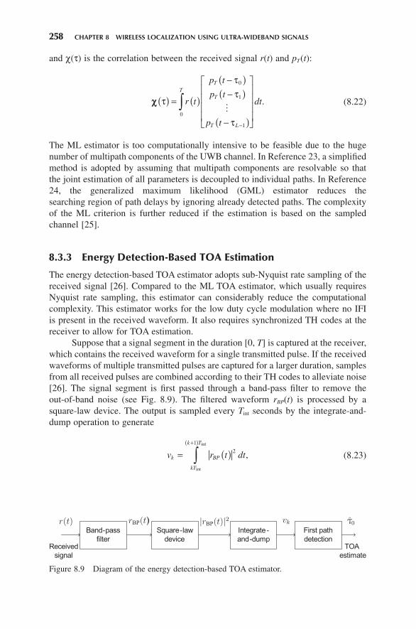
Suppose that a signal segment in the duration [0, T ] is captured at the receiver, which contains the received waveform for a single transmitted pulse. If the received waveforms of multiple transmitted pulses are captured for a larger duration, samples from all received pulses are combined according to their TH codes to alleviate noise [26] . The signal segment is fi rst passed through a band - pass fi lter to remove the out - of - band noise (see Fig. 8.9 ). The fi ltered waveform r BP ( t ) is processed by a square - law device. The output is sampled every T int seconds by the integrate - and - dump operation to generate
v r t dtk BP
kT
k T
= ( )+( )
∫ 2
1
int
int
, (8.23)
Figure 8.9 Diagram of the energy detection - based TOA estimator.
where k = 0, . . . , K − 1 with K = ⎣ T / T int ⎦ . The true TOA τ 0 is contained in the N T thτ τ0 0= ⎢⎣ ⎥⎦int sample, and samples v k , 0 10≤ ≤ −k Nτ only contain noise.
Sampling of the received signal can also be carried out by the matched fi lter receiver [27] . If the received UWB pulse p r ( t ) is known, the sampled signal sequence can be expressed as
v r t p t kT dtk BP r= .2
( ) −( )( )∫ int (8.24)
In Equation 8.24 , the squaring operation is used to remove the random polarity of the signal. Compared to Equation 8.23 , the matched fi lter receiver is more effective in mitigating the noise contained in r BP ( t ) but less effective in collecting energy especially when the sampling rate is low [19] .
These samples of the signal are fed to the fi rst path detection module. The simplest way is to estimate the TOA by picking out the sample that contains the strongest energy (see Fig. 8.10 ):
ˆ argmaxn vpk K
k= { }∈ −[ ]0, , 1
.…
(8.25)
As a result, the TOA estimate is given by
ˆ ˆτ01
2.= +n T Tp int int (8.26)
TOA estimation by fi nding the peak as Equation 8.25 is not accurate because the fi rst path is not necessarily the strongest one. A more accurate method is the threshold - based estimator where the TOA estimate is determined by fi nding the fi rst path that exceeds the threshold [26, 28] . The resolution of the energy detection - based TOA estimator is T int , which resulted from the sub - Nyquist sampling. In order to improve resolution, Gezici and Poor [17] proposed a two - step TOA estimator wherein a rough TOA estimate is fi rst obtained by the energy detection estimator and then the rough estimate is refi ned with higher - rate sampling.
Figure 8.10 Illustration of the energy detection - based TOA estimator for IR. ̂ ,τ0 1 and ̂ ,τ0 2 are TOA estimates based on the detection of the sample with the strongest energy and the fi rst crossing of the threshold.
260 CHAPTER 8 WIRELESS LOCALIZATION USING ULTRA-WIDEBAND SIGNALS
8.3.4 TDT
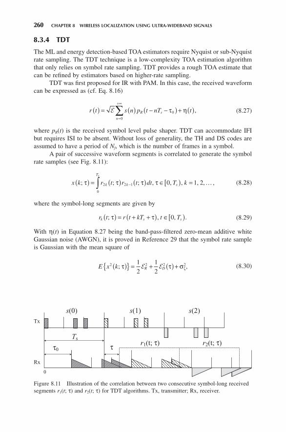
The ML and energy detection - based TOA estimators require Nyquist or sub - Nyquist rate sampling. The TDT technique is a low - complexity TOA estimation algorithm that only relies on symbol rate sampling. TDT provides a rough TOA estimate that can be refi ned by estimators based on higher - rate sampling.
TDT was fi rst proposed for IR with PAM. In this case, the received waveform can be expressed as (cf. Eq. 8.16 )
r t s n p t nT tR s
n
( ) = ( ) − −( ) + ( )=
+∞
∑E τ η0
0
, (8.27)
where p R ( t ) is the received symbol level pulse shaper. TDT can accommodate IFI but requires ISI to be absent. Without loss of generality, the TH and DS codes are assumed to have a period of N f , which is the number of frames in a symbol.
A pair of successive waveform segments is correlated to generate the symbol rate samples (see Fig. 8.11 ):
x k r t r t dt T kk k
T
s
s
; ; ,τ τ τ τ( ) = ( ) ( ) ∈[ ) =−∫ 2 2 1
0
; , 0, , 1, 2,… (8.28)
where the symbol - long segments are given by
r t r t kT t Tk s s; τ τ( ) = + +( ) ∈[ ), 0, . (8.29)
With η ( t ) in Equation 8.27 being the band - pass - fi ltered zero - mean additive white Gaussian noise ( AWGN ), it is proved in Reference 29 that the symbol rate sample is Gaussian with the mean square of
E x k R D2 2 2 21
2
1
2; ,τ τ σζ( ){ } = + ( ) +E E (8.30)
Figure 8.11 Illustration of the correlation between two consecutive symbol - long received segments r 1 ( t ; τ ) and r 2 ( t ; τ ) for TDT algorithms. Tx, transmitter; Rx, receiver.
where ε D ( τ ) = ε A ( τ ) − ε B ( τ ) and ε R is the constant energy of p R ( t ). ε D ( τ ) reaches its maximum at the correct timing point where ε A ( τ ) = 0 and ε B ( τ ) = ε R . This proves that, in the presence of the AWGN, the mean square of the symbol rate samples x ( k ; τ ) is maximized when correct timing is achieved.
The ensemble mean (Eq. 8.30 ) is replaced in practice by its sample mean
obtained from K pairs of symbol - long received segments K x kkK−=∑ ( )1
12 ; τ . This
results in the TDT algorithm that the TOA estimate can be obtained as
ˆ argmax ; ,τ τ0,
0,nda
t Ts
nday K= ( ){ }∈[ ) (8.31)
where y nda ( K ; τ ) is the objective function
y KK
r t r t dtnda k k
T
k
K s
; ; ; ,τ τ τ( ) = ( ) ( )⎛
⎝⎜
⎞
⎠⎟−
=∫∑1
2 2 1
0
2
1
(8.32)
which is the sample mean form of the ensemble expression in Equation 8.30 . This TOA estimator is non - data - aided ( NDA ) since no training sequence is required.
The number of samples K required for reliable TOA estimation can be reduced considerably in the data - aided ( DA ) mode with the training sequence s ( n ) compris-ing a repeated pattern [1, 1, − 1, − 1]. Using this sequence, the objective function can still be formulated using Equation 8.32 . With the training sequence, orders of the averaging and squaring operations can be exchanged to obtain better estimates of the mean square of x ( k ; τ ) in Equation 8.30 . Based on these, the following objective functions can be formed for the DA TDT:
y KK
r t r t dt
y K
da k k
T
k
K
da
s
1 2 2 1
0
2
1
2
1; ; ; ,
;
τ τ τ
τ
( ) = ( ) ( )⎛
⎝⎜
⎞
⎠⎟
( )
−=∫∑
== ( ) ( )⎛
⎝⎜
⎞
⎠⎟
( ) = +( )
−=∫∑1
2 2 1
01
2
3
Kr t r t dt
y K r t r
k k
T
k
K
da
s
; ; ,
;
τ τ
τ τ tt T dts
Ts
+ −( )⎛
⎝⎜
⎞
⎠⎟∫ τ
0
2
,
(8.33)
where
r tK
r t kTks
k
K
( ) = −( ) +( )=∑1
1 2 .1
The TOA estimate can be obtained with these objective functions, respectively, by
262 CHAPTER 8 WIRELESS LOCALIZATION USING ULTRA-WIDEBAND SIGNALS
Analysis in Reference 29 shows that the DA TDT outperforms the NDA TDT. In addition, even with the same training pattern, the DA estimators can have a different performance with slightly different objective functions. In Figure 8.12 , the NDA and three DA TDT algorithms are simulated to obtain the mean square error ( MSE ) of the TOA estimate normalized by Ts
2. Simulation is performed in the IEEE 802.15.3a LOS channel with the transmission distance less than 4 m. The UWB pulse is the second derivative of the Gaussian function with unit energy and duration T p ≈ 1 ns. One symbol contains N f = 32 frames each with duration T f = 32 ns. A random TH code uniformly distributed over [0, N c − 1] is adopted, with N c = 35 and T c = 1 ns. Frame - level coarse timing is performed; that is, N i = N f . K = 8 symbol rate samples are used to obtain one TOA estimate. Simulation resolutions show that DA TDTs outperform the NDA TDT. Among the three DA TDT algorithms, the one based on y da 3 ( K ; τ ) in Equation 8.33 achieves the best performance.
8.3.5 Discussions on IR - Based TOA Estimation
The ML TOA estimator [23] estimates the amplitudes and delays of all multipath components. The estimate of the fi rst path delay τ 0 automatically becomes the TOA estimate. It is the optimal one when no channel statistical information is known at the receiver. When channel statistics are known, the Bayesian estimator provides the optimal estimate. Complexity of these optimal estimators is too high because a large number of unknown parameters need to be jointly estimated. A simplifi ed version of the ML TOA estimator [23] is the GML TOA estimator [24] . The GML estimator searches the direct path in a narrowed range by ignoring the already detected paths
Figure 8.12 The MSE of the TOA estimate normalized by Ts2 as a function of the SNR.
so that the complexity of TOA estimation is reduced. The disadvantage of the GML estimator is that the required Nyquist rate sampling is still unaffordable to many UWB applications.
In Reference 25 , the ML TOA estimator is developed based on the discrete time sampled channel. The TOA estimation process is simplifi ed because each tap delay can only come from a fi nite number of values. In Reference 28 , the low - complexity threshold - based TOA estimator is investigated based on the energy detection receiver structure. The threshold is adaptively selected according to the minimum and maximum of the energy samples of the received signal. An alternative of Reference 28 is Reference 27 , where the received signal is sampled via matched fi ltering. Then, the direct path is detected when the output signal crosses the thresh-old. For detailed discussions on various threshold selection techniques, please refer to References 19 and 26 .
Performance of these low - complexity TOA estimators ( [25, 27, 28] ) is essen-tially limited by the sampling rate of the receiver. In order to simultaneously main-tain low complexity and high timing accuracy, Gezici and Poor [17] proposed a two - step TOA estimation procedure. In the coarse timing step, a rough estimate of the TOA is obtained based on the energy detection scheme with low - rate sampling of the received signal. In the fi ne - timing step, the TOA estimate is refi ned with a higher - rate sampling of signals in a small ambiguity region.
The TDT is a low - complexity TOA estimation algorithm that relies on the symbol rate samples of the received signal [29, 31] . At the receiver, adjacent symbol - long signal segments serve as the correlation template to each other. Then, the TOA estimate is determined as the instant when the correlation reaches its maximum. The advantage is that timing estimation can be achieved without any knowledge of the CIR. These estimators are suitable for obtaining coarse timing, which can be further refi ned by applying fi ne TOA estimation techniques in a much reduced ambiguity region.
The application of TDT is not limited to the single PAM UWB with analog receivers. It has been proved in Reference 31 that TDT is operational for IR with PPM. In Reference 32 , TDT is applied to the digital IR receiver with extremely low - resolution analog - to - digital converter s ( ADC s). In Reference 30 , the TDT TOA estimator is established for IR with the PSM. By adopting a pair of orthogonal pulses, the timing performance can be improved even if no training symbols are transmitted.
8.4 TOA ESTIMATION FOR MB - OFDM UWB
In this section, various TOA estimation techniques will be reviewed for the MB - OFDM UWB system (see Table 8.2 ). As shown in Figure 8.5 , three typical methods will be covered in detail including the correlation - based TOA estimator, energy detection - based TOA estimation, and TOA estimation by mitigating energy leakage. All techniques in Table 8.2 will be introduced and compared at the end of this section.
Figure 8.13 Illustration of the modulation and demodulation of MB - OFDM signals. IFFT, inverse fast Fourier transform.
Constellation Mapping
Bits
IFFT CPInsertion
DAC
(a)
ADCCoarse Sync
CPRemoval
FFTTOA
Estimation
EqualizationDecisionTime–Frequency Code
(b)
exp
exp
Time–Frequency Code
π
π
8.4.1 System Model
MB - OFDM combines the basic OFDM technique with the frequency hopping tech-nique. Within each symbol duration, a signal block is transmitted in two steps. First, the baseband signal is generated in the same manner as the traditional single - band OFDM system. Then, the baseband signal is upconverted to the center frequency of a sub - band according to some predefi ned TF hopping pattern and is transmitted from the antenna. In the ECMA MB - OFDM UWB, each user can access up to three sub - bands each having a bandwidth of 528 MHz [4] .
Figure 8.13 shows the transmitter and receiver diagrams of the MB - OFDM system. For an MB - OFDM system with B frequency sub - bands, a block of informa-tion symbols s b = [ s b ,1 , . . . , s b , K ] T is multicarrier modulated to the b th frequency band, b ∈ [1, B ] on K orthogonal digital subcarriers to form the signal block
x F sb b= H , (8.35)
where F is the K × K discrete Fourier transform ( DFT ) matrix. A cyclic prefi x ( CP ) is added to each block to mitigate the interblock interference ( IBI ) induced by the multipath channel. After digital - to - analog conversion ( DAC ), the signal is carrier modulated and transmitted from the antenna. The transmitted signal then propagates through the channel.
At the receiver, the arriving waveform is carrier demodulated, sampled, and digitalized by the ADC to obtain baseband discrete time samples. After the symbol
266 CHAPTER 8 WIRELESS LOCALIZATION USING ULTRA-WIDEBAND SIGNALS
level coarse timing, the CP is removed and the baseband signal is multicarrier demodulated with fast Fourier transform ( FFT ) to generate frequency domain signals
vb k k
K,{ } =1. It can be readily shown that
v s H k K b Bb k b k b k b k, , , , , 1 , , 1 ,= + = =ξ , , ,… … (8.36)
where ξ b , k is the noise and H b , k is the Fourier transform ( FT ) coeffi cient of the CIR:
H h jb k l
l
L
b k l, ,exp ,= ⋅ −( )=
−
∑0
1
ω τ (8.37)
where ω b , k is the frequency of the k th subcarrier on the b th frequency band. Based on Equation 8.36 , the estimate of the frequency domain channel H b , k
can be easily formed as
ˆ ,Hv
sH k K b Bb k
b k
b kb k b k,
,
,, , , 1, , , 1, ,= = + = =η … … (8.38)
where η b , k = ξ b , k / s b , k is the noise term on the ( b , k )th subcarrier (see Reference 33 ). For the channel estimation - based TOA estimator, the CIR will be reconstructed from H b , k by various algorithms based on the basic idea of the inverse Fourier transform.
8.4.2 Correlation - Based TOA Estimator
The correlation - based TOA estimator provides coarse timing synchronization for OFDM signals [34, 35] . It estimates the channel TOA by exploiting the periodicity of OFDM signals due to the transmission of CP or training symbols. The complexity of this technique is low because CIR does not need to be reconstructed. After the coarse synchronization provided by these algorithms, accuracy of the rough TOA estimate can be improved by fi ne timing estimation algorithms.
A simple way of performing the correlation - based TOA estimation is to trans-mit the training symbol with two identical halves in the time domain [35] . This can be realized by modulating an N /2 - long pseudonoise ( PN ) sequence on even subcar-riers and N /2 zeros on odd subcarriers, with N being an even integer. The PN sequence guarantees that the time domain correlation function of the half symbol has a sharp peak. After propagating through the same wireless channel, the received signals corresponding to these two halves are identical except for a phase rotation induced by the carrier frequency offset.
At the receiver, the cross - correlation function is calculated for the b th sub - band between two successive half - symbol - long received signal segments each of N /2 samples at the candidate time shift d :
where r b , n is the n th sample of the received signal in the b th sub - band. The timing metric is then defi ned as
MP
Rb d
b d
b d
,,
2
,2
=( )
, (8.40)
where R b , d is the received energy for the second half symbol involved in the TOA estimation
R rb dd n
N
n
N
,
2
2
0
21
.=+ +
=
−
∑ (8.41)
This timing metric shows a plateau with the width being the length of the CP minus the length of the CIR. Any candidate time shift selected inside the plateau can be used as the rough TOA estimate, which will induce no IBI and therefore cause no degradation of the symbol error rate ( SER ) performance.
Based on the correlation obtained for each sub - band, the TOA can be estimated at the k th sample instant
k Pd
b d
b
B
==∑argmax ,
1
. (8.42)
Timing accuracy of the basic correlation - based TOA estimator can be improved using multiple training symbols so that the timing metric will show a sharp trajec-tory. In Reference 36 , the periodicity due to CP is also exploited for TOA estimation to reduce the overhead by transmitting training symbols.
8.4.3 Energy Detection - Based TOA Estimator
After coarse timing synchronization, the TOA estimation accuracy can be improved by fi ne timing algorithms that require reconstruction of the CIR. Basically, the same fi ne - timing algorithms for IR can be applied to MB - OFDM with slight modifi ca-tions, after CIR is reconstructed. For example, the ML criterion can be used to jointly estimate the delays and amplitudes of all multipaths as well as other nuisance param-eters. Then, the delay estimate of the fi rst path becomes the TOA estimate [37] . For the purpose of low - complexity estimation, the CIR can be sampled as the equally spaced sequence in a similar manner as the energy detection - based TOA estimator and the matched fi ltering TOA estimator for IR.
Let r b , n denote the baseband received signal from the b th sub - band and sb n n
N,{ } =
−01
the transmitted synchronization sequence. The sampled channel is obtained by the matched fi ltering operation [38]
268 CHAPTER 8 WIRELESS LOCALIZATION USING ULTRA-WIDEBAND SIGNALS
Sampling of the channel can also be carried out by fi tting the frequency domain channel information to an equally spaced sequence [39] . In order to distinguish the estimated channel from the physical channel, in the rest of this section, the term “ tap ” is used for samples in the estimated CIR and “ path ” for arriving rays in the original physical channel.
In Reference 34 , fi ne timing is achieved by fi nding the fi rst segment of K samples with energy exceeding a threshold. Both K and the threshold depend on the channel environment. A similar method exists for IR, which is known as the p − max technique [26] . In Reference 40 , a joint channel order and TOA estimation technique based on the Akaike information, which is proposed for single - band OFDM, can be readily extended to the multiband case. Next, the energy detection - based TOA esti-mator will be presented as an example to show how the single - band algorithms can be extended to the multiband system.
For the energy detection - based TOA estimator, it is assumed that the CIR has been sampled into discrete taps for all B sub - bands. L taps of the sampled channel contain channel information. The n th tap of the sampled channel for the b th sub - band can be expressed as follows:
hh n L L L
n L n L L Lb n
b n L b n
b n,
, 1 , 1 1
, 1 1 1
, , 1
, 0, 1 ,=
+ ∈ + −[ ]∈ −[ ] ∈ +
− ηη and ++ + −[ ]
⎧⎨⎩
∈[ ]L L
b B2 1
1,, , (8.44)
where h b , n are noise - free samples of the CIR; L 1 and L 2 represent the ambiguity of coarse timing.
After the channel is sampled, the energy detection criterion is adopted for TOA estimation. In particular, for a single band, this estimator detects the starting point of the channel by seeking the maximum total energy of a length L segment in the channel estimate sequence given by Equation 8.44 . With the availability of multiple sub - bands, this TOA estimator simply combines the energy from all sub - bands via noncoherent combining. Then, the index of the fi rst channel tap can be estimated as
k hp
b n
n p
p L
b
B
=⎛
⎝⎜
⎞
⎠⎟
=
+ −
=∑∑argmax ,
21
1
. (8.45)
Figure 8.14 shows the probability of mistiming curves for the energy detection - based TOA estimator. In the simulation, the sampled channel has L = 12 independent Nakagami - m distributed channel taps and L 1 = L 2 = 5 pure noise terms. The channel has an exponentially decaying PDP with the last tap being 20 dB weaker than the fi rst tap. It is proved in Reference 41 that the energy detection - based TOA estimation can achieve a diversity gain of mB . This implies that by the noncoherent combining, the energy detection - based TOA algorithm can achieve a higher diversity gain, which is proportional to the number of sub - bands and the channel diversity.
Example 8.2
Use the codes in Chapter_8_Example_2.m to simulate the mistiming probability for the energy detection - based TOA estimator. MATLAB codes can be found online at ftp://ftp.wiley.com/public/sci_tech_med/matlab_codes . The channel has indepen-
Figure 8.14 Probability of mistiming as a function of SNR for the energy detection - based TOA estimator.
0 5 10 15 20 25 3010
−4
10−3
10−2
10−1
100
101
SNR (dB)
Pro
babi
lity
of m
istim
ing
B = 6, m = 1B = 3, m = 2B = 2, m = 3B = 1, m = 6Union bounds
dent Nakagami - m distributed samples. Try different values of the Nakagami - m parameter and the number of sub - bands. Confi rm that the same diversity gain can be acquired for a fi xed mB .
Solution
The channel has taps with Nakagami - m distributed envelopes and uniformly distrib-uted phases. Note that Nakagami - m random variables are generated by Matlab function gamrnd() by using the relationship between the Nakagami - m distribution and the gamma distribution. In particular, if the distribution of random variable X is Nakagami( m , Ω ) with m = E 2 [ X 2 ]/Var[ X 2 ] and Ω = E [ X 2 ], Y = X 2 can be generated by the distribution Y ∼ gamma( m , Ω / m ).
8.4.4 TOA Estimation by Suppressing Energy Leakage
Channel estimation by sampling the CIR results in the energy leakage phenomenon that has been ignored in many TOA estimation algorithms for OFDM and MB - OFDM. Energy leakage means that the energy of one channel path disperses into all taps in the sampled CIR when this path is missampled (see Fig. 8.15 ). The coun-terpart of energy leakage in IR is the interpath interference ( IPI ). Energy leakage needs to be mitigated because it induces TOA estimation error. Based on this, a TOA estimation criterion that simultaneously suppresses the energy leakage is proposed in References 39 and 42 .
The channel can be estimated by sampling the CIR at intervals of T p by
L T Th p= ⎡⎢ ⎤⎥ taps each with amplitude and delay hn and τ τn pnT= +0 , 0 1≤ ≤ −n L , respectively, with T h being the maximum channel delay spread. For every possible
270 CHAPTER 8 WIRELESS LOCALIZATION USING ULTRA-WIDEBAND SIGNALS
fi rst tap delay τ0, the sampling is performed by assuming that the tap amplitudes hl τ1( ) satisfy (cf. Eq. 8.37 )
h j H k K b Bn b k n
n
L
b kτ ω τ0 ,
0
1
,exp , , , , , , ,( ) −( ) = = ==
−
∑ ˆ 1 1… … (8.46)
where the dependence of h sn on τ0 is explicitly shown. The tap interval T p is set as the inverse of the signal bandwidth, which is known as the time domain resolution of the system [43] . When T p is smaller than the system resolution, the sampling equation tends to be ill - conditioned and unsolvable [39] .
When training data are constant modulus over subcarriers, channel estimation of Equation 8.46 is equivalent to the time domain sampling based on matched fi lter-ing (see Eq. 8.43 ). The difference is that Equation 8.46 can adopt the coherent combining of multiband channel information that does not directly apply to the time domain matched fi ltering. Besides, Equation 8.46 is a more fl exible channel estima-tor due to the free parameter τ0.
Let h ln τ0,( ) denote the contribution from the l th channel path at the n th tap
so that h h ln lL
n nτ τ η τ0 01
0 0( ) = ∑ ( ) + ( )=− , with η τn 0( ) being the noise. It turns out that
h l hj N
NT
T
Nn l
n l
p
n l pτπ τ τ π τ τ
π τ0
1, exp
sin
sin( ) = −( ) −( )⎛
⎝⎜⎞⎠⎟
−( )( )nn l pNT−( ) ( )( )τ
(8.47)
has the form of the discrete sinc function sin( π t / T p )/( N sin( π t /( NT p ))) sampled at t n l= −( )τ τ , n L∈ −[ ]0 1, (see Fig. 8.15 ). For multipath channels, energy leakage is
Figure 8.15 Illustration of the energy leakage h lτ0,( ) from the l th channel path when missampling occurs.
Figure 8.16 Illustration of the energy leakage prior to the fi rst arriving path with two different values of the fi rst tap delay τ0.
(a)
(b)
–0.2
–0.4
–0.2
–0.4
always present because the equally spaced sequence cannot exactly sample all paths. In this case, the IPI due to energy leakage becomes the main source of error for TOA estimation.
TOA can be estimated when energy leakage prior to TOA is minimized in the sampled channel so that a sharp jump of amplitude shows up around the leading path (Fig. 8.16 b). This is in contrast to Figure 8.16 a, where strong energy leakage disperses before the channel TOA. The sharp jump of amplitude can be detected by searching the value of τ0 that maximizes the following energy ratio between two adjacent taps of the sampled CIR:
γ ττ
τn
n
n
h
hn L L0
02
1 02 1 2, ,( ) = ( )
( )∈[ ]
−
, (8.48)
where [ L 1 , L 2 ] represents the ambiguity region of the fi rst channel path after coarse timing synchronization. The TOA estimate τ 0 is then obtained as the delay of the tap where Equation 8.48 is maximized:
272 CHAPTER 8 WIRELESS LOCALIZATION USING ULTRA-WIDEBAND SIGNALS
ˆ ˆ ˆτ τ0 0= + nTp (8.49)
with
ˆ , ˆ argmaxτ γ τ
τ0
0 ,0
0 1 2
.nT L n L
nh
( ) = ( )≤ < ≤ ≤
(8.50)
In Reference 39 , the relationship between γ τn 0( ) and the TOA estimation error is analyzed. Analysis shows that the time estimation error is reduced when the interference from trailing paths decreases due to either weaker trailing paths or larger time separation between the fi rst path and the trailing ones.
In References 39 and 42 , the following modifi ed energy ratio is shown to be a better measure than the one in Equation 8.48 :
γ τ
τ
τn
n
i
i n
n MM
h
Mh
n L L00
2
02
1
1 21
, , .,( ) = ( )
( )∈[ ]
= −
−
∑ (8.51)
This modifi ed form avoids the energy ratio γ τn 0( ) from being maximized at taps that contain strong energy from the trailing paths.
The TOA estimator is tested in all eight IEEE 802.15.4a channel models, as shown in Figure 8.17 . Simulations are performed using the ECMA MB - OFDM system parameters with the fi rst three sub - bands and M = 5. Performance in the LOS channel is generally better than that in the corresponding NLOS channel. This is
Figure 8.17 The mean absolute TOA estimation error as a function of the SNR.
because in the NLOS channel, the fi rst path may not be strong and the estimator is more affected by the trailing paths. However, there is an exception for the outdoor environment at high signal - to - noise ratio (SNR) values. From their channel realiza-tions, it can be found that channel paths in the NLOS outdoor channel are weaker but sparser than the LOS outdoor channel. As a result, the NLOS outdoor channel can be even better resolved than the LOS outdoor channel, and therefore the deter-mination of its fi rst path will be less interfered by the trailing paths.
8.4.5 Discussions on MB - OFDM - Based TOA Estimation
In Reference 35 , the timing estimation of OFDM signals is carried out by correlating the received signal of the transmitted training sequence with two identical halves. The TOA estimate is obtained at the time instant when the correlation coeffi cient reaches its maximum. Due to the protection of CP, the signal component of the cor-relation shows a plateau, which corresponds to the ISI free part of CP. This implies that any timing synchronization point selected inside this range induces no ISI. This correlation - based method provides low - complexity coarse TOA estimation for single - band OFDM. For MB - OFDM, it can be readily implemented if the overall correlation is obtained by summing up sub - band correlations [44] .
In Reference 34 , an enhanced version of Reference 35 is presented, which uses multiple training OFDM symbols with their polarities determined by the training symbol pattern. If the training symbol pattern is properly chosen, the correlation has a sharp trajectory so that the resilience against noise is improved. Simulation results in Reference 34 show that this estimator outperforms those in Reference 35 at low SNR values. Timing performance of Reference 34 is comparable to that of Reference 35 . In References 36 and 45 , timing of OFDM signals is achieved by exploiting the redundancy introduced by CP. An advantage of this CP - based technique is high spectral effi ciency. The drawback is that, since the CP part of the received symbol also contains ISI, performance of this estimator degrades drastically when the mul-tipath channel becomes more dispersive.
The correlation - based TOA estimators are low complexity because the correla-tion function can be iteratively calculated. However, these estimators cannot provide fi ne TOA estimates due to the timing ambiguity induced by the correlation plateau. In order to obtain a fi ne TOA estimate, the estimator needs to resolve the multipath components from the received signal, which results in the channel estimation - based TOA estimator. For OFDM, channel estimation can be carried out by matched fi lter-ing [38, 46] or by converting the frequency domain channel information into the time domain [39, 47] . After channel estimation, the TOA estimate can be determined by detecting the leading edge.
In References 38 and 46 , matched fi ltering is adopted to sample the received signal with the transmitted training sequence. Output of the matched fi lter is the sample spaced discrete time channel. This is the same as the matched fi ltering TOA estimation for IR UWB (e.g., see Reference 26 ). Therefore, various fi rst path detec-tion algorithms developed for IR can be applied to MB - OFDM with slight modifi ca-tion (e.g., see References 26 and 28 ). Depending on the level of a priori knowledge, TOA can be estimated by several means, such as using the strongest sample of the
274 CHAPTER 8 WIRELESS LOCALIZATION USING ULTRA-WIDEBAND SIGNALS
sampled channel [46] , fi nding the fi rst signifi cant path energy that exceeds a thresh-old, searching for the segment of L samples with the strongest total energy with L being the length of the sample spaced channel [41] , and fi nding the strongest total energy of the segment weighted by the channel PDP [19] . Similar to the IR system, performance of these MB - OFDM TOA estimators is limited by the sampling rate. In addition, matched fi ltering TOA estimators are more computationally intensive than correlation - based TOA estimators.
An alternative means of estimating the CIR is to transform the frequency domain channel information to time domain after subcarrier demodulation. Due to the huge number of multipath components of UWB channels, the optimal ML and Bayesian channel estimators are too computationally intensive to be feasible. Therefore, research has mainly focused on the development of low - complexity channel estimators such as the GML and modifi ed GML ones, which reduce the path searching region [24, 48] , and the model - based estimator [42] by sampling the CIR with an equally spaced sequence. One major advantage of these estimators is that the multiband channel information can be coherently combined, which is not the case for the correlation - based and matched fi ltering estimators.
For coherent combining, the multiple sub - bands are treated as a single huge band, which allows the estimator to achieve the full resolution facilitated by the entire bandwidth [42, 49] . In comparison, the noncoherent combining for correlation - based and matched fi ltering estimators can only obtain the resolution facilitated by the sub - band bandwidth. Advantages of the noncoherent combining are the lower computational complexity than the coherent combining and no requirement for the estimation of the random phase rotation after carrier demodula-tion [39, 42] .
8.5 CONCLUSIONS
In this chapter, we introduced localization and TOA estimation techniques for IR and MB - OFDM UWB systems. Background knowledge of UWB is reviewed at the beginning of this chapter. Due to their huge bandwith, UWB signals can provide orders of magnitude improvement on the timing resolution compared to conven-tional narrowband signals. For this reason, this chapter has focused on the time - based localizations for UWB. In particular, various TOA estimation algorithms are reviewed, including both coarse and fi ne - timing techniques.
Depending on the way of accessing the UWB bandwidth, UWB systems can be categorized into two types, namely, IR and the MB - OFDM UWB. For IR UWB, the ML criterion was fi rst revisited, which is the optimal yet computationally demanding TOA estimation approach. In order to achieve low - complexity TOA estimation, two practical approaches were then introduced, including the energy detection - based TOA estimator and the TDT algorithms. These two approaches rely on sub - Nyquist rate and symbol rate sampling of the received signal, respectively. For the MB - OFDM UWB, the correlation - based TOA estimator was fi rst reviewed, which provides coarse timing by exploiting the periodicity of OFDM signals. After coarse timing, the rough TOA estimate can be refi ned by the channel estimation -
based TOA estimator. To this end, two fi ne - timing techniques were introduced based on energy detection and suppression of energy leakage criteria, respectively.
Some issues important for UWB and also for general wireless localization such as the NLOS mitigation and multiuser localization were not discussed in this chapter. For details on these topics, please refer to corresponding chapters of this book.
REFERENCES
[1] Federal Communications Commission , FCC First Report and Order: In the matter of Revision of Part 15 of the Commission ’ s Rules Regarding Ultra - Wideband Transmission Systems , FCC 02 - 48, April 2002 .
[2] European Commission , Draft Commission Decision on the harmonised use of radio spectrum by equipment using ultra - wideband technology in the Community , RSCOM06 - 90 Final, December 2006 .
[3] Ministry of Internal Affairs and Communications, Japan , AWF3/14, “ Technical conditions on UWB radio systems in Japan , ” 2006 .
[4] ECMA International , ECMA - 368: High rate ultra wideband PHY and MAC standard, 1st edition , December 2005 .
[5] ECMA International , ECMA - 369: MAC - PHY Interface for ECMA - 368, 1st edition , December 2006 .
[6] IEEE 802.15.4 Working Group , “ Part 15.4: Wireless medium access control (MAC) and physical layer (PHY) specifi cations for low - rate wireless personal area networks (WPANs), amendment 1: Add alternate PHYs , ” Approved: Mar. 2007 , IEEE - SA Standards Board.
[7] A. A. M. Saleh and R. A. Valenzuela , “ A statistical model for indoor multipath propagation , ” IEEE J. Sel. Area. Comm. , vol. 5 , no. 2 , pp. 128 – 137 , 1987 .
[8] A. F. Molisch , K. Balakrishnan , D. Cassioli , C. - C. Chong , S. Emami , A. Fort , J. Karedal , J. Kunisch , H. Schantz , U. Schuster , and K. Siwiak , IEEE 802.15.4a channel model — fi nal report , November 2004 .
[9] A. F. Molisch , J. R. Foerster , and M. Pendergrass , “ Channel models for ultrawideband personal area networks , ” IEEE Wireless Commun. , vol. 10 , no. 6 , pp. 14 – 21 , 2003 .
[10] R. Battiti , M. Brunato , and A. Villani , “ Statistical learning theory for location fi ngerprinting in wireless LANs , ” # DIT - 02 - 0086, Tech. Rep., 2002 .
[11] S. Gezici , H. Kobayashi , and H. Poor , “ A new approach to mobile position tracking , ” Proc. of IEEE Sarnoff Symp. Advances in Wired and Wireless Communications , pp. 204 – 207 , 2003 .
[12] M. McGuire , K. N. Plataniotis , and A. N. Venetsanopoulos , “ Location of mobile terminals using time measurements and survey points , ” IEEE Trans. Veh. Technol. , vol. 52 , no. 4 , pp. 999 – 1011 , 2003 .
[13] C. Nerguizian , C. Despins , and S. Aff è s , “ Geolocation in mines with an impulse response fi nger-printing technique and neural networks , ” Proc. of IEEE 60th Vehicular Technology Conference (VTC2004 - Fall) , 5 , 2004 , pp. 3589 – 3594 .
[14] C. Steiner and A. Wittneben , “ Low complexity location fi ngerprinting with generalized UWB energy detection receivers , ” IEEE Trans. Signal Process. , vol. 58 , no. 3 , pp. 1756 – 1767 , 2010 .
[15] C. Steiner , F. Althaus , F. Troesch , and A. Wittneben , “ Ultra - wideband geo - regioning: a novel cluster-ing and localization technique , ” EURASIP J. Adv. Signal Process. , vol. 2008 , pp. 1 – 13 , Article ID 296937, 13 pages, 2008 . doi:10.1155/2008/296937.
[16] W. Q. Malik and B. Allen , “ Wireless sensor positioning with ultrawideband fi ngerprinting , ” Proc. of First European Conference on Antennas and Propagation (EuCAP) , pp. 1 – 5 , 2006 .
[17] S. Gezici and H. V. Poor , “ Position estimation via ultra - wide - band signals , ” Proc. IEEE , vol. 97 , no. 2 , pp. 3864 – 3403 , 2009 .
[18] A. H. Sayed , A. Tarighat , and N. Khajehnouri , “ Network - based wireless location , ” IEEE Signal Process. Mag. , vol. 22 , no. 4 , pp. 24 – 40 , 2005 .
276 CHAPTER 8 WIRELESS LOCALIZATION USING ULTRA-WIDEBAND SIGNALS
[19] Z. Sahinoglu , S. Gezici , and I. Guvenc , Ultra - Wideband Positioning Systems: Theoretical Limits, Ranging Algorithms, and Protocols . New York : Cambridge University Press , 2008 .
[20] Y. Qi , H. Kobayashi , and H. Suda , “ Analysis of wireless geolocation in a non - line - of - sight environ-ment , ” IEEE Trans. Wireless Commun. , vol. 5 , no. 3 , pp. 672 – 681 , 2006 .
[21] I. Guvenc , C. - C. Chong , and F. Watanabe , “ NLOS identifi cation and mitigation for UWB localiza-tion systems , ” Proc. of Wireless Communications and Networking Conf. , pp. 1571 – 1576 , 2007 .
[22] J. Khodjaev , Y. Park , and A. S. Malik , “ Survey of NLOS identifi cation and error mitigation problems in UWB - based positioning algorithms for dense environments , ” Ann. Telecommun. , vol. 65 , no. 5 – 6 , pp. 301 – 311 , 2010 . doi:10.1007/s12243 - 009 - 0124 - z.
[23] M. Z. Win and R. A. Scholtz , “ Characterization of Ultra - Wide bandwidth wireless indoor channels: a communication - theoretic view , ” IEEE J. Sel. Area. Comm. , vol. 20 , no. 9 , pp. 1613 – 1627 , 2002 .
[24] J. Y. Lee and R. A. Scholtz , “ Ranging in a dense multipath environment using an UWB radio link , ” IEEE J. Sel. Area. Comm. , vol. 20 , no. 9 , pp. 1677 – 1683 , 2002 .
[25] Z. Tian and G. B. Giannakis , “ Data - aided ML timing acquisition in Ultra - Wideband radios , ” Proc. of IEEE Conf. on Ultra - Wideband Systems and Technologies , Reston, VA, pp. 142 – 146 , November 16 – 19, 2003 .
[26] D. Dardari , A. Conti , U. Ferner , A. Giorgetti , and M. Z. Win , “ Ranging with ultrawide bandwidth signals in multipath environments , ” Proc. IEEE , vol. 97 , no. 2 , pp. 404 – 426 , 2009 .
[27] D. Dardari , C. - C. Chong , and M. Z. Win , “ Threshold - based time - of - arrival estimators in UWB dense multipath channels , ” IEEE Trans. Commun. , vol. 56 , no. 8 , pp. 1366 – 1378 , 2008 .
[28] I. Guvenc and Z. Sahinoglu , “ Threshold - based TOA estimation for impulse radio UWB systems , ” IEEE International Conference on Ultra - Wideband , pp. 420 – 425 , 2005 .
[29] L. Yang and G. B. Giannakis , “ Timing Ultra - Wideband signals with dirty templates , ” IEEE Trans. Commun. , vol. 53 , no. 11 , pp. 1952 – 1963 , 2005 .
[30] M. Ouertani , H. Xu , L. Yang , H. Besbes , and A. Bouallegue , “ Orthogonal bi-pulse UWB: Timing and (de)modulation , ” Elsevier Phys. Commun. , vol. 1 , no. 4 , pp. 237 – 247 , 2008 .
[31] L. Yang , “ Timing PPM - UWB signals in ad hoc multi - access , ” IEEE J. Sel. Area. Comm. , vol. 24 , no. 4 , pp. 794 – 800 , 2006 .
[32] H. Xu and L. Yang , “ Timing with dirty templates for low - resolution digital UWB receivers , ” IEEE Trans. Wireless Commun. , vol. 7 , no. 1 , pp. 54 – 59 , 2008 .
[33] Z. Wang , G. Mathew , Y. Xin , and M. Tomisawa , “ An iterative channel estimator for indoor wireless OFDM systems , ” Proc. of IEEE Intl. Conf. Commun. Sys. (ICCS) , Singapore, pp. 1 – 5 , October 30 – November 1, 2006 .
[34] H. Minn , V. K. Bhargava , and K. B. Letaief , “ A robust timing and frequency synchronization for OFDM systems , ” IEEE Trans. Wireless Commun. , vol. 2 , no. 4 , pp. 799 – 807 , 2003 .
[35] T. M. Schmidl and D. C. Cox , “ Robust frequency and timing synchronization for OFDM , ” IEEE Trans. Commun. , vol. 45 , no. 12 , pp. 1613 – 1621 , 1997 .
[36] B. Yang , K. B. Letaief , R. S. Cheng , and Z. Cao , “ Timing recovery for OFDM transmission , ” IEEE J. Sel. Area. Comm. , vol. 18 , pp. 2278 – 2291 , 2000 .
[37] B. H. Fleury , M. Tschudin , R. Heddergou , D. Dahlhaus , and K. I. Pedersen , “ Channel parameters estimation in mobile radio environments using SAGE algorithm , ” IEEE J. Sel. Area. Comm. , vol. 17 , no. 3 , pp. 434 – 449 , 1999 .
[38] Z. Ye , C. Duan , P. Orlik , and J. Zhang , “ A low - complexity synchronization design for MB - OFDM ultra - wideband systems , ” Proc. of International Conf. on Communications , Beijing, China, pp. 3807 – 3813 , May 19 – 23, 2008 .
[39] H. Xu and L. Yang , “ TOA estimation for MB - OFDM UWB by suppressing energy leakage , ” Proc. of MILCOM Conf. , San Jose, CA, pp. 718 – 723 , October 31 - November 3, 2010 .
[40] E. G. Larsson , G. Liu , J. Li , and G. B. Giannakis , “ Joint symbol timing and channel estimation for OFDM based wlans , ” IEEE Commun. Lett. , vol. 5 , no. 8 , pp. 325 – 327 , 2001 .
[41] H. Xu , L. Yang , Y. T. Morton , and M. Miller , “ Mistiming performance analysis of the energy detection based toa estimator for MB - OFDM , ” IEEE Trans. Wireless Commun. , vol. 8 , no. 8 , pp. 3980 – 3984 , 2009 .
[42] H. Xu , C. - C. Chong , I. Guvenc , and L. Yang , “ High - resolution TOA estimation with multi - band OFDM UWB signals , ” Proc. of International Conf. on Communications , Beijing, China, pp. 4191 – 4196 , May 19 – 23, 2008 .
[43] O. Simeone , Y. Bar - Ness , and U. Spagnolini , “ Pilot - based channel estimation for OFDM systems by tracking the delay subspace , ” IEEE Trans. Wireless Commun. , vol. 3 , no. 1 , pp. 315 – 325 , 2004 .
[44] Y. Li , H. Minn , and R. M. A. Rajatheva , “ Synchronization, channel estimation, and equalization in MB - OFDM systems , ” IEEE Trans. Wireless Commun. , vol. 7 , no. 11 , pp. 4341 – 4352 , 2008 .
[45] J. - J. van de Beek , M. Sandell , and P. O. Borjesson , “ ML estimation of time and frequency offset in OFDM systems , ” IEEE Trans. Signal Process. , vol. 45 , no. 7 , pp. 1800 – 1805 , 1997 .
[46] C. W. Yak , Z. Lei , S. Chattong , and T. T. Tjhung , “ Timing synchronization for ultra - wideband (UWB) multi - band OFDM systems , ” Proc. of Vehicular Technology Conf. vol. 3 , Dallas, TX, pp. 1599 – 1603 , September 25 – 28, 2005 .
[47] S. Zhang and J. Zhu , “ SAGE based channel estimation and delay tracking scheme in OFDM systems , ” Proc. of Vehicular Technology Conf. , Stockholm, Sweden, pp. 788 – 791 , May 30 – June 1, 2005 .
[48] C. - D. Wann and S. - W. Yang , “ Modifi ed GML algorithm for estimation of signal arrival time in UWB systems , ” Proc. of Global Telecommunications Conf. , San Francisco, CA, Nov. 27 – Dec. 1, 2006 .
[49] E. Saberinia and A. H. Tewfi k , “ Ranging in multiband ultrawideband communication systems , ” IEEE Trans. Veh. Technol. , vol. 57 , no. 4 , pp. 2523 – 2530 , 2008 .
[50] S. Gezici , Z. Sahinoglu , A. F. Molisch , H. Kobayashi , and H. V. Poor , “ Two - step time of arrival estimation for pulse - based ultra - wideband systems , ” EURASIP J. Adv. Signal Process. , vol. 2008 , pp. 1 – 11 , Article ID 529134, 11 pages, 2008 .
[51] R. A. Saeed , S. Khatun , B. M. Ali , and M. A. Khazani , “ Performance of ultra - wideband time - of - arrival estimation enhanced with synchronization scheme , ” ECTI Trans. Electr. Eng. Eletron Commun. , vol. 4 , no. 1 , pp. 78 – 84 , 2006 .
[52] C. R. Berger , S. Zhou , Z. Tian , and P. Willett , “ Performance analysis on an MAP fi ne timing algo-rithm in UWB multiband OFDM , ” IEEE Trans. Commun. , vol. 56 , no. 10 , pp. 1606 – 1611 , 2008 .