Ultrafast analog computer circuits that use the Pockels effect
Hubert Houtman
Department of Physics, University of British Columbia, Vancouver, British Columbia V6T lZ1, Canada
Received January 6, 1993
Novel optoelectronic circuits are presented that perform the analog mathematical operations of addition, sub-traction, multiplication, temporal differentiation, and temporal integration for electrical signals that may havearbitrary frequency components in the extremely broad range of 0-100 GHz. Recent reports have demonstratedthat simple, integrated-optic Mach-Zehnder intensity modulators with an almost flat frequency response maybe constructed. The ultrafast (-3-ps rise time) cascadable circuits described here represent straightforwardextensions of this technology, and only the well-known relations for the linear, electro-optic Pockels effect arerequired, as applied to traveling-wave phase modulators.
Recent advances in low-voltage Mach-Zehnder inter-ferometer modulators" 2 and other light modulators3' 4
are remarkable; intensity modulators may be con-structed for lasers in the 300-nm to 3-,um spectralrange, over the extremely broad electrical modulationfrequency range of 0-40 GHz (Refs. 2 and 3) andeven up to -100 GHz.4 Equally remarkable are therecent advances in amplifier technology; by usingmodulation-doped field-effect transistors, 5 amplifierswith a current gain cutoff of more than 200 GHz arenow available. With such amplifiers together withthe modulators it should soon be possible to modulatelaser beams at these frequencies, using input signalsin the millivolt range and even in the microvolt range.Demodulation of these modulated optical signals (atoptical-wave carrier frequencies of 100-1000 THz) isreadily accomplished simply by using suitable ultra-fast detectors,6 which are now becoming available forthe modulation frequency range of 0-500 GHz.
In this Letter we present mathematical proof thatthis technology may be easily extended for the con-struction of extremely large-bandwidth (-100 GHz)subtracters (or differential amplifiers), adders, mul-tipliers, time differentiators, time integrators, andany combination thereof (in cascade). We assumeonly the principles describing the well-known linear,electro-optic Pockels effect.7 -9 Each interferometerarm contains one or more impedance-matched,velocity-matched, traveling-wave Pockels cells8-"1(phase modulators), suitably miniaturized, as in theconventional Mach-Zehnder modulator.1 2'8 -"1 Suchvelocity matching has been successfully accomplishedby several groUpS,2410,11 and these modulators areoften designed and optimized by finite-difference"ll'3and finite-element'°"' techniques.
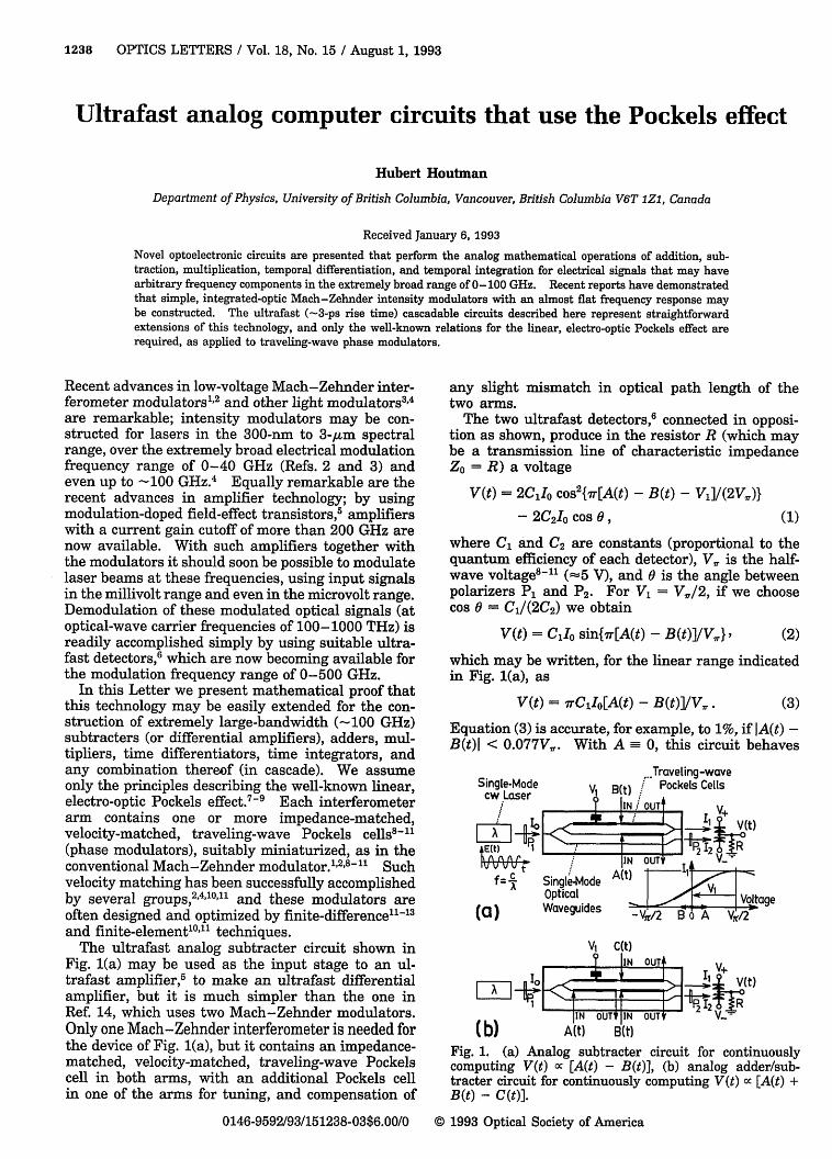
The ultrafast analog subtracter circuit shown inFig. 1(a) may be used as the input stage to an ul-trafast amplifier,5 to make an ultrafast differentialamplifier, but it is much simpler than the one inRef. 14, which uses two Mach-Zehnder modulators.Only one Mach-Zehnder interferometer is needed forthe device of Fig. 1(a), but it contains an impedance-matched, velocity-matched, traveling-wave Pockelscell in both arms, with an additional Pockels cellin one of the arms for tuning, and compensation of
any slight mismatch in optical path length of thetwo arms.
The two ultrafast detectors,6 connected in opposi-tion as shown, produce in the resistor R (which maybe a transmission line of characteristic impedanceZO = R) a voltage
V(t) = 2CIo cos2{ir[A(t) - B(t) - Vl]/(2V,)l- 2C2I0 cos a, (1)
where C1 and C2 are constants (proportional to thequantum efficiency of each detector), V1, is the half-wave voltage8-"1 (-5 V), and 0 is the angle betweenpolarizers P1 and P2. For V, = V./2, if we choosecos 0 = C1 /(2C2 ) we obtain
V(t) = C,1o sin{Tr[A(t) - B(t)]/V1. }' (2)
which may be written, for the linear range indicatedin Fig. 1(a), as
V(t) = rCjIo[A(t) - B(t)]/V,.. (3)
Equation (3) is accurate, for example, to 1%, if IA(t) -B(t)I < 0.077V',. With A 0, this circuit behaves
SgMTraveling-waveSingle-Mode V 1 B(t) Pockels Cells
cw raser IIN OUT
LL X IF*He0 Vlt)NOU
f = SingleMode A(t)I OpticalIi Waveguides Voltage,.
'-I
(b)
V1 C(t)? IN OUT*
1, 11 I Yj(t)
-+P- 1 -OT IN OUT _R
. . ~~IIN OUTV IN OUT* \/--
AIt) B(t)
Fig. 1. (a) Analog subtracter circuit for continuouslycomputing V(t) cc [A(t) - B(t)], (b) analog adder/sub-tracter circuit for continuously computing V(t) cc [A(t) +B (t) - C (t)].
as an inverter, to give -B(t). The dynamic rangewill depend on the laser linewidth and other experi-mental details, but it may be improved with variouslinearization techniques.'5
If both traveling-wave Pockels cells were placed inthe same arm, we could construct an ultrafast analogadder circuit in a similar fashion, which would havean output voltage
V(t) = g-C1Io[A(t) + B(t)]/V1. . (4)
This concept may be extended further by introducingadditional Pockels cells into either arm as needed,and an example is shown in Fig. 1(b). With the sameargument as above, for input voltages A(t), B(t), andC(t), the output voltage for Fig. 1(b) is
V(t) = v-C1Io[A(t) + B(t) - C(t)]/V 1. , (5)
for signals that satisfy IA(t) + B(t) - C(t)l < 0.077V1.,for a 1% accuracy. If the A(t) output is connectedto the C(t) input, through a short transmission lineof delay At, this circuit will function as a time-differentiator circuit, with an output
for frequencies below approximately (10At)1. Sim-ilarly, other finite-difference formulas, for d2A/dt2 ,etc., may be implemented as well.
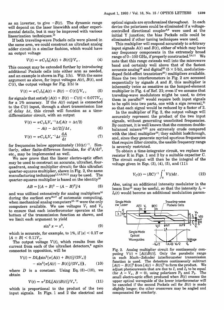
We now prove that the linear electro-optic effectmay be used to construct an accurate, ultrafast, four-quadrant, analog multiplier circuit; for this ultrafastquarter-squares multiplier, shown in Fig. 2, the samemanufacturing techniques124'8"10"' may be used. Thequarter-squares multiplier is based on the identity16
AB = [(A + B)2 - (A - B)2 ]/4 (8)
and was utilized extensively for analog multipliers16during the earliest era'167 of automatic computing,when mechanical analog computers16-' 8 were the onlycomputers available. We use voltages VI and V2to ensure that each interferometer operates at thebottom of the transmission function as shown, andwe limit each argument to yield
sin2 X = X2, (9)
which is accurate, for example, to 1%, if Ixi < 0.17 orIA ± BI < 0.11V1 .
The output voltage V(t), which results from thecurrent from each of the ultrafast detectors,6 againconnected in opposition, will be
V(t) = DIO(sin2{7i-[A(t) + B(t)]/(2V1.)}
- sin2{-7r[A(t) - B(t)]/(2V1.)}), (10)
where D is a constant. Using Eq. (8)-(10), weobtain
V(t) = Ir2DIo[A(t)B(t)]/V1'2, (11)
which is proportional to the product of the twoinput signals. In Figs. 1 and 2 the electrical and
optical signals are synchronized throughout. In eachdevice the polarizers could be eliminated if a voltage-controlled directional coupler8'9 were used at theinitial Y junction; the bias Pockels cells could beeliminated if other tuning techniques were used.
This multiplier will respond accurately to arbitraryinput signals A(t) and B(t), either of which may haveany frequency components in the extremely broadrange of 0-100 GHz, if properly constructed.2 4 "' Wenote that this range extends well into the microwaveband and certainly well above that of the fastestaccurate analog19 and digital20 (5 x 5 bit, modulation-doped field-effect transistors2 0) multipliers available.Since the two interferometers in Fig. 2 are accessedsequentially by signals A and B, this multiplier isinherently twice as sensitive as the lumped-elementmultiplier in Fig. 4 of Ref. 21; even if we assume thattraveling-wave modulators might be used, to drivethem in parallel2 ' would require both input signalsto be split into two parts, one with a sign reversal,21so that each signal would be reduced by a factor of 2.
In the multiplier of Fig. 2, the output voltage willaccurately represent the product of the two inputsignals, without generating unsolicited frequencies.By contrast, it is well known that the common double-balanced mixers1922 are extremely crude comparedwith the ideal multiplier'9 ; they exhibit leakthrough,and, since they generate myriad spurious frequenciesthat require filter circuits, the usable frequency rangeis severely restricted.
To obtain a time-integrator circuit, we replace theresistor R in Figs. 1 and 2 by a suitable capacitor C.The circuit output will then be the integral of thevoltage given in Eqs. (3), (4), (5), and (11):
tVc(t) = (RC)-i V(t)dt. (12)
Also, using an additional intensity modulator in thebeam line'5 may be useful, so that the intensity Io =10(t) would become an additional modulation param-
Fig. 2. Analog multiplier circuit for continuously com-puting V(t) a [A(t)B(t)]. Only the parabolic rangein each Mach-Zehnder interferometer transmissionfunction is used. The detectors continuously subtract[A(t) - B(t)]2 from [A(t) + B(t)]2 to form the product. Weadjust photocurrents that are due to I, and 12 to be equal(for A = V1., B = 0), using polarizers P2 and P3 . Thesmall electro-optic effect produced when B(t) crosses theupper optical waveguide of the lower interferometer willbe canceled if the second Pockels cell for B(t) is madeslightly longer; the other crossovers may be angled andcompensated for similarly.
eter in Eqs. (3)-(5), (7), (11), and (12); these circuitsmay also be switched on and off (for gates in ultra-fast analog computers) and/or modulated2 3 by logiccircuits8'9'21 by using such methods. A divider circuitto compute [A(t)/B(t)] may also be constructed, witha subtracter circuit as in Fig. 1(a), an amplifier,5and a multiplier as in Fig. 2, connected in the usualservo-loop configuration,'6"7 but -the bandwidth willdepend on the loop delay. One of the interferometersin Fig. 2 would function as a'squarer, to compute[A(t)]2, for frequency doubler, tripler, and quadruplerapplications, etc. "
Any of these devices may also be constructedwith macroscopic traveling-wave Pockels cells9'23
and would result in reduced (but still respectable)frequency ranges near 0-5 GHz. It would then benecessary to use the crossed-polarizer configura-tion,7- 923 since with a macroscopic Mach-Zehnderconfiguration24 phase drift (which results from vi-bration and temperature variations) would precludesatisfactory operation.
The devices of Figs. 1 and 2 may be connected incascade, or in loops, for more-complicated operationssuch as [A2BC - B3 - A(dC/dt) + BC fABdt]; sincethe detector output will typically be much less than 1V, laser and/or electrical amplifiers5 will be requiredbetween stages. Electrical inputs and outputs, in-cluding their ground conductors (not shown), may beisolated, so cross-talk and cross-coupling effects maybe completely eliminated. The detectors may be atremote locations for ultrawideband, wireless signaltransport, data links, and delay lines. To test thesecircuits in the time domain would require an ultrafastreal-time oscilloscope13 or sampling techniques 2 5 ; thecircuits could also be used as the input stage in thesedevices.' 3 ,25
These general-purpose mathematical circuits willbe useful for ultrafast proportional-integral-derivative control systems, telecommunications,radar, signal processing, analog computers, andsignal-generation systems. The computation ratewould be near 4 X 101" operations per second, or-0.4 teraflop (the Nyquist rate for an -200-GHzoutput), which is approximately 200 times fasterthan with typical analog'9 or digital20 circuits. Thesecircuits will be useful as an analog front end, pro-viding preview computations in analog/digital hybridcomputers,26 control systems, and feedback loops,while one waits for the digital circuit (connectedin parallel) to update the same computations withincreased accuracy. Other uses include digital (shiftkey, etc.) modulation, analog modulation, demodula-tion, frequency conversion, mixing, signal transportand delay, rf switching, and microwave switchingof high-frequency electrical signals, with arbitraryspectra in the range of 0-100 GHz; the frequencyrange will increase with further advances in in-tensity modulator,2 4 10'1 ' detector, 6 and amplifier 5
technology.
References
1. W. E. Martin, Appl. Phys. Lett. 26, 562 (1975).
2. C. C. Teng, Appl. Phys. Lett. 60, 1538 (1992); K.Noguchi, 0. Mitomi, K. Kawano, and M. Yanagibashi,IEEE Photon. Technol. Lett. 5, 52 (1993).
3. 0. Mitomi, I. Kotaka, K. Wakita, S. Nojima, K.Kawano, Y. Kawamura, and H. Asai, Appl. Opt. 31,2030 (1992).
4. J. Nees, S. Williamson, and G. Mourou, Appl. Phys.Lett. 54, 1962 (1989).
5. L. D. Nguyen, L. E. Larson, and U. K. Mishra, Proc.IEEE 80, 494 (1992).
6. S. Gupta, S. L. Williamson, J. F. Whitaker, Y. Chen,and F. W. Smith, Laser Focus World 28(6), 97 (1992);S. Y. Chou and M. Y. Liu, IEEE J. Quantum Electron.28, 2358 (1992); K. S. Giboney, M. J. W. Rodwell, andJ. E. Bowers, IEEE Photon. Technol. Lett. 4, 1363(1992).
7. F. Pockels, Lehrbuch der Kristalloptik (Teubner,Leipzig, Germany, 1906), pp. 492-510.
8. R. G. Hunsperger, Integrated Optics: Theory andTechnology, 3rd ed. (Springer-Verlag, Berlin, 1991),pp. 1-347; M. Iizuka, Engineering Optics, 2nd ed.(Springer-Verlag, Berlin, 1987), pp. 341-479.
9. B. E. A. Saleh and M. C. Teich, Fundamentals ofPhotonics (Wiley, New York, 1991), pp. 238-309,460-917; H. A. Haus, Waves and Fields in Op-toelectronics (Prentice-Hall, Englewood Cliffs, N.J.,1984), pp. 158-338; I. P. Kaminow, An Introductionto Electrooptic Devices (Academic, New York, 1974),pp. 1-409.
10. H. Miyamoto, H. Ohta, K. Tabuse, and Y. Miyagawa,Jpn. J. Appl. Phys. (Pt. 1) 31, 2116 (1992).
11. N. A. F. Jaeger and Z. K. F. Lee, IEEE J. QuantumElectron. 28, 1778 (1992).
12. H. Houtman, F. W. Jones, and C. J. Kost, in XIII Inter-national Conference on Cyclotrons and Their Applica-tions (World Scientific, Singapore, 1993), pp. 411-414.
13. H. Houtman, "Laser oscilloscope," Plasma Physics Lab.Rep. 144 (University of British Columbia, Vancouver,Canada, 1992).
14. M. H. Berry and D. M. Gookin, IEEE Photon. Technol.Lett. 3, 276 (1991).
15. C. H. Chao, P. Y. Chien, L. W. Chang, F. Y. Juang,C. H. Hsia, and C. C. Chang, Opt. Lett. 18, 131 (1993).
17. W. J. Karplus and W. W. Soroka, Analog Methods/Computation and Simulation, 2nd ed. (McGraw-Hill,New York, 1959), pp. 102-200.
18. H. Houtman, Rev. Sci. Instrum. 58, 1507 (1987); 61,1151 (1990); Am. J. Phys. 52, 468 (1984).
19. P. Cofrancesco, P. Mustarelli, and U. Ruffina, Mi-crowave J. 34(12), 58 (1991); B. Gilbert, IEEE J.Solid State Circuits SC-3, 365 (1968); Special LinearReference Manual (Analog Devices, Norwood, Mass.,1992), pp. 2-67-2-74.
20. D. K. Arch, B. K. Betz, P. J. Vold, J. K. Abrokwah,and N. C. Cirillo, IEEE Electron Device Lett. EDL-7,700 (1986).
21. H. F. Taylor, Proc. IEEE 75, 1524 (1987).22. W. Fraser, Telecommunications (Macdonald, London,
1957), pp. 397-467.23. H. Houtman and J. Meyer, Opt. Lett. 12, 87 (1987); J.
Appl. Phys. 61, 843 (1987).24. H. Houtman, L. E. Legault, and J. Meyer, Appl. Opt.
26, 1106 (1987).25. M. Y. Frankel, J. F. Whitaker, and G. A. Mourou,
IEEE J. Quantum Electron. 28,2313 (1992); U. D. Keiland D. R. Dykaar, Appl. Phys. Lett. 61, 1504 (1992).
26. G. A. Bekey and W. J. Karplus, Hybrid Computation(Wiley, New York, 1968), pp. 1-464.
![[Razavi] Design of Analog Cmos Integrated Circuits](https://static.documents.pub/doc/80x56/563dbb66550346aa9aacd910/razavi-design-of-analog-cmos-integrated-circuits.jpg)


