Ultrahigh Speed Photography of Picosecond Light Pulses and Echoes M. A. Duguay and A. T. Mattick Three new results have been obtained with a recently developed camera of 10-psec framing time: (1) The effect of the finite speed of light in photographing relativistic objects is experimentally demonstrated, by photographing a dumbbell-like entity formed by two packets of light. In contrast to material objects, which, theory predicts, should appear rotated, the light dumbbell appears sheared. (2) Photographs of the mode-locked Nd: glass laser radiation show numerous subsidiary pulses accompanying the main ultrashort pulses in the train. The latter have durations ranging from 7 psec to 15 psec. (3) The tech- nique of gated picture ranging, previously used with nanosecond pulses, is extended to the picosecond range where a resolution of 1 cm is demonstrated. Some potentially useful applications are proposed. Introduction Work in ultrahigh speed photography' has been carried out so far with the help of cameras capable of nanosecond and subnanosecond2 framing times. These cameras have proved very useful, in particular in the study of rapidly expanding plasmas produced by lasers. 3 The recent development of a new Kerr-type shutter, 4 capable of picosecond framing times, has opened new possibilities. One is the direct photo- graphing of light pulses in flight through a scattering medium. 2 ' 6 This appears to be a convenient technique for displaying and measuring ultrashort light pulses. 6 In this paper we describe three new applications of the ultrafast camera. First, we show how light packets appear deformed under ultrahigh speed photography. It has long been predicted that relativistic material objects will appear rotated when stop-motion photographed. 8 By con- trast, we show that light packets in general appear sheared along the direction of travel. This shear effect is illustrated by ultrahigh speed pictures of a dumbell-like packet of light. Secondly, taking advantage of the ultrafast camera's high contrast, we study the intensity time profile of our mode-locked Nd: glass laser beam in the vicinity of the main ultrashort pulses. The latter are found to be persistently accompanied by numerous subsidiary Both authors were with Bell Telephone Laboratories, Inc., Murray Hill, New Jersey 07974 when this work was done; A. T. Mattick is now with the Massachusetts Institute of Technology. Received 23 April 1971. pulses in agreement with previous work. 9 Some of these occur at a fixed spacing from the main ultrashort pulse and carry a power density comparable to that of the main ultrashort pulse. Other subsidiary pulses are -25 times weaker than the main ultrashort pulse and appear randomly from shot to shot. The pulse dura- tions vary from 7 psec to 15 psec. Thirdly, we present results of gated picture ranging obtained with the ultrafast camera. This work ex- tends to the Picosecond Domain, a technique previously employed to "see through" fog, whereby one sends out a nanosecond illuminating pulse and selectively records the echo image sent back by the target by gating on (for a few nanoseconds) an image converter tube at the expected echo arrival time.' 0 With the 10-psec pulses available from the Nd:glass laser we have resolved echo images from objects 1 cm apart and "seen through" thin tissue. An incentive for pursuing this work may arise in the near future if subpicosecond pulses become readily available. These would permit picture ranging with submillimeter resolution and this might lead to interesting medical applications, such as seeing through the human skin. Experimental: The Ultrafast Camera The experimental setup used to photograph pico- second light pulse in flight is shown in Fig. 1, and a typical result is shown in Fig. 2. A mode-locked Nd: glass laser' of optical length L generates a train of ultrashort pulses which has a periodicity 2L/c equal to 5 nsec. Our ultrashort pulses (at a wavelength X = 1.06 ) have a duration of the order of 10 psec' 2 and green pulses derived from they by second harmonic generation are expected to be approximately a factor of \2 shorter (neglecting the pulse-broadening effects 2162 APPLIED OPTICS / Vol. 10, No. 9 / September 1971
Transcript
Ultrahigh Speed Photography of PicosecondLight Pulses and Echoes
M. A. Duguay and A. T. Mattick
Three new results have been obtained with a recently developed camera of 10-psec framing time: (1)The effect of the finite speed of light in photographing relativistic objects is experimentally demonstrated,by photographing a dumbbell-like entity formed by two packets of light. In contrast to material objects,which, theory predicts, should appear rotated, the light dumbbell appears sheared. (2) Photographs ofthe mode-locked Nd: glass laser radiation show numerous subsidiary pulses accompanying the mainultrashort pulses in the train. The latter have durations ranging from 7 psec to 15 psec. (3) The tech-nique of gated picture ranging, previously used with nanosecond pulses, is extended to the picosecondrange where a resolution of 1 cm is demonstrated. Some potentially useful applications are proposed.
Introduction
Work in ultrahigh speed photography' has beencarried out so far with the help of cameras capable ofnanosecond and subnanosecond2 framing times. Thesecameras have proved very useful, in particular in thestudy of rapidly expanding plasmas produced bylasers.3 The recent development of a new Kerr-typeshutter, 4 capable of picosecond framing times, hasopened new possibilities. One is the direct photo-graphing of light pulses in flight through a scatteringmedium.2' 6 This appears to be a convenient techniquefor displaying and measuring ultrashort light pulses.6
In this paper we describe three new applications of theultrafast camera.
First, we show how light packets appear deformedunder ultrahigh speed photography. It has long beenpredicted that relativistic material objects will appearrotated when stop-motion photographed. 8 By con-trast, we show that light packets in general appearsheared along the direction of travel. This sheareffect is illustrated by ultrahigh speed pictures of adumbell-like packet of light.
Secondly, taking advantage of the ultrafast camera'shigh contrast, we study the intensity time profile of ourmode-locked Nd: glass laser beam in the vicinity ofthe main ultrashort pulses. The latter are found to bepersistently accompanied by numerous subsidiary
Both authors were with Bell Telephone Laboratories, Inc.,Murray Hill, New Jersey 07974 when this work was done; A. T.Mattick is now with the Massachusetts Institute of Technology.
Received 23 April 1971.
pulses in agreement with previous work.9 Some ofthese occur at a fixed spacing from the main ultrashortpulse and carry a power density comparable to that ofthe main ultrashort pulse. Other subsidiary pulses are-25 times weaker than the main ultrashort pulse andappear randomly from shot to shot. The pulse dura-tions vary from 7 psec to 15 psec.
Thirdly, we present results of gated picture rangingobtained with the ultrafast camera. This work ex-tends to the Picosecond Domain, a technique previouslyemployed to "see through" fog, whereby one sends out ananosecond illuminating pulse and selectively recordsthe echo image sent back by the target by gating on(for a few nanoseconds) an image converter tube at theexpected echo arrival time.' 0 With the 10-psec pulsesavailable from the Nd:glass laser we have resolvedecho images from objects 1 cm apart and "seen through"thin tissue. An incentive for pursuing this work mayarise in the near future if subpicosecond pulses becomereadily available. These would permit picture rangingwith submillimeter resolution and this might lead tointeresting medical applications, such as seeing throughthe human skin.
Experimental: The Ultrafast Camera
The experimental setup used to photograph pico-second light pulse in flight is shown in Fig. 1, and atypical result is shown in Fig. 2. A mode-lockedNd: glass laser' of optical length L generates a train ofultrashort pulses which has a periodicity 2L/c equalto 5 nsec. Our ultrashort pulses (at a wavelengthX = 1.06 ) have a duration of the order of 10 psec'2
and green pulses derived from they by second harmonicgeneration are expected to be approximately a factor of\2 shorter (neglecting the pulse-broadening effects
discussed in Ref. 13). The green pulses are sent via avariable optical delay line into a rectangular cell con-taining a colloidal suspension of milk particles' 4 in a20: 1 water-alcohol mixture. The suspension con-centration is normally adjusted to scatter -4% of thelight per centimeter. It is important that the greenpulses be vertically polarized so that much of the lightis scattered toward the camera. The green pulses thusbecome brightly visible and are photographed from theside by the shutter and camera arrangement shown inFig. 1.
The ultrafast shutter is a new type of Kerr cell wherebirefringence is induced directly by the ultrashortinfrared pulses.4 The shutter consists of an ordinary(electrodeless) cell containing CS2 placed between twocrossed polarizers Pi and P2 of type HN22 (Polaroid).The cell has a thickness = 1 cm and is held gently toavoid strain birefringence. The infrared pulses are
V BREWSTERsA• ANGLE PLATES
DYE CELL
AR t d
| KDP
X k= 0.53
10 psec \ 4.--7 P-_ XI BEAM SPLITTER I
X=1.06/L I I
Il MILKY WATER
-E~ IGREEN
I- I I,-+_coo"I
tXCS~~~C2 X-J75
P2 X FILTER MOVABLEPRISM
IRIS
Fig. 1. Experimental setup for photographing light pulses inflight. Movable prism provides for an adjustable delay line.Laser produces a train of ultrashort pulses nominally 5 nsecapart. Delay line is adjusted so that as the nth green pulse inthe train traverses the water cell the shutter is being opened bythe (n + 1)th infrared pulse. Pulses are represented by theirapproximate envelopes. Their inner structure remains unknown.Filter F absorbs the infrared pulses but transmits well in the
visible.
Fig. 2. Photograph of ultrashort green pulse in flight (fromright to left) through the milky water. Scale is in millimeters inwater. Shutter opening time was 10 psec. Photograph wasoriginally recorded on a high speed Ektachrome color slide in onelaser shot. This black and white reproduction is somewhat over-exposed to satisfy publication requirements. On a properlyexposed photograph the length of the spot is approximately equalto the length of the infrared pulses which drive the shutter andalso give rise to the green pulses. The round spot to the left ofthe water cell was produced by the infrared pulses entering thecamera head-on and being residually transmitted by filter F
shown in Fig. 1.
plane-polarized in the plane of Fig. 1 and have anestimated power density of -100 MW/cm 2 at the CS2cell. There they induce a time-dependent birefringence(3n an) given by:"
at
w ne -an = 2B E'(t') exp[(t' - t)/r ]dt', (1)T -
where E2(t') is the squared optical field averaged overone optical period, t and t' are time variables, r is therelaxation time of the Kerr effect in the medium usedfor the shutter (r < 2 psec for CS2), and n2B is the non-linear Kerr index" (2.2 X 10⁻²⁰ m2/V2 = 2 X 10-esu for CS2). Our pulses being 7 psec in width, weneglect the 2-psec time convolution and use the approxi-mation
An- n = n2BE'(t). (2)
When the pulse reaches its peak power density of 100MW/cm 2 (E = 19.4 X 10' V/m), the induced birefrin-gence reaches 0.84 X 10-' for a brief moment.
Two other time-smearing factors tend to lengthenthe shutter response time. One is a 2-psec groupvelocity differential delay between the green andinfrared in the 1-cm CS2 cell.7 The other is a 1.8-psecdifference in shutter turn-on time experienced byscattered green light spread out over the 4-mm iris dueto the finite angle (a = 8) between the infrared andthe green light at the CS2 cell. The effects of the CS2
lifetime and these two time factors combine approxi-mately quadratically (square root of the sum of thesquares) with the duration of the infrared pulse. Ifthe infrared pulse were a function, the shutter openingtime would be 3 psec. Since our pulses are >7 psecin duration, the error on the shutter response time in-curred by neglecting these factors will be <1 psec, andwe shall do so in the following.
In Fig. 1, polarizer PI is at 450 to the vertical. Theshutter transmission T for that component of scatteredgreen light polarized along PI is given in the case ofideal nonabsorbing polarizers by4
,7
T = sin'(r en2BE2/X) = 0.23, (3)
where we have used the numerical values quoted so far(X = 0.53,g). Thus, at the relatively low power densi-ties involved here, the shutter transmission T isapproximately (in the sense sinx 2 x2) proportional toE4(t), i.e., to the squared infrared intensity 1 2(t):
T(t) E4(t) 12(t) for E < 20 X 10' V/rn. (4)
The shutter framing time [full width at half-height ofT(t) ] is thus approximately equal to the duration of thesquared infrared pulse. For a typical 10-psec infraredpulse, this means a shutter time of 7 psec. Since thepulses fluctuate over the range 7-15 psec, we shall oftenuse the figure 10 psec as the nominal shutter time inthis paper.
The peak shutter transmission observed in practiceis less than the 23% estimated in Eq. (3). Photo-graphic measurements indicate that it fluctuates from1% to 2%, depending on the laser shot. This is dueto absorption in the polarizers and in the infraredfilter, imperfect collinearity between the gating infraredbeam and the gated green light, and the fact that thescattered green light is predominantly verticallypolarized, so that only 50% of it is parallel to Pi andcan be gated through.4 3 At times, we would amplifythe 1.06-u pulses in a laser amplifier of gain 4. Thegate transmission would then be observed to range from5% to 10%, depending on the laser shot. The diameterof the iris in Fig. 1 was adjusted to be 4 mm so that thecamera only looked through the birefringence window.With the iris in place the effective camera aperturewasf/25.
The iris plays an important role in reducing theamount of light recorded by the film when the gate isoff. In the absence of the gating infrared pulses, theKerr cell transmission is about 0.005%, most of thisbeing due to residual birefringence in the infraredfilter. As a result, the on-off ratio of the gate variesfrom 200 to 400, giving rise to very high contrastpictures of the ultrashort pulse.'7 In the absence of theiris, the on-off ratio becomes much worse because thefull aperture of the lens is exposed to light leakingthrough the crossed polarizers when the gate is off, sothat the f/number for this unwanted light is f/4,thereby reducing the on-off ratio by a factor of (25/4)2 = 39; in this case the spot in Fig. 2 appears to beriding on a faint background track.
1. Shearing of Light Dumbbell
Relativistic material objects have not yet beenstop-motion photographed in the lab, but it has beenpredicted that when they are photographed, they willappear rotated, not simply Lorentz-contracted.'Lorentz contraction does take place, but its action com-bines with the wave propagation effect to make ma-terial objects appear purely rotated. 8 (This is underthe assumption that objects subtend a small solid angleat the camera and that the depth of focus encompassesthe whole object, a condition also met in our experi-ment.)
A pulse of laser light (or light packet) is an entitywith a given distribution at a given time, and we cantherefore speak about its three-dimensional shape.For low diffraction laser beams, this shape remainssubstantially the same as the pulse propagates for ashort distance in a transparent medium. Since thepulse moves at a relativistic speed, it is relevant to askwhether it too will appear simply rotated. The answeris that the light packet will in general appear shearedalong the direction of motion when viewed at 900 to thebeam. This shear effect can be understood as arisingfrom a wave propagation effect without recourse to thetheory of special relativity; it does not contradictTerrell's theory, because the latter strictly deals withmaterial objects.
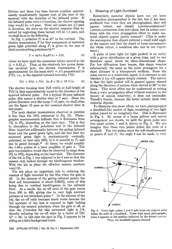
To illustrate this shear effect, we have photographeda dumbbell-like packet of light consisting of two lightpulses joined by an imaginary line. This is illustratedin Fig. 3. By means of a beam splitter and mirrorarrangement not shown, we split the green pulse intotwo equal pulses, 1 and 2, shown in Fig. 3. We canimagine that these two pulses define the ends of adumbell. The two pulses enter the cell simultaneouslyat points R and P; the angle 0 can be made to vary
WATER CELL
DUMBBELL _ _
Fig. 3. Green light pulses 1 and 2 split from one original pulsedefine the ends of a dumbbell. Under high speed photography,pulse 2 appears at the position indicated by the dotted contour.
Fig. 4. Four ultrahigh speed photographs of a dumbbell-shapedlight packet illustrating the shear effect. (a) Dumbbell is andappears vertical. (b)-(d) Upper part of dumbbell is rotatedaway from the camera, which the reader can imagine to be in hishands. A nonrelativistic material dumbbell would appear in(d) with its two ends superimposed. Instead, the light dumbbell
appears sheared in the direction of propagation.
from 0 to 900 by rotating our mirror arrangement.When the dumbbell is vertical ( = 900 in Fig. 3), theresulting picture [Fig. 4(a) ] shows the dumbbell in itsactual position. Figure 4(b) through (d) shows howthe picture changes as we gradually rotate the dumbbellaway from the vertical until it lies in the horizontalplane; pulse 2 now appears to be falling behind pulse 1although the two did enter the cell simultaneously.The reason for this is that pulse 2 is being photographedat a time advanced by T' = s/v0 relative to the time atwhich pulse 1 is photographed, where s is the x-abscissadifference between the pulses and v is the groupvelocity of light in the medium. When the shutteropens briefly at the right time t to photograph pulse 1at the position it occupies in Fig. 3, no scattered lightfrom pulse 2 traverses the shutter because of the addi-tional delay T' that light from pulse 2 suffers on itsway to the camera. However, light scattered frompulse 2 at the earlier time t -T' now arrives at just theright time to cross the shutter. As shown by thedotted contour in Fig. 3, pulse 2 should appear dis-placed to the right by s cm. In Fig. 4(d) pulse 2 indeedappears 1 cm to the right of pulse 1, i.e., in the positionit occupied 45 psec earlier.
When photographing an arbitrarily shaped lightpacket, we can imagine the object as consisting of anumber of thin slices cut perpendicularly to the cameraaxis x. Although all the thin slices are photographedfaithfully, they appear on the film gradually displacedto the right in proportion to their distance from thecamera. Consequently, the light packet appearssheared in the direction of travel. Mathematically,this shear can be seen in the expression for the im-age recorded on film by an infinitely fast camera:'
B(y', z', ) = f u(xy,z - vt - D - x)dx. Here,B is the optical density recorded on the film character-ized by axis OY' and OZ' parallel to OY and OZ inFig. 3, u is the energy density in the light packet,locally averaged over a few cubic wavelengths, t is thetime at which the shutter opens, v is the group velocityof light in the scattering medium, and D is the opticaldistance from the shutter to point 0 in Fig. 3.
The shear effect arises from the integral over thedepth x. It introduces a time-smearing factor .xequal to Ax/v,, where Ax is the depth of the light packet.When we photograph light pulses to study their timeprofile, it is therefore desirable to reduce the beam sizein the x direction to a minimum. In our experimentalsetup an inverted telescope, not shown in Fig. 1,collimated the green beam to a 1-mm diameter. Theshear effect therefore increased the apparent pulselength by about 1 mm. This factor was taken intoaccount in the detailed analysis of the spot shapepresented in Ref. 7.
To conclude this section, it is interesting to compareour experiment with Terrell's gedanken experimentsinvolving the photography of relativistic materialobjects. Terrell finds that relativistic objects wouldappear simply rotated regardless of the relative posi-tions and velocities of observer and object.8 Thisapparent rotation can be thought of as arising from twoeffects: (1) the object is Lorentz-contracted along itsdirection of motion, say OZ as in Fig. 3, and (2) theshear effect described above takes place as a result ofthe finite speed of propagation of light. Thus amatchstick, parallel to and moving along OZ in Fig. 3at 86.6% of the speed of light, would be contracted bya factor of 2, and as it passed directly in front of thethe camera, its back end face would show up on thephotograph for reasons analogous to those expoundedin connection ith Figs. 3 and 4. As a result thematchstick would appear rotated 600 away from OZtowards OX. In the present experiment, on the other-hand, the laser is stationary and the emitted pulse isnot Lorentz-contracted so that only an apparent sheartakes place.
A case where Terrell's and our descriptions almostcoincide is that of infinitesimally thin coin-shapedmaterial or light entities moving head-face-first alongthe Z axis. In this case both an ultrarelativistic coin(v/c > 0.99) and a light coin appear with their backfacing the camera as if they had been rotated by 90 ornearly 900 (slower coins appear rotated by a lesserangle). The changed appearance of these coins can beinterpreted by the observer as the result of a shear or arotation. In reality the coins have, of course, beenneither sheared nor rotated.
We have treated our laser pulses as of given shapeand not Lorentz-contracted from something else. Aswas pointed out to us,4 5 even light pulses can be subjectto Lorentz contraction. To a 250-MeV electronmoving towards our 10-psec pulses at 99.9998% of thespeed of light, the pulses appear up-shifted into thex-ray range by the doppler shift factor 2(1 - v2 /c2) -
equal to 1000. Since the number of optical cycles is
conserved, our pulses would appear contracted to10 fsec to an observer riding along with the electron.4 'The electromagnetic energy reflected by the electrontowards the laser appears in the lab as a y-ray pulse4
again further contracted by nearly the doppler shiftfactor to 10 asec.47 The role of Lorentz contraction inthe photography of such y-ray pulses would thereforebe quite dramatic. In our experiment, however,Lorentz contraction played no role because the laserwas stationary with respect to the camera.
2. Structure of the Nd :Glass Laser Pulse Train
The time structure of the Nd:glass laser output hasbeen studied extensively in the last few years," " 2 '8mainly by the method of two-photon fluorescence 9
and with the help of ultrafast streak cameras.9' 20This work has established that the dye mode-lockedNd: glass laser generates pulses 5-20 psec"I in duration,spaced, in principle, by the cavity round-trip time2L/c (5 nsec in our laser), where L is the optical lengthof the resonator. In practice, more than one ultra-short pulse per cavity round-trip time has been ob-served,9 especially in lasers such as ours, where themode-locking dye cell is spaced by some distance dfrom one of the laser mirrors. The presence of addi-tional or satellite pulses, spaced 2d/c from the mainpulse, is a common occurrence in such lasers.9 Evenin lasers with dye cells in contact with one of the lasermirrors, 2 ' additional smaller pulses arise.22 Auston,23
using a new pulse-measuring technique of very highsensitivity, has shown recently that the time-averagedbackground between the main ultrashort pulses has avalue of _10-4 relative to the main pulse peak powerin a laser considered well mode-locked by a contacteddye cell.
The ultrafast camera setup of Fig. 1 is wvell suited tolook at subsidiary pulses because of the high contrastratio available (up to 2000). We have used it to studythe satellites at 2d/c from the main pulse and othersubsidiary pulses as a function of various laser param-eters. Before examining these results, however, it iswell to analyze briefly the nature of these measure-ments.
(a) Correlation. Function G4(r)
If in the setup of Fig. 1 a single infrared ultrashortpulse, of known shape, were used to open the shutter,the analysis of the results would be relatively simple;one would be dealing with a single photograph of thegreen light beam or of whatever else one was photo-graphing. Some linear motion blurring would alwaystake place because of the finite shutter framing time(during our nominal 10-psec framing time the greenpulses move 2.2 mm in water). Sometimes suchblurring can be successfully corrected for in conven-tional photography. 2 4
In the present case, however, the infrared ultrashortpulses have a complex shape, including a subpico-second substructure, that has not yet been determined.' 2
In addition, there is a number (call it N) of ultrashort
pulses in each cavity round-trip time interval (2L/c =5 nsec). The shutter, therefore, opens N times duringeach 2L/c interval and the green light beam is photo-graphed N times. This multiple exposure is undesir-able because the green beam moves forward with eachexposure, and this prevents one from reconstructingthe precise shape of the green beam.48 This number ofexposures N is again multiplied by the number of2L/c intervals in the Q-switched train (10-20). Sincethe beam structure more or less repeats itself every2L/c nsec, this leads to a repeated exposure of the samepattern and is not as serious a drawback as the afore-mentioned multiple exposure.
Mathematically, what is being measured is a fourth-order correlation function G(4) (T). Both the shuttertransmission T(t) and the harmonically generated greenlight are proportional to the squared infrared intensity12 (t). For a green beam of negligible thickness alongthe camera axis OX (see Fig. 3), the recorded lightdensity F(z) integrated over x and y is
that is,
(5)F(z) f12(t)I2(t + zv, + b)dt,F(z) G4(r),
where T = z/v, is the time equivalent of distance inwater and b is a constant. When the green beam hasa finite thickness As along the X axis, a local z-averagingtakes place inside Eq. (4) over an interval Az = As (seeRef. 7). This effect amounted to only As = 1 mm inour experiment and we can neglect it.
The quantity measured here is therefore a correlationfunction of the same class as those measured in variousnonlinear optic experiments, for example, in two-photon fluorescence. Although one cannot unambigu-ously reconstruct the original intensity profile 1(t) froma measurement of GW4) (T) (see Ref. 25), one can estimatethe widths of the pulses involved, their number, andrelative sizes and spacings. If we assume, for sim-plicity, that the infrared pulses are roughly gaussian-shaped,3 7 then it follows from Eq. (6) that F(z) is alsogaussian-shaped with the same width parameter asI(t). The spot length in Fig. 2 and others is thereforeapproximately equal to the width of the infrared pulsesproduced by the laser. However, since in this paperthe pulses were deliberately overexposed to satisfypublication requirements, the spot length gives thewidth of the infrared pulse at -10% of maximumheight rather than at half-height. A photodensi-tometer tracing of one properly exposed photographis shown by the solid line in Fig. 5(a). The widthat half-height is 3.9 mm (air equivalent, 2.9 mm inwater) or 13 psec. This implies that the averagewidth of the infrared pulses was -12 psec in this case,making a small allowance for the time factors alludedto above.
One of these time factors, the Kerr effect relaxationtime, is very dramatically exhibited by the dottedcurve in Fig. 5(a), representing a case where nitro-benzene was poured into the shutter. The relaxationtime of nitrobenzene being 32 psec,4 Eq. (1) must beapplied in this case, and the data can be used to measure
Fig. 6. Three pictures were taken at different delays to show themain pulse and the satellites at 2d/c = 12 cm on either side.Satellites are due to the spacing d between the mode-looking dyecell and one laser mirror and could not be eliminated by changingvarious laser parameters. Scale is in equivalent centimeters of
air.
"MAIN" PULSE
LASER
0 I I I I X
42 38 30 26Z(cm)
18 14 10
Fig. 5. (a) Solid curve is a photodensitometer tracing of oneproperly exposed photograph on Polaroid 3000-speed film. The13-psec width at half-height implies a similar width for the in-frared pulse. With nitrobenzene in the shutter an exponentialtail accompanies the spot characteristic of a 32 psec relaxationtime in nitrobenzene. Scale is equivalent centimeters of air.(b) Shortest spot photographed. Such pulses 7 psec at half-
height occurred rarely. Scale is in millimeters in water.
this relaxation time in a single shot. The dottedcurve agrees with previous results.4
In Fig. 5(b) we show the shortest pulses photo-graphed. A photodensitometer trace showed an 8-psec width at half-height, implying infrared pulsewidths of -7 psec. These very short pulses occurredrarely and very near threshold. Our longest pulseswere 15 psec at half-height.
In addition to giving approximate pulse widths,photographic measurements of G (r) give an idea ofthe character of I(t). This is illustrated in the studyof subsidiary pulses.
Fig. 7. This mosaic was taken in water with exposures brighterthan in Fig. 5 but equally short. Main pulse and dye satellitepulses are grossly overexposed, giving an idea of their size rela-tive to the smaller subsidiary pulses clearly visible on the originalphotographs, usually amounting to 1% of the main pulseheight. Subsidiary pulse in the photograph on the far right wasunusually large (10% main pulse) and appeared only once out of
-100 shots. Scale is in equivalent centimeters of air.
MAIN PULSE
Nd: GLASS LASEROUTPUT
K SATELLITE
3I01
I . I -A I-. 4 2d
2L
Fig. 8. Schematic model of the infrared laser beam generatedby a dye mode-locked Nd:glass laser. Larger pulses are known
To photograph subsidiary pulses (see Figs. 6, 7, andS) we used the setup shown in Fig. 1 with a water cellwhere the liquid path length was 4 cm; this wasequivalent to 5.4 cm of air as far as the group delaywas concerned. Our mode-locking dye cell being 6 cmfrom the output mirror, we expected satellite pulses12 cm ahead and/or behind each main ultrashortpulse.9 A 20-cm water cell would have been ideal,40since it would have allowed us to photograph simulta-neously the satellites and the main pulse, but such acell could not be accommodated because of the limitedangular aperture (15°) of the ultrafast shutter. Tophotograph ahead and behind each main pulse we hadto fire several laser shots and vary accordingly theoptical delay line in Fig. 2 From the mosaic of picturesthus obtained, we could reconstruct the picture of a30-cm interval centered on each main pulse. One suchmosaic is shown in Fig. 6. The photographs are shownin their proper position on a scale expressed in theequivalent number of centimeters of air. The satellitescan clearly be seen, 12 cm to each side of the mainpulse. The expression main pulse, used for conve-nience, designates the largest pulse in the 2L/c interval(see Fig. 8). The spot so labeled in Figs. 6 and 7represents mainly the G(4)-type convolution of eachmain pulse with itself, but also of each satellite andsubsidiary pulse with itself.
We attempted to eliminate the satellites by changinglaser parameters such as mirror alignment, dye cellposition and angle of tilt, dye transmission (70-80%),and pumping level (threshold to 40% above threshold).In all cases the satellites remained and their intensityrelative to the main pulse was the same as in Fig. 6 towithin a factor of 3.
(c) Smaller Subsidiary Pulses
In order to observe smaller subsidiary pulses, weincreased the milk particle density in the water celluntil it scattered -20%/cm, removed all the neutraldensity filters that had been put in front of the camera,and amplified the infrared pulses in a gain-4 amplifierto increase the shutter transmission. One recon-structed mosaic is shown in Fig. 7. The large over-exposed spots are the main pulse and its satellites.Clearly visible on the original photographs are othersmaller spots, which appear nonreproducibly from shotto shot at a distance from the main pulse unrelated tolaser component dimensions. The intensity of thosespots was 0.1-0.5 , of the main spot intensity, althoughon a rare occasion (as in the photograph on the farright in Fig. 7) it might reach -5%. As with thesatellites at 2d/c, we were not able to adjust the laser tomake these smaller pulses disappear. We did observe,however, that at higher pumping levels (up to 40%above threshold) the smaller pulses were more numer-ous.
(d) Discussion
The photographs presented above clearly show that
our laser is far from being ideally mode-locked in thesense that not a single ultrashort pulse, but a pluralityof such, appears in each cavity round-trip time 2L/c.The number of subsidiary pulses present in each2L/c interval is not as large as appears on our photo-graphs because of the multiple-exposure aspect of themethod. In Fig. 6, for example, there might havebeen only one satellite, say to the right of the mainpulse, and the left spot would then be the main greenpulse as photographed when the shutter is openedlater on by the infrared satellite. Strictly, we shoulddiscuss G (r) directly. A schematic model of thelaser output which agrees with our observations isshown in Fig. S. One satellite pulse is shown, nearlyas big as the main pulse, and a number of subsidiarypulses, 3-7% in height relative to the main pulse (3-7%in the infrared corresponds to 0.1-0.5% in the green).In our laser, then, the subsidiary pulses carry -30% ofthe energy; the main pulse and its 2d/c satellites carrythe rest. In Auston's contacted-dye Nd:glass laser,23
the subsidiary pulses fluctuate from 0.1 to 1% of mainpulse height. Our results resemble better those ofMalyutin and Shchelev.9
It appears that the large satellites at 2d/c can beeliminated by putting the dye in contact with onelaser mirror.20 Letokhov4 2 has argued that the smallersubsidiary pulses are due to an imperfect discriminatoraction on the part of the dye due to its finite relaxationtr, and that this could be remedied by forcibly reducingthe laser oscillating bandwidth to 1/t,.
3. Gated Picture Ranging
The visibility of targets obscured by fog can beimproved by the technique of gated picture ranging. 0
One sends out an illuminating laser pulse typically20 nsec long to a target, which might be a few hundredmeters away. An image converter-tube camera, aimedtowards the target, is gated on for 20 nsec at the ex-pected echo arrival time. This way most of the lightscattered back toward the camera by the fog is blockedout because it arrives before the camera is turned on.'0
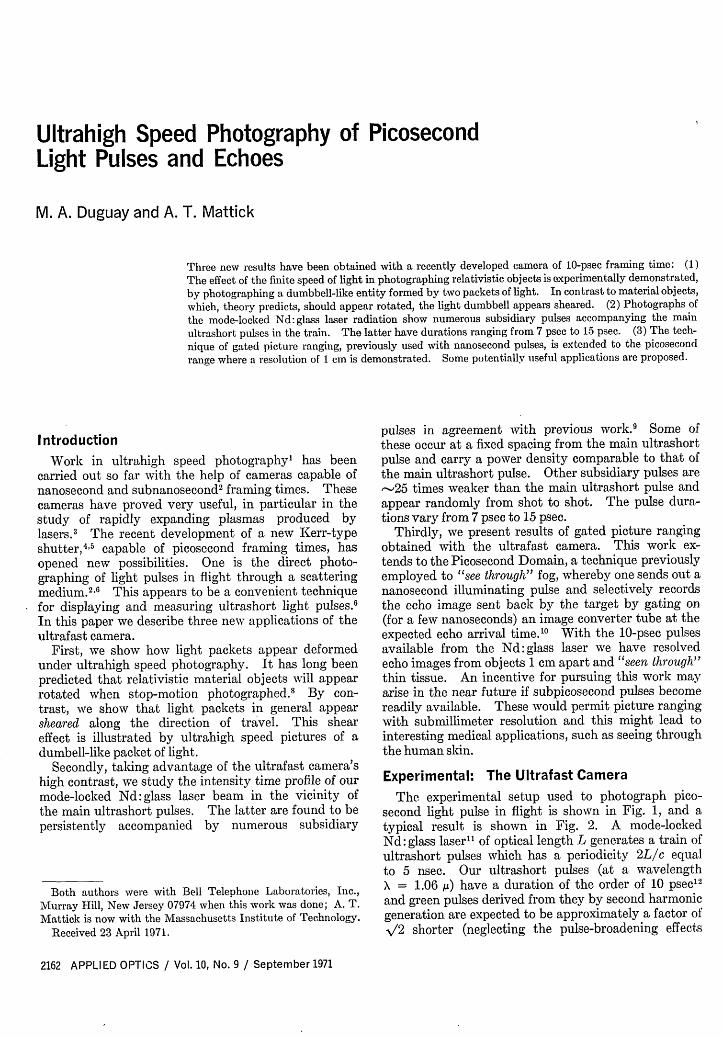
The 10 psec framing time camera makes similar ex-periments possible, but now on a scale where centi-metric resolution is possible. Figure 9 offers an ex-ample. There the green pulses are directed towardtwo glass slides where the explicit words front and backhave been inscribed. Since the echo images are sep-arated by 2 cm/c = 66 psec on their way to the ultra-fast camera, they can easily be resolved as shown inFig 9 by properly adjusting the optical delay line shownin Fig. 1.
The fact that the letters are in sharp focus in Fig. 9shows that the camera is optically excellent when gatedon. Our infrared beam which turns on the CS2 shutterdoes have considerable spatial inhomogeneities, butsince the shutter is at the lens, the optical imagingquality of the camera remains unaffected.
A possible application of the setup shown in Fig. 9is in computer memories. One can imagine a stackof glass or plastic plates on which information is re-corded conventionally or holographically. Each plate
Fig. 9. (a) Setup used to picture-range two glass slides on whichthe words front and back had been engraved. Camera setup is asin Fig. 1. (b) Each slide is selectively photographed by ad-
justing properly the delay line in Fig. 1.can be selected as in Fig. 9 by illuminating the stackfrom the front with a picosecond pulse and then gatingthe shutter at the right time to select the echo imagefrom the page desired.
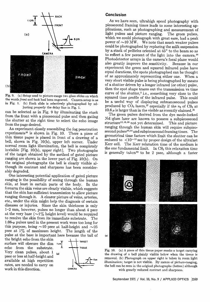
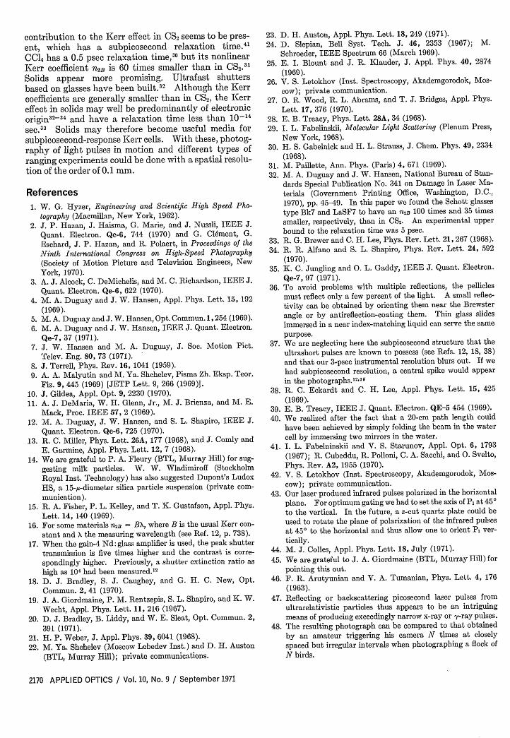
An experiment closely resembling the fog penetrationexperiments'0 is shown in Fig. 10. There a piece ofthin tissue paper is placed in front of a drawing of abell, shown in Fig. 10(b), upper left corner. Undernormal room light illumination, the bell is completelyinvisible [Fig. 10(b), upper right]. Two photographsof the target obtained by the method of gated pictureranging are shown in the lower part of Fig. 10(b). Onthe original photographs the bell is clearly visible al-though its contrast and sharpness has been consider-ably degraded.
One interesting potential application of gated pictureranging is the possibility of seeing through the humanskin, at least in certain parts of the body. In theforearm the skin veins are clearly visible, which suggeststhat the skin has sufficient transmission to allow pictureranging through it. A clearer picture of veins, arteries,etc., under the skin might help the diagnosis of certaindiseases or injuries. Since the skin thickness is only1-2 mm, however, pulses no longer than about 4 psecat the very base (-1% height level) would be requiredto resolve the skin from its immediate substrate. The1.06 -p pulses used in the present work were too long forthis purpose, being 10 psec at half-height and -25psec at 1% of maximum height. The length of thepulse at the base is important here because the tail ofthe bright echo from the skin TRlsurface will obscure the dim 1cm TAGET
echo from the substrate. ± TISSUE
Very clean pulses, about 1 (a)psec or less at half-height and \ savailable at high repetition j 6psrates, are needed to carry onwork in this direction. CAMERA
Conclusion
As we have seen, ultrahigh speed photography withpicosecond framing times leads to some interesting ap-plications, such as photographing and measurement oflight pulses and picture ranging. The green pulses,which we could photograph with great ease, had a peakpower of -10 MW. We note that much weaker pulsescould be photographed by replacing the milk suspensionby a stack of pellicles oriented at 450 to the beam so asto reflect a few percent of the light into the camera.36
Photodetector arrays in the camera's focal plane wouldalso greatly improve the sensitivity. Because in ourexperiment the green and squared infrared pulse haveequal durations, the spots photographed can be thoughtof as approximately representing either one. When avery short visible pulse is being photographed by meansof a shutter driven by a longer infrared (or other) pulse,then the spot shape traces out the transmission vs timecurve of the shutter,2 i.e., something very close to thesquared time profile of the infrared pulse. This couldbe a useful way of displaying subnanosecond pulsesproduced by CO2 lasers,27 especially if the n 2 of CS2 at10.6 g is larger than in the visible as recently claimed. "
The green pulses derived from the dye mode-lockedNd:glass laser are known to possess a subpicosecondstructure 2 8 38 not yet determined. This and pictureranging through the human skin will require subpico-second pulses3 9 44 and subpicosecond framing times. Thegeometrical time factors which limit the shutter can bereduced to <10-"3 sec by proper design of the ultrafastKerr cell. The Kerr relaxation time of the medium isthe one fundamental limit. In CS2 this relaxation timeis generally taken29 to be 2 psec, although a faster
(b)
Fig. 10. (a) A piece of thin tissue paper masks a target carryingthe drawing of a bell plainly visible below when the tissue isremoved. (b) Photograph on upper right is taken in room lightillumination; target is not visible. By means of picture-ranging,the bell can be seen in the original photographs (bottom) although
contribution to the Kerr effect in CS2 seems to be pres-ent, which has a subpicosecond relaxation time.4
CCl4 has a 0.5 psec relaxation time,30 but its nonlinearKerr coefficient n2B is 60 times smaller than in CS2.3'Solids appear more promising. Ultrafast shuttersbased on glasses have been built.3 2 Although the Kerrcoefficients are generally smaller than in CS2, the Kerreffect in solids may well be predominantly of electronicorigin32 -34 and have a relaxation time less than 10'-4sec.3 Solids may therefore become useful media forsubpicosecond-response Kerr cells. With these, photog-raphy of light pulses in motion and different types ofranging experiments could be done with a spatial resolu-tion of the order of 0.1 mm.
References
1. W. G. Hyzer, Engineering and Scientific High Speed P1-tography (Macmillan, New York, 1962).
2. J. P. Hazan, J. Haisma, G. Marie, and J. Nussli, IEEE J.Quant. Electron. Qe-6, 744 (1970) and G. Clement, G.Eschard, J. P. Hazan, and R. Polaert, in Proceedings of theNinth International Congress on High-Speed Photography(Society of Motion Picture and Television Engineers, NewYork, 1970).
3. A. J. Alcock, C. DeMichelis, and M. C. Richardson, IEEE J.Quant. Electron. Qe-6, 622 (1970).
4. M. A. Duguay and J. W. Hansen, Appl. Phys. Lett. 15, 192
(1969).5. M. A. Duguay and J. W. Hansen, Opt. Commun. 1,254 (1969).6. M. A. Duguay and J. W. Hansen, IEEE J. Quant. Electron.
Qe-7, 37 (1971).7. J. W. Hansen and M. A. Duguay, J. Soc. Motion Pict.
Telev. Eng. 80, 73 (1971).8. J. Terrell, Phys. Rev. 16, 1041 (1959).9. A. A. Malyutin and M. Ya. Shchelev, Pisma Zh. Eksp. Teor.
Fiz. 9, 445 (1969) [JETP Lett. 9, 266 (1969)].
10. J. Gildea, Appl. Opt. 9, 2230 (1970).11. A. J. DeMaria, W. H. Glenn, Jr., M. J. Brienza, and M. E.
Mack, Proc. IEEE 57, 2 (1969).12. M. A. Duguay, J. W. Hansen, and S. L. Shapiro, IEEE J.
Quant. Electron. Qe-6, 725 (1970).13. R. C. Miller, Phys. Lett. 26A, 177 (1968), and J. Comly and
E. Garmine, Appl. Phys. Lett. 12, 7 (1968).14. We are grateful to P. A. Fleury (BTL, Murray Hill) for sug-
gesting milk particles. W. W. Wladimiroff (StockholmRoyal Inst. Technology) has also suggested Dupont's LudoxHS, a 15-t-diameter silica particle suspension (private com-munication).
15. R. A. Fisher, P. L. Kelley, and T. K. Gustafson, Appl. Phys.Lett. 14, 140 (1969).
16. For some materials n2B = BX, where B is the usual Kerr con-
stant and X the measuring wavelength (see Ref. 12, p. 738).
17. When the gain-4 Nd: glass amplifier is used, the peak shuttertransmission is five times higher and the contrast is corre-spondingly higher. Previously, a shutter extinction ratio ashigh as 104 had been measured.12
18. D. J. Bradley, S. J. Caughey, and G. H. C. New, Opt.Commun. 2, 41 (1970).
19. J. A. Giordmaine, P. M. Rentzepis, S. L. Shapiro, and K. W.Wecht, Appl. Phys. Lett. 11, 216 (1967).
20. D. J. Bradley, B. Liddy, and W. E. Sleat, Opt. Commun. 2,391 (1971).
21. H. P. Weber, J. Appl. Phys. 39, 6041 (1968).
22. M. Ya. Shchelev (Moscow Lebedev Inst.) and D. H. Auston(BTL, Murray Hill); private communications.
23. D. H. Auston, Appl. Phys. Lett. 18, 249 (1971).24. D. Slepian, Bell Syst. Tech. J. 46, 2353 (1967); M.
Schroeder, IEEE Spectrum 66 (March 1969).25. E. I. Blount and J. R. Klauder, J. Appl. Phys. 40, 2874
(1969).26. V. S. Letokhov (Inst. Spectroscopy, Akademgorodok, Mos-
cow); private communication.27. 0. R. Wood, R. L. Abrams, and T. J. Bridges, Appl. Phys.
Lett. 17, 376 (1970).28. E. B. Treacy, Phys. Lett. 28A, 34 (1968).29. I. L. Fabelinskii, Molecular Light Scattering (Plenum Press,
New York, 1968).30. H. S. Gabelnick and H. L. Strauss, J. Chem. Phys. 49, 2334
(1968).31. M. Paillette, Ann. Phys. (Paris) 4, 671 (1969).32. M. A. Duguay and J. W. Hansen, National Bureau of Stan-
dards Special Publication No. 341 on Damage in Laser Ma-terials (Government Printing Office, Washington, D.C.,1970), pp. 45-49. In this paper we found the Schott glassestype Bk7 and LaSF7 to have an n2B 100 times and 35 timessmaller, respectively, than in CS2. An experimental upperbound to the relaxation time was 5 psec.
33. R. G. Brewer and C. H. Lee, Phys. Rev. Lett. 21, 267 (1968).34. R. R. Alfano and S. L. Shapiro, Phys. Rev. Lett. 24, 592
(1970).35. K. C. Jungling and 0. L. Gaddy, IEEE J. Quant. Electron.
Qe-7, 97 (1971).36. To avoid problems with multiple reflections, the pellicles
must reflect only a few percent of the light. A small reflec-tivity can be obtained by orienting them near the Brewsterangle or by antireflection-coating them. Thin glass slidesimmersed in a near index-matching liquid can serve the samepurpose.
37. We are neglecting here the subpicosecond structure that theultrashort pulses are known to possess (see Refs. 12, 18, 38)
and that our 3-psec instrumental resolution blurs out. If wehad subpicosecond resolution, a central spike would appearin the photographs.' 2 ' 3 9
38. R. C. Eckardt and C. H. Lee, Appl. Phys. Lett. 15, 425(1969).
39. E. B. Treacy, IEEE J. Quant. Electron. QE-5 454 (1969).40. We realized after the fact that a 20-cm path length could
have been achieved by simply folding the beam in the watercell by immersing two mirrors in the water.
41. I. L. Fabelninskii and V. S. Starunov, Appl. Opt. 6, 1793
(1967); R. Cubeddu, R. Polloni, C. A. Sacchi, and 0. Svelto,Phys. Rev. A2, 1955 (1970).
42. V. S. Letokhov (Inst. Spectroscopy, Akademgorodok, Mos-cow); private communication.
43. Our laser produced infrared pulses polarized in the horizontalplane. For optimum gating we had to set the axis of P, at 450to the vertical. In the future, a z-cut quartz plate could beused to rotate the plane of polarization of the infrared pulsesat 450 to the horizontal and thus allow one to orient P, ver-tically.
44. M. J. Colles, Appl. Phys. Lett. 18, July (1971).45. We are grateful to J. A. Giordmaine (BTL, Murray Hill) for
pointing this out.46. F. R. Arutyunian and V. A. Tumanian, Phys. Lett. 4, 176
(1963).47. Reflecting or backscattering picosecond laser pulses from
ultrarelativistic particles thus appears to be an intriguingmeans of producing exceedingly narrow x-ray or y-ray pulses.
48. The resulting photograph can be compared to that obtainedby an amateur triggering his camera N times at closelyspaced but irregular intervals when photographing a flock ofN birds.