Installation Manual 1 Ultrasonic Level Meter SLU It is highly recommended that the user carefully read all of the instructions in this manual before installation or use of the level meter for the first time. Keep the manual in a safe place. The manufacturer reserves the right to implement changes without prior notice.
Transcript
Installation Manual
1
Ultrasonic Level Meter SLU
It is highly recommended that the user carefully read all of the instructions in this manual before installation or use of the level meter for the first time. Keep the manual in a safe place. The manufacturer reserves the right to implement changes without prior notice.
2
Safety All operations described in this instruction manual should be carried out only by trained personnel or an accredited person. Warranty and post warranty service must be exclusively carried out by the manufacturer. Improper use, installation or set-up of the level meter can result in undesirable results (overfilling of the tank or damage of system components).The manufacturer is not responsible for improper use, losses of work caused by either direct or indirect damage, and for expenses incurred during installation or use of the level meter.
Measuring Principle
The SLU Ultrasonic level meters are compact measurement devices containing an ultasonic transmitter and an electronic module. The transducer generates ultrasonic pulses that travel at the speed of sound toward the target medium. These sound waves are reflected off the surface of the medium and are received by the transducer system. The “time of flight” between the transducer and the surface and then back to the transducer is measured. Based on the time period during which the individual pulses spread towards the level and back, this period is averaged by the electronics (that also performs temperature compensation) and subsequently are converted to an output current 4...20mA with HART protocol or ouput RS-485 Modbus and the measured value is displayed on the display.
The central processor evaluates and blocks out interfering signals, performs temperature compensation, compares the cleaned received signal with the false reflection map (e.g. from mixers, ladders, reinforcement etc.) and selects a suitable reflection (echo).
The SLU ultrasonic level meters are suitable for continuous non-contact level measurement of liquids (water, waste water sewage, etc.), mash and paste materials (sediments, resins etc.) in closed or open vessels, sumps, reservoirs and open channels. In the case of bulk-solid materials, the measuring range is reduced, but can be amplified or compensated by using the horn accessory.
Variant of Sensor
- SLU-02 - Measuring range from 0.15m - 2m plastic PVDF transmitter and plastic body (PP+HDPE), process connection with thread G 1"
- SLU-06 - Measuring range from 0.25m - 6m plastic PVDF transmitter and plastic body (PP+HDPE), process connection with thread G 1.1/2"
- SLU-10 - Measuring range from 0.4m - 10m plastic PVDF transmitter and plastic body (PP+HDPE), process connection with thread G 2.1/4"
- SLU-20 - Measuring range from 0.5m - 20m plastic PVDF transmitter and plastic body (PP+HDPE), aluminum alloy flange
Installation Manual
3
Dimensional Drawings
Variant SLU with protectivecable shield
Al alloy,DN100
Pg11 cable gland
ground terminal
Flange (for type 20) according to standard: DIN 2527, PN10
SLU02 SLU06
SLU10 SLU20
50
Installation Manual
Fig. 2: Level meter dead zone
m – Dead zone (blind zone, blocking distance)
-
Fig. 3: Installation distance from the tank wall
SLU–02 ; 10d > 1/12 c (min. 200 mm)
SLU–06d > 1/8 c (min. 200 mm)
SLU–20d > 1/10 c(min. 200 mm)
Fig. 4: Possible installation of the installation neck
a – Neck heightb – Neck widthm – Dead zone (blind zone, blocking dist.)
SLU–02 ; 06a < 3 bb > 100 mm
SLU–10a < 1.5 bb > 100 mm
SLU–20a < 1.5 bb > 150 mm
d – Distance from the tank wall
c – Maximum reach of the level meter
4
Installation Instructions
Install the level meter in the vertical position into the upper lid of the tank or vessel or reservoir using a the threaded connection, a fastening nut or a flange so that the level meter axis is perpendicular to the surface level of the measured liquid( Fig.1)
The min. dimensional parameters to install the level meter in to a lid or a celling of tank are givening (Fig.3)
When installing in an open channel (reservoir, drain etc.) install the level meter on to a bracket as close as possible to the expected max. level.
Each measuring range of SLU models has a specified ‘‘dead zone’. This means that within the first 10 to 50 centimers (depending on the model) below the transmitter, no signal reflected in this area can be evaluated. The dead zone (Fig.2) determines the min. distance possible between the level meter and the highest surface level. The min. distances to the medium are given in the chapter ‘Specifications’.
It is necessary to install the level meter so that the target level will not interfere with the dead zone when filled up to the maximum level. If the measured level interferes with the dead zone, the level meter will not work supply the correct output signal.
Fig.1 Recomended installation in the tank
d – Distance from the tank wall
c – Maximum reach of the level meter
If the maximum surface level in the tank interferes with the dead zone, the level mater has to be mounted higher within a neck extention to the tank. In this way, the tank can be filled to the maximum volume. The inner neck surface has to be even and smooth (without edges and welded points) the inner edge should be rounded where the ultrasonic wave eminates from the pipe. The neck diameter should be as large as possible but the neck height should be as low as possible, minimizing the extra distance between the medium and the sensor. Recommended dimensions of the extended neck are given in (Fig.4).
Installation Manual
Fig. 5: False echo from obstacles in the tank Fig. 6: False echo from the mixer paddle
Fig. 7: Level meter installation outside the influence of filling
Fig. 8: Level meter installation in silo or hopper
hornadapter
5
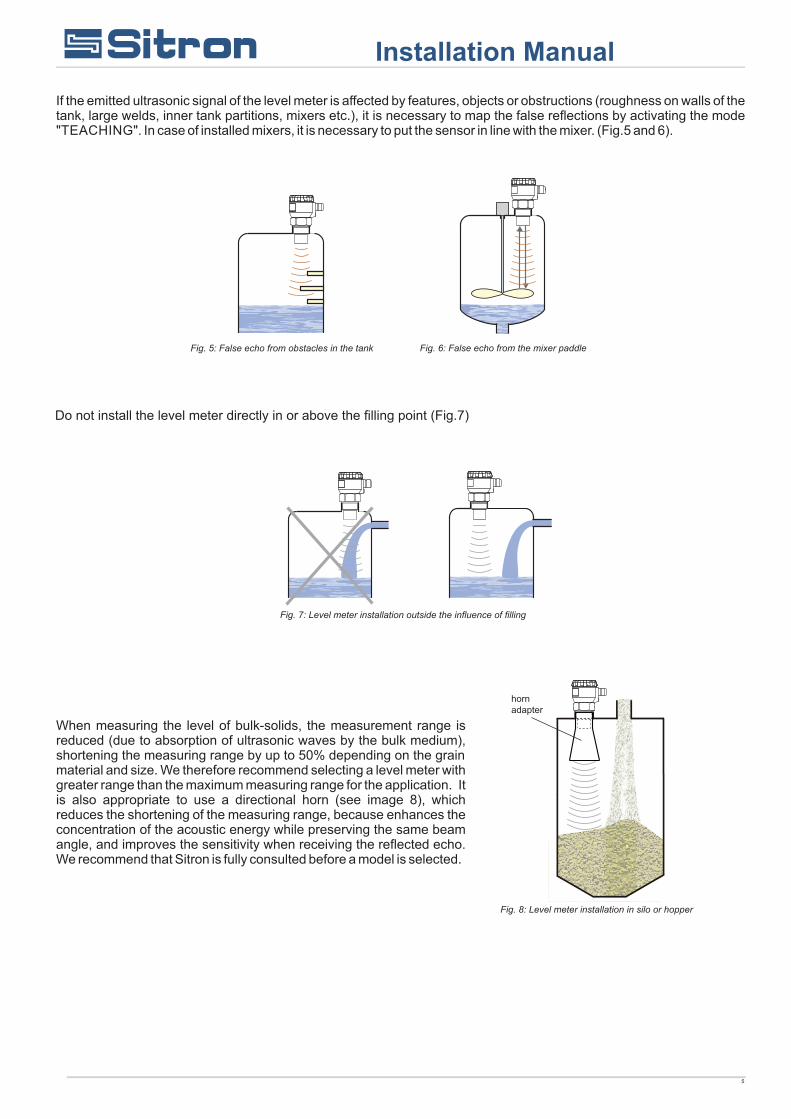
If the emitted ultrasonic signal of the level meter is affected by features, objects or obstructions (roughness on walls of the tank, large welds, inner tank partitions, mixers etc.), it is necessary to map the false reflections by activating the mode "TEACHING". In case of installed mixers, it is necessary to put the sensor in line with the mixer. (Fig.5 and 6).
Do not install the level meter directly in or above the filling point (Fig.7)
When measuring the level of bulk-solids, the measurement range is reduced (due to absorption of ultrasonic waves by the bulk medium), shortening the measuring range by up to 50% depending on the grain material and size. We therefore recommend selecting a level meter with greater range than the maximum measuring range for the application. It is also appropriate to use a directional horn (see image 8), which reduces the shortening of the measuring range, because enhances the concentration of the acoustic energy while preserving the same beam angle, and improves the sensitivity when receiving the reflected echo. We recommend that Sitron is fully consulted before a model is selected.
Installation Manual
!
!
Fig. 9: Foam on the surface
Fig. 10: Moderately stirred surface
Fig. 11: Intensely stirred surface
Obr. 12a: Short guide tube installation
ventilation holes
sleeves for mounting
Obr. 12b: Total guide tube installation
6
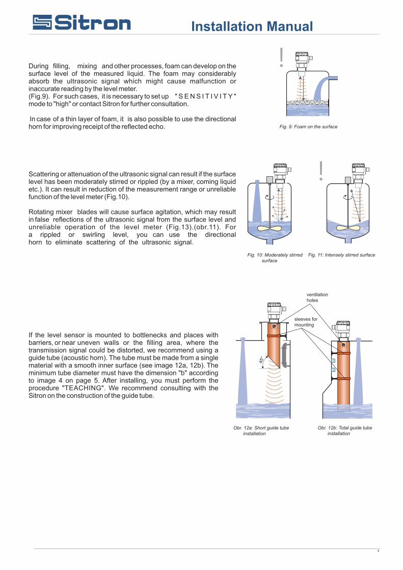
During filling, mixing and other processes, foam can develop on the surface level of the measured liquid. The foam may considerably absorb the ultrasonic signal which might cause malfunction or inaccurate reading by the level meter. (Fig.9). For such cases, it is necessary to set up " S E N S I T I V I T Y " mode to "high" or contact Sitron for further consultation. In case of a thin layer of foam, it is also possible to use the directional horn for improving receipt of the reflected echo.
Scattering or attenuation of the ultrasonic signal can result if the surface level has been moderately stirred or rippled (by a mixer, coming liquid etc.). It can result in reduction of the measurement range or unreliable function of the level meter (Fig.10).
Rotating mixer blades will cause surface agitation, which may result in false reflections of the ultrasonic signal from the surface level and unreliable operation of the level meter (Fig.13).(obr.11). For a rippled or swirling level, you can use the directional horn to eliminate scattering of the ultrasonic signal.
If the level sensor is mounted to bottlenecks and places with barriers, or near uneven walls or the filling area, where the transmission signal could be distorted, we recommend using a guide tube (acoustic horn). The tube must be made from a single material with a smooth inner surface (see image 12a, 12b). The minimum tube diameter must have the dimension "b" according to image 4 on page 5. After installing, you must perform the procedure "TEACHING". We recommend consulting with the Sitron on the construction of the guide tube.
Installation Manual
H + L = dead zone
Fig. 13: Solar radiation shielding cover
Fig. 14: Prevention to avoid intrusion of humidity
Fig. 15: Reflection board
7
The level meter must not be installed in places with direct solar radiation and must be protected against the effects of local weather.If installation in places with direct solar radiation is inevitable, it is necessary to mount a shielding cover above the level meter (Fig. 13). It is suitable to run the cable under a cable bushing (obliquely down in slack) according to Fig.14 to prevent penetration of humidity into the housing. In this way, rain and condensing water can flow off freely. The cable bushing and connector have to be sufficiently tightened to prevent penetration of humidity. To lower the minimum distance to the measured medium, a reflection board made from solid, even and smooth material can be installed to the level meter. Then the tank can be filled nearly up to the maximum height. This solution is suitable for open tanks and reservoirs (Fig. 15).
Installation Manual
8
display unit connector
Terminal block
metal clip
+ A B IS
ON
GND
120
display unit connector
Terminal block
metal clip
120Ω switch
Electrical Connections
The level meter is connected to the power supply or PLC or other control (evaluating) devices with a suitable cable with the outer diameter of 6 to 8mm using screw terminals located under the display module. The recommended cross section of cores for the current version 2 x 0.5 / 0.75 mm² and for the version with Modbus communication 2 x 2 x 0.25mm² (twisted pair, shielded). Plus pole (+U) is connected to the terminal (+), minus pole (0 V) to the terminal (-) and the shielding (only for shielded cables ) to the terminal ( ). Communication wires A and B of the line RS-485 ( for version M - Modbus) are connected to the terminal A and B.
Inside view of screw terminals of the level meter with currentoutput SLU(02/06/10/20)-C
Wiring diagram of the level meter with Modbus SLU(02/06/10/20)-M
Wiring diagram of the level meter with current output SLU(02/06/10/20)-C
Electrical connection must be done in de-energized state!The supply voltage source should preferably be realized as a stabilized power supply unit with safe voltage from 18 to 36 V DC (18 to 30 V DC for X version), which can be a part of the evaluation or display device.With case of strong electromagnetic interferences (EMI), parallel cable ducting with power lines, or when cable length exceeds 30 m we recommended the use of shielded cables.
Inside view of screw terminals of the level meter with ModbusSLU(02/06/10/20)-M
Procedure to connect the cable to the level meter:
1 - Unscrew the housing cover/ lid.
2 - Using your finger tips or finger nails, gently remove display by clutching the upper edge of the display module.
3 - If you cannot grasp the module, you can use a small screwdriver. Insert it as far as the seam allows so that it can be nudged upward as you work your way around the display from several sides. This will allow you to slightly lift the module.
4 - Release the cable outlet and thread the stripped supply cable in.
5 - Connect the cable to the screw terminals according to the diagram in Fig.17 or 18. Firmly tighten the terminals and the cable outlet.
6 - If the level meter with Modbus is involved as a terminal for RS-485, we recommend (to avoid reflections on the line) that the 120 ohms switch is activated. This is done by moving the small lever of the switch marked 120 ohms to the ON position. For level meters connected to the line RS-485 as an intermediate device (i.e. Slave), the termination resistors are not connected (switch remains off).
7- Insert the display module back into the head so that the connectors is properly connected. Be carefull that the position is correct or the terminal pins may be damaged.
8- Close the housing cover and then apply a PTFE or silicone tape seal to the threaded connection of the level meter body.
Now the level meter can be installed into the tank and wired back to the control unit or power supply. See safety not below.
Installation Manual
Fig. 17:
Fig. 18:
9
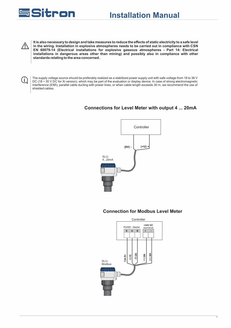
It is also necessary to design and take measures to reduce the effects of static electricity to a safe level in the wiring. Installation in explosive atmospheres needs to be carried out in compliance with CSN EN 60079-14 (Electrical installations for explosive gaseous atmospheres - Part 14: Electrical installations in dangerous areas other than mining) and possibly also in compliance with other standards relating to the area concerned .
The supply voltage source should be preferably realized as a stabilized power supply unit with safe voltage from 18 to 36 V DC (18 ÷ 30 V DC for Xi version), which may be part of the evaluation or display device. In case of strong electromagnetic interference (EMI), parallel cable ducting with power lines, or when cable length exceeds 30 m, we recommend the use of shielded cables.
Controller
SLU-4...20mA
SLU-Modbus
RS485 - Master
Connections for Level Meter with output 4 ... 20mA
Connection for Modbus Level Meter
Controller
Installation Manual
10
SIR420
Controller
SLU-C-X
Explosive area Non explosive area
Electrical connection for level meter in Classified Area
4...20mA
Galvanic separation of current signal from transducer in explosive area
Installation Manual
11
Set up elements
Status Signalization
Installation Manual
12
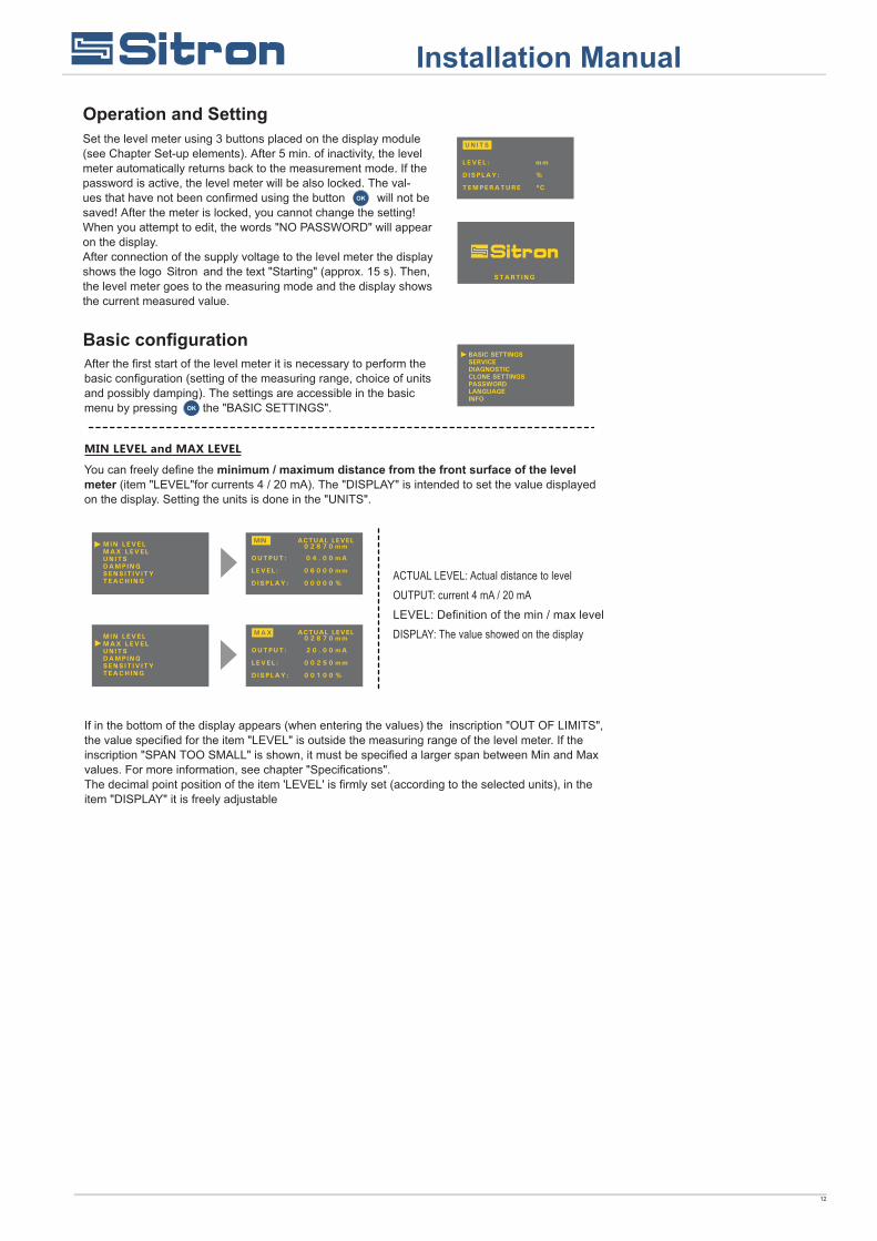
Basic configuration
Operation and Setting
Sitron
Installation Manual
13
Installation Manual
14
Installation Manual
15
Service settings
Installation Manual
TICS’’), the measuring accuracy will be reduced by around 1% of the set range. If
perature in the place of installation of the SLU (see mode, DIAGNOSTICS), it is ad-
16
This item is part of a menu with Modbus output level meter SLU-M. Modbus mode is intended for the settings of the level Modbus addresses, baud rate and parity settings.
Installation Manual
17
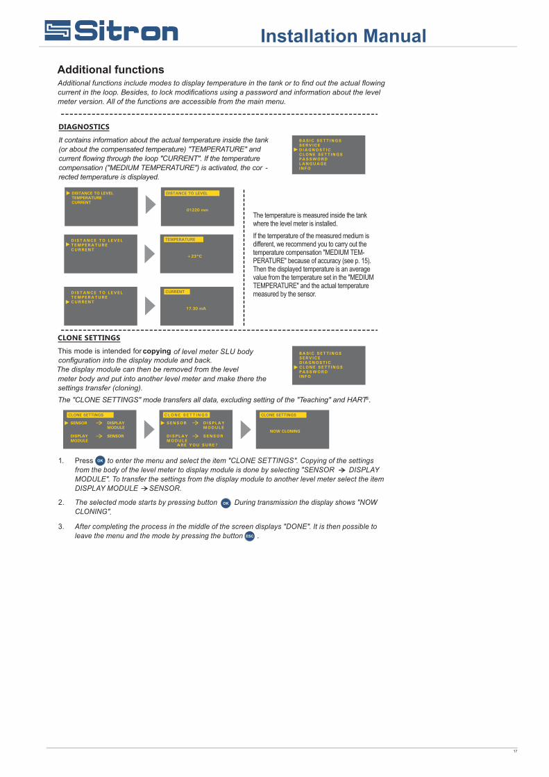
Additional functions
Installation Manual
of level meter SLU bodyconfiguration into the display module and back.
18
Installation Manual
Incompatible type of level meter. Transfer of the settings can be realized only with the same type of level meter (e.g. SLU-02 with SLU02, SLU-06 with SLU06) and with the firmware version 2.0 and later
The data set is not stored into the display module. The transfer can not be done. its necessary to repeat the procedure of the copying the settings in the mode CLONE SETTINGS.
19
Protocol HART
SLU
Protocol Modbus
Basic SCADA level, wich is freely available at the Sitron. Connectiong the level meter to a peripherial device can be performed using a converter SMC-485.
SLU-M
SMC-485
Installation Manual
SLU-XX
SLU
20
Safe, Protection, Compatibility and Explosion Proof The level meter SLU is equipped with protection against reverse polarity and output current overload Protection against dangerous contact is secured by low safety voltage compiles with EN 33 2000-4-41.Electromagnetic compatibility according to EN 55022/B, EN 61326/Z1 and EN 61000-4-2 to 6.Explosion proof of SLU-X type compiles with the following standards: EN 60079-0 : 2007;EN 60079-11 : 2007 ; EN 60079-26 : 2007
Special Conditions for Safe use SLU-X The device is designed for connection to the isolating repeater SIR-420. When the other opproved supply units is used, whose output parameters satisfy above mentioned output parameters, its is necessary to have a galvanic separation or, if supply unit without galvanic separation is used (Zener barriers), it is necessary provide potenital equalization between sensor and point of barrier earthing.For application in zone 0 the present explosive atmosphere- misture of air with flammable gases, vapour or mists must comply: 0,8 bar < p < 1,1 bar. The device must be installed in such a way, to prevent mechanical damage of sensor face.
The level meter does not require any personnel for its operation. It is used to inform the technological entity operating personnel on the measured substance level height during the operation. Maintenance of this equipment consists in verification of the integrity of the level meter and of the supply cable. Depending on the character of the substance measured, we recommend to verify at least once per year the clarity of the ultrasound transducer emitting field and to clean it, respectively. In case any visible defects are discovered, the manufacturer or reseller of this equipment must be contacted immediately.
It is forbidden to perform any modifications or interventions into the SLU level meter without manufacturer's approval. Potential repairs must be carried out by the manufacturer or by a manufacturer authorized service organization only. Installation, commissioning, operation and maintenance of the SLU level meter has to be carried out in accordance with this instruction manual; The provisions of regulations in force regarding the installation of electrical equipment have to be adhered to. In accordance with EN 60079-14 (Electrical apparatus for explosive gas atmospheres - Part 14: Electrical installations in hazardous areas other than mines) and in accordance with other standards that apply to given area.
Additional technical data for Ex proof - Max. internal values U=30V DC; I=132mA; P=0.99W C=370nF L=0.9mHi i i i i
Failure indication(echo loss, level in dead zone , internal failure)
Adjustable in modes:3.75mA; 22mA; Last measured value
PVC 2 x 0.75mm²PVC 2 x 2 x 0.25mm² (twisted pair, shielded)
Display module
Installation Manual
23
(according to EN 60079-10 and EN 60079-14)
SLU(02/06/10/20)-N Performance for non-explosive areas
SLU02-XSLU06-X
SLU10-X
SLU20-X
Area classification
Explosive proof - suitable for explosive areas (combustible gases or vapours) II 1/2G Ex ia IIB T5 Ga/Gb with isolation repeater (SIR-420), the whole level meter- zone 1, front head part - zone 0
Explosive proof - suitable for explosive areas (combustible gases or vapours) II 1/2G Ex ia IIA T5 Ga/Gb with isolation repeater (SIR-420), the whole level meter- zone 1, front head part - zone 0
Explosive proof - suitable for explosive areas (combustible gases or vapours) II 1/2G Ex ia IIA T5 Gb with isolation repeater (SIR-420), the whole level meter- zone 1
Sitron - BrasilR. Baronesa de Itu, 83
São Paulo - SP - 01231-001T.: (5511) 3825-2111F.: (5511) 3825-2171