24
Ultrasonic Thickness Gauge Instruction Manual
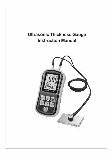
Ultrasonic Thickness Gauge
Instruction Manual

Contents
Before use
Operation instructions
Measurement tips-------------------------------(14)
Precautions for accuracy---------------------(17)
Maintain and warranty-------------------------(19)
Table of sound velocity------------------------(21)
Before measurement---------------------------------(06)
--------(08)
--------------------------------(09)
-------------------------------(10)
-(11)
-----------------------------------(13)
Thickness measurement---------------------
Sound measurement
Thickness alarm set-up
Thickness data storage/record/delete------------
Other features-------
Check-up-----------------------------------------------(01)
--------------------------------------------(02)
S ------------------------------------------- (03)
Diagram of the unit ------------------------------------(04)
Introduction
pecification
-01-
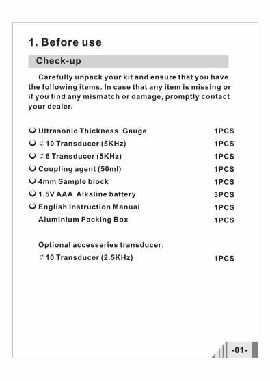
1PCS
1PCS
1PCS
1PCS
1PCS
3PCS
1PCS
1PCS
1PCS
Ultrasonic Thickness Gauge
¢10 Transducer (5KHz)
¢6 Transducer (5KHz)
Coupling agent (50ml)
4mm Sample block
1.5V AAA Alkaline battery
English Instruction Manual
Aluminium Packing Box
Optional accesseries transducer:
¢10 Transducer (2.5KHz)
Check-up
1. Before use
Carefully unpack your kit and ensure that you have
the following items. In case that any item is missing or
if you find any mismatch or damage, promptly contact
your dealer.
-02-
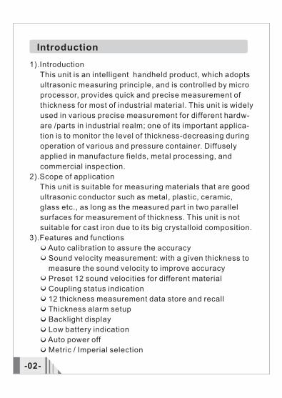
Introduction
1).Introduction
This unit is an intelligent handheld product, which adopts
ultrasonic measuring principle, and is controlled by micro
processor, provides quick and precise measurement of
thickness for most of industrial material. This unit is widely
used in various precise measurement for different hardw-
are /parts in industrial realm; one of its important applica-
tion is to monitor the level of thickness-decreasing during
operation of various and pressure container. Diffusely
applied in manufacture fields, metal processing, and
commercial inspection.
2).Scope of application
This unit is suitable for measuring materials that are good
ultrasonic conductor such as metal, plastic, ceramic,
glass etc., as long as the measured part in two parallel
surfaces for measurement of thickness. This unit is not
suitable for cast iron due to its big crystalloid composition.
3).Features and functions
Preset
Auto calibration to assure the accuracy
Sound velocity measurement: with a given thickness to
measure the sound velocity to improve accuracy
12 sound velocities for different material
Coupling status indication
12 thickness measurement data store and recall
Thickness alarm setup
Backlight display
Low battery indication
Auto power off
Metric / Imperial selection
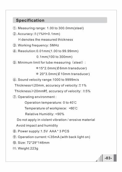
Specification
-03-
①. Measuring range: 1.00 to 300.0mm(steel)
②. Accuracy:±(1%H+0.1mm)
H denotes the measured thickness
③. Working frequency: 5MHz
④. Resolution:0.01mm(1.00 to 99.99mm)
0.1mm(100 to 300mm)
⑤. Minimum limit for tube measuring(steel):
Ф15*2.0mm(¢6mm transducer)
Ф 20*3.0mm(¢10mm transducer)
⑥. Sound velocity range:1000 to 9999m/s
Thickness≤20mm, accuracy of velocity:±1%
Thickness≥20mm时, accuracy of velocity: ±5%
⑦. Operating environment :
Operation temperature: 0 to 40℃
Temperature of workpiece: < 6 0 ℃
Relative Humidity: <90%
Do not apply in violent vibration / erosive material
Avoid impact and humidity
⑧. Power supply:1.5V AAA * 3 PCS
⑨. Operation current:≤35mA (with back light on)
⑩. Size: 72*29*146mm
⑾. Weight:223g
-04-
Ultrasonic Thickness Gauge
VELDEL
ALARMRECALL
ENTERCAL
INCH
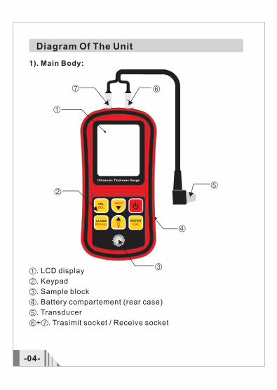
①. LCD display
②. Keypad
③. Sample block
④. Battery compartement (rear case)
⑤. Transducer
⑥+⑦. Trasimit socket / Receive socket
Diagram Of The Unit
1). Main Body:
①
②
③
④
⑤
⑥⑦

Control Panel
VELDEL
ALARMRECALL
ENTERCAL
INCH
VELDEL
ALARMRECALL
ENTERCAL
INCH
3).LCD display:
LCD display
①. Coupling indicator
②. Transducer Frequency
③. Back light icon
④. Battery power
⑤. Thickness unit
⑥. Sound velocity indicator
⑦. Thickness alarm
⑧. Sound velocity unit
⑨. Sound velocity reading
⑩. Velocity stored unit
⑾. Thickness reading
①
②
③ ④
⑤
⑥⑦
⑨
-05-
⑾
⑧
⑩
2). Keypad: -- ON/OFF -- Alarm set-up/Data recall -- Velocity set-up/ Select / delete Stored data -- Enter / Calibration -- Velocity / Thickness /Alarm adjust -- Velocity / Thickness / Alarm adjust , Backlight ON/OFF
-06-
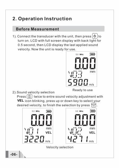
Before Measurement
Ready to use
VELDEL
ENTERCAL
Velocity selection
2. Operation Instruction
1). Connect the transducer with the unit, then press to
turn on. LCD with full screen display with back light for
0.5 second, then LCD display the last applied sound
velocity. Now the unit is ready for use.
2).Sound velocity selection
Press twice to entre sound velocity adjustment with
icon blinking, press up or down key to select your
desired velocity, to finish the selection by press .

-07-
ENTERCAL
VELDEL
ENTERCAL
3).Sound velocity adjustment
Press onece to entre velocity adjustment with stored
velocity unit blinking, press up or down key to adjust the
velocity to obtain desired value, then press to finish
the adjustment. The revised velocity will be saved into the
unit.
4).Calibration
On normal status, press for 3 second, then CAL
symbol shows in LCD with 5900 m/s velocity and 4.00 mm
display.
Use the standard sample block for calibration, until CAL
symbol disappeared, press up or down key to entre mea-
surement mode.
Ready to calibration Ready to use
After adjustmentBefore adjustment
-08-
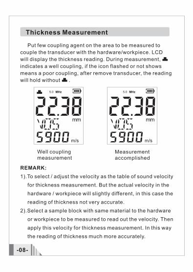
Thickness Measurement
Put few coupling agent on the area to be measured to
couple the transducer with the hardware/workpiece. LCD
will display the thickness reading. During measurement,
indicates a well coupling, if the icon flashed or not shows
means a poor coupling, after remove transducer, the reading
will hold without .
Well coupling measurement
REMARK:
1).To select / adjust the velocity as the table of sound velocity
for thickness measurement. But the actual velocity in the
hardware / workpiece will slightly different, in this case the
reading of thickness not very accurate.
2).Select a sample block with same material to the hardware
or workpiece to be measured to read out the velocity. Then
apply this velocity for thickness measurement. In this way
the reading of thickness much more accurately.
Measurement accomplished
-09-
Thickness measurement
Velocity measurement
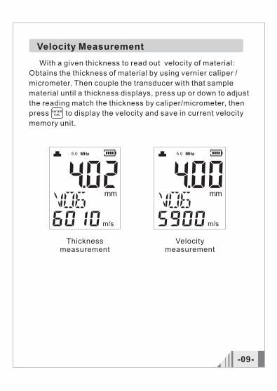
Velocity Measurement
ENTERCAL
Obtains the thickness of material by using vernier caliper /
micrometer. Then couple the transducer with that sample
material until a thickness displays, press up or down to adjust
the reading match the thickness by caliper/micrometer, then
press to display the velocity and save in current velocity
memory unit.
With a given thickness to read out velocity of material:
Thickness Alarm Set-up
ALARMRECALL
ENTERCAL
-10-
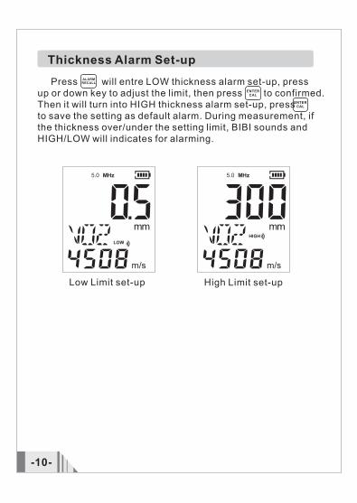
Press will entre LOW thickness alarm set-up, press up or down key to adjust the limit, then press to confirmed.Then it will turn into HIGH thickness alarm set-up, press to save the setting as default alarm. During measurement, ifthe thickness over/under the setting limit, BIBI sounds and HIGH/LOW will indicates for alarming.
Low Limit set-up High Limit set-up
ENTERCAL

ENTERCALThickness Data Storage/record/delete
ENTERCAL
ALARMRECALL
ENTERCAL
-11-
Memory fullData store
Data recall Vacant Memory
1). Thickness data storage During measurement, press once to save the thick-ness reading, if a FUL symbol show in the LCD that indicates the memory is full.
2). Store thickness data record
Press for 3 seconds to entre data record mode, press
up or down key to review M01 to M12 stored data.
If the memory unit is vacant, LCD will display ----, press
again turn to normal status.
VELDEL
VELDEL
-12-
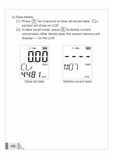
3).Data delete:
(1). Press for 3 second to clear all stored data,
symbol will show on LCD.
(2). In data recall mode, press to delete current
stored data. After delete data, the vacant memory will
display---- on the LCD.
Clear all data Delete current data
Other Features
INCH
-13-
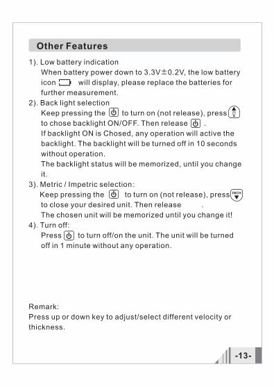
1). Low battery indication
When battery power down to 3.3V±0.2V, the low battery
icon will display, please replace the batteries for
further measurement.
2). Back light selection
Keep pressing the to turn on (not release), press
to chose backlight ON/OFF. Then release .
If backlight ON is Chosed, any operation will active the
backlight. The backlight will be turned off in 10 seconds
without operation.
The backlight status will be memorized, until you change
it.
3). Metric / Impetric selection:
Keep pressing the to turn on (not release), press
to close your desired unit. Then release .
The chosen unit will be memorized until you change it!
4). Turn off:
Press to turn off/on the unit. The unit will be turned
off in 1 minute without any operation.
Remark:
Press up or down key to adjust/select different velocity or
thickness.

-14-
3. Measurement tips
1). Cleaning surface
Before measuring, the dust, dirt, rusting and grease etc
that adheres on the hardware/workpiece must be removed
off and cleaned.
2). Decreasing the roughness of surface
Too rough surface may result in measure error/ fault
reading. Please try to make the surface smooth by milling,
polishing, filling or using high viscosity coupling agent.
3). Rough machining surface
The regular tiny texture/slots resulting form rough mach-
ining process may cause error, and the compensation
method is the same as in 3.2, adjusting the angle between
the crosstalk segregating board of the transducer a metal
membrane crossing the detector bottom centre and linear
texture/slots (parallel or vertically) may also get a better
result.
4). Measuring pipe and tubing
When measuring cylindrical parts to determine the thick-
ness of the pipe wall, orientation of the transducers is
important. If the diameter of the pipe is large than appro-
ximately 4 inches, measurements should be made with
the transducer oriented so that the gap in the wearface is
perpendicular (at right angle) to long axis of the pipe. For
smaller pipe diameters, two measurements should be
performed, one with the wearface gap perpendicular,
another with the gap parallel to the long axis of the pipe.
The smaller of the two displayed values should then be
taken as the thickness at that point.
5). Complex shape material
For complex shape material measurement, please refer
to the 3.4, the smaller of the two reading should then be
-15-
taken as the thickness.
6). Non-parallel surface
To get a satisfying ultrasonic response, the surface must
have its one measuring side parallel with another, other-
wise will obtain wrong result.
7). Influence of the material temperature
The size & sound velocity of material will change with the
temperature, when the precision is critical, please make
measurement in 2 samples of the material under the same
temperature to determine the proper reading resulting
from the temperature. When taking measurement for st-
eel parts in high temperature, this method may be adop-
ted to obtain the correct reading.
8). High acoustic reduction material
For materials in fiber, poriferous or big granular, acoustic
dispersion will cause the energy attenuation that may
result in abnormal readings(practically the reading less
than the actual thickness), in this case the material is not
suitable for the unit.
9). Reference sample block
For calibration for the gauge, a given thickness or sound
velocity of the material is very import. Calibration needs
at lest one referring standard sample block. This gauge
is provided with a 4.0mm sample block, please check for
calibration operations.
In different material & situation, only one sample block
may not satisfy every calibration. The more similar sample
block, the more exact reading obtained. Ideally, referring
block is a group of different thickness and same material,
-16-
by calibrating to the referring block, the effect of variation
of sound velocity will be minimized. To get the most exact
measure, a set of referring block is very important.
When measuring thin material which thickness close to
the minimum limit range of this unit, please use a referring
block to define exact limit of this material. Do not measu-
ring the material that the thickness under the minimum limit.
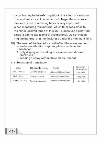
11). Selection of transducer
ITEM Characteristic RangeOperation temperature
10). The wear of the transducer will effect the measurement, when below situation happen, please replace the transducer: A. only display one reading when measured different thickness; B. reading display without take measurement.
General-purpose
Thin workpeice
General-purpose
1.00mm to 300.0mm(steel)
1.00mm to 50.0mm(steel)
1.00mm to 300.0mm(steel)
-10 to 60℃
-10 to 60℃
-10 to 60℃
5MHZ
5MHZ Φ6mm
2.5MHZ Φ10mm
Φ10mm
4. Precautions for accuracy
-17-
1). For very thin material Any ultrasonic thickness gauge, when the thickness of the material to be measured is less than the minimum limit the fault reading will occurs. Using sample block compare method to get a minimum limit of this material.2). For stained, rusting surface The stained/rusting surface on the contra side will occurs the ruleless wrong readings. Sometimes a small stained spot is hard to find out. Take care for measurement while measuring the known rusting spot/suspicious area. Or using sound insulation boardcelotex to locates the spot in different testing angles.3). Identify different velocity with vary material A fault reading would obtains, when measuring the hard- ware with the velocity calibrated by prior material. So a correct velocity should be adopted. The fault reading may also result form the difference between the actual velocity with the calibrated value. 4). Abrasion fo the transducer Because the transducer is made of propylene, long period use will cause the surface of transducer became more rough which will decline the sensitivity lead to the wrong reading. Please polish the surface with sand paper or whetstone to assure the smoothness and parallel. If the reading still unsteady, the transducer should be replaced with new one.5). ZERO function ZERO(calibration) is used to calibrate the unit with the standard block on the panel, do press this key for calibr- ation with other materials or will the wrong measuring will take place.6). Multilayer / composite material It is impossible to read out the thickness of the uncoupled multilayer for the ultrasonic wave can not go through the uncoupled space. Further more, the sonic wave cannot travel in the composite material at an even speed, so ult-

-18-
rasonic reflect principle cannot be applied to measure
the multilayer/composite material.
7). Influence from the oxidized surface
For some metals, such as aluminum a layer of oxide being
generated on their surface. The oxidized layer combined
with the substrate tightly, but the sonic wave travel within
2 different material which will lead to error reading, the
more oxidized layer the reading will be more tolerant.
Please calibrated the unit with the sample block that pick
up along the hardware to be measured, and obtain the
thick of sample block by using micrometer.
8). Abnormal reading
A seasoned operator should be capable to distinguish the
abnormal reading, practically result from rusting, erosive
recess surface / incorrect calibrate sample block/ the
inner flaw of material.
9). Choose and using coupling agent
Coupling agent serves the high frequency ultrasonic
wave transmitting between the transducer to the hardware.
Choose incorrect agent or wrong operation man cause
error or poor coupling which lead to failure of measuring.
The coupling agent should be used in proper way, typic-
cally, a single droplet of agent is sufficient.
It is important to use proper coupling agent, low viscosity
agent(the provided agent / machining oil) is suitable for
smooth surface. For rough / veritcal / aluminum surface,
high viscosity agent like glycerin and lubrication grease
is applicable. All kinds of coupling agent is available in
local market, you can buy it form local distributor as well.
5. Maintain And Warranty
-19-
1). Maintain
(1). Battery replacement
A).When low battery icon is showed, please replace the
batteries.
(A). Press to turn off.
(B). Open the battery door properly.
(C). Replace the low power batteries by new batteries.
B). When the gauge is not use for long period, please take
out the batteries.
2). Protection of transducer
Because the wear face of transducer is propylene mate-
rial which easy to be scratched. During taking measure-
ment on rough material, please using the transducer in
gentle motion. The temperature of the hardware should
not over 60℃, otherwise it will cause damage on the tra-
nsducer. Adhering oil, dust on the wear face will speed
up aging of transducer and lead to rupture. Clean the lead
-wire & transducer after use.
3). Cleaning the cabinet
Do not use solvent/alcohol for cleaning which erode the
cabinet & LCD window, brush and sweep only with a mo-
ist cotton cloth.
4). Cleaning the sample block
Because of coupling agent should be put on the sample
block during calibration, after use the sample block sho-
uld be cleaned for preventing rust. In higher temperature
environment, be sure protect the block form the droplet of
water. If the gauge is not use for a long period, please
apply some antirust on the sample block.
5). Avoid shocking/impact. Do not store the unit in high
humidity environment.
-20-
2. Warranty:
1).When the tolerance is over than stated in this manual,
please refer to the 3, 4, 5 chapter, in this manual.
2). Please contact us or distributor if the following occurs:
A. Component being destroyed, enable to measure.
B. Abnormal LCD display.
C. The tolerance is too big in proper operation.
D. Malfunction of keypad.
3). This gauge is a advanced technology product, the
repairing only by technician authorized by us, do not
try any alterations or repair attempts.
4). Warranty policy:
Please fill the warranty card with your cachet/chop after
purchasing this products, the warranty period for rep-
aired is 12 months form the date of original purchase.
During warranty period, product must be returned with
the invoice(copy) and warranty card to our customer
service department. The product will not be warranted
which without the warranty card.
Over warranty period, any repairing / maintenance will
charge the fee on the buyer in standard rate by local
distributor. The standard rate is not including the acc-
essories which not packing in standard package(For
example, abnormity transducer, lengthen lead-wire,
special software) .
We disclaims any liability due to: transportation dama-
ges; incorrect use or operation; manipulation, alterati-
ons or repair attempts; without warranty card, invoice.
5). Non-warranty list:
LCD, battery, probe, sample block, plastic case,
coupling agent

-21-
Sound velocity of common materials
Speific Declarations:
1).The product design and the manual updating, repairing
by technician authorized by us, do not try any alternations
or repair attempts.
2).Dispose of battery should in accordance with local laws
and regulations.
6. Table of sound velocity
Aluminum
Zinc
Silver
Glod
Tin
Iron/Steel
Brass
Copper
SUS
Acrylic resin
Water(20℃)
Glycerinl
soluble glass
2670
3530
4430
5440
5720
6310
6020
5630
5850
5660
6070
4650
2620
Acetate resin
Phosphor bronze
Turpentine
Glass
Incoloy alloy
Magnesium
Monel alloy
Nickle
Steel 4330(mild)
Steel 330
Titanium
Zirconium
Nylon
6320
4170
3600
3240
3230
5900
4640
4700
5790
2730
1480
1920
2350
Material Velocity(m/s) Material Velocity(m/s)

Version: 130-EN-0


