55
Ultrasound Boat Detection System A Worcester Polytechnic Institute Major Qualifying Project Advisor: Fabio Carrera Advisor: Peder Pedersen Students: Mark Johnson
| Date post: | 16-Dec-2015 |
| Category: |
Documents |
| Upload: | clayton-wilkey |
| View: | 217 times |
| Download: | 3 times |

Ultrasound Boat Detection System
A Worcester Polytechnic Institute
Major Qualifying Project
Advisor: Fabio Carrera
Advisor: Peder Pedersen
Students: Mark Johnson
Jonathan Lovisolo
Yasuhiro Okuno

Presentation Overview
System Block DiagramReal Environment
• Object Detection• Boat Detection• Multiplexing (MUX)
Software Environment• Signal Processing• Intelligent System• Logging
Presentation Overview
Development StagesStage 1: Lab EnvironmentStage 2: Portable SystemStage 3: Real Environment
Future ImprovementsWake Height DetectionPressure Sensing

Bo
at
Bo
at
P/R
MUX
Real Environment
SignalProcessing
Intelligent System
Echo signal
Logging System
•Echo• Signal: TRUE• Delay: 2 (ms)• Strength: 92• Width: 96.2 (us)
• Boat detected at:2003-7-15-11:23:42
• Speed of boat: 14.1 (km/h)
• Length:6.3 (m)
Data after Signal Processing Logged data
System Level Block Diagram
Software Environment on System
MUX: MultiplexerP/R: Pulser/Receiver

Real Environment Design
The following slides will depict the system’s operation in the canal setting, including:
Boat DetectionTransducer Multiplexing
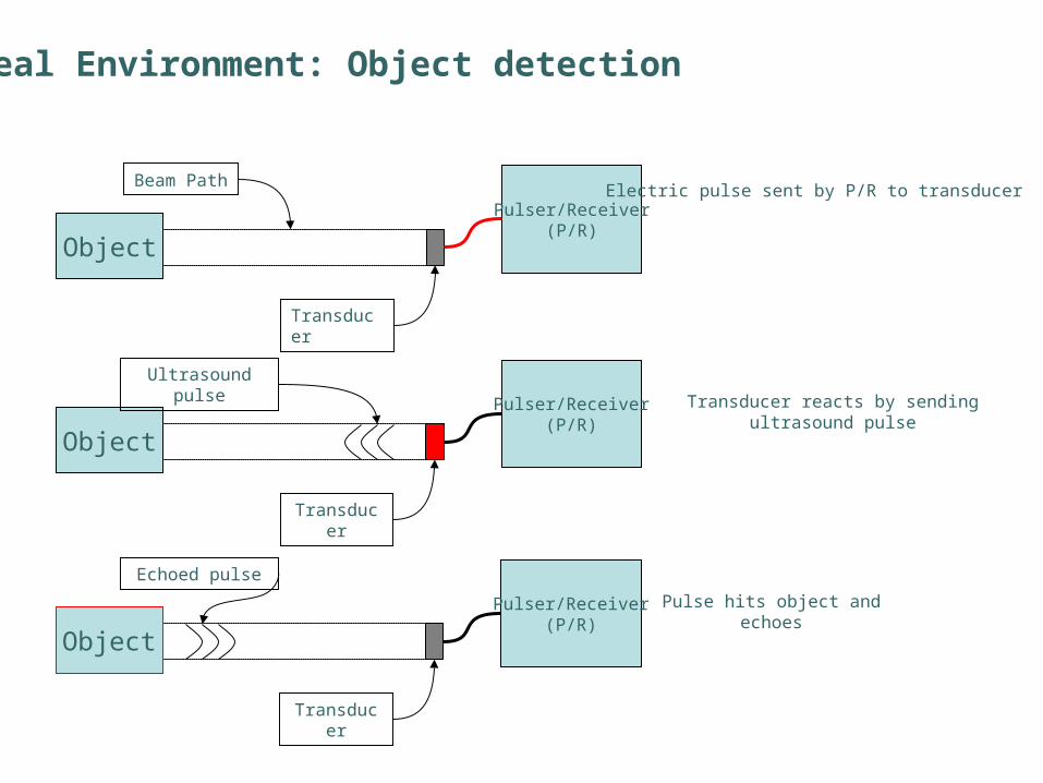
Object
Pulser/Receiver(P/R)
Beam Path
Transducer
Electric pulse sent by P/R to transducer
Object
Pulser/Receiver(P/R)
Ultrasound pulse
Transducer
Transducer reacts by sending ultrasound pulse
Object
Pulser/Receiver(P/R)
Echoed pulse
Transducer
Pulse hits object and echoes
Real Environment: Object detection

Object
Pulser/Receiver(P/R)
Echoed pulse
Transducer
Echo reaches transducerThe transducer turns echo into electric pulse and sends it to P/R
Pulser/Receiver(P/R)
Transducer
Electric pulse sent to the signal processing unit
Signal Processing unit
Real Environment: Object detection
Boat
Boat
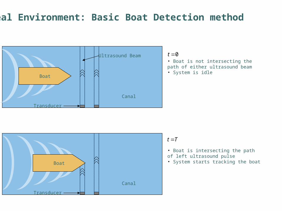
Ultrasound Beam
Canal
Canal
Transducer
Transducer
• Boat is not intersecting the path of either ultrasound beam• System is idle
• Boat is intersecting the path of left ultrasound pulse• System starts tracking the boat
0t
Tt
Real Environment: Basic Boat Detection method

Canal
Transducer
• Boat just cleared off of the left ultrasound pulse• A boat just passed by!• Length of the boat can be calculated by:Boat
2Tt
)/()()( 2 smvsml boatboat
Canal
Transducer
• Boat is intersecting the path of both ultrasound pulses• Calculate speed of the boat:Boat
1Tt
rs transduceobetween tw distance:
)()()/(
1
d
smdsmvboat
d
Real Environment: Basic Boat Detection method

Multiplexer
Switch signal from PC
Pulser/Receiver(P/R)
Connected to P/R
Disconnected from P/R
After receiving one switch signal from PC
Multiplexer
Switch signal from PC
Pulser/Receiver(P/R)
Disconnected from P/R
Connected to P/R
Multiplexer Allows one P/R to alternately read from 2 transducers
Real Environment: Multiplexer

Boat
Real Environment: To the next step
Time
Echo from transducer A Echo from transducer AEcho from transducer B
The signals received from the transducer by the pulser receiver are sent to the PC in the form of Electrical signals to be processed by Signal Processing Unit
Multiplexer
Switch signal from PC
Pulser/Receiver(P/R)
Transducer A
Transducer B
Software Environment
The following slides will describe the software used in this system including the:
Signal ProcessingIntelligent SystemLogging System

Signal Processing
This begins the outline of the Signal Processing Section

Ultrasound pulses such as this are sent into the canal from the transducer
Ultrasound pulses such as this are sent into the canal from the transducer
Multiple PulsesMultiple Pulses
Individual PulseIndividual Pulse
Transducer System
Transducer System

When the pulses strike an object, echoes are reflected back towards the transducer.
When the pulses strike an object, echoes are reflected back towards the transducer.
TransducerTransducer TransducerTransducer
Pulses TransmittedPulses Transmitted Pulses ReturningPulses Returning
Water Water
Side Of
Boat
Side Of
BoatSide Of
Boat
Side Of
Boat
Canal Wall
Canal Wall
Canal Wall
Canal Wall

If this pulse is sent:
The returning echo will look the same:

Canal Wall
Transducer System
Transmitted Into Canal
Transmitted Into Canal
Returning From Canal
Returning From Canal
PulsesPulses
This is a possible setup of the transducer system
This is a possible setup of the transducer system

Canal Wall
Transducer System
Transmitted Into Canal
Transmitted Into Canal
Returning From Canal
Returning From Canal
PulsesPulses
This represents what is being transmitted into the canal
This represents what is being transmitted into the canal

Canal Wall
Transducer System
Transmitted Into Canal
Transmitted Into Canal
Returning From Canal
Returning From Canal
PulsesPulses
This represents what is being reflected from the canal
This represents what is being reflected from the canal

Canal Wall
Transducer System
Transmitted Into Canal
Transmitted Into Canal
Returning From Canal
Returning From Canal
PulsesPulses
When the canal is empty, there is nothing for the pulses to reflect off of. Thus, the return is empty
When the canal is empty, there is nothing for the pulses to reflect off of. Thus, the return is empty

Canal Wall
Transducer System
Transmitted Into Canal
Transmitted Into Canal
Returning From Canal
Returning From Canal
EchoesEchoes
When a boat travels in front of the transducer system, echoes begin returning.When a boat travels in front of the transducer system, echoes begin returning.

Canal Wall
Transducer System
Transmitted Into Canal
Transmitted Into Canal
Returning From Canal
Returning From Canal
EchoesEchoes
As the boat continues to pass, more and more echoes are recordedAs the boat continues to pass, more and more echoes are recorded

Canal Wall
Transducer System
Transmitted Into Canal
Transmitted Into Canal
PulsesPulses
When the boat passes, the transducer system stops receiving echoes.
When the boat passes, the transducer system stops receiving echoes.
Returning From Canal
Returning From Canal

At this point, the system has recorded a series of echoes, such as this:
At this point, the system has recorded a series of echoes, such as this:

When we receive an echo, we are measuring its:When we receive an echo, we are measuring its:
Presence
Is there an echo or not?
Is there an echo or not?

When we receive an echo, we are measuring its:When we receive an echo, we are measuring its:
Signal Width
How wide the echo is
How wide the echo is

When we receive an echo, we are measuring its:When we receive an echo, we are measuring its:
Amplitude
The maximum strength of the
signal
The maximum strength of the
signal

When we receive an echo, we are measuring its:When we receive an echo, we are measuring its:
Time Delay
Time spent traveling in the
water
Time spent traveling in the
water

Correlation
How much the echo resembles the original pulse
How much the echo resembles the original pulse
This graph represents the output of the correlation function, a complex signal processing algorithm. The height of the solid line represents the similarity between pulse and echo. The higher the line, the more resemblance that exists.
When we receive an echo, we are measuring its:When we receive an echo, we are measuring its:

PresencePresence
AmplitudeAmplitude
Time DelayTime Delay
Once these four characteristics have been measured, Echo Validity can be determinedOnce these four characteristics have been measured, Echo Validity can be determined
CorrelationCorrelation
Echo ValidityEcho Validity

Echo Validity determines if the pulse sent out is the same as the echo received.
Echo Validity determines if the pulse sent out is the same as the echo received.
Pulse Echo Received
Same?
In this case, the echo received is the same as the pulse transmitted. Thus, echo validity is high.
Echo Validity

Echo Validity determines if the pulse sent out is the same as the echo received.
Echo Validity determines if the pulse sent out is the same as the echo received.
Pulse Echo Received
In this case, the echo received is dissimilar from the pulse sent out. Thus, the echo validity is very low.
Same?
Echo Validity

Echoes from the canal will only have a high validity if they are reflected off of a boat’s
smooth, hard sides.
Echoes with low validity correlate to reflections off of debris, birds, etc.
If there is no echo, the echo validity is 0.

Echo ReceivedEcho Received Validity Measurement
Validity Measurement
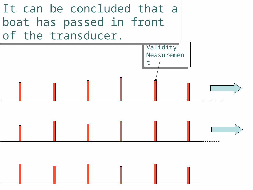
Thus, if a string of echoes is received, all with high validity,Thus, if a string of echoes is received, all with high validity,
Validity Measurement
Validity Measurement
It can be concluded that a boat has passed in front of the transducer.It can be concluded that a boat has passed in front of the transducer.

Validity Measurement
Validity Measurement
If the echo validity is low, no boat has passed yet.If the echo validity is low, no boat has passed yet.

Intelligent System & Logging
The following slides will depict the Intelligent System design used to gather information about the boats, as well as how that information is logged
The intelligent system then takes the signal data and makes final determinations on the
presence of a boat.
It looks at how many valid echoes are received consecutively with similar time delays.
If there are enough valid echoes then a boat has passed.

Validity Measurement
Validity Measurement
There are enough valid echoes here. Therefore there is a boatThere are enough valid echoes here. Therefore there is a boat

Validity Measurement
Validity Measurement
This only has a few valid echoes. This was probably not a boat.This only has a few valid echoes. This was probably not a boat.

Because debris, bubbles, or other factors can affect a signal we need to make the system
allow for some invalid echoes.
If a there is one invalid echo amidst a string of valid echoes we ignore it and go on.

Validity Measurement
Validity Measurement
Single bad echoes can be ignored. They could be caused by interference.Single bad echoes can be ignored. They could be caused by interference.
Bad EchoBad Echo

If signals return with very different time delays then they are probably reflecting off of different
boats.
The system uses the time delay as a means of distinguishing between boats in the canal.

Echo 1Echo 1
Echo 2Echo 2
The two echoes had different delays because they hit different boats.The two echoes had different delays because they hit different boats.
Time delay
Time delay

The system sends pulses every 0.01 seconds. The system can keep track of how many
pulses happen between when the boat hits Transducer A and Transducer B.
The number of pulses tells the system how much time it took a boat to move a fixed distance. From this information we can
calculate the speed of the boat. This was depicted earlier.

Boat
Boat
Ultrasound Beam
Canal
Canal
Transducer
Transducer
• Boat is not intersecting the path of either ultrasound beam• System is idle
• Boat is intersecting the path of left ultrasound pulse• System starts tracking the boat
0t
Tt
Real Environment: Basic Boat Detection method

Canal
Transducer
• Boat just cleared off of the left ultrasound pulse• A boat just passed by!• Length of the boat can be calculated by:Boat
2Tt
)/()()( 2 smvsml boatboat
Canal
Transducer
• Boat is intersecting the path of both ultrasound pulses• Calculate speed of the boat:Boat
1Tt
rs transduceobetween tw distance:
)()()/(
1
d
smdsmvboat
d
Real Environment: Basic Boat Detection method

When the system stops receiving valid echoes from a boat the speed is calculated. This was
also shown earlier.
Once this happens the information for the boat is logged. This information is printed in the log
file like this:Timestamp: Sun Feb 16 14:30:07 2003 Speed: 9.7 km/h Length: 2.8 mNote: The length of this boat may be inaccurate due to other boats in the system!
The note is shown when another boat interferes with the data for this boat.

Once the data is logged to a file it can be retrieved at any time. The system will be
capable of retrieval by either disk or remotely through the internet when it is complete.

Development Process
The next few slides will depict the development process of this project
By the end of the academic year, this group will have completed the second stage of development, ready for testing in Venice.

Digitizer(LeCroy9400)
GPIB
Fish Tank Pulser/Receiver
PC with test software
First Generation
Test of Theory in lab controlled environment•Test that the method works•Refine method of detection and data collection•Establish a detection software
Toy Boat
Development Stages: First Generation

Laptopwith digitizer cardand test softwareTest Object
(i.e. real boat)
Pool Pulser/Receiver
Second Generation
Field testing•Test theory established in first generation•Deal with any irregularity of the real environment•Finalize detection and data collection software
Development Stages: Second Generation

Venice Canals Pulser/Receiver
Final Generation
Deployment•Implement all functionality developed in 2nd generation in a single standalone system.•Test all functionality in field•Deploy system for usage in Venice canals
StandaloneEmbedded
System
Boat
Research Team
Data TransferVia Network
orRemovable Media
Development Stages: Third Generation

Lateral Wave Force
Wake Height
Boat
Accelerometer or Pressure
Transducer
In the Future…• Use Accelerometer or Pressure Transducer to measure force exerted on the wall.
• This data can be used to relate traffic and canal damage
Future Improvements: Wake height and pressure detection
Time Boat Type Wake height (cm) Pressure (?)* Speed (km/h) Length (m)
2003-7-15-11:23:42 Motor-boat C 35.5 23 14.3 6.1
2003-7-15-11:24:32 Gondola A 9.3 10 6.2 5.5
2003-7-15-11:25:35 Freight D 11.6 18 8 8.2
With all the information, the log may look like the following for each station:(note: the values in the table is a sample and may not resemble real data)
* The pressure measurement unit is unknown at the point of this writing, and the values may be unreasonably off

Conclusions
The project is currently in the second phase of development.
The second phase will be completed by May 2003, ready for testing in Venice
The system will be able to log: Boat Traffic Speed of Boats Boat Size


