Ultrasound generation with high power and coil only EMAT concepts Dirk Rueter ⇑ , Tino Morgenstern University of Applied Sciences Ruhr West, 45473 Muelheim, Germany article info Article history: Received 12 February 2014 Received in revised form 22 May 2014 Accepted 17 June 2014 Available online 3 July 2014 Keywords: EMAT Pulsed power Non-linear effects Spark induced ultrasound Laser induced ultrasound abstract Electro-magnetic acoustic transducers (EMATs) are intended as non-contact and non-destructive ultra- sound transducers for metallic material. The transmitted intensities from EMATS are modest, particularly at notable lift off distances. Some time ago a concept for a ‘‘coil only EMAT’’ was presented, without static magnetic field. In this contribution, such compact ‘‘coil only EMATs’’ with effective areas of 1–5 cm 2 were driven to excessive power levels at MHz frequencies, using pulsed power technologies. RF induction cur- rents of 10 kA and tens of Megawatts are applied. With increasing power the electroacoustic conversion efficiency also increases. The total effect is of second order or quadratic, therefore non-linear and progres- sive, and yields strong ultrasound signals up to kW/cm 2 at MHz frequencies in the metal. Even at consid- erable lift off distances (cm) the ultrasound can be readily detected. Test materials are aluminum, ferromagnetic steel and stainless steel (non-ferromagnetic). Thereby, most metal types are represented. The technique is compared experimentally with other non-contact methods: laser pulse induced ultra- sound and spark induced ultrasound, both damaging to the test object’s surface. At small lift off distances, the intensity from this EMAT concept clearly outperforms the laser pulses or heavy spark impacts. Ó 2014 The Authors. Published by Elsevier B.V. This is an open access article under the CC BY-NC-ND license (http://creativecommons.org/licenses/by-nc-nd/3.0/). 1. Introduction Conventional electromagnetic acoustical transducers (EMATs) include a permanent magnet and an induction coil. The coil induces RF eddy currents into a metallic test object. The RF eddy currents and the presence of the permanent field B 0 result in oscil- lating Lorentz forces, i.e., ultrasound excitation in the metal. The method excites metallic test objects over some distance via imma- terial magnetic fields. As an appreciated feature, this magnetic ultrasound transduction readily permeates most non-metallic bar- riers (air, oxides, oil, painting, humidity, packaging material: paper, plastic foil, etc.). A variety of possible geometries and ultrasound modes (shear waves, longitudinal waves, etc.) can be applied. As a fundamental problem, the transmitted ultrasound intensities from EMATs are modest. Usually, only very small ‘‘lift off’’ dis- tances in the range of less than few mm are practical for proper EMAT operation. On the other hand, many application fields – like heavy steel industries or prepackaged metal parts – would appre- ciate increased lift off distances or higher ultrasound intensities for crude and large test objects. Additionally, permanent magnetic fields from conventional EMATs attract ferromagnetic particles. Such adhering particles potentially disturb the measurement or even may cause mechanical damage to the transducer or the test object. Some recent EMAT types utilize pulsed electromagnets for B 0 , thereby avoiding that problem (Refs. [1–4]). In this contribution ‘‘coil only EMATs’’ are investigated, i.e., a permanent magnetic field is lacking. Instead, the RF induction field itself interacts with excited (and orthogonal) eddy currents in the test object, producing Lorentz forces and acoustic pressure in the sample. This concept was already investigated by Jian et al. (Refs. [5,6]). The authors modeled and experimentally verified (Ref. [5]) the ultrasound emission from two different EMAT systems (spiral coil and line coil). Lorentz forces and displacements in the test metal resulted from eddy current and a permanent (static) field B 0 and additionally – of particular interest here – from eddy cur- rent and the RF induction field itself (i.e., the dynamic field). With 0.1 mm lift-off, a static field B 0 = 0.395 T and a characteristic exci- tation frequency around 300 kHz the authors found (cited literally from Ref. [5]) ‘‘the force due to the dynamic field is about five times larger than the Lorentz force due to the applied static magnetic of 0.395 T’’. This remark is very interesting, since the permanent field B 0 in conventional EMATs cannot be easily increased by a factor of five: for Ref. [5] this would be a quite challenging 2 T and that is currently not possible with conventional magnet materials. EMAT schemes without a static field were also mentioned in even older textbooks (e.g., Ref. [7]). Herein, the occurring Lorentz forces are recognized to be exclusively repulsive, they increase with the square of excitation current and they oscillate with a http://dx.doi.org/10.1016/j.ultras.2014.06.012 0041-624X/Ó 2014 The Authors. Published by Elsevier B.V. This is an open access article under the CC BY-NC-ND license (http://creativecommons.org/licenses/by-nc-nd/3.0/). ⇑ Corresponding author. Tel.: +49 1606321020. E-mail addresses: [email protected](D. Rueter), Tino.morgen- [email protected](T. Morgenstern). Ultrasonics 54 (2014) 2141–2150 Contents lists available at ScienceDirect Ultrasonics journal homepage: www.elsevier.com/locate/ultras
Transcript
Ultrasonics 54 (2014) 2141–2150
Contents lists available at ScienceDirect
Ultrasonics
journal homepage: www.elsevier .com/locate /ul t ras
Ultrasound generation with high power and coil only EMAT concepts
http://dx.doi.org/10.1016/j.ultras.2014.06.0120041-624X/� 2014 The Authors. Published by Elsevier B.V.This is an open access article under the CC BY-NC-ND license (http://creativecommons.org/licenses/by-nc-nd/3.0/).
Electro-magnetic acoustic transducers (EMATs) are intended as non-contact and non-destructive ultra-sound transducers for metallic material. The transmitted intensities from EMATS are modest, particularlyat notable lift off distances. Some time ago a concept for a ‘‘coil only EMAT’’ was presented, without staticmagnetic field. In this contribution, such compact ‘‘coil only EMATs’’ with effective areas of 1–5 cm2 weredriven to excessive power levels at MHz frequencies, using pulsed power technologies. RF induction cur-rents of 10 kA and tens of Megawatts are applied. With increasing power the electroacoustic conversionefficiency also increases. The total effect is of second order or quadratic, therefore non-linear and progres-sive, and yields strong ultrasound signals up to kW/cm2 at MHz frequencies in the metal. Even at consid-erable lift off distances (cm) the ultrasound can be readily detected. Test materials are aluminum,ferromagnetic steel and stainless steel (non-ferromagnetic). Thereby, most metal types are represented.The technique is compared experimentally with other non-contact methods: laser pulse induced ultra-sound and spark induced ultrasound, both damaging to the test object’s surface. At small lift off distances,the intensity from this EMAT concept clearly outperforms the laser pulses or heavy spark impacts.
� 2014 The Authors. Published by Elsevier B.V. This is an open access article under the CC BY-NC-NDlicense (http://creativecommons.org/licenses/by-nc-nd/3.0/).
1. Introduction
Conventional electromagnetic acoustical transducers (EMATs)include a permanent magnet and an induction coil. The coilinduces RF eddy currents into a metallic test object. The RF eddycurrents and the presence of the permanent field B0 result in oscil-lating Lorentz forces, i.e., ultrasound excitation in the metal. Themethod excites metallic test objects over some distance via imma-terial magnetic fields. As an appreciated feature, this magneticultrasound transduction readily permeates most non-metallic bar-riers (air, oxides, oil, painting, humidity, packaging material: paper,plastic foil, etc.). A variety of possible geometries and ultrasoundmodes (shear waves, longitudinal waves, etc.) can be applied. Asa fundamental problem, the transmitted ultrasound intensitiesfrom EMATs are modest. Usually, only very small ‘‘lift off’’ dis-tances in the range of less than few mm are practical for properEMAT operation. On the other hand, many application fields – likeheavy steel industries or prepackaged metal parts – would appre-ciate increased lift off distances or higher ultrasound intensities forcrude and large test objects. Additionally, permanent magneticfields from conventional EMATs attract ferromagnetic particles.Such adhering particles potentially disturb the measurement or
even may cause mechanical damage to the transducer or the testobject. Some recent EMAT types utilize pulsed electromagnets forB0, thereby avoiding that problem (Refs. [1–4]).
In this contribution ‘‘coil only EMATs’’ are investigated, i.e., apermanent magnetic field is lacking. Instead, the RF induction fielditself interacts with excited (and orthogonal) eddy currents in thetest object, producing Lorentz forces and acoustic pressure in thesample. This concept was already investigated by Jian et al. (Refs.[5,6]). The authors modeled and experimentally verified (Ref. [5])the ultrasound emission from two different EMAT systems (spiralcoil and line coil). Lorentz forces and displacements in the testmetal resulted from eddy current and a permanent (static) fieldB0 and additionally – of particular interest here – from eddy cur-rent and the RF induction field itself (i.e., the dynamic field). With0.1 mm lift-off, a static field B0 = 0.395 T and a characteristic exci-tation frequency around 300 kHz the authors found (cited literallyfrom Ref. [5]) ‘‘the force due to the dynamic field is about five timeslarger than the Lorentz force due to the applied static magnetic of0.395 T’’. This remark is very interesting, since the permanent fieldB0 in conventional EMATs cannot be easily increased by a factor offive: for Ref. [5] this would be a quite challenging 2 T and that iscurrently not possible with conventional magnet materials.
EMAT schemes without a static field were also mentioned ineven older textbooks (e.g., Ref. [7]). Herein, the occurring Lorentzforces are recognized to be exclusively repulsive, they increasewith the square of excitation current and they oscillate with a
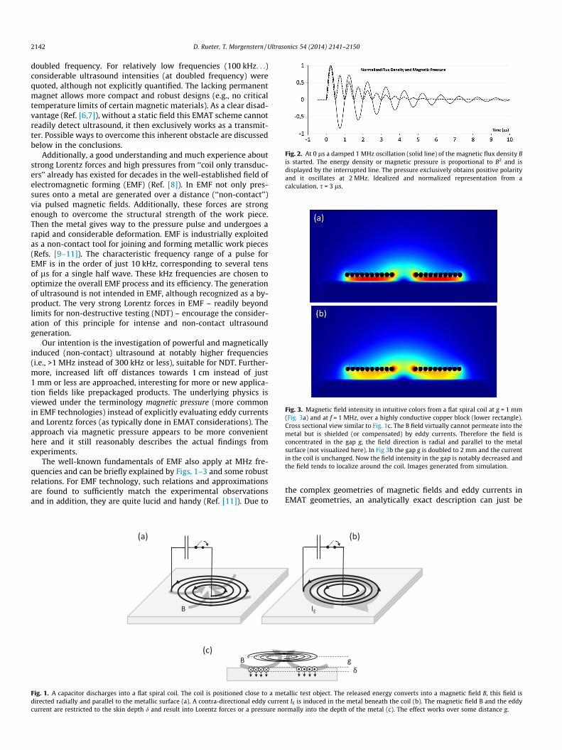
Fig. 2. At 0 ls a damped 1 MHz oscillation (solid line) of the magnetic flux density Bis started. The energy density or magnetic pressure is proportional to B2 and isdisplayed by the interrupted line. The pressure exclusively obtains positive polarityand it oscillates at 2 MHz. Idealized and normalized representation from acalculation, s = 3 ls.
Fig. 3. Magnetic field intensity in intuitive colors from a flat spiral coil at g = 1 mm(Fig. 3a) and at f = 1 MHz, over a highly conductive copper block (lower rectangle).Cross sectional view similar to Fig. 1c. The B field virtually cannot permeate into themetal but is shielded (or compensated) by eddy currents. Therefore the field isconcentrated in the gap g, the field direction is radial and parallel to the metalsurface (not visualized here). In Fig 3b the gap g is doubled to 2 mm and the currentin the coil is unchanged. Now the field intensity in the gap is notably decreased andthe field tends to localize around the coil. Images generated from simulation.
2142 D. Rueter, T. Morgenstern / Ultrasonics 54 (2014) 2141–2150
doubled frequency. For relatively low frequencies (100 kHz. . .)considerable ultrasound intensities (at doubled frequency) werequoted, although not explicitly quantified. The lacking permanentmagnet allows more compact and robust designs (e.g., no criticaltemperature limits of certain magnetic materials). As a clear disad-vantage (Ref. [6,7]), without a static field this EMAT scheme cannotreadily detect ultrasound, it then exclusively works as a transmit-ter. Possible ways to overcome this inherent obstacle are discussedbelow in the conclusions.
Additionally, a good understanding and much experience aboutstrong Lorentz forces and high pressures from ‘‘coil only transduc-ers’’ already has existed for decades in the well-established field ofelectromagnetic forming (EMF) (Ref. [8]). In EMF not only pres-sures onto a metal are generated over a distance (‘‘non-contact’’)via pulsed magnetic fields. Additionally, these forces are strongenough to overcome the structural strength of the work piece.Then the metal gives way to the pressure pulse and undergoes arapid and considerable deformation. EMF is industrially exploitedas a non-contact tool for joining and forming metallic work pieces(Refs. [9–11]). The characteristic frequency range of a pulse forEMF is in the order of just 10 kHz, corresponding to several tensof ls for a single half wave. These kHz frequencies are chosen tooptimize the overall EMF process and its efficiency. The generationof ultrasound is not intended in EMF, although recognized as a by-product. The very strong Lorentz forces in EMF – readily beyondlimits for non-destructive testing (NDT) – encourage the consider-ation of this principle for intense and non-contact ultrasoundgeneration.
Our intention is the investigation of powerful and magneticallyinduced (non-contact) ultrasound at notably higher frequencies(i.e., >1 MHz instead of 300 kHz or less), suitable for NDT. Further-more, increased lift off distances towards 1 cm instead of just1 mm or less are approached, interesting for more or new applica-tion fields like prepackaged products. The underlying physics isviewed under the terminology magnetic pressure (more commonin EMF technologies) instead of explicitly evaluating eddy currentsand Lorentz forces (as typically done in EMAT considerations). Theapproach via magnetic pressure appears to be more convenienthere and it still reasonably describes the actual findings fromexperiments.
The well-known fundamentals of EMF also apply at MHz fre-quencies and can be briefly explained by Figs. 1–3 and some robustrelations. For EMF technology, such relations and approximationsare found to sufficiently match the experimental observationsand in addition, they are quite lucid and handy (Ref. [11]). Due to
(a)
B
(c)B
Fig. 1. A capacitor discharges into a flat spiral coil. The coil is positioned close to a medirected radially and parallel to the metallic surface (a). A contra-directional eddy currecurrent are restricted to the skin depth d and result into Lorentz forces or a pressure no
the complex geometries of magnetic fields and eddy currents inEMAT geometries, an analytically exact description can just be
(b)
IE
δ g
tallic test object. The released energy converts into a magnetic field B, this field isnt IE is induced in the metal beneath the coil (b). The magnetic field B and the eddyrmally into the depth of the metal (c). The effect works over some distance g.
D. Rueter, T. Morgenstern / Ultrasonics 54 (2014) 2141–2150 2143
derived for simple geometries (such as a current line or a currentloop parallel over a metallic plane). Due to a more extensive andabstract evolution this way is not approached in this practicallymotivated contribution. Instead, the problem is modeled in aFEM computation (as also carried out in Ref. [5]). The FEM model-ing yields a numerical correction for some quite basal approxima-tions and finally, with this correction, the experimental values arefound in reasonable accordance:
A capacitor C is charged to high voltage levels U. The storedenergy E in the capacitor is (Eq. (1a))
E ¼ 12
C � U2 ð1aÞ
and
E ¼ 12
L � I2el ð1bÞ
In commercially available EMF machines E reaches or even con-siderably exceeds 10 kJ. After closing a switch (Fig. 1), the capacitorC will rapidly (in EMF: within 10�5–10�4 s) discharge into aninductor L. Such an inductor L can be realized as a flat spiral coil.For ideal elements (switch, L and C) the stored energy E is fully con-verted into a magnetic field of the inductor L with discharge cur-rent Iel, described by Eq. (1b). The arrangement represents asimple L-C-oscillation circuit; the current in the conductor (andthe associated magnetic field) then will oscillate with a character-istic frequency f. The characteristic electrical impedance Zel is theratio of voltage amplitude and current amplitude in the oscillatingL-C-circuit:
f ¼ 12p
ffiffiffiffiffiffiffiffiffiL � Cp ð2aÞ
Zel ¼ffiffiffiLC
rð2bÞ
For NDT ultrasound, L-C-frequencies in the order of 106 Hz areinteresting and this can be readily achieved by choosing elementsL and C with relatively smaller values. The available maximumelectrical power Pel,max from such oscillating L-C-circuit is
Pel;max ¼14� U
2
Zel¼ 1
4� 1ffiffiffiffiffiffiffiffiffi
L � Cp � C � U2 ¼ p � f � E ð3Þ
When extracting this available maximum power (Eq. (3)) fromthe L-C-circuit, the oscillating energy (Eq. 1) will essentially beconsumed in less than a single half-wave. Pel,max is used below asa reference power for efficiency considerations.
In practical setups, neither the coil nor the switch nor thecapacitor is ideal. The energy losses and resistance of these ele-ments result into a damped oscillation of the current or the mag-netic flux density B
BðtÞ � sinð2pftÞ � e�ts ð4Þ
where s = L/R and R is an equivalent serial resistance in the L-C-cir-cuit to represent energy losses after closing the switch. Fig. 2 dis-plays a damped 1 MHz oscillation with s = 3 ls.
When positioning a flat spiral coil L close to a metallic objectin a distance g (the lift off gap), the magnetic field B has a mainlyradial component parallel to the metal surface. The oscillatingfield will induce an annular and contra-directional eddy currentin the metal below the spiral (Fig. 1a and b). This eddy currentcouples back to the spiral coil and affects the frequency f (usuallyincreases) and the decay time s (usually decreases) of the L-C-cir-cuit. Particularly at very close coupling between inductor andmetal noticeable changes result. The general L-C-behavior how-ever, is not principally affected at moderate coupling, and for
the sake of clarity these effects are not explored in more detailhere, see instead a focused elaboration in Ref. [6].
It is well known that an RF eddy current is carried by just athin surface layer of the metal, with effective thickness d (‘‘skin’’,skin effect) (see e.g. Ref. [12]). At 1 MHz, the characteristic thick-ness d is about 85 lm for aluminum, about 400 lm for (non-fer-romagnetic) stainless steel and for ferromagnetic steel about10 lm (if magnetic flux density below saturation, up to 1.5 T)or about 200 lm (flux density above 2 T) (Ref. [12]). Neitherthe eddy current nor the RF magnetic field can permeate themetal much deeper than the skin depth d: the induced and con-tra-directional eddy current itself generates a magnetic field. Thatadditional field finally eliminates (subtracts) all resulting mag-netic field below the skin depth. It increases (adds, directionreversed) the resulting magnetic field above the surface, withinthe lift off gap. Furthermore, above the excitation coil (here theexcitation field is reversed) the eddy current again weakens thefield. Therefore, the resulting magnetic field B at RF frequenciesand in an arrangement according to Fig. 1 is practically forcedabove and parallel to a metal surface, and in addition, the highestflux densities are present in the lift off gap g.
It should be noted that for a given RF magnetic field the totaleddy current is – even for different metal types with differentconductivity – virtually the same. This behavior implicitly resultsfrom the compensation – by eddy currents – of all inductionfields in the volume of a metal. Fig. 3 illustrates a FEM simulationfor a magnetic flux density. The computed scenario displays thecross section of a ‘‘flat spiral coil with RF excitation above ametallic surface’’. The intensity of B is intuitively representedby the color. Near the metal, the B field is directed parallel tothe surface, the direction itself is not visible in this presentation.The B field does virtually not permeate the metal; it is restrictedto the relatively thin surface layer d. In the gap g between metaland coil the field appears relatively strong and (particularly forFig. 3a) fairly homogeneous. Above the coil the field is muchweaker; the field is not symmetric with respect to the coil plane.For different kinds of metal (different skin depth d) the generalappearance of Fig. 3 does virtually not change, as long as thegap g between coil and metal is significantly higher than skindepth d (which is implied in this simulation).
As a further remark, the virtually equal eddy currents for quitedifferent types of metals (good conductivity vs. poor conductivity)do not imply an equal energy consumption from the excitationcoil: The phase between voltage and current of the inductor systemis shifted below 90� by imperfect conductors (either caused by theimperfect coil itself or by the inductively coupled target metal),thus increasing the effective serial resistance R and reducing thes (Eq. (4)). Actually, a reduced s for a target metal with relativelypoor conductivity – here stainless steel – is experimentallyobserved below.
When comparing the modeling of Fig. 3a and b (same excitationcurrent implied), the field in the smaller gap of Fig. 3a appears tobe more concentrated and more homogeneous. In addition, theresidual field above the coil plane is weaker than in Fig. 3b. Thefield intensity around the coil is considerably deformed by thesuperimposing field from the eddy current. When numericallyintegrating the magnetic energy density (being proportional toB2, see from Eq. (5) below) over the volume in the FEM models,for Fig. 3a about 69% of the total magnetic field energy is accumu-lated in the volume below the coil center plane. Actually it is con-centrated between the coil windings and the metal surface. For thescenario with the increased gap (Fig. 3b) the relative energy con-tent in the gap accounts to a somewhat less 65%, relatively morefield energy is then also present above the coil, apart from thetarget.
2144 D. Rueter, T. Morgenstern / Ultrasonics 54 (2014) 2141–2150
As a reasonable approximation – derived from such FEM data(Fig. 3a and b) and as usually done in EMF techniques – it can bestated, that in a scenario where the gap g is smaller than 1/10 ofthe active radius of a flat spiral coil, the magnetic energy of the sys-tem (Eq. (1b)) will predominantly (i.e., >70%) be present in the gap.
The annular eddy current and the mostly radial magnetic field –both parallel to the metal surface – result into Lorentz forces. Thesedistributed forces are directed normally into the depth (Fig. 1c) andare experienced as a pressure p. As an important detail, this pres-sure is also positive for a negative half wave of the oscillating mag-netic field (Fig. 2 and Refs. [5,7]). Not only the B field but also theaccompanying eddy current periodically changes the polarity, onlypositive pressure is produced (as intended in EMF). As an inherentconsequence the Lorentz forces or pressure then will then oscillateat a doubled frequency (Ref. [7]). Furthermore, the Lorentz force isproportional to the magnetic flux density B and the eddy current,which itself is proportional to B. Then the Lorentz force and theexperienced pressure is proportional to B2 (Ref. [7]).
It is well known in EMF and other disciplines like magneto-hydrodynamics (Ref. [13]) that this experienced pressure p actuallyequals the energy density of an oscillating or transient magneticfield parallel and in contact to a metallic surface:
p ¼ 12� B
2
l0ð5Þ
l0 represents the magnetic permeability of the vacuum. The energydensity of a magnetic field is, therefore, also denoted as the mag-netic pressure p. It readily manifests as an ordinary mechanical pres-sure (Ref. [13]), when exposing sufficiently conductive matter (i.e.,the skin depth d is small with respect to other geometries, compareFig. 3) to a transient magnetic field. Interesting for acoustics, withjust the known magnetic pressure p or the known magnetic fluxdensity B in vicinity to a good conductor (metal with relativelysmall skin depth), a more detailed and complex determination ofeddy currents and finally resulting Lorentz forces is not necessarilyrequired. And, since most of the pressure is directed normally intothe depth of the metal, a preferred excitation of longitudinal waves,propagating normally into the depth, can be expected. This isalready described by previous workers, here cited from Ref. [5]:‘‘the out-of-plane Lorentz force (into the depth) due to the dynamicfield is about 10 times larger than the (lateral or radial) in-planeforce.’’ Only relatively small B field components are directed nor-mally into the depth of the metal, basically located at the innerand the outer radius of the spiral coil. Here the field penetratesand then leaves the thin skin layer, and together with the annulareddy current some – relatively small – Lorentz forces in radial direc-tion are generated.
At B = 1 Tesla the magnetic pressure is close to 400 kPa or 4atmospheres (Eq. (5)) and this equals an energy density of 0.4 Jper cm3. In industrial EMF, an energy amount of about 15 kJ is con-verted into magnetic field energy. The magnetic energy, being pro-portional to B2, is mainly (>70%) located and concentrated in thegap between coil and metal surface. Given that 10 kJ is homoge-neously distributed in a volume of 100 cm2 (here just taken as anexample for the effective free space between coil and work piecein EMF applications), the mechanical pressure on the metal thenwould be 1000 atmospheres. This can rapidly deform a metallicwork piece. That pressure is equivalent (Eq. (5)) to a magnetic fluxdensity B = 16 T. In fact, even higher pressures are reported in EMFtechniques.
It should be noted that the limiting problems in the EMF tech-nique arise from the vast Lorentz forces acting on the coil windingsrather than just heat due to the very strong current pulses. Further-more, all known ferromagnetic materials are saturated above B = 2T; thereby an iron or ferrite core will not significantly improve
these techniques. The work is usually done with compact and rigid‘‘copper alone’’ coils. As an interesting side remark, ferromagneticiron will not be attracted by a strong magnetic induction fieldbut it will be repelled, as all other non-magnetic metals.
The effective sound intensity I of an ultrasound wave at soundpressure p (peak value) in a material is
I ¼ p2
2 � ZMð6Þ
with the characteristic acoustic impedance ZM. At first sight,when implying a direct conversion of oscillating magnetic pres-sure into sound pressure, the excited sound intensity I shouldincrease with B4 or the stored energy E2 (just by combiningEqs. (5) and (6)). This is a quadratic effect or an effect of secondorder. The relation directs the way towards non-contact and highintensity ultrasound generation via a ‘‘coil only transmitter’’: theultrasound power should increase with the square of excitationpower.
As an example, the magnetic pressure and the acoustic pressureat B = 1 T are given as 400 kPa (0.4 J/cm3) and 200 kPa respectively.Only 200 kPa can be utilized for the acoustic pressure, because thefull wave (peak to peak, from –200 to +200 kPa) must be within themagnetic amplitude of 400 kPa (see Fig. 2). The sound intensity I ofa longitudinal bulk wave in aluminum (ZM � 17 � 106 Ns/m3) thenwould be 1175 W/m2 (Eq. (6)) or roughly 0.12 W/cm2. At a givenvolume of 0.1 cm3 for the magnetic energy (from spiral coil at1 mm lift off gap g and 1 cm2 footprint area A) and a frequencyof 1 MHz the available power Pel,max in the LC – circuit should beat least 40 mJ � p � 1 MHz = 125 kW (from Eq. (3)). This accountsfor the ideal case that all magnetic energy is exclusively and homo-geneously allocated within the gap. Actually, only about 70% of theenergy is in the gap (see the FEM discussion above) and secondly,the field is not exactly homogeneous in the gap but graduallyweakened towards the metal target. This local inhomogeneity will,evaluating the FEM data in the gap and the B2 dependence of thepressure, result in an additional 70% drop. Together these realeffects account to a pressure reduction of approximately 50%. Thenfor 0.12 W ultrasound at 2 MHz in aluminum an available power ofabout 250 kW at 1 MHz should be present in the LC-circuit. Now aflux density of 1 T can be expected onto the metal. This suggestspoor conversion efficiency and a vast mismatch situation; thevibrating metal surface can only convert about 0.5 ppm from theavailable power.
When applying a 100-fold higher electrical power density in thegap, i.e., an available power of 25 Megawatts at 1 MHz, the energyand the magnetic or acoustic pressure also increases 100-fold. As aresult (Eq. (6)) a much more powerful ultrasound signal – nowabout 1.2 kW – is expected, corresponding to a magnetic flux of10 T near the metal and a peak pressure of 40 MPa. Furthermore,the efficiency is improved significantly to 50 ppm, but is still notvery good. To the benefit of this number, that available maximumpower as a reference level is not identical to the actual power dis-sipation (which is considerably smaller) of the total system, andthe local power dissipation in the metal is even much smaller.
It should be noted that this particular example (25 MW avail-able power at 1 MHz, g = 1 mm and A = 1 cm2, resulting into40 MPa peak pressure) is – within reasonable accuracy – practi-cally verified in the experiments below.
In a general formulation of the above considerations, the finallytransmitted ultrasound power PUS of a ringing LC-circuit withreleased energy E, lift off g and coil area A over a metal with acous-tic impedance ZM can be stated as
PUS ¼E
g � A �12� 12
� �2
� 12 � ZM
� �� A ð7Þ
D. Rueter, T. Morgenstern / Ultrasonics 54 (2014) 2141–2150 2145
This formula should be fairly accurate for a situation, where g isabout 1/10 of the coil’s diameter (or the square root of the footprintarea A), see FEM results in Fig. 3 and considerations above. And, onthe other hand, the skin depth d should be notably smaller than g.Inside the left bracket is the magnetic pressure, equivalent to themagnetic energy density: total energy E over active volume andthen reduced to 50% by real effects, derived from FEM analysis.Another 50% reduction of the magnetic pressure is caused by thejust 50% utilization of the only positive amplitude (Fig. 2) for bipo-lar acoustic amplitudes. Then the resulting acoustic pressure in theleft bracket is squared and divided by 2 ZM (the second bracket)and this is just the sound intensity according to Eq. (6). Actually,with a released energy of 8 J at f = 1 MHz, equal to an availablepower of 25 MW (Eq. (3)), and the geometries of g = 1 � 10�3 mand A = 1 � 10�4 m2, in aluminum a momentary ultrasound powerof 1175 W (equal to a momentary peak pressure of 40 MPa over1 cm2) is obtained from Eq. (7) and this was already discussed inthe example above.
An efficiency g as the ratio PUS=Pel;max can be readily derivedfrom Eqs. (7) and (3):
g ¼ PUS
Pel;max¼ 1
32� EZM � A � g2 � p � f ð8Þ
Eq. (8) can be altered by replacing the corrected energy density E/(2 � A � g) by an energy density B2/2l0:
g ¼ 132� B2
ZM � l0 � g � p � fð8bÞ
Eq. (8b) describes the efficiency as a function of the flux density B invicinity to the metal. There are similarities to an expressionreported much earlier by Dobbs (Ref. [14,15]):
g ¼ PUS
PRF¼ B2
0
ZM � l0 � d � p � fð9Þ
Despite the obvious similarity, the equation from Dobbs wasderived in a quite different way, it has a somewhat different mean-ing and it applies for conventional EMATs with static field B0.
When directly comparing Eqs. (8b) and (9), there appears a fac-tor of 32 to the benefit of conventional EMATs. Another substantialdifference to Eq. (8b) is that the skin depth d appears instead of thelift off gap g. Since d� g in relevant applications and together withthe factor of 32, the efficiency of a conventional EMAT (Eq. (9))seems to be very much higher than in the coil only concept fromabove (Eq. (8b)). This is however not the case, as briefly discussednow.
It must be noticed that in Eq. (9) just the absorbed power PRF
(Refs. [14,15]) is taken as the reference level for the ultrasoundpower PUS. Eq. (9), therefore, only addresses the local conversionefficiency within the test metal, with a somehow given field B0
and a somehow inductively inserted net power PRF. In contrast,Eqs. (8b), (8) offers a global description for the total setup, includ-ing the distant ‘‘coil only EMAT’’ and real attenuation effects over adistance g. And additionally, a much higher available maximumpower in the LC-oscillation circuit is taken as the reference levelfor the conversion efficiency. The available maximum power inan oscillating LC-circuit even is considerably higher than the actualpower dissipation (depending on s, Eq. (4)) in the total system.
Particularly and to the benefit of coil only EMATs, the RF B-fieldcannot permeate into the depth of the metal; the field energy isconcentrated close to and above the surface (Fig. 3), and this effectnotably increases the energy density – equivalent to pressure. Tothe contrary, a static field B0 from conventional EMAT will expandinto the metal and this considerably dilutes the energy density B0
2.For partial compensation the field source B0 usually must be over-sized, both in geometry (resulting in less compact designs) and
total magnetic field energy. Therefore, the skin effect for an RF B-field should not be seen as a disadvantage but as an advantage.The skin effect helps to concentrate the B field in the region ofinterest. In particular, very high flux densities above 2 T (hardlypossible for conventional EMATs) can be realized in the relativelysmaller volume, see EMF and see the observation in Ref. [5] withthe superior dynamic field. Additionally, the regions of high induc-tion field automatically coincidence with the regions of high eddycurrents. This is not necessarily the case for conventional EMATswith separated field generation.
In another substantial difference to normal EMATs the coil onlyconcept will – since only positive pressures result (Fig. 2) – transfera linear momentum (‘‘LM’’) to the metallic test object. The testobject will be repelled by the inductor and this is the intentionalpurpose in EMF technologies. A linear momentum can be easilydetermined by measuring the (constant) velocity of a mass, aftermomentum transfer by the coil. The linear momentum LM is deliv-ered within a few periods of the MHz oscillation, Fig. 2 suggests thecompletion of the process after a few ls.
Since in Fig. 2 the maximum pressure p (and also the maximumforce F) is normalized to ‘‘1 N/m2’’ or ‘‘1 N’’ for the damped oscilla-tion with f = 1 MHz and s = 3 ls, the normalized linear momentum(‘‘NLM’’) from this magnetic pressure oscillation is
NLM¼Z 1
0FðtÞdt¼
Z 1
01N �sin2ð2pftÞ �e
�2ðt� 14fÞ
s dt�0:88 �10�6 kgms
ð10Þ
For an experimental high power oscillation with frequency fand decay time s – which both are easily observable with a stan-dard oscilloscope – the real linear momentum LM of the repelledtest object can be set in relation to the normalized momentumNLM. The ratio of real LM to NLM equals the ratio of real maximumforce Fmax to 1 N. For 1 MHz and s = 3 ls:
Fmax
1N¼ LM
0:88 � 10�6 kg ms
ð11aÞ
In more general, for any other frequencies f and other decaytimes s of a pulsed LC-discharge:
Fmax ¼LM
R10 sin2ð2pftÞ � e
�2ðt� 14fÞ
s dtð11bÞ
Quantitative information about Fmax is very welcome, sincehereby also the practical and maximum magnetic pressure pmax
is reasonably accessible via the affected area A. Obviously, pmax istied to the achieved sound pressure in the metal.
pmax can be compared with the total energy E in the system(stored in the capacitor C before switching), in best case it shouldequal the energy density in the gap g with area A. In practical set-ups and as discussed above, with a distance g � 1/10 �square root(A), the energy density close to the metal is expected to be only50% of the best case limit E/g � A.
2. Techniques, equipment and experimental setup
50 high voltage (40 kV max) and 3 nF ceramic pulse capacitors(Murata DHS N4700) were combined in parallel to 150 nF. Suchceramic capacitors are commonly used e.g. in pulsed excimerlasers (Ref. [16]), where the stored energy must be deliveredwithin some tens of nanoseconds and, consequently, at power lev-els of many Megawatts and currents in the kA range. These pulsecapacitors obtain low internal inductance and resistance and theyare proven to deliver many millions of pulses over their lifetimewithout fatigue or failure.
The multiple capacitors were interconnected with a low induc-tance wiring (short and wide strips). At an experimental charge
2146 D. Rueter, T. Morgenstern / Ultrasonics 54 (2014) 2141–2150
voltage of 15 kV the stored energy E is close to 17 J (Eq. (1)). A stan-dard high voltage DC supply with an adjustable current up to20 mA and adjustable voltage up to 30 kV was used as a chargesupply for the 150 nF. It is connected over a high voltage resistor(500 O) for decoupling the pulsed power from the DC supply.
For a desired oscillation frequency of 1 MHz, a total inductanceLT = 170 nH (including the parasitic inductance LP from all wiring,switch, capacitor) is required (Eq. (2)). The spiral coil LI, therefore,must be less than 170 nH. Since the stored energy E in capacitorbank C is converted to a major portion into magnetic field energyE = L/2 � I2 (Eq. (1b)) the maximum discharge current after closingthe switch should then be close to 14 kA. The characteristic electri-cal impedance Zel of such L-C-oscillation circuit is then 15 kV/14 kA � 1 O (or alternatively by Eq. (2)). All real resistance in theLC-circuit must be held significantly below 1 O for an oscillationwithout excessive attenuation: Eq. (4), s = L/R > 3 ls, better:s > 4 ls. The available maximum power (Eq. (3)) is then close to52 MW at stored energy E = 17 J.
Not all power or magnetic energy is present in the spiral coil LI,because the energy is proportionally divided to the all serial induc-tances LT = LI + LP in the system. Without spiral coil LI (shortcut)and from parasitic LP only, the observed oscillation (or resonance)frequency of the system is 1.43 MHz, and (Eq. (2)) LP � 83 nH. Inconsequence, LI must be 85–90 nH to meet the 1 MHz and onlyabout 50% of the total energy or available power is present in theflat spiral coil, about 8 J. Then it can be reasonably estimated thatonly about 25 MW or less can be provided from the spiral coil.Without load (not coupled to metal target), a s � 4 ls is observa-ble. Therefore all resistances in the system (switch closed) addup to less than 0.1 O.
The high power oscillation event can be readily observed from adistance of about 20 cm with a single loop of copper wire. Thediameter is about 5 cm and the loop is loaded with a very lowinductance 0.2 O resistor (i.e., a bundle of many resistors in paral-lel). The voltage over the 0.2 O is proportional to the current in theloop and can be readily observed via standard coax cable with astandard oscilloscope. Actually, the current in the loop is predom-inantly an eddy current from the distant LC-pulse generator, and itresembles the discharge current in the LC-circuit itself. With theobserved oscillation and attenuation, a reasonable estimation of fand s is possible. Due to the high momentary power no extraamplifier is needed, the signal from the loop (several Volts) is wellsuited for a standard oscilloscope. It must be noted that definitelyan inductive signal is detected and not any other EMI effect: themagnetic coupling of the loop can be readily verified by just twist-ing the loop by 90� (plane then parallel to B). The signal thenvanishes.
An important element for the pulsed LC-circuit (Fig. 1) is theswitch. Required properties are low inductance (�150 nH), lowresistivity (�1 O) and the capability to bear 15 kA and to with-stand 15 kV. Furthermore, the switch must tolerate positive andnegative currents during the oscillation and it must transit fromhigh impedance (�1 M O) to low impedance (�1 O) within a timemuch smaller than 1 ls.
The requirements can be matched with commercially availablethyratron tubes. Nowadays even an all-solid-state switching isestablished for similar applications, partly combined with mag-netic pulse compression (compression in time). These all-solid-state techniques are maintenance free and have demonstrated apractically unlimited lifetime (Ref. [16]).
In our experiments, for the sake of simplicity and flexibility, alow inductance spark gap with sound absorber was applied, simplyworking in air. The switching time of such spark gap after ignitionis much shorter than 1 ls (can be few nanoseconds) (Ref. [17]) andall requirements above (15 kV, 15 kA,�1 O after ignition) are wellfulfilled. A certain amount of energy is consumed for the formation
of very conductive and highly ionized plasma in the spark gap; thisenergy (estimated <5 J) is taken from the initial energy in thecapacitor. For high power and ‘‘coil only’’ ultrasound generation asimilar circuitry with a triggered spark gap was already presentedin Ref. [7], although discussed only for smaller ultrasound frequen-cies (100 kHz. . .) and – together with a copper foil very close to thecoil – intended as a mechanically contacting transducer for appli-cations on (non-metallic) concrete. The basic disadvantage of suchold-fashioned high power switch is the burn-off behavior after sev-eral hundred shots, requiring frequent maintenance. A silencer ismandatory: the plasma flashes emit considerable noise, naturallyincluding ultrasound.
Therefore it is also interesting to compare the ultrasound pulsesfrom a ‘‘coil only EMAT’’ with the impact of 17 J sparks itself fromthe capacitor bank. The sparks can be directly released onto thesurface of the metallic test sample. Although representing a non-contact method over a certain distance (about 9 mm gap from elec-trode to surface), such spark technique cannot be called non-destructive. Considerable scorch marks affect the surface, and thiscannot be tolerated in every application.
Additionally, a comparison with laser induced ultrasound is car-ried out (Refs. [18–20]), from a pulsed Nd:YAG laser (Quantel Ultra100) emitting at 1064 nm and 532 nm.
The laser pulse delivers 20 mJ energy within 8 ns and it isfocused onto a small spot (<1 mm2) of the test metal. As with thespark, the method is non-contact but however not ‘‘non-destruc-tive’’: breakdown plasmas and impact marks affect the surface.These micro-explosions on the surface are apparently requiredfor noteworthy ultrasound signals.
The flat spiral coils itself were made from standard PCB materialwith an extra thick copper layer (120 lm) or are, alternatively,manually wound spirals from regular copper wire. These spiralcoils with a diameter of 25 mm down to 10 mm consist of just afew windings (<10) to meet the <170 nH requirement forf = 1 MHz. Due to the skin effect at 1 MHz in copper, the conductingmaterial is not needed to be much thicker than 0.2 mm. In thepulsed power application the coils are exposed to high mechanical,thermal and electrical stress. The spiral coils were immersed inepoxy resin to mechanically stabilize and to electrically insulatethe windings, since already two neighbored windings (=1 turn)must withstand a RF voltage difference of about 1000 V. Practicallyeven more delicate is the voltage difference towards the test metal.Since an air gap (=the lift of distance g) of even almost 1 cm is over-come by the 15 kV, the surface area of the spiral coil is insulated bya 200 lm polymer foil (similar to Polyimide), laminated onto thecoil with epoxy resin. With these insulating layers onto the surface,a gap g to a test metal of at least 0.5 mm is defined. An imperfec-tion in the insulation – this already can be a small air inclusion –regularly results in instantaneous failure of the coil within onepower pulse. On the other hand, a well handcrafted coil withstandsa virtually unlimited number of shots.
Interestingly, the mechanical and thermal stability of the coilsappears to be less delicate. The ls short and intensive mechanicalforces can apparently be taken by the inertial mass of the high den-sity copper material. Thermal problems become an issue at highrepetition frequencies. At low repetition rates of about 1 Hz, a con-ventional air blower is sufficient for cooling a free standing coil. Forhigher repetition frequencies (10 Hz. . .) the back of the spiral coilwas laminated onto a ceramic boron nitride block. This materialis both a good electrical insulator and a good thermal conductor,thereby acting as a heat sink for the relatively small coil.
An aluminum rod with 30 mm diameter and 0.89 m lengthserved as metallic test material, Fig. 4. The two end faces are plane.One face is exposed to a non-contact ultrasound generator, i. e., acoil only EMAT or the 17 J spark impact or the laser pulse. Theother face was equipped with a ceramic PZT disk (10 mm diameter,
89 cm
g: 1 ….20 mm
Fig. 4. Experimental setup. The spiral coil transmitter is positioned in a distance gto an aluminum rod. The other end of the rod is equipped with a piezo crystal anddetects ultrasound events with a 140 ls delay from the 89 cm rod.
D. Rueter, T. Morgenstern / Ultrasonics 54 (2014) 2141–2150 2147
1 mm thickness), this piezo crystal was attached onto the alumi-num face with paraffin wax. The two contacts of the piezo wereloaded with 100 O and a parallel inductor of 3 lH for a preferedselection of 2 MHz and at 700 kHz bandwidth. This detector wasdirectly connected to a standard oscilloscope; no extra signalamplifier was involved here.
An ultrasound shot into the rod́s ending should result in a piezosignal at the other side after the characteristic runtime along 89 cmin aluminum: 0.89 m/6350 ms�1 � 140 ls. The delay time of140 ls is well suited to distinguish strong electromagnetic inter-ference (EMI) from a real ultrasound signal in the aluminum. Thealuminum rod works as a waveguide and it actually dispersesthe ultrasound into several modes of longitudinal propagation.The investigation of this mode dispersion is however not withinthe scope of this contribution, see instead Ref. [21].
Furthermore, 30 � 30 mm platelets from aluminum, ferromag-netic steel with and without zinc coating and stainless steel(non-ferromagnetic) were prepared. These metal chips wereplaced, in a horizontal setup, onto the spiral coils. Within a mag-netic pulse, a metal chip receives a linear momentum LM (Eqs.(10) and 15) and jumps against earth’s gravity to a certain heighth. This height h is readily observable with sufficient accuracy (onlyapplies in square root of Eq. (16)), even with the naked eye. It mustbe noted, that an insulating material (e.g., a glass plate) does notjump. The LM is actually provided by the electromagnetic pressureand not by any mechanical vibration. The LM of the metal chip is
LM ¼ m �ffiffiffiffiffiffiffiffiffiffiffiffiffiffiffiffi2 � G � hp
ð12Þ
with m = mass of the metal chip, gravity G = 9.81 m/s2, h = achievedheight. With the known LM the maximum force Fmax (Eq. (11b)) isderived, and then together with the inductive footprint area A, acharacteristic magnetic pressure is accessible.
3. Experimental results
In Fig. 5 the oscilloscope screenshots from an 8 J pulse (i. e., atotal 17 J energy in the system, including the parasitic inductances)through a spiral coil with approximately 1 cm2 footprint A and1 mm gap g to the aluminum rod are displayed. Channel 1 displaysthe piezo signal and channel 2 (also used for triggering) representsthe induction signal in the wire loop.
In Fig. 5a clear piezo signal after 140 ls and with 15 V ampli-tude is present. In this moment, the piezo delivers more than2 W of electrical power into the 100 O load. Note that the piezocovers only 10% of the rods face and it is not well coupled (just aparaffin wax layer with unintentional air inclusions) to the alumi-num. Unquestionably the piezo detects a considerable ultrasoundsignal at the expected delay time. Even a multiple echo (distancethen 280 ls, several times travelling forth and back over 180 cm)is observable, but not shown here. The discrete replicas in the
ultrasound signal after 140 ls and at a characteristic distance ofabout 10 ls originate from different propagation modes (Ref.[21]) in the 30 mm rod, which also shall not be further discussedhere.
Fig. 5b zooms into the electromagnetic excitation at t = 0 ls. Adamped oscillation at 1 MHz is present in channel 1, the decaytime s resembles Fig. 2, and the amplitude halves every 2 ls.Therefore, s can be reasonably estimated to be 3 ls here.
Fig. 5c zooms into the piezo signal after 140 ls. The predomi-nant frequency is close to 2 MHz. The effective duration of areceived ultrasound pulse signal (within a certain propagationmode) is 2–3 ls. The actual duration is assumed to be even shorter,since the piezo detector itself exhibits some time constant or lim-ited bandwidth.
When comparing the above ultrasound intensity (using theexact same piezo detector) with those signals from a direct 17 Jspark impact into the aluminum rod or a nanoseconds laserimpact, the electromagnetic method outperforms the other meth-ods by far: the spark signal shows a very similar pattern in timeafter 140 ls (Fig. 5a) but achieves only 0.5 V amplitude and thelaser pulse induced ultrasound (including plasma and resultingpoint defect on the aluminum surface) is just close to 0.03 V.
The electromagnetic induced ultrasound intensity I at 2 MHzand in W/cm2 is, therefore, almost 1000 times stronger than fromthe direct spark impact with even doubled energy (17 J) and250,000 times stronger than from the laser shot.
To better quantify the ultrasound intensities and pressures,1 MHz electromagnetic ‘‘jump’’ experiments were made, hereagain with about 8 J energy in the transducer coil. Table 1 repre-sents the data:
Experimental uncertainties exist with the experimentalmomentum LM (particularly the smallest jump from the stainlesssteel is not very accurate), with the characteristic decay time ofthe oscillation s and with the actually affected area A. Neverthe-less, a virtual independence of the experienced pressures fromthe metal type is obtained. The magnetic pressure implies a mag-netic field of B � 10.5 T and a magnetic energy density of �4 J/0.1 cm3 close to the metal. Actually, a total magnetic energy ofabout 8 J or an available power of 25 MW was present in the coil.The experimentally observed reduction of magnetic energy den-sity down to only 50% close to the metal is in well accordanceto the above considerations from the FEM model and the hereincomputed distribution of field energy. Furthermore, the jumpdata is – within the limited experimental accuracy of such deli-cate high voltage experiments – in quite reasonable accordanceto the discussed example above, with the presumed 10 T andthe equivalent 40 MPa.
Fig. 6 reveals the ultrasound amplitude at 2 MHz as a functionof capacitor charge voltage (Eq. (1)) and at fixed geometry. Thecharge voltage (‘‘kV’’) proportionally converts into flux density ofthe spiral coil (‘‘V s/m2’’) and the ultrasound power – as discussedin the introduction – should increase with B4 and the sound pres-sure p with B2. The piezo signal is proportional to the sound pres-sure or amplitude, and therefore, the piezo signal should increasewith the square of the capacitor charge voltage. A parabola isexpected and apparently, this is quite well matched. Also at16 kV charge, a piezo signal of almost exactly 16 V is obtained (thisvalue not included in the graph for better representation of thesmaller values).
Fig. 7 shows the electromagnetically induced 2 MHz ultrasoundafter 140 ls as a function of ‘‘lift off distance’’ g for two differentspiral coils. One coil has an effective diameter of 3 cm, the other1.4 cm. The area A of the circles is respectively 7 cm2 and1.5 cm2. These areas just can be counted for approximately 2/3,due to the inner bore in the spiral coil. The corrected A for the coilsis then about 5 cm2 and 1 cm2.
Fig. 5. Ultrasound signals (upper line) and induction signals (lower line) from a multi MW induction pulse at 1 MHz. Signal amplifiers are not required. At 0 ls the inductionpulse and after 140 ls a strong ultrasound signal appears, separated in discrete propagation modes through the aluminum rod. In (b) the induction pulse. Besides an EMIaffected first half wave, a regularly damped 1 MHz oscillation with s � 3 ls appears. The ultrasound signal in (c) obtains strong 2 MHz components.
Table 1Electromagnetic jump experiments against earth’s gravity. Different metal chips are vertically repelled to a certain height h by a spiral coil with A � 1 cm2 and g � 1 mm. The coilis excited with 2–3 ls short pulses at 1 MHz and 8 J energy, equivalent to 25 MW available power. Momentary pressures of about 40 MPa act on the metal chips, equivalent to aflux density of about 10 T.
Material and Size of the metal chip Aluminum30 � 30 � 1 mm3
Ferromagnetic steel30 � 30 � 0.55 mm3
Stainless steel non-ferromagnetic30 � 30 � 1 mm3
Mass of the chip 2.43 � 10�3 kg 3.91 � 10�3 kg 7.08 � 10�3 kgJump height h 0.13 m 0.03 m 0.008 mExperimentally observed Linear Momentum LM
Normalized linear momentum (NLM) (Eq. (10)) s � 3 ls s � 2 ls s � 2 ls8.8 � 10�7 Ns 6.4 � 10�7 Ns 6.4 � 10�7 Ns
Maximum force Fmax (Eq. (11b)) 4430 N 4700 N 4370 NMaximum magnetic pressure pmax (A � 1 cm2) 44 � 106 Pa 47 � 106 Pa 44 � 106 Pa
�440 Atmospheres �470 Atmospheres �440 AtmospheresMaximum acoustic pressure at 2 MHz 22 � 106 Pa 23 � 106 Pa 22 � 106 PaMomentary acoustic intensity at 2 MHz (Eq. (6)) 1.4 kW/cm2 0.6 kW/cm2 0.55 kW/cm2
Fig. 6. Piezo amplitude at 2 MHz as a function of capacitor charge voltage. Theobserved data direct to a second order (quadratic) relation. Here for comparison asimple parabola y = x2/16, dashed line. Actually, also at 16 kV charge a signal closeto 16 V results. This is not shown here for better representation of the smallervalues.
Fig. 7. Piezo amplitude at 2 MHz for a 1 cm2 (white squares) and a 5 cm2 coil (blacksquares) at constant energy and as a function of distance g. Towards increasing g thesmaller coil is more affected. On the other hand, at small distances the smaller coilis more effective. For comparison, the functionality of Eq. (8) is displayed(Ultrasound Intensity � 1/g2, white triangles). At relatively low distances g the realbehavior can be fairly matched.
2148 D. Rueter, T. Morgenstern / Ultrasonics 54 (2014) 2141–2150
D. Rueter, T. Morgenstern / Ultrasonics 54 (2014) 2141–2150 2149
At the same total energies, the ultrasound intensity and conver-sion efficiency is significantly higher for the smaller coil atg = 1 mm, following Eqs. (7) and (8) with the suggestion of thepower density as a relevant parameter for efficient electroacousticcoupling.
With increasing gap g the ultrasound intensity rapidlydecreases, almost exponentially. The smaller coil is affected moreby the distance, so that above g = 1 cm the wider coil becomessuperior. Actually the magnetic field energy is more localizedaround a smaller coil, all gradients are higher. In consequence,the magnetic pressure �B2 of a small coil is more affected by dis-tance than for a wider coil.
It must be noted that for higher distances g the B field becomesquite inhomogeneous in the gap, it gradually localizes towards thecoil (Fig. 3b). Additionally the affected footprint area A willincrease. Therefore a simple calculation of the behavior with Eq.(7) will not match for higher distances; the actual situation thenbecomes more disadvantageous. However at small distances (1–3 mm) and for the 5 cm2 coil, the simplified relation from Eq. (7)seems to fairly match the experimental observations.
4. Discussion and conclusion
The experimental findings, although not obtained in utmostaccuracy due to the quite delicate handling with an open high volt-age capacitor with considerable pulsed power capability, appar-ently support the key considerations of this contribution.
The jump experiment comes close to the example from theintroduction, where from a 25 MW available power at 1 MHz asound intensity I or power (A = 1 cm2) of 1.25 kW at 2 MHz waspredicted for aluminum, equivalent to 40 MPa peak pressure. Inthe experiments, the power offering was about 25 MW at 1 MHzand resulted to nominally 44 MPa peak pressure. The differenceis – as we believe – reasonably small within the accuracy of allexperimental uncertainties and approximations.
A noteworthy observation is the virtual constancy of maximumpressures pmax, independent from the metallic target material. Thisresult, originating from similar eddy currents in even quite differ-ent metals, supports the general concept of magnetic pressure alsofor ultrasound. The more pronounced losses in steel or stainlesssteel due to higher skin resistance just result in more attenuationof the oscillation. Not the intensity but the pulse duration s shouldbecome smaller. As an additional remark here, the nominal skindepth in stainless steel (�400 lm at 1 MHz) is not very small withrespect to the applied gap of 1 mm. But nevertheless, the observedmomentum in stainless steel was in the expected range and thissupports the general idea. The influence of a relative thick skindepth should be investigated more precisely in subsequent inves-tigations. Nevertheless, the method appears to be suitable for allmetal types.
The parabolic behavior of piezo output voltage as a function ofcapacitor charge voltage (Fig. 6) is in good accordance with Eqs. (7)and (8) and other considerations in the introduction: ultrasoundpower � (electromagnetic power)2. An effect of second order orquadratic behavior is present. Higher power levels should furtherincrease efficiency and then resulting in much higher ultrasoundintensities. Even just an increased power density can considerablyimprove the efficiency of the ultrasound transmission. It appearsfrom Fig. 7 that for small lift off gaps (g: <10 mm) the smaller spiralcoil with 1 cm2 is clearly superior for high intensity ultrasound. Asmall and quite powerful NDT transducer might be attractive forcertain applications.
The internal inductances of the pulse generator must be heldsmaller than the inductive transducer for good power utilization(non-linear effect of electro-acoustic conversion!). The realization
of higher frequencies towards 10 MHz probably requires smallercapacitors with smallest parasitic inductance. High energy contentthen must be achieved with even higher charge voltages.
For higher distances (cm) the geometries of the coil must be lar-ger for better coupling. The achievable intensities however stillstrongly decline over distance.
The presented technique in the current state preferably trans-mits longitudinal waves and additionally, it cannot readily detectultrasound. Ultrasound detection, therefore, must be realized bya separate and additional device and this could be a conventionalEMAT or an optical receiver. Alternatively, the presented ‘‘coilonly’’ transmitter can be equipped with an additional permanentmagnet (only resulting in fields of typically < 1 T, Ref. [5]) and itthen operates as a conventional EMAT for detection purposes.Another alternative would be the superimposition of a strongand short RF burst at relatively high frequencies (say 10 MHz) tothe coil, at a time where the ultrasound echo is expected from tar-get. An RF generator at quite different frequency (10 MHz) can bewell decoupled from the 1 MHz pulsed power. The echo (2 MHz)mixes with the 10 MHz excitation (eddy currents at 10 MHz) andresults into a 8 and 12 MHz electrical signal in the coil. The12 MHz echo then could be separated and analyzed. As with a sta-tic field of conventional EMAT, the 10 MHz excitation should bestrong for a better 12 MHz echo signal. But in contrast to a conven-tional EMAT, the 10 MHz field would be – again – concentrated bythe skin effect and additionally it spatially well coincidences withthe eddy current in the metal. And additionally, it preferably woulddetect longitudinal waves.
As another unsolved technical problem here, the small coil onlytransducer is not supplied over a flexible cable but directly con-nected to the relatively large pulse generator. The transmissionof short pulses with many kA through a compact and flexible cabletowards a small transmitter is certainly much more attractive forpractical applications. This appears quite challenging and shouldbe investigated in future work.
Acknowledgement
This work is initiated and supported by the internal researchfounding of the University of Applied Sciences Ruhr-West.
References
[1] H.M. Frost, Electromagnetic-ultrasonic transducers: principles, practice andapplications, in: W.P. Mason, E.N. Thurston (Eds.), Physical Acoustics, vol. XIV,Academic Press, New York, USA, 1979, p. 179.
[2] R.B. Thompson, Physical principles of measurements with emat transducers,in: W.P. Mason, R.N. Thurston (Eds.), Physical Acoustics, vol. XIX, AcademicPress, New York, 1990, pp. 157–200.
[3] B.W. Maxfield, C.M. Fortunko, The design and use of electromagnetic acousticwave transducers (emats), Mater. Eval. 41 (1983) 1399–1408.
[4] W.P. Mason, R.N. Thurston, Physical Acoustics, Electromagnetic—UltrasoundTransducers: Principles, Practice and Applications, vol. XIV, Academic Press,New York, NY, 1970.
[5] X. Jian, S. Dixon, R.S. Edwards, Modelling ultrasonic generation for Lorentzforce EMATs, Insight (BINDT) 46 (11) (2004) 671–673.
[6] X. Jian, S. Dixon, R.S. Edwards, J. Morrison, Coupling mechanism of an EMAT,Ultrasonics 44 (2006) e653–e656.
[7] Josef Krautkrämer, Herbert Krautkrämer, Ultrasonic testing of materials, 4thfully rev. ed. Springer-Verlag, Berlin, New York, 1990. ISBN 3-540-51231-4.
[8] G. Harvey, D.E. Brower, Metal Forming Device and Method, U.S. PatentDocuments 2,976,907, General Dynamics Corporation, 28.08.1958.
[9] B.P. Leftheris, Method of Welding Metals Using Stress Waves, U.S. PatentDocuments 3,961,739, Grumman Aerospace Corporation, 07.05.1974.
[10] R. Weadock, Magnetic Forming Apparatus, U.S. Patent Documents 3,348,397,General Motors Corporation, 22.10.1964.
[11] Journal of Materials Processing Technology, vol. 211, Issue 5, Special Issue:Impulse Forming, in: A. Erman Tekkaya, Julian M. Allwood (Eds.)Electromagnetic Forming—A review, 1 May 2011, pp. 787–829.
[12] See e.g. Wikipedia.org ‘‘skin effect’’ or standard text book electrodynamics.[13] See e.g. Wikipedia.org ‘‘magnetic pressure’’ or standard text book