20
| Date post: | 04-Mar-2018 |
| Category: |
Documents |
| Upload: | duongkhuong |
| View: | 215 times |
| Download: | 0 times |

PHONIC CORPORATIONPage 2 MM1002a/1202a USER’ S MANUAL
SAFETY PRECAUTIONS
!!! WARNING !!!
TO REDUCE THE RISK OF FIRE OR ELECTRIC SHOCK,
DO NOT EXPOSE THIS UNIT TO RAIN OR MOISTURE.
Avoid exposing rain, water, or any form of liquid to this unit. IMMEDIATELY unplug its power cord
from its power source and contact a qualified technician when the unit is exposed to rain, water, or
any form of liquid.
Keep the unit is away from heat sources like radiators, heat registers, stoves and etc.
ALWAYS have a qualified technician present when repairing or modifying this unit.
The arrowhead lightning flash symbol within an equilateral triangle is intended to alert you
to the presence of uninsulated “ dangerous voltage” inside the enclosure that may be suffi-
cient to constitute a risk of shock.
The exclamation point within an equilateral triangle is intended to remind you to the pres-
ence of important operating and maintenance (servicing) instructions in the literature ac-
companying the product.
!!! CAUTION !!!
TO REDUCE THE RISK OF ELECTRIC SHOCK,
DO NOT REMOVE THE COVER OR THE BACK OF THE UNIT.
No user-serviceable parts inside. Always contact a qualified technician for repair or modification.
DO NOT open, modify, or disassemble the unit without a qualified technician present. Any change or
repair of the unit requires the present of a qualified technician in order for the warranty to remain
effective.
Clean the unit with damp cloth and dry brush. No other solvents are recommended for cleaning.
Routine cleaning and proper maintenance guarantee best performance from the unit.
Carefully packed at the manufacturing site, the packing box is designed to protect the unit from rough
handling. Please carefully examine the content inside the package and make sure the unit is well,
undamaged.
Notify your dealer and the shipping company immediately when you find the unit damaged from ship-
ping. Claims for damage or replacement would only be granted when reported properly and in a
timely manner.
Use damp cloth or dry brush to clean the unit. DO NOT use any other solvents for cleaning. Good
care and maintenance of your unit will prolong your unit’ s operational life and insure its optimal
performance.
PHONIC CORPORATION Page 3MM1002a/1202a USER’ S MANUAL
CONTENTS
INTRODUCTION..............................................4
FEATURES......................................................4
GETTING STARTED.......................................4
CONNECTING IT UP....................................5
TYPICAL CONNECTING LEAD....................6
UNBALANCED & BALANCED.......................7
INPUT CHANNEL DESCRIPTION
1 MIC / LINE...........................................8
2 GAIN....................................................8
3 3-BAND EQUALIZER.............................8
4 LOW CUT...............................................9
5 AUX (MM1202a ONLY)...........................9
6 PEAK...................................................9
7 EFX OUT...............................................9
8 PAN.....................................................10
9 LEVEL................................................10
10 STEREO INPUT..................................10
11 AUX....................................................10
12 EFX....................................................10
13 BAL....................................................10
14 LEVEL..................................................10
OUTPUT CONNECTION & MASTER SECTION
15 AUX OUT............................................10
16 EFX OUT............................................11
17 PHONES.............................................11
18 MAIN OUT...........................................11
19 CTRL RM.............................................11
20 REC.....................................................11
21 2T RTN.............................................11
22 LED LEVEL METER..........................11
23 2T RTN SIGANL PATH SELECT
BUTTON............................................11
24 AUX(MM1202a) / EFX(MM1002a)
SIGNAL PATH SELECT BUTTON......11
25 CTRL RM..........................................11
26 +48 PHANTOM PWR...........................11
27 HEADPHONES / STEREO
INDICATION SELECT BUTTON.........12
28 MAIN L / R FADER..............................12
29 EFX OUT CONTROL (MM1202a)......12
30 AUX OUT CONTROL (MM1202a)......12
31 HEADPHONES JACK..........................12
32 POWER SUPPLY INPUT SOCKET.....13
33 POWER ON / OFF SWITCH..............13
INITIAL SETUP............................................13
APPLILCATIONS
Application : USING STEREO INPUT
CHANNEL AS EFX RTN........14
Application : PC RECORDING SETUP.........15
DEMINSIONS...............................................16
SPECIFICATIONS..........................................17
SYSTEM BLOCK DIAGRAM.......................18
MM1002a 1202a

PHONIC CORPORATIONPage 4 MM1002a/1202a USER’ S MANUAL
INTRODUCTION
Congretulation on your purchase of the MM series
Mixers. The MM series is built into a rugged con-
struction, which is ideal for small live gigs, record-
ing and fixed PA installtion. In order to get the best
perfomacne from the mixer, please read this user
manual carefully, and get yourself familiar with new
and different functions on this uniit.
FEATURE
MM1002a
• 2 balanced Mic/Line input channels with 3-
band EQ
• 4 stereo inputs
• Additional 2T return inputs, for tape input or
link to submixer, can be routed to MAIN l/R
and CTRL RM/Headphones
• Global +48V phantom power switch
• Post-Fader EFX send on every input chan-
nel
• REC output
• 5 segement level meter and with switch for
MAIN L/R and CTRL RM/Headphones
• CTRL RM/Headphone output with volume
control
• 60mm fader control for MAIN L/R output
• Balanced MAIN L/R output
MM1202a
• 4 balanced Mic/Line input channels with 3-
band EQ
• 4 stereo inputs
• Additional 2T return inputs, for tape input or
link to submixer, can be routed to MAIN l/R
and CTRL RM/Headphones
• Global +48V phantom power switch for
channle 1~4 on master section
• Pre-Fader AUX, post-fader EFX sends on
every input channel
• REC output
• 10 segement level meter and switch for MAIN
L/R and Headphones
• CTRL RM/Headphones output with volume
control
• Peak indicator and low pass filter on each
mono input channel
• Pan control on mono channel and balance
control on stereo input channel
• 60mm fader control for MAIN L/R output
• Balanced MAIN L/R output
GETTING STARTED
1. Check the Ac voltage before con-necting the
AC plug. This product is equipped with a 3-
wire grounding type plug; this is a safety fea-
ture and should not be defeated. Proper
grounding is a necessary practice to prevent
electric shock hazards to the operator, the
microphone user, and the musicians who are
wired to this unit.
2. before switching on the main power, keep all
the outptu faders or level control knob all the
way down/left to prevent damage of exces-
sive noise caused by bad level adjustment,
wrong wiring, defective cables, or bad con-
nection.
3. Always turn on the mixer before you turn on
the power amplifier; turn off the mixer after
you turn off the amplifer.
4. Always trurn off the unit before connecting
or disconnecting the unit from the power
source.
5. Never use solvents to clean the unit; clean it
with a soft, dry cloth.
INTRODUCTION / FEATURES / GETTING STARTED
PHONIC CORPORATION Page 5MM1002a/1202a USER’ S MANUAL
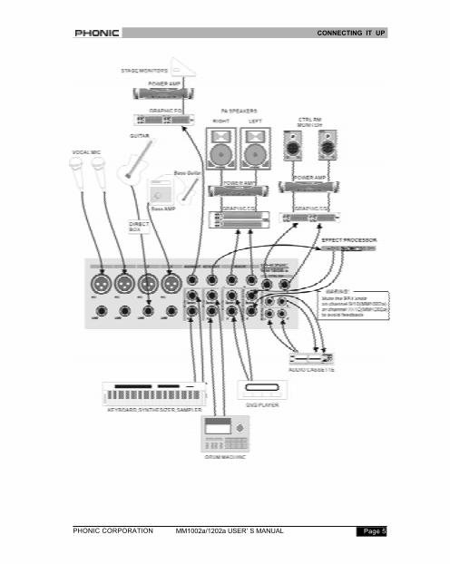
CONNECTING IT UP
PHONIC CORPORATIONPage 6 MM1002a/1202a USER’ S MANUAL
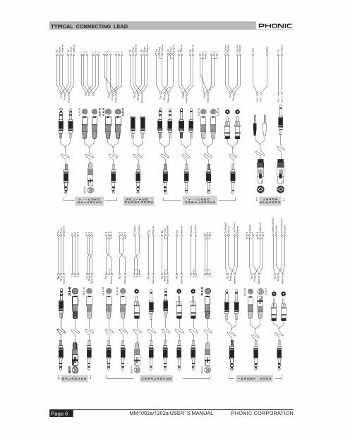
TYPICAL CONNECTING LEAD
PHONIC CORPORATION Page 7MM1002a/1202a USER’ S MANUAL
UNBALANCED & BALANCED
Most of the mistakes in audio installations are due
to incorrect and/or defective audio connections. In
order to perfectly complete your installation, please
pay special attention to the following section unless
you are already familiar with balanced/unbalanced
operations.
WHAT IS AN UNBALANCED LINE?
You can find this kind of system in most of home
audio-video systems. They have one conductor to
carry signal, and another conductor for a ground.
Normally, for lower level signals, the ground con-
ductor shields the signal conductor.
WHAT IS A BALANCED LINE?
A balanced system transmits signal via two con-
ductors plus one ground shielding conductor. The
two signal conductors carry the same signal but out
of phase. For the balanced input stage, the ampli-
fier will boost the difference between the two signal
conductors and remove the identical part (known
as common mode signal) of the two signals. Be-
cause the real signal is carried by the two conduc-
tors out of phase, so it is perfectly carried to the
input. At the same time, interference that occurs
during transmission will be identical (common
mode). Because the signal conductors are run to-
gether, there is no chance they can be different,
and all the interference will be removed by the bal-
anced input amplifier.
THE DIFFERENCE BETWEEN TWO
OPERATIONS
Because of the common mode interference immu-
nity of a balanced system, the ground conductor
does not need to carry any electrical current, which
means the ground of the two connected units has
an identical ground level which is vital to an inter-
ference free system. Let us look back at the unbal-
anced system. The signal electrical current goes
from the signal conductor to the ground conductor.
The ground level of the two connected units are not
identical. This means the system is more easily in-
clined to noise interference.
Running long cables is easy for a balanced system
but difficult for an unbalanced one. A Lower noise
level is a characteristic of a balanced system.
Because a balanced system needs two conductors
for the signal and one conductor for the ground, a
minimum of three conductors are needed for wir-
ing a balanced system. Therefore, a dedicated sys-
tem separates the ground and shields the two con-
ductors.
Please read following section to properly wire for
balanced and unbalanced systems:
THE CORRECT WIRING FOR BALANCED
OPERATION
Always connect the main power with three plugs.
Make sure the power system ground is working
properly. Do not use a ground insulator plug adapter
without properly connecting the ground individually.
This is vital to making a successful audio system
connection.
Always connect the ground pin (PIN 1 in XLR) to
the source unit, and disconnect this pin on the des-
tination unit. This connection topology is to avoid
creating a grounding loop between the signal and
power ground. Utilize only the power ground, be-
UNBALANCED & BALANCED
PHONIC CORPORATIONPage 8 MM1002a/1202a USER’ S MANUAL
cause it always has a lower resis-
tance and better distribution than the
signal ground.
If there is hum, one possible reason
is a bad ground connection for the
system. In case you cannot find the
fault, try connecting the ground pin
of the input connectors. If the hum is
reduced or eliminated, check your
power grounding system. Special at-
tention is needed when you use the
equipment racks with some distance
between them, and/or use a large
quantity of power amplifiers. Check
the power ground between the racks
and power distribution strips with
your electrical supply engineer. Make
sure there is one, and only one,
proper ground point for the audio
system (or connected video system).
INPUT CHANNEL
DESCRIPTION
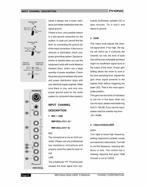
1 MIC / LINE
MM1002a (Ch1~2) /
MM1202a (Ch1~4)
MIC
The microphone is via an XLR con-
nector. Please use only professional
low impedance microphone and
properly wired the cable for best re-
sult.
LINE
The unbalanced 1/4" TS phone jack
accepts line level signal from key-
boards, synthesizer, sampler, CD, or
tape recorder. Tip is hot(+) and
sleeve is ground.
2 GAIN
This rotary knob adjusts the chan-
nel signal level. If too high, the sig-
nal will distort as it overloads the
channel; too low, the level of back
hiss will be even noticeable and there
might be insufficient signal level to
the output of the mixer. Proper gain
setting allows the mixer to work in
the best operating level, adjusts the
gain when signal presents to the
highest level without triggering the
peak LED. That is the most appro-
priate position.
This gain has two kinds of indication
to suit mic or line input, when you
use mic input, please read inside ring
from 0~+60 dB, if you use line input,
please read the outside ring from
-20~+40dB.
3 3-Band EQUALIZER
HIGH
Turn right to boost high frequency,
adding crispness to cymbals, vocals
and electronic instruments. Turn left
to cut this frequency, reducing sibi-
lance or hiss. The control has a
shelving response that gives 15dB
of boost or cut at 12KHZ.
INPUT CHANNEL DESCRIPTION
PHONIC CORPORATION Page 9MM1002a/1202a USER’ S MANUAL
MID
The knob provides 15dB of boost or
cut at 2.5KHz, just like the HF EQ
knob. The mid band covers the range
for most vocals. Listen carefully
when using this control and find how
particular characteristics of vocal or
guitar signal can be enhanced or re-
duced .Set the upper knob in the 0
position when not required.
LOW
The control has shelving response
that gives 15dB of boost or cut at
80Hz. Adding warmth to vocals or
extra punch to guitars, drums and
synths by turning to the right. Turn
left to reduce stage rumble, hum or
to improve a mushy sound.
These equalizers are designed to ac-
commodate different room acous-
tics, feedback control and to improve
live PA sound. No amount of equal-
ization will correct the frequency re-
sponse curve of a poor loudspeaker,
however. Always begin with all con-
trol at the 0position and avoid exces-
sively cutting/boosting large seg-
ments of the peculiar frequency.
Thus, would limit the system dy-
namic range or increase the possi-
bility of the unpleasant feedback
sound. To make sound more impres-
sive, dynamic process is necessary.
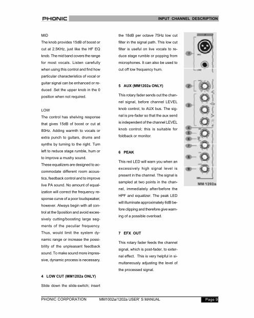
4 LOW CUT (MM1202a ONLY)
Slide down the slide-switch; insert
the 18dB per octave 75Hz low cut
filter in the signal path. This low cut
filter is useful on live vocals to re-
duce stage rumble or popping from
microphones. It can also be used to
cut off low frequency hum.
5 AUX (MM1202a ONLY)
This rotary fader sends out the chan-
nel signal, before channel LEVEL
knob control, to AUX bus. The sig-
nal is pre-fader so that the aux send
is independent of the channel LEVEL
knob control; this is suitable for
foldback or monitor.
6 PEAK
This red LED will warn you when an
excessively high signal level is
present in the channel. The signal is
sampled at two points in the chan-
nel, immediately after/before the
HPF and equalizer. The peak LED
will illuminate approximately 6dB be-
fore clipping and therefore give warn-
ing of a possible overload.
7 EFX OUT
This rotary fader feeds the channel
signal, which is post-fader, to exter-
nal effect. This is very helpful in si-
multaneously adjusting the level of
the processed signal.
INPUT CHANNEL DESCRIPTION
PHONIC CORPORATIONPage 10 MM1002a/1202a USER’ S MANUAL
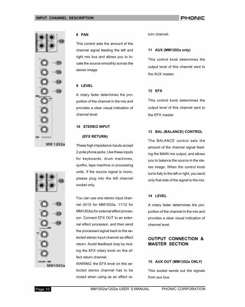
8 PAN
This control sets the amount of the
channel signal feeding the left and
right mix bus and allows you to lo-
cate the source smoothly across the
stereo image.
9 LEVEL
A rotary fader determines the pro-
portion of the channel in the mix and
provides a clear visual indication of
channel level.
10 STEREO INPUT
(EFX RETURN)
These high impedance inputs accept
2-pole phone jacks. Use these inputs
for keyboards, drum machines,
synths, tape machine or processing
units. If the source signal is mono,
please plug into the left channel
socket only.
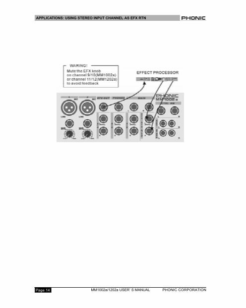
You can use one stereo input chan-
nel (9/10 for MM1002a, 11/12 for
MM1202a) for external effect proces-
sor. Connect EFX OUT to an exter-
nal effect processor, and then send
the processed signal back to the se-
lected stereo input channel as effect
return. Avoid feedback loop by mut-
ing the EFX rotary knob on this ef-
fect return channel.
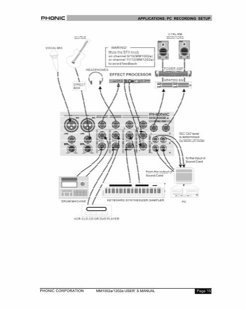
WARING: the EFX knob on this se-
lected stereo channel has to be
muted when using as an effect re-
turn channel.
11 AUX (MM1202a only)
This control knob determines the
output level of this channel sent to
the AUX master.
12 EFX
This control konb determines the
output level of this channel sent to
the EFX master.
13 BAL (BALANCE) CONTROL
The BALANCE control sets the
amount of the channel signal feed-
ing the MAIN mix output, and allows
you to balance the source in the ste-
reo image. When the control knob
turns fully to the left or right, you send
only that side of the signal to the mix.
14 LEVEL
A rotary fader determines the pro-
portion of the channel in the mix and
provides a clear visual indication of
channel level.
OUTPUT CONNECTION &
MASTER SECTION
15 AUX OUT (MM1202a ONLY)
This socket sends out the signals
from aux bus.
INPUT CHANNEL DESCRIPTION
PHONIC CORPORATION Page 11MM1002a/1202a USER’ S MANUAL
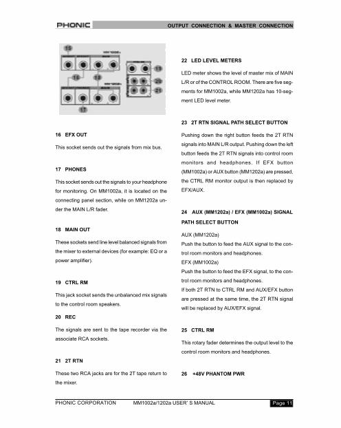
16 EFX OUT
This socket sends out the signals from mix bus.
17 PHONES
This socket sends out the signals to your headphone
for monitoring. On MM1002a, it is located on the
connecting panel section, while on MM1202a un-
der the MAIN L/R fader.
18 MAIN OUT
These sockets send line level balanced signals from
the mixer to external devices (for example: EQ or a
power amplifier).
19 CTRL RM
This jack socket sends the unbalanced mix signals
to the control room speakers.
20 REC
The signals are sent to the tape recorder via the
associate RCA sockets.
21 2T RTN
These two RCA jacks are for the 2T tape return to
the mixer.
22 LED LEVEL METERS
LED meter shows the level of master mix of MAIN
L/R or of the CONTROL ROOM. There are five seg-
ments for MM1002a, while MM1202a has 10-seg-
ment LED level meter.
23 2T RTN SIGNAL PATH SELECT BUTTON
Pushing down the right button feeds the 2T RTN
signals into MAIN L/R output. Pushing down the left
button feeds the 2T RTN signals into control room
monitors and headphones. If EFX button
(MM1002a) or AUX button (MM1202a) are pressed,
the CTRL RM monitor output is then replaced by
EFX/AUX.
24 AUX (MM1202a) / EFX (MM1002a) SIGNAL
PATH SELECT BUTTON
AUX (MM1202a)
Push the button to feed the AUX signal to the con-
trol room monitors and headphones.
EFX (MM1002a)
Push the button to feed the EFX signal, to the con-
trol room monitors and headphones.
If both 2T RTN to CTRL RM and AUX/EFX button
are pressed at the same time, the 2T RTN signal
will be replaced by AUX/EFX signal.
25 CTRL RM
This rotary fader determines the output level to the
control room monitors and headphones.
26 +48V PHANTOM PWR
OUTPUT CONNECTION & MASTER CONNECTION
PHONIC CORPORATIONPage 12 MM1002a/1202a USER’ S MANUAL
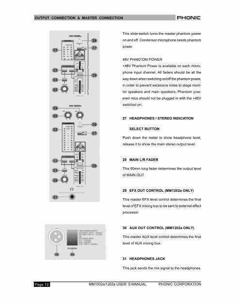
This slide-switch turns the master phantom power
on and off. Condensor microphone needs phantom
power.
48V PHANTOM POWER
+48V Phantom Power is available on each micro-
phone input channel. All faders should be all the
way down when switching on/off the phantom power,
in order to prevent excessive noise to stage moni-
tor speakers and main speakers; Phantom pow-
ered mics should not be plugged in with the +48V
switched on.
27 HEADPHONES / STEREO INDICATION
SELECT BUTTON
Push down the meter to show headphone level,
release it to show the main stereo output level.
28 MAIN L/R FADER
This 60mm long fader determines the output level
of MAIN OUT.
29 EFX OUT CONTROL (MM1202a ONLY)
This master EFX level control determines the final
level of EFX mixing bus to be sent to external effect
processor.
30 AUX OUT CONTROL (MM1202a ONLY)
This master AUX level control determines the final
level of AUX mixing bus.
31 HEADPHONES JACK
This jack sends the mix signal to the headphones.
OUTPUT CONNECTION & MASTER CONNECTION
PHONIC CORPORATION Page 13MM1002a/1202a USER’ S MANUAL
32 POWER SUPPLY INPUT SOCKET
Connect the power supply unit to this socket. Make
sure the power supply unit is not plugged into AC
outlet before connecting to the mixer.
33 POWER ON/OFF SWITCH
This switch turns the power of the unit on and off.
To prevent this unit from damaging, move the MAIN
L/R fader all the way down before turning the power.
INITIAL SETUP
The procedure is very important. Even if you do not
like to read manuals, please read this section. Af-
ter you have connected the system, you can begin
the initial set up for every input channel. The match-
ing of every input gain to the signal source is cru-
cial. Every detail affects the final output of the mixer.
Basically, input sensitivity adjustment, channel fader,
and output fader are the main factors. You should
try to set only as much microphone gain as required
to achieve a good balance between signals. If the
input gain is set too low, you will not get enough
gain on the faders to push the signal up to an ad-
equate level. If the input gain is set too high, the
channel fader will need to be pulled down in com-
pensation, leaving greater risk of feedback because
a small fader movement will have a very significant
effect on output level. Certainly, the limited fader
travel path will not be successful in the mixing pro-
cedure. Please use the following set up procedure.
Do not turn the output up until they clip and then
backing off.
FOLLOW THE PROCEDURE FOR EACH
CHANNEL IN USE
• Set all faders and gain controls all the way off.
• Phantom powered microphone should be con-
nected before the +48V is switched on.
• Set power amplifier levels to 70%.
• Set the CTRL RM Level and Headphone level
to about 50%.
• If you want to hear what you are doing, plug
your headphone into the phone output socket,
or hook up your control room amplifier sys-
tem to the Control Room outputs.
• Set EQ control at center position.
• Set PAN and BALANCE knobs at center po-
sition.
• You need a headphone to continue.
• Apply a typical performance level signal, moni-
toring the level on the LED meter.
• Adjust the input gain until the meter shows in
the amber section, with occasional peaks to
the first red LED at maximum source level.
This allows enough headroom to accommo-
date peaks and the maximum level for nor-
mal operation; you can listen to them through
your headphone.
• For microphone sources, the gain control ad-
justment will depend on the kind of the micro-
phone in use. Normally turn the gain clock-
wise around 2~3 clock position. Ask the
singer to perform aloud and do not whisper. If
they do not sing at a normal level while you
are doing the sound check, you might drive
the mixer to overload or produce feedback by
setting the gain too high during the initial set
up.
• Repeat this procedure for all other channels.
When more channels are added to the mixer,
the meters LED may move up to the red sec-
tion. Adjust the overall level using the master
faders if necessary.
INITIAL SETUP
PHONIC CORPORATIONPage 14 MM1002a/1202a USER’ S MANUAL
APPLICATIONS: USING STEREO INPUT CHANNEL AS EFX RTN
PHONIC CORPORATION Page 15MM1002a/1202a USER’ S MANUAL
APPLICATIONS: PC RECORDING SETUP

PHONIC CORPORATIONPage 16 MM1002a/1202a USER’ S MANUAL
DEMINSIONS
Measurements are shown in mm / inch

PHONIC CORPORATION Page 17MM1002a/1202a USER’ S MANUAL
SPECIFICATIONS
PHONIC CORPORATIONPage 18 MM1002a/1202a USER’ S MANUAL
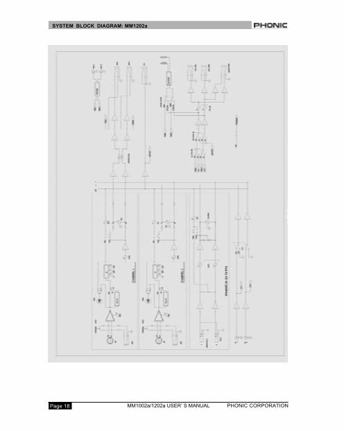
SYSTEM BLOCK DIAGRAM: MM1202a

PHONIC CORPORATION Page 19MM1002a/1202a USER’ S MANUAL
SYSTEM BLOCK DIAGRAM: MM1002a