October 2019 UM1913 Rev 8 1/149 1 UM1913 User manual Developing applications on STM32Cube with STMTouch touch sensing library Introduction STM32Cube is an STMicroelectronics original initiative to improve developer productivity by reducing development effort, time and cost. STM32Cube covers the STM32 portfolio. STM32Cube includes STM32CubeMX, configuration tool that allows the generation of C initialization code and an embedded software platform, delivered per STM32xx Series: • the STM32Cube HAL, STM32 abstraction layer embedded software ensuring maximized portability across the STM32 portfolio • a consistent set of middleware components such as RTOS, USB, TCP/IP, Graphics and STMTouch • all embedded software utilities coming with a full set of examples This user manual describes the STMTouch touch sensing library that is part of the STM32Cube firmware package, available from the STMicroelectronics website (http://www.st.com/stm32cube). It is intended for developers who use STM32Cube firmware on STM32 Arm ® -based microcontrollers listed in the table below. The STMTouch touch sensing library (TSL) includes: • a complete register address mapping with all bits, bitfields and registers declared in C • a collection of routines and data structures covering all functions to manage the touch sensing technology The source code is developed using the ANSI-C standard. It is fully documented and is MISRA C ® 2004 compliant. Writing the whole library in 'Strict ANSI-C' makes it independent from the development tools. Only the start-up files depend on the development tools. Since this library is generic and covers many functionalities and microcontrollers, the size and/or execution speed of the application code may not be optimized. For many applications, this library may be used as is. However, for applications having tough constraints in terms of code size and/or execution speed, this library may need to be fine tuned. Table 1. Applicable products Type Software package (associated STM32 Series) STM32Cube package STM32CubeF0, STM32CubeF3 (STM32F0/F3) STM32CubeL0, STM32CubeL1, STM32CubeL4 (STM32L0/L1/L4/L4+) STM32CubeWB (STM32WB) www.st.com
Transcript
October 2019 UM1913 Rev 8 1/149
1
UM1913User manual
Developing applications on STM32Cube with STMTouch touch sensing library
Introduction
STM32Cube is an STMicroelectronics original initiative to improve developer productivity by reducing development effort, time and cost. STM32Cube covers the STM32 portfolio.
STM32Cube includes STM32CubeMX, configuration tool that allows the generation of C initialization code and an embedded software platform, delivered per STM32xx Series:
• the STM32Cube HAL, STM32 abstraction layer embedded software ensuring maximized portability across the STM32 portfolio
• a consistent set of middleware components such as RTOS, USB, TCP/IP, Graphics and STMTouch
• all embedded software utilities coming with a full set of examples
This user manual describes the STMTouch touch sensing library that is part of the STM32Cube firmware package, available from the STMicroelectronics website (http://www.st.com/stm32cube). It is intended for developers who use STM32Cube firmware on STM32 Arm®-based microcontrollers listed in the table below.
The STMTouch touch sensing library (TSL) includes:
• a complete register address mapping with all bits, bitfields and registers declared in C
• a collection of routines and data structures covering all functions to manage the touch sensing technology
The source code is developed using the ANSI-C standard. It is fully documented and is MISRA C® 2004 compliant. Writing the whole library in 'Strict ANSI-C' makes it independent from the development tools. Only the start-up files depend on the development tools. Since this library is generic and covers many functionalities and microcontrollers, the size and/or execution speed of the application code may not be optimized. For many applications, this library may be used as is. However, for applications having tough constraints in terms of code size and/or execution speed, this library may need to be fine tuned.
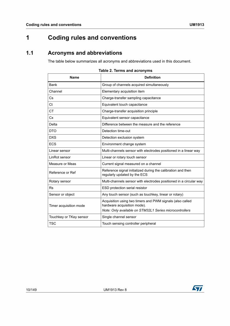
The table below summarizes all acronyms and abbreviations used in this document.
Table 2. Terms and acronyms
Name Definition
Bank Group of channels acquired simultaneously
Channel Elementary acquisition item
Cs Charge-transfer sampling capacitance
Ct Equivalent touch capacitance
CT Charge-transfer acquisition principle
Cx Equivalent sensor capacitance
Delta Difference between the measure and the reference
DTO Detection time-out
DXS Detection exclusion system
ECS Environment change system
Linear sensor Multi-channels sensor with electrodes positioned in a linear way
LinRot sensor Linear or rotary touch sensor
Measure or Meas Current signal measured on a channel
Reference or RefReference signal initialized during the calibration and then regularly updated by the ECS
Rotary sensor Multi-channels sensor with electrodes positioned in a circular way
Rs ESD protection serial resistor
Sensor or object Any touch sensor (such as touchkey, linear or rotary)
Timer acquisition modeAcquisition using two timers and PWM signals (also called hardware acquisition mode).
Note: Only available on STM32L1 Series microcontrollers
Touchkey or TKey sensor Single channel sensor
TSC Touch sensing controller peripheral
UM1913 Rev 8 11/149
UM1913 Coding rules and conventions
148
1.2 Naming conventions
The following naming conventions are used in the STMTouch touch sensing library source files:
• Source and header files are in lower-case and preceded by 'tsl' or 'tsl_'.
• The microcontroller family is added at the end of the file name if needed.
• Functions, globals, typedefs and defines are preceded by 'TSL'.
• Constants are written in upper case and preceded by 'TSLPRM_'.
• Constants used in one file are defined within this file only.
• Constants used in more than one file are defined in a header file.
• Typedef names are suffixed with '_T'.
• Enum typedefs are suffixed with '_enum_T'.
• Functions are named according to the 'TSL_[module]_[function]' scheme:
– [module]: abbreviation of the file (such as acq, tim, dxs)
– [function]: the first letter in each word is in upper case.
1.3 Coding rules
This section describes the coding rules used in the STMTouch touch sensing library source files.
1.3.1 General
• Source code complies with ANSI C standard.
• No warning after compilation. Any warning that cannot be eliminated is commented in the source code.
• ANSI standard data types are used and defined in the ANSI C header file <stdint.h>.
• No blocking code is present and all required waiting loops (polling loops) are controlled by a timeout.
1.3.2 Variable types
Specific variable types are already defined with a fixed type and size:
• The types that are used by all modules are defined in the tsl_types.h file.
• Other variable types are defined in their corresponding module header file.
1.3.3 Peripheral registers
The peripheral registers are accessed using the pointers described in the CMSIS device peripheral access layer header file.
Coding rules and conventions UM1913
12/149 UM1913 Rev 8
1.4 MISRA C 2004 compliance
1.4.1 Generalities
The C programming language importance grows for embedded systems. However, when it comes to developing code for safety-critical applications, this language has many drawbacks. There are several unspecified, implementation-defined, and undefined aspects of the C language that make it unsuited for developing safety-critical systems.
The motor industry software reliability association describes a subset of the C language well suited for developing safety-critical systems in [1].
The STMTouch touch sensing library has been developed to be MISRA C 2004 compliant.
The following section describes how the STMTouch touch sensing library complies with MISRA C 2004 (as described in section 4.4 Claiming compliance of the standard of [1]:
• A compliance matrix has been completed which shows how compliance has been enforced.
• The whole STMTouch touch sensing library source code is compliant with MISRA C 2004 rules.
• Deviations are documented. A list of all instances of rules not being followed is being maintained, and for each instance there is an appropriately signed-off deviation.
• All the issues listed in section 4.2, The programming language and coding context of the standard of [1], that need to be checked during the firmware development phase, have been addressed during the development of the STMTouch touch sensing library and appropriate measures have been taken.
1.4.2 Compliance matrix
The compliance of the STMTouch touch sensing library with MISRA C 2004 has been checked in two ways:
• using PC-lint tool for C/C++ (NT) versus 8.00v, copyright gimpel software 1985-2006
• performing regular code reviews
The following table lists the MISRA C 2004 rules that are frequently violated in the code:
Table 3. MISRA C 2004 rules not followed
MISRA C 2004 rule number
Required/advisory
Summary Reason of deviance
1.1
1.2Required
All code must conform to ISO 9899:1990 standard C, with no extensions permitted.
Compilers extensions are enabled. Comments starting with “//” symbol for code readability.
5.4 RequiredA tag name must be a unique identifier.
Due to the usage of objects methods
8.1 Required
No prototype seen. Functions must always have prototype declarations and the prototype must be visible at both the function definition.
This rule is violated as there is no functions prototypes for the objects methods.
UM1913 Rev 8 13/149
UM1913 Coding rules and conventions
148
10.1
10.2Required
The value of an expression of integer/floating type must not be implicitly converted to a different underlying type.
Code complexity
10.3 Required
The value of a complex expression of integer type may only be cast to a type that is narrower and of the same signedness as the underlying type of the expression.
Code complexity
10.5 Required
If the bitwise operators are applied to an operand of underlying type unsigned char or unsigned short, the result must be immediately cast to the underlying type of the operand.
Use shift on signed quantity for the linear/rotary position
11.3 AdvisoryA cast must not be performed between a pointer type and an integral type.
Needed when addressing memory mapped registers
12.7 RequiredBitwise operators must not be applied to operands whose underlying type is signed.
Shift of signed value needed
14.3 RequiredBefore preprocessing, a null statement must only occur on a line by itself.
Use of macros to simplify the code
14.5 RequiredThe continue statement must not be used.
Used to optimize the code speed execution
19.11 Required
All macro identifiers in preprocessor directives must be defined before use, except in ifdef and ifndef preprocessor directives and the defined() operator.
All parameters are checked in the check_config files
Table 3. MISRA C 2004 rules not followed (continued)
MISRA C 2004 rule number
Required/advisory
Summary Reason of deviance
STMTouch touch sensing library UM1913
14/149 UM1913 Rev 8
2 STMTouch touch sensing library
2.1 Supported microcontrollers and development tools
2.1.1 Supported microcontrollers
This STMTouch touch sensing library version supports the following microcontrollers and acquisition modes:
• Any STM32 microcontroller using the embedded touch sensing controller (TSC): all Arm®(a)-based devices (see Table 1):
– Surface charge-transfer acquisition principle managed by the touch sensing controller
– Up to 24 channels (eight groups of three channels maximum)
– Up to eight channels can be acquired simultaneously
– Spread spectrum feature
– Programmable charge transfer frequency and max count value
• STM32L1 Series microcontrollers: the surface charge-transfer acquisition principle is managed by:
– Two timers plus a routing interface (hardware acquisition mode). This mode is not supported on STM32L1 Series microcontrollers featuring 256-Kbyte or less memory.
– GPIOs plus a routing interface (software acquisition mode). This mode is supported by all microcontrollers.
– Up to 34 channels
– Up to 11 channels can be acquired simultaneously
2.1.2 Development tools
The STM32 microcontrollers are supported by a full range of development solutions from lead suppliers that deliver start-to-finish control of application development from a single integrated development environment.
The STMTouch touch sensing library has been developed with the following toolchains:
• EWARM (IAR™)
• MDK-ARM (Keil®)
• SW4STM32 (AC6)
For more details about the compilers versions used, see the STM32Cube package release note.
a. Arm is a registered trademark of Arm Limited (or its subsidiaries) in the US and/or elsewhere.
UM1913 Rev 8 15/149
UM1913 STMTouch touch sensing library
148
2.2 Package description
The following snapshots show an example of installation inside the STM32CubeF0 package.
The STMTouch touch sensing library is composed of the following main layers:
• acquisition layer
• processing layer
• configuration layer
The configuration layer corresponds to what the user needs to write in his application code in order to correctly use the STMTouch touch sensing library. This includes all the channels and sensors declarations and the parameters for example.
The acquisition and processing layers are described in more details below.
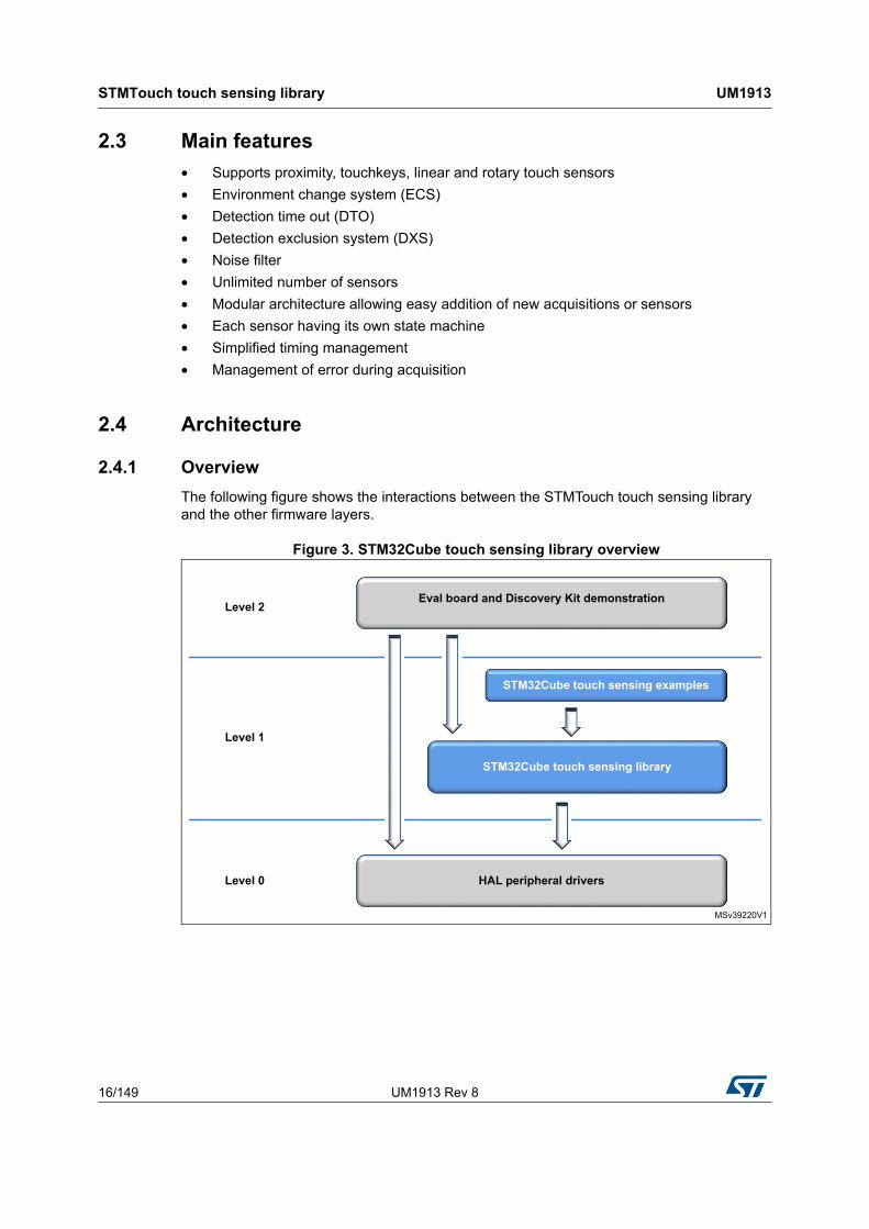
The following figure details the acquisition and processing layers and the different elements used in each layer.
Figure 5. Acquisition and processing layers
The acquisition layer role is to perform the acquisition of the different channels. The result of the acquisition (measure and flags) is stored inside the channel data layer. These informations are accessed by the processing layer.
The acquisition layer has only access to the channels and banks. It does not have access to the sensors.
The channel data layer role is to share information between the acquisition and processing layers. It stores the result of the acquisition (measure) for each channel and store different informations coming from the processing layer (such as reference, delta or flags).
Located in RAM, the ChannelData structure is the only interface between the acquisition and processing layers.
This processing layer consists in executing each sensors state machine, executing the different data processing like ECS, DXS, DTO and storing any useful information for the acquisition layer inside the channel data area.
The processing layer does not have direct access to the channels and banks. This access is made through the sensors.
MSv31730V2
ECSDXSDTO
FiltersTiming
...
Processinglayer
= touchkey = linear / rotary
= sensors
Acquisition layer
Channel data layer
= channel = bank
UM1913 Rev 8 19/149
UM1913 STMTouch touch sensing library
148
2.4.4 Header files inclusion
The figure below provides a global view of the STMTouch touch sensing library usage and the interaction between the different header files.
In the actual version of the STMTouch touch sensing library, the <XXX> is equal to “tsc” or “stm32l1xx”.
Note: To simplify the drawing, only the most important links are shown. For example the tsl_globals.h file is also included in different files.
Figure 6. Header files inclusion
2.5 Channel
2.5.1 Principle
A channel is the basic element that is used to store several information like:
• where the source measurement can be found after the acquisition is performed (TSC_IOGxCR registers for TSC acquisition)
• where are stored the measure, the reference, the delta or the flags
MSv39222V1
Application layer
STM32Cube touch sensing
library
main.h
tsl.h
tsl_check_config.h
tsl_check_config_<XXX>.h
tsl_filter.h
tsl_ecs.h
tsl_object.h
tsl_acq.h
tsl_time.htsl_types.h
tsl_globals.h
stm32xxx.h (hardware registers mapping file)
tsl_dxs.h
tsl_linrot.h
tsl_touchkey.h
tsl_acq_<XXX>.h
tsl_time_<XXX>.h
tsl_conf.h
STMTouch touch sensing library UM1913
20/149 UM1913 Rev 8
2.5.2 Resources
A channel is defined by the following data structures:
• TSL_ChannelSrc_T: contains all information about the source measurement (such as index of the register containing the measurement or masks)
• TSL_ChannelDest_T: contains all information about the measurement destination (index in the channel data array).
• TSL_ChannelData_T: contains all data for the channel (such as measure, delta or reference)
The channel depends on the acquisition technology. This is why the contents of this structures are not common for all acquisitions. They are declared in each acquisition header files (tsl_acq_<XXX>.h):
• tsl_acq_stm32l1xx_hw.h for STM32L1 Series microcontrollers using the hardware acquisition mode
• tsl_acq_stm32l1xx_sw.h for STM32L1 Series microcontrollers using the software acquisition mode
• tsl_acq_tsc.h for any STM32 microcontrollers featuring the TSC peripheral
The maximum number of channels is only limited by the device (memory size and channels supported).
The user must declare all the channels arrays in his application code. It can be done directly in the main.c file or in any other file.
2.5.3 Parameters
• TSLPRM_TOTAL_CHANNELS
2.5.4 Usage example
The channels structures must be declared in the application code.
Example of channel source array declaration for microcontrollers featuring TSC peripheral. This structure must always be placed in ROM.
A bank is a group of channels that are acquired simultaneously. The number of channels in the bank is variable.
2.6.2 Resources
The bank data are held by only one structure: TSL_Bank_T
MSv31732V1
Bank1 Bank2
CH0 CH1 CH2 CH3 CH4 CH5 CH6Channel data layer
STMTouch touch sensing library UM1913
22/149 UM1913 Rev 8
The bank depends also on the acquisition technology. Structures are declared in each acquisition header files (tsl_acq_<XXX>.h):
The maximum number of banks is only limited by the device.
The user must declare all the bank arrays in his application code. It can be done directly in the main.c file or in any other file.
The banks are used mainly by the functions described below. Some functions are common whatever the device and acquisition technology. Some others are dependent on the device.
Common functions:
• TSL_acq_BankGetResult()
• TSL_acq_BankCalibrate()
Device dependent functions:
• TSL_acq_BankConfig()
• TSL_acq_BankStartAcq()
• TSL_acq_BankWaitEOC()
2.6.3 Parameters
• TSLPRM_TOTAL_BANKS
2.6.4 Usage example
Example of three banks declaration for microcontrollers featuring TSC peripheral:
The term “object” or “sensor” stands for any sensor type (touchkeys, linear and rotary touch sensors) supported by the STMTouch touch sensing library.
2.7.2 Resources
All processing that affect the sensors in general are defined in the following files:
• tsl_object.c
• tsl_object.h
UM1913 Rev 8 23/149
UM1913 STMTouch touch sensing library
148
The functions are:
• TSL_obj_GroupInit()
• TSL_obj_GroupProcess()
• TSL_obj_SetGlobalObj()
A sensor is described by the structures:
• TSL_Object_T
• TSL_ObjectGroup_T
2.7.3 Parameters
• TSLPRM_TOTAL_OBJECTS
2.7.4 Example
First, all touchkeys, linear and rotary touch sensors (described after) used in the application must be described first as 'generic' sensors or objects.
Once this is done, it is necessary to create at least one group of sensors. Groups of sensors are used by the different processing routines (such as ECS or DXS).
These groups of objects must be placed in the RAM.
Example:
TSL_ObjectGroup_T MyObjGroup_All = {
MyObjects,
3,
0,
TSL_STATE_NOT_CHANGED
};
Then, all the sensors must be initialized and “processed”. This is done in the main function of the application:
int main(void) {
...
TSL_obj_GroupInit(&MyObjGroup_All);
...
while (1) {
STMTouch touch sensing library UM1913
24/149 UM1913 Rev 8
...
TSL_obj_GroupProcess(&MyObjGroup_All);
...
}
}
2.8 Touchkey sensor
2.8.1 Principle
The touchkey sensor is composed of only one channel. It acts as a simple “button” with two states RELEASE and DETECT (or TOUCH if DXS is enabled).
2.8.2 Resources
All the functions related to this sensor are described in the files:
• tsl_touchkey.c
• tsl_touchkey.h
Two types of touchkey sensor are available:
• Basic: defined by the TSL_TouchKeyB_T structure
• Extended: defined by the TSL_TouchKey_T structure
Two functions (called methods) are used to initialize the sensor parameters and to run the sensor state machine:
• TSL_tkey_Init()
• TSL_tkey_Process()
The difference between the basic and extended types concerns the methods and sensor state machine used:
• For a basic sensor, the methods and state machine are those used in the TSL_Params structure.
• For an extended sensor, the methods and state machine are those declared in their own structure.
2.8.3 Parameters
• TSLPRM_TOTAL_TKEYS
2.8.4 Usage example
The user must declare these methods in the application code.
Note: User own initialization and process functions can also be used instead:
const TSL_TouchKeyMethods_T MyTKeys_Methods =
{
TSL_tkey_Init,
TSL_tkey_Process
};
UM1913 Rev 8 25/149
UM1913 STMTouch touch sensing library
148
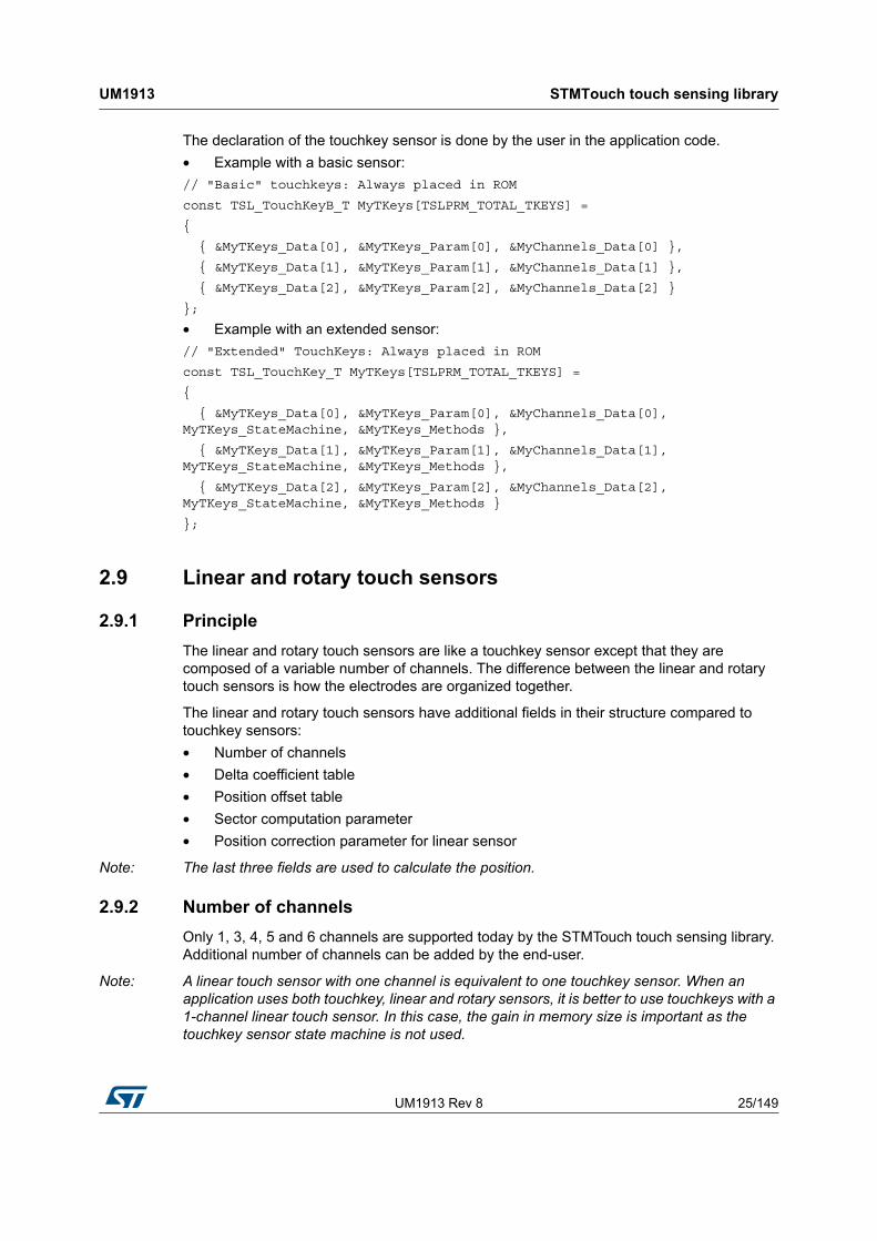
The declaration of the touchkey sensor is done by the user in the application code.
The linear and rotary touch sensors are like a touchkey sensor except that they are composed of a variable number of channels. The difference between the linear and rotary touch sensors is how the electrodes are organized together.
The linear and rotary touch sensors have additional fields in their structure compared to touchkey sensors:
• Number of channels
• Delta coefficient table
• Position offset table
• Sector computation parameter
• Position correction parameter for linear sensor
Note: The last three fields are used to calculate the position.
2.9.2 Number of channels
Only 1, 3, 4, 5 and 6 channels are supported today by the STMTouch touch sensing library. Additional number of channels can be added by the end-user.
Note: A linear touch sensor with one channel is equivalent to one touchkey sensor. When an application uses both touchkey, linear and rotary sensors, it is better to use touchkeys with a 1-channel linear touch sensor. In this case, the gain in memory size is important as the touchkey sensor state machine is not used.
STMTouch touch sensing library UM1913
26/149 UM1913 Rev 8
2.9.3 Delta coefficient table
The delta coefficient table is used to adjust each channel of the linear and rotary touch sensors. Each value is a 16-bit integer. The MSB is the integer part, the LSB is the real part.
Examples:
• To apply a factor of 1.10:
– MSB equal 0x01
– LSB equal 0x1A (0.10 x 256 = 25.6, rounded to 26 = 0x1A)
• To apply a factor 1.00:
– MSB equal 0x01
– LSB equal 0x00
• To apply a factor 0.90:
– MSB equal 0x00
– LSB equal 0xE6 (0.90 x 256 = 230.4, rounded to 230 = 0xE6)
This results in the following delta coefficient table:
The number of delta coefficient table is not limited. The same delta coefficient table can be shared by several linear and rotary touch sensors.
2.9.4 Electrodes placement
The placement (design) of the electrodes can be done in three different manners:
• Mono electrode design
The number of electrodes is equivalent to the number of channels. This design is used for linear and rotary touch sensors.
Abbreviations: LIN_M1, LIN_M2 and ROT_M
Examples:
– CH1 CH2 CH3
– CH1 CH2 CH3 CH4
– CH1 CH2 CH3 CH4 CH5
• Dual electrode design
All the electrodes are duplicated and interlaced together in order to increase the touch area.
This design is used for linear and rotary touch sensors composed with at least five channels.
Abbreviation: ROT_D
Examples with 5 channels:
– CH1 CH2 CH3 CH4 CH5 CH1 CH3 CH5 CH2 CH4
– CH1 CH2 CH3 CH4 CH5 CH2 CH4 CH1 CH3 CH5
– CH1 CH2 CH3 CH4 CH5 CH3 CH1 CH4 CH2 CH5
• Half-ended electrode design
The first electrode is duplicated and the replica is placed at the end. The size of the first and last electrode is half the size of the other electrodes. This design is used for linear
UM1913 Rev 8 27/149
UM1913 STMTouch touch sensing library
148
sensors only. The 0 and 255 positions are obtained more easily compared to the Mono electrodes design.
Abbreviation: LIN_H
Examples:
– ch1 CH2 CH3 ch1
– ch1 CH2 CH3 CH4 ch1
– ch1 CH2 CH3 CH4 CH5 ch1
The following figure summarizes the different electrodes designs we can have on linear and rotary touch sensors:
Figure 8. Electrodes designs
Positions 0 and 255
Special care must be taken for the 0 and 255 positions on linear sensors. These positions are placed differently depending on the electrodes design used:
• LIN_M1: the 0 and 255 positions are placed completely at the sensor's extremities. These positions can be obtain with difficulty if the electrodes are too big or if they are separated by an important space.
• LIN_M2, LIN_H: the 0 position is placed between the first and second electrodes. The 255 position is placed between the last two electrodes.
• ROT_M and ROT_D: the 0 and 255 positions are always placed between the first and the last electrodes.
MSv31733V2
ch1 CH2 CH3 ch1
CH1 CH2 CH3
ROT_D
ROT_MLIN_M1LIN_M2
-Dual
electrodes design
Half-endedelectrodes
design
Monoelectrodes
design
Linear Rotary
LIN_H
STMTouch touch sensing library UM1913
28/149 UM1913 Rev 8
The following figures summarizes the different placements of the 0 and 255 positions with 4-channel sensors:
Figure 9. Positions 0 and 255
The following table summarizes the different linear and rotary touch sensors electrodes designs supported by the STMTouch touch sensing library:
Each supported electrode design is described by the following fields in the TSL_LinRot_T or TSL_LinRotB_T structures:
• Position offset table
• Sector computation parameter
• Position correction parameter for linear sensor
Table 4. Supported linear and rotary touch sensors
Number of channels
LIN_M1 LIN_M2 LIN_H ROT_M ROT_D
3 Yes Yes Yes Yes No
4 Yes Yes Yes Yes No
5 Yes Yes Yes Yes Yes
6 Yes Yes Yes Yes No
MSv31734V2
0 255
CH1 CH2 CH3 CH4
LIN_M1
0 255
ch1 CH2 CH3 ch1CH4
LIN_H
0 255
CH1 CH2 CH3 CH4
LIN_M2
ROT_M
ROT_D
255/0
CH1CH4
CH3 CH2
UM1913 Rev 8 29/149
UM1913 STMTouch touch sensing library
148
These fields are defined in the tsl_linrot.c and tsl_linrot.h files and follow the naming convention:
• position offset table: TSL_POSOFF_nCH_[LIN|ROT]_[M1|M2|H|D]
• position correction parameter for linear sensor: TSL_POSCORR_nCH_LIN_[M1|M2|H|D]
with:
• n = number of channels
• LIN = linear sensor
• ROT = rotary sensor
• M1 = mono electrodes design with 0/255 position at extremities
• M2 = mono electrodes design
• H = half-ended electrodes design
• D = dual electrodes design
In order to gain memory space, each table is only compiled if its corresponding parameter is set in the configuration file:
TSLPRM_USE_nCH_[LIN|ROT]_[M1|M2|H|D]
2.9.5 Resources
All the functions related to this sensor are described in the files:
• tsl_linrot.c
• tsl_linrot.h
Two types of linear and rotary sensor are available:
• basic: defined by the TSL_LinRotB_T structure
• extended: defined by the TSL_LinRot_T structure
The difference between basic and extended is the same as for the touchkey sensor.
Three functions (called methods) are used to initialized the sensor parameters, run the sensor state machine and calculate the position.
• TSL_linrot_Init()
• TSL_linrot_Process()
• TSL_linrot_CalcPos()
2.9.6 Parameters
• TSLPRM_TOTAL_LINROTS
2.9.7 Usage example
The user must declared these methods in the application code.
Note: User own initialization and process functions can also be used instead:
CONST TSL_LinRotMethods_T MyLinRots_Methods =
{
TSL_linrot_Init,
STMTouch touch sensing library UM1913
30/149 UM1913 Rev 8
TSL_linrot_Process,
TSL_linrot_CalcPos
};
The declaration of the linear and rotary sensor is done by the user in the application code in the same manner as for touchkey sensor.
Example with two basic linear touch sensors, one with three channels half-ended and the other with five channels mono electrodes design:
CONST TSL_LinRotB_T MyLinRots[2] =
{
// LinRot sensor 0
&MyLinRots_Data[0],
&MyLinRots_Param[0],
&MyChannels_Data[CHANNEL_9_DEST],
3, // Number of channels
MyLinRot0_DeltaCoeff, // Delta coefficient table
(TSL_tsignPosition_T *)TSL_POSOFF_3CH_LIN_H, // Position table
TSL_SCTCOMP_3CH_LIN_H, // Sector compensation
TSL_POSCORR_3CH_LIN_H, // Position correction
// LinRot sensor 1
&MyLinRots_Data[1],
&MyLinRots_Param[1],
&MyChannels_Data[CHANNEL_12_DEST],
5, // Number of channels
MyLinRot1_DeltaCoeff, // Delta coefficient table
(TSL_tsignPosition_T *)TSL_POSOFF_5CH_LIN_M2, // Position table
TSL_SCTCOMP_5CH_LIN_M2, // Sector compensation
TSL_POSCORR_5CH_LIN_M2 // Position correction
};
Example of one extended (having its own state machine and methods) linear touch sensor with three channels half-ended:
CONST TSL_LinRot_T MyLinRots[1] =
{
// LinRot sensor 0
&MyLinRots_Data[0],
&MyLinRots_Param[0],
&MyChannels_Data[CHANNEL_0_DEST],
3, // Number of channels
MyLinRot0_DeltaCoeff,
(TSL_tsignPosition_T *)TSL_POSOFF_3CH_LIN_H,
TSL_SCTCOMP_3CH_LIN_H,
TSL_POSCORR_3CH_LIN_H,
MyLinRots_StateMachine, // Specific state machine
&MyLinRots_Methods // Specific methods
};
UM1913 Rev 8 31/149
UM1913 STMTouch touch sensing library
148
Example of one extended rotary touch sensor with three channels mono electrode design:
CONST TSL_LinRot_T MyLinRots[0] =
{
// LinRot sensor 0
&MyLinRots_Data[0],
&MyLinRots_Param[0],
&MyChannels_Data[CHANNEL_0_DEST],
3, // Number of channels
MyLinRot0_DeltaCoeff,
(TSL_tsignPosition_T *)TSL_POSOFF_3CH_ROT_M,
TSL_SCTCOMP_3CH_ROT_M,
0, // No position correction needed on a Rotary sensor
MyLinRots_StateMachine, // Specific state machine
&MyLinRots_Methods // Specific methods
};
2.10 Main state machine
The main state machine is managed by the user in the application layer. A set of functions are available to accomplish this task. The main state machine can be defined with polling or with interrupt modes, using one or several banks. The modularity of the STMTouch touch sensing library allows also the application code to be inserted between acquisition and processing tasks. Several examples are given below.
The functions to use for the acquisition are:
• TSL_acq_BankConfig()
• TSL_acq_BankStartAcq()
• TSL_acq_BankWaitEOC()
• TSL_acq_BankGetResult()
These functions are device dependent and are described in the tsl_acq_<XXX>.c files.
The functions to use for the processing are:
• TSL_obj_GroupProcess()
• TSL_ecs_Process()
• TSL_dxs_FirstObj()
Other functions that can be used during the processing are:
• TSL_tim_CheckDelay_ms()
• TSL_obj_SetGlobalObj()
• TSL_tkey_GetStateId()
• TSL_tkey_GetStateMask()
• TSL_linrot_SetStateOff()
• TSL_linrot_SetStateCalibration()
STMTouch touch sensing library UM1913
32/149 UM1913 Rev 8
The main state machine principle is illustrated by the figure below:
Figure 10. Main state machine
The main state machine steps are:
1. The channels, banks and sensors configuration step is used to declare all the different elements. This is done in the global declaration section in the main application file. See the section associated to each element for more details.
2. The banks and sensors initialization step is used to initialize the STMTouch touch sensing library modules. The sensors parameters are initialized with their default value defined in the configuration files.
3. The banks acquisition step is used to perform the acquisition of the banks. It is composed of the following sub-steps:
– configuration: used to configure all channels of the bank
– start acquisition: used to launch the measurement on all channels of the bank
– wait end acquisition: used to wait the end of acquisition of all channels of the bank
– get result: used to read all the channels measurements and to store them in the channel data layer.
4. The sensors processing step is used to execute the state machine of the sensors.
Note: The debouncing, DTO and re-calibration are automatically performed inside this step.
MSv31735V1
Channels, banks, zones, sensors configuration
Banks and sensors initialization
Bank acquisition
Sensors processing
ECS, DXS, ...
User application
Bank configuration
Bankstart acquisition
Bank wait end acquisition
Bank get result
UM1913 Rev 8 33/149
UM1913 STMTouch touch sensing library
148
5. The ECS, DXS step is used to execute other algorithms that are not performed in the sensor state machine like the ECS, DXS, other filters, etc. This step is optional and it can be executed at certain time intervals (mainly for ECS).
6. The user application step is used to execute the application layer (such as read the sensors state, decide actions to perform, or manage ERROR states). The user application can also be placed between other steps, for example it can be done between the sensors processing step and the ECS/DXS one.
There are multiple manners to perform the main state machine. The following figures show some examples with two banks.
Figure 11. Example of main state machine
2.11 Sensors state machine
2.11.1 Overview
The state machine is managed in the files:
• tsl_touchkey.c and tsl_touchkey.h for the touchkey sensors
• tsl_linrot.c and tsl_linrot.h for the linear and rotary touch sensors
There is a total of 20 states defined in the TSL_StateId_enum_T structure.
MSv31736V1
Bank 1
Bank 2
ECS
DXS
Bank 1
Bank 2
ECS
DXS
STMTouch touch sensing library UM1913
34/149 UM1913 Rev 8
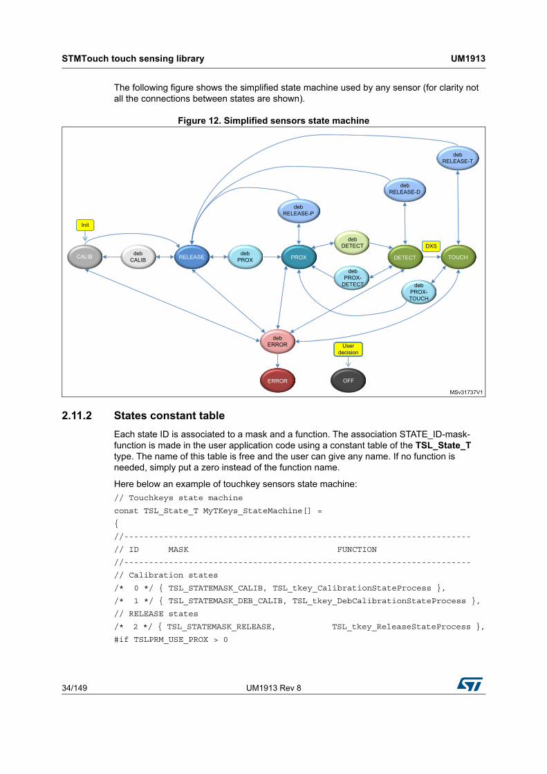
The following figure shows the simplified state machine used by any sensor (for clarity not all the connections between states are shown).
Figure 12. Simplified sensors state machine
2.11.2 States constant table
Each state ID is associated to a mask and a function. The association STATE_ID-mask-function is made in the user application code using a constant table of the TSL_State_T type. The name of this table is free and the user can give any name. If no function is needed, simply put a zero instead of the function name.
Here below an example of touchkey sensors state machine:
The STMTouch touch sensing library contains all the functions needed to manage each state. However the user can copy and adapt one or several functions to fit the application requirements.
Note: The two functions used to manage the ERROR and OFF states are not part of the STMTouch touch sensing library. These functions are managed by the application.
For linear and rotary sensor state machine, it is the same principle. The functions used to manage each state start with the prefix “TSL_linrot_”:
It consists in calculating the reference for all the channels of a sensor. An average of a certain number of measurements is done.
The number of measurement samples to use for the calibration is defined by the TSLPRM_CALIB_SAMPLES parameter.
After reset, the initialization method of each object is called. This method initializes the sensor parameters and then goes in the CALIBRATION state. After the calibration is done, the sensor goes in the RELEASE state or ERROR state if an error occurred.
Related functions:
• TSL_tkey_CalibrationStateProcess()
• TSL_linrot_CalibrationStateProcess()
• TSL_tkey_SetStateCalibration()
• TSL_linrot_SetStateCalibration()
Calibration delay
If a noise filter is used, it is necessary to wait a certain amount of measurement samples before to start the reference calculation. This number of samples to wait is defined by the TSLPRM_CALIB_DELAY parameter.
Re-calibration
If the calibration threshold is reached while in RELEASE state, a new calibration is performed. This re-calibration prevents the application to get stuck if something touches permanently the sensor, like a drop of water for example or if the sensor is touched upon power-on.
2.11.5 RELEASE state
Corresponds to the idle state of the sensor when no presence is detected.
Related functions:
• TSL_tkey_ReleaseStateProcess()
• TSL_linrot_ReleaseStateProcess()
2.11.6 PROXIMITY state
This state is optional and is enabled or disabled using the TSLPRM_USE_PROX parameter.
Related functions:
• TSL_tkey_ProxStateProcess()
• TSL_linrot_ProxStateProcess()
STMTouch touch sensing library UM1913
40/149 UM1913 Rev 8
2.11.7 DETECT state
It is the “normal” state when the sensor is touched.
Related functions:
• TSL_tkey_DetectStateProcess()
• TSL_linrot_DetectStateProcess()
2.11.8 TOUCH state
Same as DETECT state, except that this state is entered only by the DXS processing. If the DXS is not used, this state is never entered.
Related functions:
• TSL_tkey_TouchStateProcess()
• TSL_linrot_TouchStateProcess()
2.11.9 ERROR state
It is used to catch all acquisition errors detected in the other states. The management of this state must be performed at application level.
2.11.10 OFF state
It is used to inform the acquisition module to stop the burst and/or acquisition on the sensor channels. The management of this state must be performed at application level.
2.11.11 DEBOUNCE state
The debounce is optional and is enabled/disabled using the different debounce counters parameters: TSLPRM_DEBOUNCE_PROX, TSLPRM_DEBOUNCE_DETECT, TSLPRM_DEBOUNCE_RELEASE, TSLPRM_DEBOUNCE_CALIB, TSLPRM_DEBOUNCE_ERROR
The debounce is off if the corresponding parameter is equal to zero.
2.11.12 Reading the current state
The current state can be obtained by using the following functions:
• For touchkey sensor:
– TSL_tkey_GetStateId()
– TSL_tkey_GetStateMask()
• For linear and rotary sensor:
– TSL_linrot_GetStateId()
– TSL_linrot_GetStateMask()
The functions TSL_tkey_IsChanged() or TSL_linrot_IsChanged() allows the check if a sensor state has changed.
You can also directly read the state inside the sensor data structure:
if MyTKeys[0].p_Data->StateId == TSL_STATEID_DETECT)
UM1913 Rev 8 41/149
UM1913 STMTouch touch sensing library
148
2.11.13 Enabling a specific state
It is possible to enter directly in the CALIBRATION, OFF and OFF-with-burst-only” states. The OFF-with-burst-only state consists in only bursting the electrode without performing acquisition on it. It can be used in specific cases to improve the robustness against noise or to keep optimum sensor sensitivity.
This is done by using the following functions:
• For touchkey sensor:
– TSL_tkey_SetStateCalibration()
– TSL_tkey_SetStateOff()
– TSL_tkey_SetStateBurstOnly()
• For linear and rotary sensor:
– TSL_linrot_SetStateCalibration()
– TSL_linrot_SetStateOff()
– TSL_linrot_SetStateBurstOnly()
2.12 Environment change system (ECS)
2.12.1 Principle
Power supply voltage, temperature and air humidity may induce a slow variation of the measured signal. The environment change system (ECS) is used to adapt the reference to these environment changes.
The ECS processing is based on an infinite response digital low-pass filter of the first order (IIR filter):
with:
• Y = reference
• X = acquisition value (last measurement)
• K = coefficient.
The higher value for K, the faster the response time is. Two default K coefficients are available to obtain fast and slow responses.
The sampling frequency is programmable using a timing utility routine (see example below).
If the sensor is in PROX, DETECT or TOUCH states, the ECS is disabled for the duration of the detection timeout or for the duration of the touch (whichever ends first).
When the ECS is disabled, Yn = Yn - 1.
As soon as the recalibration times out or the detection ends, the filter is set active again.
Y n( ) K X× n( ) 1 K–( ) Y n 1–( )×+=
STMTouch touch sensing library UM1913
42/149 UM1913 Rev 8
The figure below shows the K filter effect to staircase on reference.The horizontal axis represents the number of calls to ECS_process() API. So the response time depends on the ECS_DELAY.
Figure 13. Reference versus K filter value
2.12.2 Resources
The ECS functions are provided in the files:
• tsl_ecs.c
• tsl_ecs.h
The functions are:
• TSL_ecs_Process(): main function to be used by the user
• TSL_ecs_CalcK(): additional function
• TSL_ecs_ProcessK(): additional function
2.12.3 Parameters
• TSLPRM_ECS_K_FAST
• TSLPRM_ECS_K_SLOW
• TSLPRM_ECS_DELAY
2.12.4 Use example
The ECS processing is usually performed in the main state machine at regular time intervals defined by the user. But it can also be done in interrupt routines. It must be performed after the sensors state machine is processed.
UM1913 Rev 8 43/149
UM1913 STMTouch touch sensing library
148
The ECS is activated only when all the sensors are in RELEASE, ERROR or OFF states, with at least one sensor in RELEASE state. It can also be delayed from milli-seconds to few seconds.
The ECS processing is performed on a group of sensors defined by the user. Different groups can be created and ECS can be applied on these groups with different K coefficients. The user decides the best thing to do for his application.
The simplest way is to call the TSL_ecs_Process() function in the main application loop, using the default K coefficients defined in the configuration file: TSL_ecs_Process(&MyObjGroup).
To call this function at regular time intervals, you can use the provide timing routine TSL_ecs_Process().
Example with ECS executed every 100 ms:
TSL_tTick_ms_T time_ECS_tick;
int main(void) {
while (1) {
...
// ECS every 100 ms
if (TSL_tim_CheckDelay_ms(100, &time_ECS_tick) == TSL_STATUS_OK)
{
TSL_ecs_Process(&MyObjGroup);
}
...
}
}
The TSL_ecs_Process()function allows the use of a K coefficient different than the default value:
if (TSL_tim_CheckDelay_ms(100, &time_ECS_tick) == TSL_STATUS_OK)
{
if ((MyObjGroup->StateMask & TSL_STATE_RELEASE_BIT_MASK) &&
!(MyObjGroup->StateMask & TSL_STATEMASK_ACTIVE))
{
TSL_ecs_ProcessK(&MyObjGroup, 120);
}
}
To update TSL_ecs_Process(), the system tick handler must be updated as follows:
void SysTick_Handler(void)
{
/* USER CODE BEGIN SysTick_IRQn 0 */
/* USER CODE END SysTick_IRQn 0 */
HAL_IncTick();
HAL_SYSTICK_IRQHandler();
/* USER CODE BEGIN SysTick_IRQn 1 */
STMTouch touch sensing library UM1913
44/149 UM1913 Rev 8
// TSL timing for ECS, DTO, ...
TSL_tim_ProcessIT();
/* USER CODE END SysTick_IRQn 1 */
}
2.13 Detection exclusion system (DXS)
2.13.1 Principle
The DXS processing is used to prevent several sensors to be in the DETECT state at the same time. This may happen if the sensors are closed to each other or if their sensitivity is too high. This can be useful also in some applications to prevent the user to touch at the same time several sensors with “opposite” meaning (volume up and volume down for example).
The first sensor in the group of sensors has the priority and enters in the DETECT state (with the DxSLock flag set). The other sensors are “blocked” and enter instead in the TOUCH state.
Note: A particular care must be taken when designing sensors that are shared between multiple DXS groups. The sensor that is assigned in the DETECT state depends on the sensors position in the DXS groups and also on the order of the DXS groups processing. See the examples 1 and 2 below for more detail.
The figure below illustrates the difference in behavior for a group of three sensors (touchkeys), part of the same DXS group, when the DXS is off and on (touchkeys can be replaced by linear or rotary sensors).
Figure 14. DXS principle
TOUCH
DETECT
TOUCH
MSv31738V3
RELEASE DETECTDETECT
DETECTDETECT
RELEASE DETECTTOUCH
DETECTTOUCH
DXS OFF
DXS ONsame group
RELEASEDETECTTKey1 RELEASE RELEASE DETECT RELEASE
DETECTRELEASE RELEASEDETECTTKey2
TKey3 RELEASE DETECT
RELEASEDETECTTKey1 RELEASE RELEASE RELEASE
RELEASE RELEASEDETECTTKey2
TKey3 RELEASE
RELEASE
time
RELEASE
timeTKey3 takes the priority
TKey1 is also “blocked”TKey3 is “blocked”TKey2 takes
the priorityTKey1 has the priority
TKey2 is “blocked”
TKey1 and TKey2 are released
All TKeys are touched
TKey2 and TKey3are touched together
TKey1 is released
TKey1 and TKey2are touched together
UM1913 Rev 8 45/149
UM1913 STMTouch touch sensing library
148
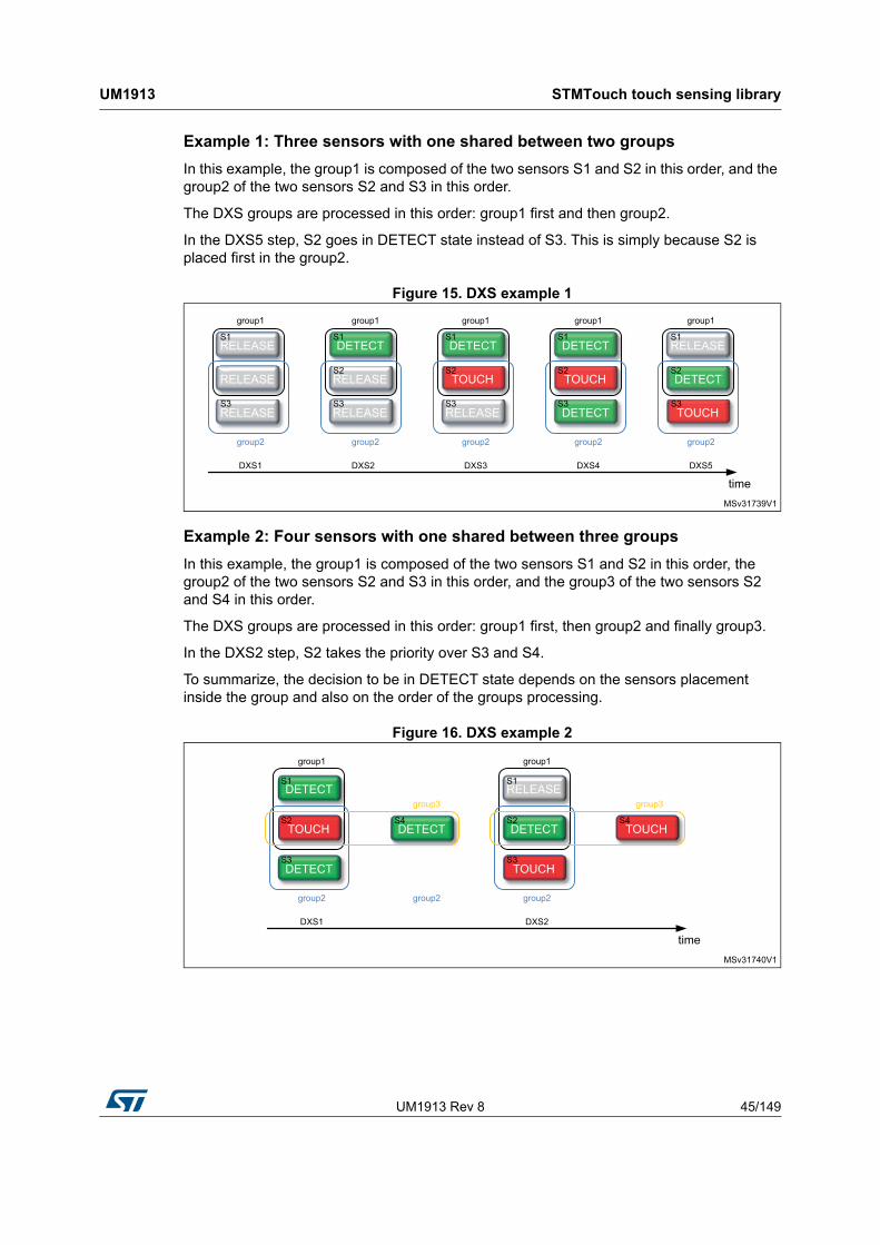
Example 1: Three sensors with one shared between two groups
In this example, the group1 is composed of the two sensors S1 and S2 in this order, and the group2 of the two sensors S2 and S3 in this order.
The DXS groups are processed in this order: group1 first and then group2.
In the DXS5 step, S2 goes in DETECT state instead of S3. This is simply because S2 is placed first in the group2.
Figure 15. DXS example 1
Example 2: Four sensors with one shared between three groups
In this example, the group1 is composed of the two sensors S1 and S2 in this order, the group2 of the two sensors S2 and S3 in this order, and the group3 of the two sensors S2 and S4 in this order.
The DXS groups are processed in this order: group1 first, then group2 and finally group3.
In the DXS2 step, S2 takes the priority over S3 and S4.
To summarize, the decision to be in DETECT state depends on the sensors placement inside the group and also on the order of the groups processing.
Figure 16. DXS example 2
DETECTRELEASE RELEASE TOUCH
DETECTTOUCHTOUCHRELEASE
DETECT
MSv31739V1
DETECTRELEASE DETECT RELEASE
timeDXS5DXS4DXS3DXS2DXS1
S1 S1 S1S1 S1
S2 S2 S2S2 S2
S3RELEASES3 S3S3 S3
SSSS2S2S2S2SS2RELEASE
group2 group2 group2 group2 group2
group1 group1 group1 group1 group1
TOUCH
TOUCH
DETECTDETECT
DETECT
TOUCH
DETECTS1
S2
S3
group2
group1
RELEASE
MSv31740V1
timeDXS2DXS1
S1
S4 S2
S3
group2 group2
group3
group1
S4
group3
STMTouch touch sensing library UM1913
46/149 UM1913 Rev 8
2.13.2 Resources
The DXS functions are provided in the files:
• tsl_dxs.c
• tsl_dxs.h
The function to use is TSL_dxs_FirstObj().
2.13.3 Parameter
• TSLPRM_USE_DXS
2.13.4 Use example
The DXS processing is performed usually in the main state machine but it can also be done in interrupt routines.
Warning: The DXS must be absolutely performed after the sensors state machine is processed, that is after the call to the TSL_obj_GroupProcess() function (see the main state machine for more details).
The DXS processing is performed on a group of sensors defined by the user. Different groups of DXS can be created.
It is up to the user to decide the best partitioning for the application.
Example:
int main(void) {
while (1) {
...
TSL_obj_GroupProcess(&MyObjGroup1);
TSL_obj_GroupProcess(&MyObjGroup2);
TSL_dxs_FirstObj(&MyObjGroup1);
TSL_dxs_FirstObj(&MyObjGroup2);
...
}
}
2.14 Detection time out (DTO)
2.14.1 Principle
The detection time out (DTO) introduces a simple way to cope with water film and any obstacle that may come in contact with a sensor. It introduces a maximum duration for the DETECTED state of any sensor called the DTO.
UM1913 Rev 8 47/149
UM1913 STMTouch touch sensing library
148
After this period of time, the sensor is automatically re-calibrated. This allows the sensor to be made touch sensitive again, even if the obstacle or the liquid film is still present on the application front panel.
This feature is application dependent and the time out must be tuned according to the user interface specifications.
The DTO is applied on the PROX, DETECT and TOUCH states and can be disabled.
2.14.2 Resources
The DTO functions are provided in the files:
• tsl_touchkey.c
• tsl_touchkey.h
• tsl_linrot.c
• tsl_linrot.h
The functions used by the DTO are:
• TSL_tkey_DTOGetTime()
• TSL_linrot_DTOGetTime()
• TSL_tim_CheckDelay_sec()
Note: The user does not need to call these functions to perform the DTO.
2.14.3 Parameter
• TSLPRM_DTO
2.14.4 Use example
The DTO is automatically performed inside the sensor state machine. The user does not need to call any function in the application code.
The DTO is disabled by writing zero in the TSLPRM_DTO parameter.
2.15 Noise filters
2.15.1 Principle
The STMTouch touch sensing library has been designed to facilitate the implementation of different noise filters. These filters can be used for many purpose and can range from very simple design to very complicated.
2.15.2 Resources
The filters are defined in the files:
• tsl_filter.c
• tsl_filter.h
Each filter is described by a function:
• TSL_filt_MeasFilter(): filter on measurement values
• TSL_filt_DeltaFilter(): filter on delta values
STMTouch touch sensing library UM1913
48/149 UM1913 Rev 8
2.15.3 Parameter
There is no parameter for the filter module.
2.15.4 Use example
The filter functions can be called at anytime in the main application. In order to speed up the execution time and to gain RAM space, the measure and delta filters are called by the TSL_acq_BankGetResult() function.
Examples:
// Apply a filter on the measures only
TSL_acq_BankGetResult(0, TSL_filt_MeasFilter, 0);
// Get the measures without applying any filter
TSL_acq_BankGetResult(0, 0, 0);
Note: The user can also create his own filter functions.
2.16 Timing management
2.16.1 Principle
The STMTouch touch sensing library needs an internal clock (“timing”), in particular for the ECS and DTO processing.
The timing process consists to increment a global variable at a regular interval. Different functions are then used to compare the current “time” and to check if a certain delay has elapsed.
The SysTick is used as timebase for the STMTouch touch sensing library. Its initialization must be done in the user code layer. Usually it is already done by the HAL_Init function. The TSLPRM_TICK_FREQ parameter must be set accordingly.
2.16.2 Resources
The common timing routines are described in the files:
• tsl_time.c
• tsl_time.h
Functions are:
• TSL_tim_ProcessIT()
• TSL_tim_CheckDelay_ms()
• TSL_tim_CheckDelay_sec()
2.16.3 Parameter
• TSLPRM_TICK_FREQ: the value must be in line with the SysTick frequency that is initialized in the user code.
UM1913 Rev 8 49/149
UM1913 STMTouch touch sensing library
148
2.16.4 Use example
The TSL_tim_CheckDelay_ms() function can be used in the main application code to execute some code (for example the ECS) at a regular interval.
Example:
TSL_tTick_ms_T time_ECS_tick;
TSL_tTick_ms_T time_LED_tick;
int main(void) {
TSL_Init(MyBanks); // The timing starts...
while (1) {
...
// Launch the ECS every 100 ms
if (TSL_tim_CheckDelay_ms(100, &time_ECS_tick) == TSL_STATUS_OK)
{
TSL_ecs_Process(&MyObjGroup);
}
// Toggle LED every 500 ms
if (TSL_tim_CheckDelay_ms(500, &time_LED_tick) == TSL_STATUS_OK)
{
ToggleLED();
}
...
}
}
2.17 Parameters
All the parameters are described in the tsl_conf.h file.
Note: The tsl_conf_<XXX>_template.h file present in the STM32_TouchSensing_Library/inc folder must be copied in the application project inc/tsl_conf.h and adapted to your application (number of channels, banks, debounce, DTO, etc.).
The structure TSL_Params_T is used to hold certain parameters that are common to all sensors. These parameters can be changed by the user while the application is running.
Parameters checking
All common parameters are verified (presence and value range) in the tsl_check_config.h file.
All device specific parameters are verified in the tsl_check_config_<XXX>.h file.
STMTouch touch sensing library UM1913
50/149 UM1913 Rev 8
2.18 Sensors acquisition timings
Reminders regarding terminology used in this section are given below:
• Bank: set of channels acquired simultaneously belonging to different groups
• Channel: elementary acquisition item (a GPIO from a group connected to a sensor)
• Group (also known as TSC group): set of up to four GPIOs defined as one sampling capacitor (Cs) with up to three channels or an active shield
• Shield: set of track and hatched plane used to increase noise robustness
• Active shield: a channel connected to an hatched plane driven simultaneously to sensor channels belonging to the same bank. An active shield requires its own sampling capacitor.
• Passive shield: a plane preferably hatched connected to the ground
This section details sequences for system with the following configurations:
• Touchkey sensor only
• Linear or rotary sensor only
• Mixed configuration using touchkey, and/or linear and/or rotary sensors
2.18.1 Acquisition timing using touchkey sensors
The examples detailed in the tables below summarize dependencies between Group, Bank, sensor number and acquisition timing, for STM32F0, STM32L4 and STM32WB Series.
For example:
• Three sensors can be acquired in:
– 1 time using 3 groups and 1 bank
– 2 times using 2 groups and 2 banks
– 3 times using 1 groups and 3 banks
• Five sensors can be acquired in:
– 1 time using 5 groups and 1 bank
– 2 times using 3 groups and 2 banks
– 3 times using 2 groups and 3 banks
• Six sensors can be acquired in:
– 1 time using 6 groups and 1 bank
– 2 times using 3 groups and 2 banks
– 3 times using 2 groups and 3 banks
Using up to three touchkey sensors on the same group
As a group is able to handle up to three channels, this use case can be handled using only one group. An extra group can also be added for the shield.
The main advantages of this configuration are the following:
• reduced number of used GPIOs
• only one sampling capacitor required for three touchkeys
Table 7 gives an example based on G1 and G2 and Table 8 details the corresponding acquisition time line.
UM1913 Rev 8 51/149
UM1913 STMTouch touch sensing library
148
the table below provides a synthesis list of features for this example. This is the most simple use case. In this case sensor acquisition is sequential.
Table 7. Example based on G1/G2 (3 touchkey sensors)
Group I/O Channel(1) Sampling Touchkey Bank
G1
IO1 - CS = 22 nF - -
IO2 CH1 - K1 B1
IO3 CH2 - K2 B2
IO4 CH3 - K3 B3
G2
IO1 - CS = 47 nF - -
IO2 SHIELD - - -
IO3 - - - -
IO4 - - - -
1. Green is used for CHx and blue for SHIELD.
Table 8. Example G1/G2 (3 touchkey sensors) - Acquisition time line
Time T0 T1 T2 T3 T4 T5 T6 T7 T8
B1/B2/B3↑(1) eoa(2) ↑ eoa ↑ eoa
P1(3) I(4) P2 I P3 I P1 I P2 I P3 I P1 I P2 I P3 IK1/CH1 Γ(5) Γ Γ
K2/CH2 Γ Γ Γ
K3/CH3 Γ Γ Γ
SHIELD Γ Γ Γ Γ Γ Γ Γ Γ Γ
1. ↑ = start of bank Bx acquisition.
2. eoa = end of Bx acquisition.
3. Px = program groups and channels for Bank x.
4. I = interrupt.
5. Γ = charge transfer cycle (green for CHx and blue for SHIELD).
Table 9. Example G1/G2 (3 touchkey sensors) - Synthesis
Features Value
Sampling capacitance 1 + 1 (shield)
Pins without shield 4
Pins with shield 6
Cost Low
Response time 3 * T0
STMTouch touch sensing library UM1913
52/149 UM1913 Rev 8
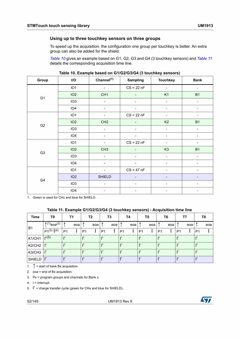
Using up to three touchkey sensors on three groups
To speed up the acquisition, the configuration one group per touchkey is better. An extra group can also be added for the shield.
Table 10 gives an example based on G1, G2, G3 and G4 (3 touchkey sensors) and Table 11 details the corresponding acquisition time line.
Table 10. Example based on G1/G2/G3/G4 (3 touchkey sensors)
Group I/O Channel(1) Sampling Touchkey Bank
G1
IO1 - CS = 22 nF - -
IO2 CH1 - K1 B1
IO3 - - - -
IO4 - - - -
G2
IO1 - CS = 22 nF - -
IO2 CH2 - K2 B1
IO3 - - - -
IO4 - - - -
G3
IO1 - CS = 22 nF - -
IO2 CH3 - K3 B1
IO3 - - - -
IO4 - - - -
G4
IO1 - CS = 47 nF - -
IO2 SHIELD - - -
IO3 - - - -
IO4 - - - -
1. Green is used for CHx and blue for SHIELD.
Table 11. Example G1/G2/G3/G4 (3 touchkey sensors) - Acquisition time line
P1(3) I(4) P1 I P1 I P1 I P1 I P1 I P1 I P1 I P1 IK1/CH1 Γ(5) Γ Γ Γ Γ Γ Γ Γ Γ
K2/CH2 Γ Γ Γ Γ Γ Γ Γ Γ Γ
K3/CH3 Γ Γ Γ Γ Γ Γ Γ Γ Γ
SHIELD Γ Γ Γ Γ Γ Γ Γ Γ Γ
1. ↑ = start of bank Bx acquisition.
2. eoa = end of Bx acquisition.
3. Px = program groups and channels for Bank x.
4. I = interrupt.
5. Γ = charge transfer cycle (green for CHx and blue for SHIELD).
UM1913 Rev 8 53/149
UM1913 STMTouch touch sensing library
148
The table below provides a synthesis list of features for this example. This is the way to acquire all sensors at the same time.
Note: The Groups pin not used for channel handling (such as IO3/4 in the example above) must not be used for analog features.
Using more than three touchkey sensors
To handle more than three touchkey sensors, more than one group is needed as the maximum number of channels per group is three. An extra group can also be used for the shield.
Table 13 gives an example based on G1, G2, G3 and G4 with 9 touchkey sensors and Table 14 details the corresponding acquisition time line.
Table 12. Example G1/G2/G3/G4 (3 touchkey sensors) - Synthesis
Feature Value
Sampling capacitance 3+ 1 (shield)
Pins without shield 6
Pins with shield 8
Cost Medium
Response time 1 * T0
Table 13. Example based on G1/G2/G3/G4 (9 touchkey sensors)
Group I/O Channel(1) Sampling Key Bank
G1
IO1 - CS = 22 nF - -
IO2 CH1 - K1 B1
IO3 CH2 - K2 B2
IO4 CH3 - K3 B3
G2
IO1 - CS = 22 nF - -
IO2 CH4 - K4 B1
IO3 CH5 - K5 B2
IO4 CH6 - K6 B3
G3
IO1 - CS = 22 nF - -
IO2 CH7 - K7 B1
IO3 CH8 - K8 B2
IO4 CH9 - K9 B3
G4
IO1 - CS = 47 nF - -
IO2 SHIELD - - -
IO3 - - - -
IO4 - - - -
1. Green is used for CHx and blue for SHIELD.
STMTouch touch sensing library UM1913
54/149 UM1913 Rev 8
The table below provides a synthesis list of features for this example. This is the most complex use case.
Table 14. Example G1/G2/G3/G4 (9 touchkey sensors) - Acquisition time line
Time T0 T1 T2 T3 T4 T5 T6 T7 T8
B1/B2/B3↑(1) eoa(2) ↑ eoa ↑ eoa
P1(3) I(4) P2 I P3 I P1 I P2 I P3 I P1 I P2 I P3 IK1/CH1 Γ(5) Γ Γ
K2/CH2 Γ Γ Γ
K3/CH3 Γ Γ Γ
K4/CH4 Γ Γ Γ
K5/CH5 Γ Γ Γ
K6/CH6 Γ Γ Γ
K7/CH7 Γ Γ Γ
K8/CH8 Γ Γ Γ
K9/CH9 Γ Γ Γ
SHIELD Γ Γ Γ Γ Γ Γ Γ Γ Γ
1. ↑ = start of bank Bx acquisition.
2. eoa = end of Bx acquisition.
3. Px = program groups and channels for Bank x.
4. I = interrupt.
5. Γ = charge transfer cycle (green for CHx and blue for SHIELD).
Table 15. Example G1/G2/G3/G4 (9 keys)- Synthesis
Feature Value
Sampling capacitance 3+ 1 (shield)
Pins without shield 12
Pins with shield 14
Cost Medium
Response time 3 * T0
UM1913 Rev 8 55/149
UM1913 STMTouch touch sensing library
148
Using only few specific touchkey sensors
If only some touchkey sensors must be acquired, the bank helps to start the acquisition only on these specific touchkeys.
The table below shows an example of the acquisition time line in this case.
2.18.2 Acquisition timing using linear or rotary sensors
To handle linear or rotary sensors in a proper way regarding sensitivity, it is recommended to split linear and rotary channels on various groups.
For example, three groups needed to handle three linear/rotary channels.
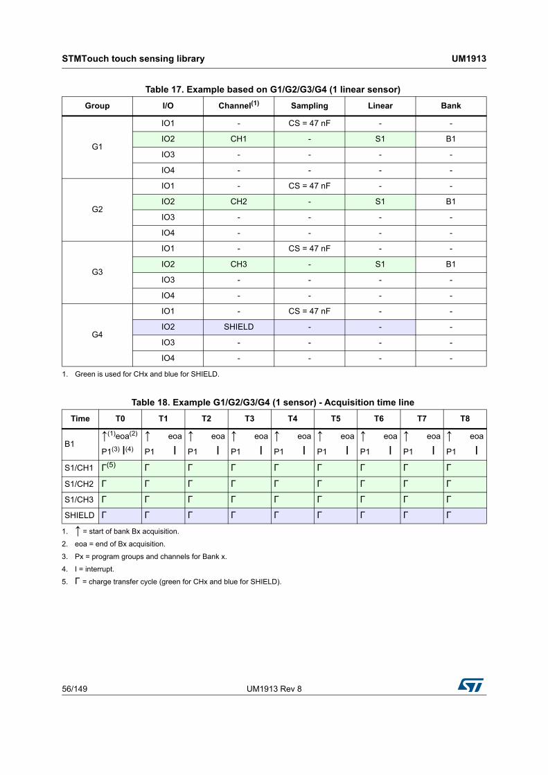
Using one linear/rotary sensor
Three groups are used to handle the three channels. An extra group can also be used for the shield.
Table 17 gives an example based on G1, G2, G3 and G4 (one linear sensor) and Table 18 details the corresponding acquisition time line.
Table 16. Example G1/G2/G3/G4 (specific touch key sensors only) - Acquisition time line
Time T0 T1 T2 T3 T4 T5 T6 T7 T8
B1/B2/B3↑(1)eoa(2) ↑ eoa ↑ eoa ↑ eoa ↑ eoa
P1(3) I(4) P1 I P1 I P2 I P3 I P1 I P2 I P3 IK1/CH1 Γ(5) Γ Γ Γ
K2/CH2 Γ Γ
K3/CH3 Γ Γ
K4/CH4 Γ Γ Γ Γ
K5/CH5 Γ Γ
K6/CH6 Γ Γ
K7/CH7 Γ Γ Γ Γ
K8/CH8 Γ Γ
K9/CH9 Γ Γ
SHIELD Γ Γ Γ Γ Γ Γ Γ Γ
1. ↑ = start of bank Bx acquisition.
2. eoa = end of Bx acquisition.
3. Px = program groups and channels for Bank x.
4. I = interrupt.
5. Γ = charge transfer cycle (green for CHx and blue for SHIELD).
STMTouch touch sensing library UM1913
56/149 UM1913 Rev 8
Table 17. Example based on G1/G2/G3/G4 (1 linear sensor)
Group I/O Channel(1) Sampling Linear Bank
G1
IO1 - CS = 47 nF - -
IO2 CH1 - S1 B1
IO3 - - - -
IO4 - - - -
G2
IO1 - CS = 47 nF - -
IO2 CH2 - S1 B1
IO3 - - - -
IO4 - - - -
G3
IO1 - CS = 47 nF - -
IO2 CH3 - S1 B1
IO3 - - - -
IO4 - - - -
G4
IO1 - CS = 47 nF - -
IO2 SHIELD - - -
IO3 - - - -
IO4 - - - -
1. Green is used for CHx and blue for SHIELD.
Table 18. Example G1/G2/G3/G4 (1 sensor) - Acquisition time line
P1(3) I(4) P1 I P1 I P1 I P1 I P1 I P1 I P1 I P1 IS1/CH1 Γ(5) Γ Γ Γ Γ Γ Γ Γ Γ
S1/CH2 Γ Γ Γ Γ Γ Γ Γ Γ Γ
S1/CH3 Γ Γ Γ Γ Γ Γ Γ Γ Γ
SHIELD Γ Γ Γ Γ Γ Γ Γ Γ Γ
1. ↑ = start of bank Bx acquisition.
2. eoa = end of Bx acquisition.
3. Px = program groups and channels for Bank x.
4. I = interrupt.
5. Γ = charge transfer cycle (green for CHx and blue for SHIELD).
UM1913 Rev 8 57/149
UM1913 STMTouch touch sensing library
148
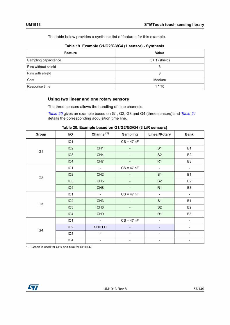
The table below provides a synthesis list of features for this example.
Using two linear and one rotary sensors
The three sensors allows the handling of nine channels.
Table 20 gives an example based on G1, G2, G3 and G4 (three sensors) and Table 21 details the corresponding acquisition time line.
Table 19. Example G1/G2/G3/G4 (1 sensor) - Synthesis
Feature Value
Sampling capacitance 3+ 1 (shield)
Pins without shield 6
Pins with shield 8
Cost Medium
Response time 1 * T0
Table 20. Example based on G1/G2/G3/G4 (3 L/R sensors)
Group I/O Channel(1) Sampling Linear/Rotary Bank
G1
IO1 - CS = 47 nF - -
IO2 CH1 - S1 B1
IO3 CH4 - S2 B2
IO4 CH7 - R1 B3
G2
IO1 - CS = 47 nF - -
IO2 CH2 - S1 B1
IO3 CH5 - S2 B2
IO4 CH8 - R1 B3
G3
IO1 - CS = 47 nF - -
IO2 CH3 - S1 B1
IO3 CH6 - S2 B2
IO4 CH9 - R1 B3
G4
IO1 - CS = 47 nF - -
IO2 SHIELD - - -
IO3 - - - -
IO4 - - - -
1. Green is used for CHx and blue for SHIELD.
STMTouch touch sensing library UM1913
58/149 UM1913 Rev 8
The table below provides a synthesis list of features for this example.
2.18.3 Acquisition timing using touchkey, linear and rotary sensors
Table 23 gives an example based on G1, G2, G3 and G4, with three touchkey, one linear and one rotary sensors and Table 24 details the corresponding acquisition time line.
Table 21. Example G1/G2/G3/G4 (3 L/R sensors) - Acquisition time line
Time T0 T1 T2 T3 T4 T5 T6 T7 T8
B1↑(1)eoa(2) ↑ eoa ↑ eoa
P1(3) I(4) P1 I P1 I
B2↑ eoa ↑ eoa ↑ eoa
P2 I P2 I P2 I
B3↑ eoa ↑ eoa ↑ eoa
P3 I P3 I P3 IS1/CH1 Γ(5) Γ Γ
S1/CH2 Γ Γ Γ
S1/CH3 Γ Γ Γ
S2/CH4 Γ Γ Γ
S2/CH5 Γ Γ Γ
S2/CH6 Γ Γ Γ
R1/CH7 Γ Γ Γ
R1/CH8 Γ Γ Γ
R1/CH9 Γ Γ Γ
SHIELD Γ Γ Γ Γ Γ Γ Γ Γ Γ
1. ↑ = start of bank Bx acquisition.
2. eoa = end of Bx acquisition.
3. Px = program groups and channels for Bank x.
4. I = interrupt.
5. Γ = charge transfer cycle (green for CHx and blue for SHIELD).
Table 22. Example G1/G2/G3/G4 (3 L/R sensors) - Synthesis
Feature Value
Sampling capacitance 3+ 1 (shield)
Pins without shield 12
Pins with shield 14
Cost Medium
Response time 3 * T0
UM1913 Rev 8 59/149
UM1913 STMTouch touch sensing library
148
Table 23. Example based on G1, G2, G3 and G4 (3 touchkey, 1 linear, 1 rotary sensors)
Group I/O Channel(1) Sampling Touchkey Linear/Rotary Bank
G1
IO1 - CS = 47 nF - - -
IO2 CH1 - - S1 B1
IO3 CH4 - K1 - B2
IO4 CH7 - - R1 B3
G2
IO1 - CS = 47 nF - - -
IO2 CH2 - - S1 B1
IO3 CH5 - K2 - B2
IO4 CH8 - - R1 B3
G3
IO1 - CS = 47 nF - - -
IO2 CH3 - - S1 B1
IO3 CH6 - K3 - B2
IO4 CH9 - - R1 B3
G4
IO1 - CS = 47 nF - - -
IO2 SHIELD - - - -
IO3 - - - - -
IO4 - - - - -
1. Green is used for CHx and blue for SHIELD.
STMTouch touch sensing library UM1913
60/149 UM1913 Rev 8
The table below provides a synthesis list of features for this example.
Table 24. Example G1/G2/G3/G4 (3 touchkey, 1 linear, 1 rotary sensors) - Acquisition time line
Time T0 T1 T2 T3 T4 T5 T6 T7 T8
B1↑(1)eoa(2) ↑ eoa ↑ eoa
P1(3) I(4) P1 I P1 I
B2↑ eoa ↑ eoa ↑ eoa
P2 I P2 I P2 I
B3↑ eoa ↑ eoa ↑ eoa
P3 I P3 I P3 IS1/CH1 Γ(5) Γ Γ
S1/CH2 Γ Γ Γ
S1CH3 Γ Γ Γ
K1/CH4 Γ Γ Γ
K2/CH5 Γ Γ Γ
K3/CH6 Γ Γ Γ
R1/CH7 Γ Γ Γ
R1/CH8 Γ Γ Γ
R1/CH9 Γ Γ Γ
SHIELD Γ Γ Γ Γ Γ Γ Γ Γ Γ
1. ↑ = start of bank Bx acquisition.
2. eoa = end of Bx acquisition.
3. Px = program groups and channels for Bank x.
4. I = interrupt.
5. Γ = charge transfer cycle (green for CHx and blue for SHIELD).
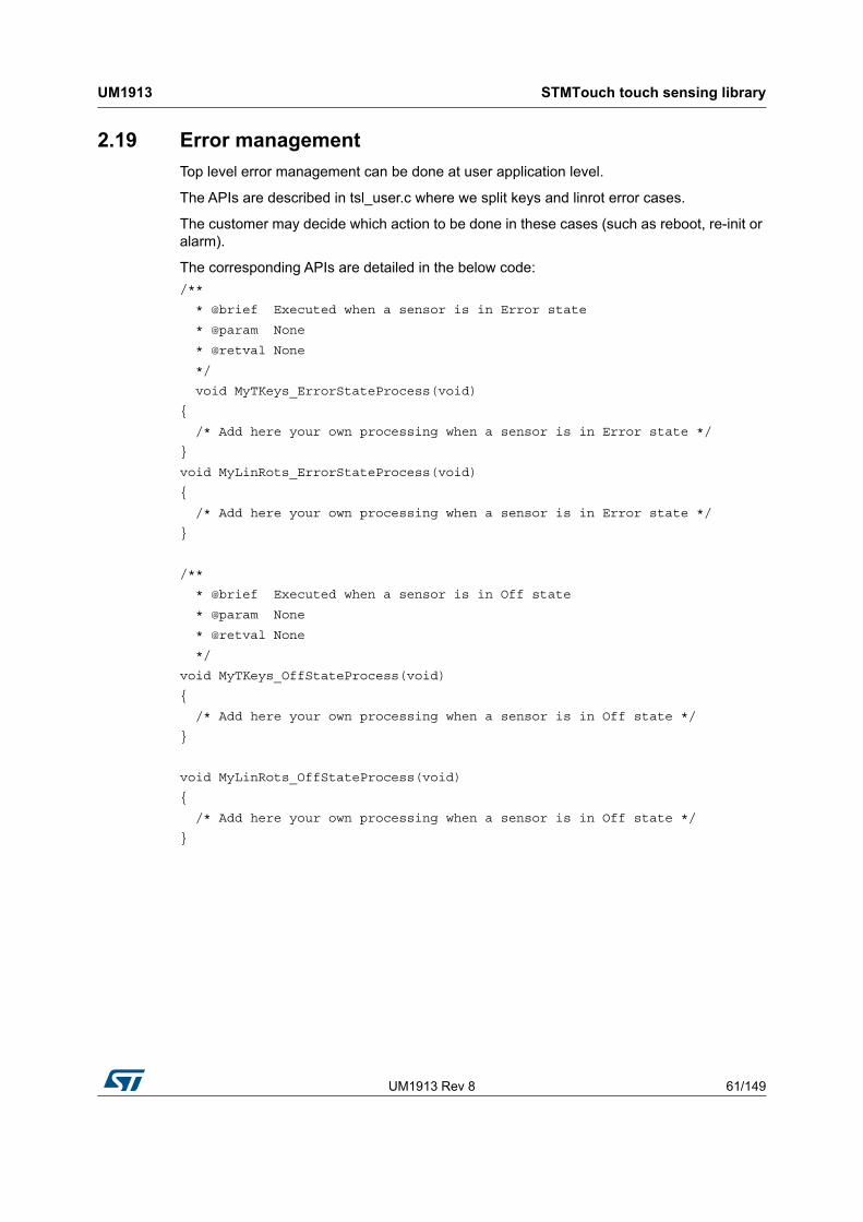
Top level error management can be done at user application level.
The APIs are described in tsl_user.c where we split keys and linrot error cases.
The customer may decide which action to be done in these cases (such as reboot, re-init or alarm).
The corresponding APIs are detailed in the below code:
/**
* @brief Executed when a sensor is in Error state
* @param None
* @retval None
*/
void MyTKeys_ErrorStateProcess(void)
{
/* Add here your own processing when a sensor is in Error state */
}
void MyLinRots_ErrorStateProcess(void)
{
/* Add here your own processing when a sensor is in Error state */
}
/**
* @brief Executed when a sensor is in Off state
* @param None
* @retval None
*/
void MyTKeys_OffStateProcess(void)
{
/* Add here your own processing when a sensor is in Off state */
}
void MyLinRots_OffStateProcess(void)
{
/* Add here your own processing when a sensor is in Off state */
}
Devices with TSC peripheral UM1913
62/149 UM1913 Rev 8
3 Devices with TSC peripheral
This section concerns all STM32 microcontrollers that include the touch sensing controller peripheral (TSC).
3.1 Acquisition
The acquisition is done in the files:
• tsl_acq_tsc.c
• tsl_acq_tsc.h
Functions used by the application layer and that are device dependent:
• TSL_acq_BankConfig()
• TSL_acq_BankStartAcq()
• TSL_acq_BankWaitEOC()
• TSL_acq_GetMeas()
The other functions in this file are for internal use and the user does not need to call them directly.
The device selection must be done at the end of the tsl_conf.h file:
#include "stm32f0xx.h" /* Select the file corresponding to the device in use (i.e. stm32f3xx.h, stm32f0xx.h, ...) */
3.2 Timings
The timing management is done in the files:
• tsl_time.c
• tsl_time.h
The SysTick is used to generate a timebase for the ECS and DTO modules. It must be initialized in the user code (already done by the HAL_init function).
3.3 Parameters
The parameters are described in the tsl_conf_tsc_template.h file (to be copied in the project and rename in tsl_conf.h).
Parameters are checked in the tsl_check_config_tsc.h file.
UM1913 Rev 8 63/149
UM1913 Devices with TSC peripheral
148
3.4 MCU resources
The table below shows the peripherals used by the STMTouch touch sensing library on any STM32 microcontroller with the touch sensing controller. Care must be taken when using them to avoid any unwanted behavior.
3.5 STM32F0 Series microcontrollers
3.5.1 Memory footprint
Conditions
• IAR ANSI C/C++ compiler/linker V7.40.3.8902 for Arm
• Each sensor has its own parameters placed in RAM.
The following table summarizes the memory footprint with different configurations.
Table 26. STM32F0 Series MCU resources used
Peripheral Function
GPIOs Acquisition
SysTick Time base for ECS and DTO
Touch sensing controller (TSC) Acquisition
Table 27. STM32F0 Series memory footprint(1)
1. The content of this table is provided for information purposes only.
Channels Banks Sensors ROM (Kbytes) RAM (bytes)
1 1 1 TKey 3.0 100
2 1 2 TKeys 3.0 120
2 2 2 TKeys 3.0 120
24 3 24 TKeys 4.0 620
3 1 1 Linear-3ch 4.1 130
15 3 12 TKeys + 1 Linear-3ch 6.2 420
24 3 18 TKeys + 2 Linear-3ch 6.5 610
Dev
ices
with
TS
C p
erip
he
ralU
M1
913
64/1
49U
M1
913 R
ev 8
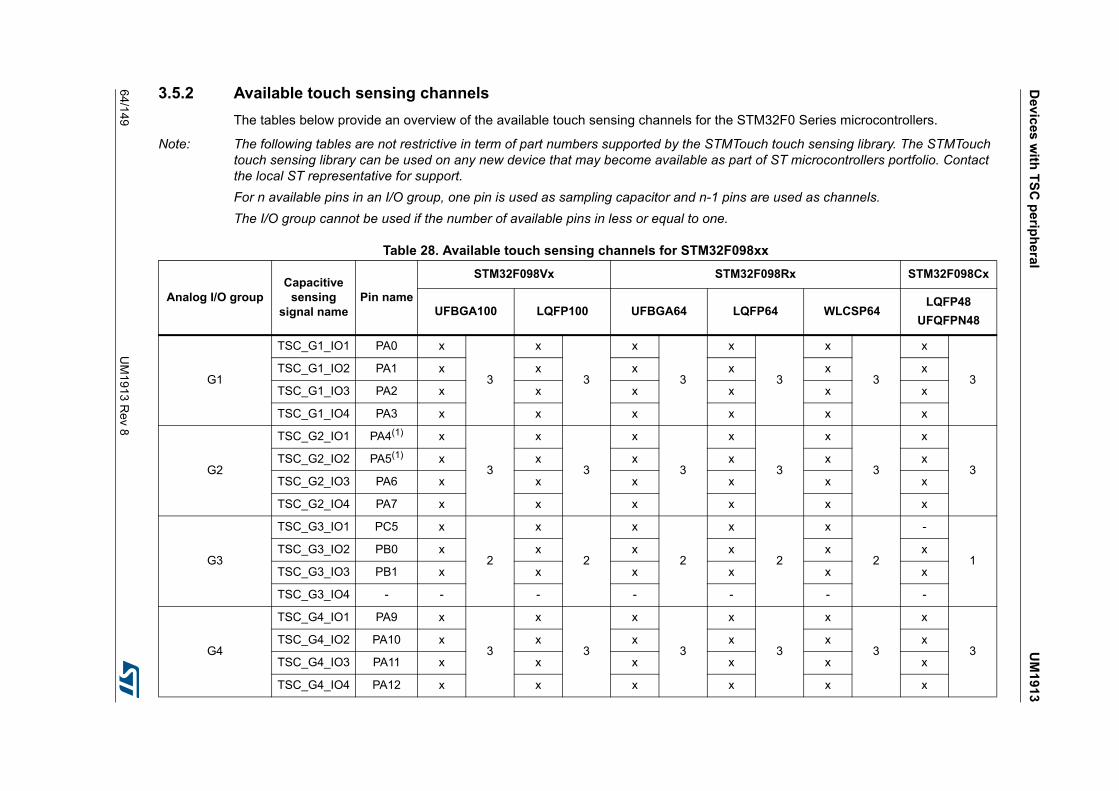
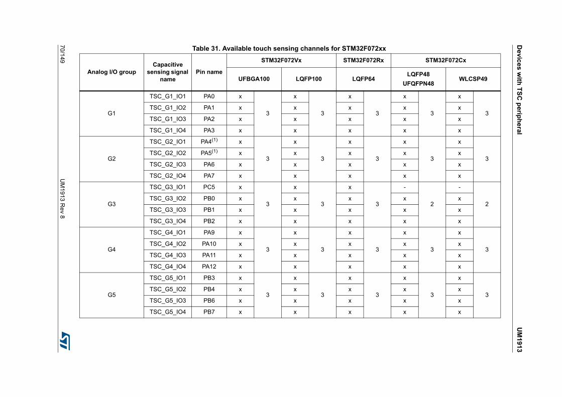
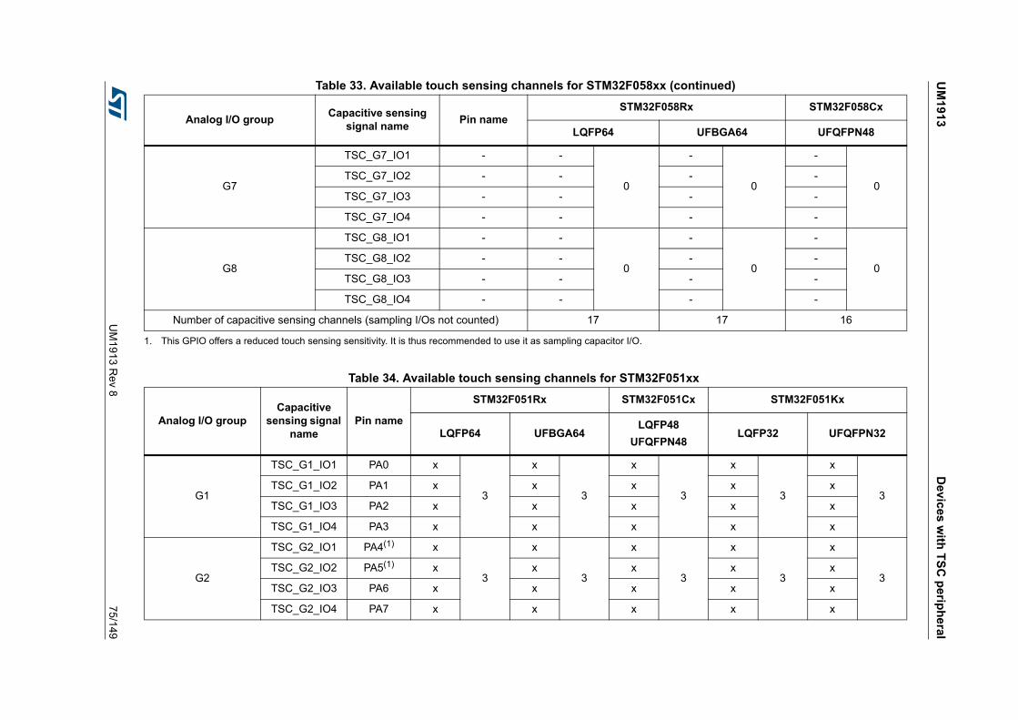
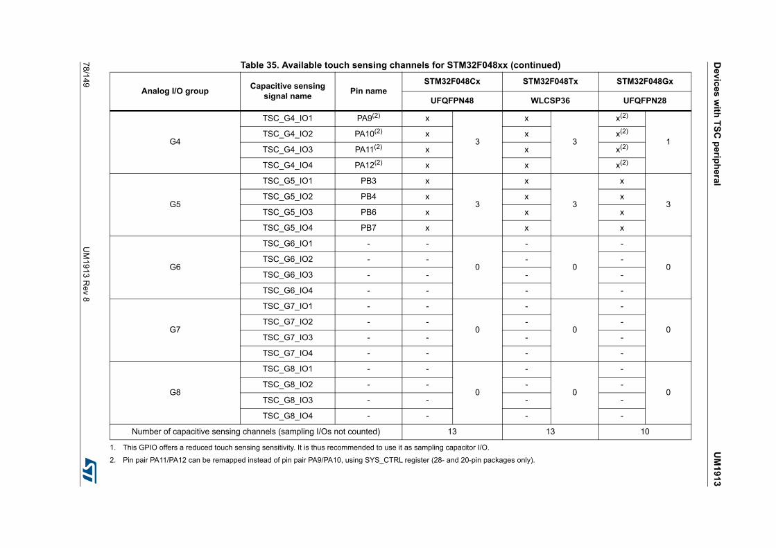
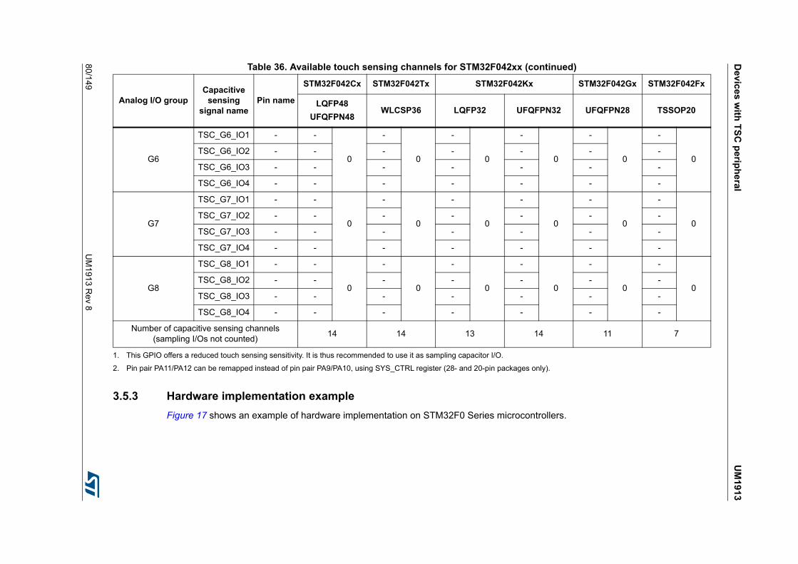
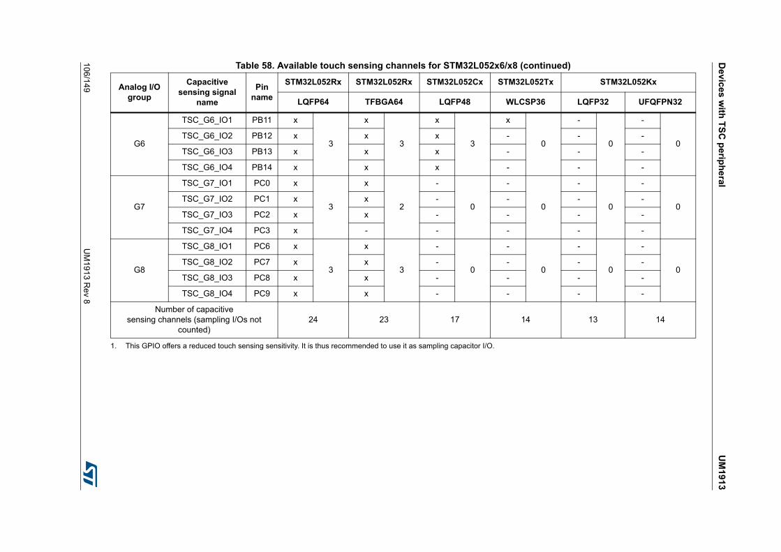
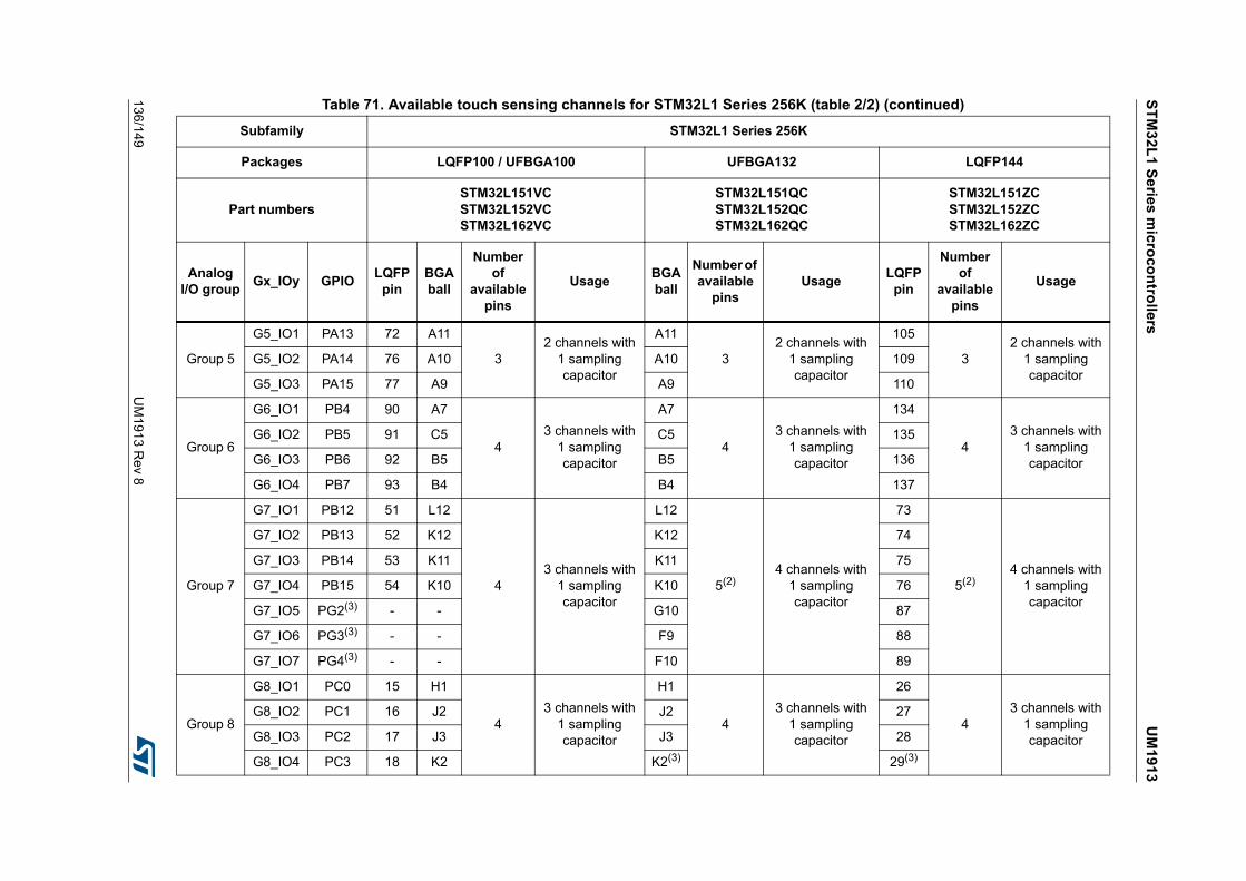
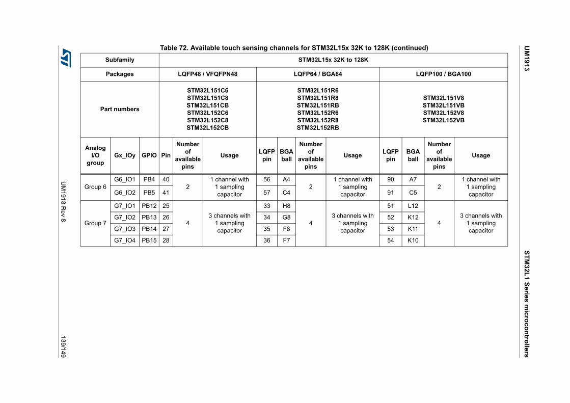
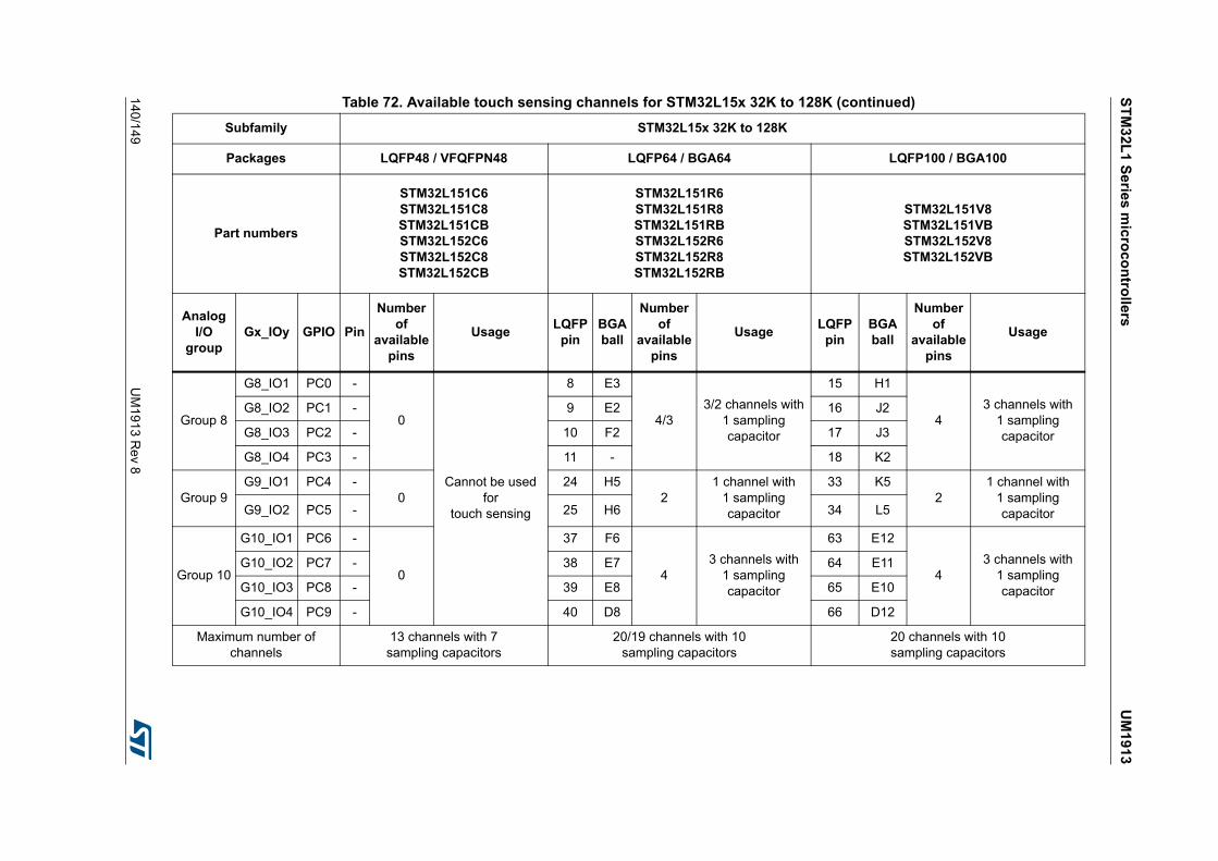
3.5.2 Available touch sensing channels
The tables below provide an overview of the available touch sensing channels for the STM32F0 Series microcontrollers.
Note: The following tables are not restrictive in term of part numbers supported by the STMTouch touch sensing library. The STMTouch touch sensing library can be used on any new device that may become available as part of ST microcontrollers portfolio. Contact the local ST representative for support.
For n available pins in an I/O group, one pin is used as sampling capacitor and n-1 pins are used as channels.
The I/O group cannot be used if the number of available pins in less or equal to one.
Table 28. Available touch sensing channels for STM32F098xx
Analog I/O groupCapacitive
sensing signal name
Pin name
STM32F098Vx STM32F098Rx STM32F098Cx
UFBGA100 LQFP100 UFBGA64 LQFP64 WLCSP64LQFP48
UFQFPN48
G1
TSC_G1_IO1 PA0 x
3
x
3
x
3
x
3
x
3
x
3TSC_G1_IO2 PA1 x x x x x x
TSC_G1_IO3 PA2 x x x x x x
TSC_G1_IO4 PA3 x x x x x x
G2
TSC_G2_IO1 PA4(1) x
3
x
3
x
3
x
3
x
3
x
3TSC_G2_IO2 PA5(1) x x x x x x
TSC_G2_IO3 PA6 x x x x x x
TSC_G2_IO4 PA7 x x x x x x
G3
TSC_G3_IO1 PC5 x
2
x
2
x
2
x
2
x
2
-
1TSC_G3_IO2 PB0 x x x x x x
TSC_G3_IO3 PB1 x x x x x x
TSC_G3_IO4 - - - - - - -
G4
TSC_G4_IO1 PA9 x
3
x
3
x
3
x
3
x
3
x
3TSC_G4_IO2 PA10 x x x x x x
TSC_G4_IO3 PA11 x x x x x x
TSC_G4_IO4 PA12 x x x x x x
UM
19
13D
evic
es w
ith T
SC
pe
riph
eral
UM
1913
Re
v 865/149
G5
TSC_G5_IO1 PB3 x
3
x
3
x
3
x
3
x
3
x
3TSC_G5_IO2 PB4 x x x x x x
TSC_G5_IO3 PB6 x x x x x x
TSC_G5_IO4 PB7 x x x x x x
G6
TSC_G6_IO1 PB11 x
3
x
3
x
3
x
3
x
3
x
3TSC_G6_IO2 PB12 x x x x x x
TSC_G6_IO3 PB13 x x x x x x
TSC_G6_IO4 PB14 x x x x x x
G7
TSC_G7_IO1 PE2 x
3
x
3
x
0
-
0
-
0
-
0TSC_G7_IO2 PE3 x x x - - -
TSC_G7_IO3 PE4 x x x - - -
TSC_G7_IO4 PE5 x x x - - -
G8
TSC_G8_IO1 PD12 x
3
x
3
x
0
-
0
-
0
-
0TSC_G8_IO2 PD13 x x x - - -
TSC_G8_IO3 PD14 x x x - - -
TSC_G8_IO4 PD15 x x x - - -
Number of capacitive sensing channels (sampling I/Os not counted)
23 23 17 17 17 16
1. This GPIO offers a reduced touch sensing sensitivity. It is thus recommended to use it as sampling capacitor I/O.
Table 28. Available touch sensing channels for STM32F098xx (continued)
Analog I/O groupCapacitive
sensing signal name
Pin name
STM32F098Vx STM32F098Rx STM32F098Cx
UFBGA100 LQFP100 UFBGA64 LQFP64 WLCSP64LQFP48
UFQFPN48
Dev
ices
with
TS
C p
erip
he
ralU
M1
913
66/1
49U
M1
913 R
ev 8
Table 29. Available touch sensing channels for STM32F091xx
Analog I/O groupCapacitive
sensing signal name
Pin name
STM32F091Vx STM32F091Rx STM32F091Cx
UFBGA100 LQFP100 UFBGA64 LQFP64 WLCSP64LQFP48
UFQFPN48
G1
TSC_G1_IO1 PA0 x
3
x
3
x
3
x
3
x
3
x
3TSC_G1_IO2 PA1 x x x x x x
TSC_G1_IO3 PA2 x x x x x x
TSC_G1_IO4 PA3 x x x x x x
G2
TSC_G2_IO1 PA4(1) x
3
x
3
x
3
x
3
x
3
x
3TSC_G2_IO2 PA5(1) x x x x x x
TSC_G2_IO3 PA6 x x x x x x
TSC_G2_IO4 PA7 x x x x x x
G3
TSC_G3_IO1 PC5 x
3
x
3
x
3
x
3
x
3
-
2TSC_G3_IO2 PB0 x x x x x x
TSC_G3_IO3 PB1 x x x x x x
TSC_G3_IO4 PB2 x x x x x x
G4
TSC_G4_IO1 PA9 x
3
x
3
x
3
x
3
x
3
x
3TSC_G4_IO2 PA10 x x x x x x
TSC_G4_IO3 PA11 x x x x x x
TSC_G4_IO4 PA12 x x x x x x
G5
TSC_G5_IO1 PB3 x
3
x
3
x
3
x
3
x
3
x
3TSC_G5_IO2 PB4 x x x x x x
TSC_G5_IO3 PB6 x x x x x x
TSC_G5_IO4 PB7 x x x x x x
UM
19
13D
evic
es w
ith T
SC
pe
riph
eral
UM
1913
Re
v 867/149
G6
TSC_G6_IO1 PB11 x
3
x
3
x
3
x
3
x
3
x
3TSC_G6_IO2 PB12 x x x x x x
TSC_G6_IO3 PB13 x x x x x x
TSC_G6_IO4 PB14 x x x x x x
G7
TSC_G7_IO1 PE2 x
3
x
3
x
0
-
0
-
0
-
0TSC_G7_IO2 PE3 x x x - - -
TSC_G7_IO3 PE4 x x x - - -
TSC_G7_IO4 PE5 x x x - - -
G8
TSC_G8_IO1 PD12 x
3
x
3
x
0
-
0
-
0
-
0TSC_G8_IO2 PD13 x x x - - -
TSC_G8_IO3 PD14 x x x - - -
TSC_G8_IO4 PD15 x x x - - -
Number of capacitive sensing channels(sampling I/Os not counted)
24 24 18 18 18 17
1. This GPIO offers a reduced touch sensing sensitivity. It is thus recommended to use it as sampling capacitor I/O.
Table 29. Available touch sensing channels for STM32F091xx (continued)
Analog I/O groupCapacitive
sensing signal name
Pin name
STM32F091Vx STM32F091Rx STM32F091Cx
UFBGA100 LQFP100 UFBGA64 LQFP64 WLCSP64LQFP48
UFQFPN48
Dev
ices
with
TS
C p
erip
he
ralU
M1
913
68/1
49U
M1
913 R
ev 8
Table 30. Available touch sensing channels for STM32F078xx
Analog I/O groupCapacitive
sensing signal name
Pin name
STM32F078Vx STM32F078Rx STM32F078Cx
UFBGA100 LQFP100 LQFP64LQFP48
UFQFPN48WLCSP49
G1
TSC_G1_IO1 PA0 x
3
x
3
x
3
x
3
x
3TSC_G1_IO2 PA1 x x x x x
TSC_G1_IO3 PA2 x x x x x
TSC_G1_IO4 PA3 x x x x x
G2
TSC_G2_IO1 PA4(1) x
3
x
3
x
3
x
3
x
3TSC_G2_IO2 PA5(1) x x x x x
TSC_G2_IO3 PA6 x x x x x
TSC_G2_IO4 PA7 x x x x x
G3
TSC_G3_IO1 PC5 x
2
x
2
x
2
-
1
-
1TSC_G3_IO2 PB0 x x x x x
TSC_G3_IO3 PB1 x x x x x
TSC_G3_IO4 - - - - - -
G4
TSC_G4_IO1 PA9 x
3
x
3
x
3
x
3
x
3TSC_G4_IO2 PA10 x x x x x
TSC_G4_IO3 PA11 x x x x x
TSC_G4_IO4 PA12 x x x x x
G5
TSC_G5_IO1 PB3 x
3
x
3
x
3
x
3
x
3TSC_G5_IO2 PB4 x x x x x
TSC_G5_IO3 PB6 x x x x x
TSC_G5_IO4 PB7 x x x x x
UM
19
13D
evic
es w
ith T
SC
pe
riph
eral
UM
1913
Re
v 869/149
G6
TSC_G6_IO1 PB11 x
3
x
3
x
3
x
3
x
3TSC_G6_IO2 PB12 x x x x x
TSC_G6_IO3 PB13 x x x x x
TSC_G6_IO4 PB14 x x x x x
G7
TSC_G7_IO1 PE2 x
3
x
3
-
0
-
0
-
0TSC_G7_IO2 PE3 x x - - -
TSC_G7_IO3 PE4 x x - - -
TSC_G7_IO4 PE5 x x - - -
G8
TSC_G8_IO1 PD12 x
3
x
3
-
0
-
0
-
0TSC_G8_IO2 PD13 x x - - -
TSC_G8_IO3 PD14 x x - - -
TSC_G8_IO4 PD15 x x - - -
Number of capacitive sensing channels(sampling I/Os not counted)
23 23 17 16 16
1. This GPIO offers a reduced touch sensing sensitivity. It is thus recommended to use it as sampling capacitor I/O.
Table 30. Available touch sensing channels for STM32F078xx (continued)
Analog I/O groupCapacitive
sensing signal name
Pin name
STM32F078Vx STM32F078Rx STM32F078Cx
UFBGA100 LQFP100 LQFP64LQFP48
UFQFPN48WLCSP49
Dev
ices
with
TS
C p
erip
he
ralU
M1
913
70/1
49U
M1
913 R
ev 8
Table 31. Available touch sensing channels for STM32F072xx
Analog I/O groupCapacitive
sensing signal name
Pin name
STM32F072Vx STM32F072Rx STM32F072Cx
UFBGA100 LQFP100 LQFP64LQFP48
UFQFPN48WLCSP49
G1
TSC_G1_IO1 PA0 x
3
x
3
x
3
x
3
x
3TSC_G1_IO2 PA1 x x x x x
TSC_G1_IO3 PA2 x x x x x
TSC_G1_IO4 PA3 x x x x x
G2
TSC_G2_IO1 PA4(1) x
3
x
3
x
3
x
3
x
3TSC_G2_IO2 PA5(1) x x x x x
TSC_G2_IO3 PA6 x x x x x
TSC_G2_IO4 PA7 x x x x x
G3
TSC_G3_IO1 PC5 x
3
x
3
x
3
-
2
-
2TSC_G3_IO2 PB0 x x x x x
TSC_G3_IO3 PB1 x x x x x
TSC_G3_IO4 PB2 x x x x x
G4
TSC_G4_IO1 PA9 x
3
x
3
x
3
x
3
x
3TSC_G4_IO2 PA10 x x x x x
TSC_G4_IO3 PA11 x x x x x
TSC_G4_IO4 PA12 x x x x x
G5
TSC_G5_IO1 PB3 x
3
x
3
x
3
x
3
x
3TSC_G5_IO2 PB4 x x x x x
TSC_G5_IO3 PB6 x x x x x
TSC_G5_IO4 PB7 x x x x x
UM
19
13D
evic
es w
ith T
SC
pe
riph
eral
UM
1913
Re
v 871/149
G6
TSC_G6_IO1 PB11 x
3
x
3
x
3
x
3
x
3TSC_G6_IO2 PB12 x x x x x
TSC_G6_IO3 PB13 x x x x x
TSC_G6_IO4 PB14 x x x x x
G7
TSC_G7_IO1 PE2 x
3
x
3
-
0
-
0
-
0TSC_G7_IO2 PE3 x x - - -
TSC_G7_IO3 PE4 x x - - -
TSC_G7_IO4 PE5 x x - - -
G8
TSC_G8_IO1 PD12 x
3
x
3
-
0
-
0
-
0TSC_G8_IO2 PD13 x x - - -
TSC_G8_IO3 PD14 x x - - -
TSC_G8_IO4 PD15 x x - - -
Number of capacitive sensing channels(sampling I/Os not counted)
24 24 18 17 17
1. This GPIO offers a reduced touch sensing sensitivity. It is thus recommended to use it as sampling capacitor I/O.
Table 31. Available touch sensing channels for STM32F072xx (continued)
Analog I/O groupCapacitive
sensing signal name
Pin name
STM32F072Vx STM32F072Rx STM32F072Cx
UFBGA100 LQFP100 LQFP64LQFP48
UFQFPN48WLCSP49
Dev
ices
with
TS
C p
erip
he
ralU
M1
913
72/1
49U
M1
913 R
ev 8
Table 32. Available touch sensing channels for STM32F071xx
Analog I/O groupCapacitive
sensing signal name
Pin name
STM32F071Vx STM32F071Rx STM32F071Cx
UFBGA100 LQFP100 LQFP64LQFP48
UFQFPN48WLCSP49
G1
TSC_G1_IO1 PA0 x
3
x
3
x
3
x
3
x
3TSC_G1_IO2 PA1 x x x x x
TSC_G1_IO3 PA2 x x x x x
TSC_G1_IO4 PA3 x x x x x
G2
TSC_G2_IO1 PA4(1) x
3
x
3
x
3
x
3
x
3TSC_G2_IO2 PA5(1) x x x x x
TSC_G2_IO3 PA6 x x x x x
TSC_G2_IO4 PA7 x x x x x
G3
TSC_G3_IO1 PC5 x
3
x
3
x
3
-
2
-
2TSC_G3_IO2 PB0 x x x x x
TSC_G3_IO3 PB1 x x x x x
TSC_G3_IO4 PB2 x x x x x
G4
TSC_G4_IO1 PA9 x
3
x
3
x
3
x
3
x
3TSC_G4_IO2 PA10 x x x x x
TSC_G4_IO3 PA11 x x x x x
TSC_G4_IO4 PA12 x x x x x
G5
TSC_G5_IO1 PB3 x
3
x
3
x
3
x
3
x
3TSC_G5_IO2 PB4 x x x x x
TSC_G5_IO3 PB6 x x x x x
TSC_G5_IO4 PB7 x x x x x
UM
19
13D
evic
es w
ith T
SC
pe
riph
eral
UM
1913
Re
v 873/149
G6
TSC_G6_IO1 PB11 x
3
x
3
x
3
x
3
x
3TSC_G6_IO2 PB12 x x x x x
TSC_G6_IO3 PB13 x x x x x
TSC_G6_IO4 PB14 x x x x x
G7
TSC_G7_IO1 PE2 x
3
x
3
-
0
-
0
-
0TSC_G7_IO2 PE3 x x - - -
TSC_G7_IO3 PE4 x x - - -
TSC_G7_IO4 PE5 x x - - -
G8
TSC_G8_IO1 PD12 x
3
x
3
-
0
-
0
-
0TSC_G8_IO2 PD13 x x - - -
TSC_G8_IO3 PD14 x x - - -
TSC_G8_IO4 PD15 x x - - -
Number of capacitive sensing channels(sampling I/Os not counted)
24 24 18 17 17
1. This GPIO offers a reduced touch sensing sensitivity. It is thus recommended to use it as sampling capacitor I/O.
Table 32. Available touch sensing channels for STM32F071xx (continued)
Analog I/O groupCapacitive
sensing signal name
Pin name
STM32F071Vx STM32F071Rx STM32F071Cx
UFBGA100 LQFP100 LQFP64LQFP48
UFQFPN48WLCSP49
Table 33. Available touch sensing channels for STM32F058xx
Analog I/O groupCapacitive sensing
signal namePin name
STM32F058Rx STM32F058Cx
LQFP64 UFBGA64 UFQFPN48
G1
TSC_G1_IO1 PA0 x
3
x
3
x
3TSC_G1_IO2 PA1 x x x
TSC_G1_IO3 PA2 x x x
TSC_G1_IO4 PA3 x x x
Dev
ices
with
TS
C p
erip
he
ralU
M1
913
74/1
49U
M1
913 R
ev 8
G2
TSC_G2_IO1 PA4(1) x
3
x
3
x
3TSC_G2_IO2 PA5(1) x x x
TSC_G2_IO3 PA6 x x x
TSC_G2_IO4 PA7 x x x
G3
TSC_G3_IO1 PC5 x
2
x
2
-
1TSC_G3_IO2 PB0 x x x
TSC_G3_IO3 PB1 x x x
TSC_G3_IO4 - - - -
G4
TSC_G4_IO1 PA9 x
3
x
3
x
3TSC_G4_IO2 PA10 x x x
TSC_G4_IO3 PA11 x x x
TSC_G4_IO4 PA12 x x x
G5
TSC_G5_IO1 PB3 x
3
x
3
x
3TSC_G5_IO2 PB4 x x x
TSC_G5_IO3 PB6 x x x
TSC_G5_IO4 PB7 x x x
G6
TSC_G6_IO1 PB11 x
3
x
3
x
3TSC_G6_IO2 PB12 x x x
TSC_G6_IO3 PB13 x x x
TSC_G6_IO4 PB14 x x x
Table 33. Available touch sensing channels for STM32F058xx (continued)
Analog I/O groupCapacitive sensing
signal namePin name
STM32F058Rx STM32F058Cx
LQFP64 UFBGA64 UFQFPN48
UM
19
13D
evic
es w
ith T
SC
pe
riph
eral
UM
1913
Re
v 875/149
G7
TSC_G7_IO1 - -
0
-
0
-
0TSC_G7_IO2 - - - -
TSC_G7_IO3 - - - -
TSC_G7_IO4 - - - -
G8
TSC_G8_IO1 - -
0
-
0
-
0TSC_G8_IO2 - - - -
TSC_G8_IO3 - - - -
TSC_G8_IO4 - - - -
Number of capacitive sensing channels (sampling I/Os not counted) 17 17 16
1. This GPIO offers a reduced touch sensing sensitivity. It is thus recommended to use it as sampling capacitor I/O.
Table 33. Available touch sensing channels for STM32F058xx (continued)
Analog I/O groupCapacitive sensing
signal namePin name
STM32F058Rx STM32F058Cx
LQFP64 UFBGA64 UFQFPN48
Table 34. Available touch sensing channels for STM32F051xx
Analog I/O groupCapacitive
sensing signal name
Pin name
STM32F051Rx STM32F051Cx STM32F051Kx
LQFP64 UFBGA64LQFP48
UFQFPN48LQFP32 UFQFPN32
G1
TSC_G1_IO1 PA0 x
3
x
3
x
3
x
3
x
3TSC_G1_IO2 PA1 x x x x x
TSC_G1_IO3 PA2 x x x x x
TSC_G1_IO4 PA3 x x x x x
G2
TSC_G2_IO1 PA4(1) x
3
x
3
x
3
x
3
x
3TSC_G2_IO2 PA5(1) x x x x x
TSC_G2_IO3 PA6 x x x x x
TSC_G2_IO4 PA7 x x x x x
Dev
ices
with
TS
C p
erip
he
ralU
M1
913
76/1
49U
M1
913 R
ev 8
G3
TSC_G3_IO1 PC5 x
3
x
3
-
2
-
1
-
2TSC_G3_IO2 PB0 x x x x x
TSC_G3_IO3 PB1 x x x x x
TSC_G3_IO4 PB2 x x x - x
G4
TSC_G4_IO1 PA9 x
3
x
3
x
3
x
3
x
3TSC_G4_IO2 PA10 x x x x x
TSC_G4_IO3 PA11 x x x x x
TSC_G4_IO4 PA12 x x x x x
G5
TSC_G5_IO1 PB3 x
3
x
3
x
3
x
3
x
3TSC_G5_IO2 PB4 x x x x x
TSC_G5_IO3 PB6 x x x x x
TSC_G5_IO4 PB7 x x x x x
G6
TSC_G6_IO1 PB11 -
3
-
3
-
3
-
0
-
0TSC_G6_IO2 PB12 - - - - -
TSC_G6_IO3 PB13 - - - - -
TSC_G6_IO4 PB14 - - - - -
G7
TSC_G7_IO1 - -
0
-
0
-
0
-
0
-
0TSC_G7_IO2 - - - - - -
TSC_G7_IO3 - - - - - -
TSC_G7_IO4 - - - - - -
Table 34. Available touch sensing channels for STM32F051xx (continued)
Analog I/O groupCapacitive
sensing signal name
Pin name
STM32F051Rx STM32F051Cx STM32F051Kx
LQFP64 UFBGA64LQFP48
UFQFPN48LQFP32 UFQFPN32
UM
19
13D
evic
es w
ith T
SC
pe
riph
eral
UM
1913
Re
v 877/149
G8
TSC_G8_IO1 - -
0
-
0
-
0
-
0
-
0TSC_G8_IO2 - - - - - -
TSC_G8_IO3 - - - - - -
TSC_G8_IO4 - - - - - -
Number of capacitive sensing channels (sampling I/Os not counted)
18 18 17 13 14
1. This GPIO offers a reduced touch sensing sensitivity. It is thus recommended to use it as sampling capacitor I/O.
Table 34. Available touch sensing channels for STM32F051xx (continued)
Analog I/O groupCapacitive
sensing signal name
Pin name
STM32F051Rx STM32F051Cx STM32F051Kx
LQFP64 UFBGA64LQFP48
UFQFPN48LQFP32 UFQFPN32
Table 35. Available touch sensing channels for STM32F048xx
Analog I/O groupCapacitive sensing
signal namePin name
STM32F048Cx STM32F048Tx STM32F048Gx
UFQFPN48 WLCSP36 UFQFPN28
G1
TSC_G1_IO1 PA0 x
3
x
3
x
3TSC_G1_IO2 PA1 x x x
TSC_G1_IO3 PA2 x x x
TSC_G1_IO4 PA3 x x x
G2
TSC_G2_IO1 PA4(1) x
3
x
3
x
3TSC_G2_IO2 PA5(1) x x x
TSC_G2_IO3 PA6 x x x
TSC_G2_IO4 PA7 x x x
G3
TSC_G3_IO1 - -
1
-
1
-
0TSC_G3_IO2 PB0 x x x
TSC_G3_IO3 PB1 x x -
TSC_G3_IO4 - - - -
Dev
ices
with
TS
C p
erip
he
ralU
M1
913
78/1
49U
M1
913 R
ev 8
G4
TSC_G4_IO1 PA9(2) x
3
x
3
x(2)
1TSC_G4_IO2 PA10(2) x x x(2)
TSC_G4_IO3 PA11(2) x x x(2)
TSC_G4_IO4 PA12(2) x x x(2)
G5
TSC_G5_IO1 PB3 x
3
x
3
x
3TSC_G5_IO2 PB4 x x x
TSC_G5_IO3 PB6 x x x
TSC_G5_IO4 PB7 x x x
G6
TSC_G6_IO1 - -
0
-
0
-
0TSC_G6_IO2 - - - -
TSC_G6_IO3 - - - -
TSC_G6_IO4 - - - -
G7
TSC_G7_IO1 - -
0
-
0
-
0TSC_G7_IO2 - - - -
TSC_G7_IO3 - - - -
TSC_G7_IO4 - - - -
G8
TSC_G8_IO1 - -
0
-
0
-
0TSC_G8_IO2 - - - -
TSC_G8_IO3 - - - -
TSC_G8_IO4 - - - -
Number of capacitive sensing channels (sampling I/Os not counted) 13 13 10
1. This GPIO offers a reduced touch sensing sensitivity. It is thus recommended to use it as sampling capacitor I/O.
2. Pin pair PA11/PA12 can be remapped instead of pin pair PA9/PA10, using SYS_CTRL register (28- and 20-pin packages only).
Table 35. Available touch sensing channels for STM32F048xx (continued)
Analog I/O groupCapacitive sensing
signal namePin name
STM32F048Cx STM32F048Tx STM32F048Gx
UFQFPN48 WLCSP36 UFQFPN28
UM
19
13D
evic
es w
ith T
SC
pe
riph
eral
UM
1913
Re
v 879/149
Table 36. Available touch sensing channels for STM32F042xx
• Each sensor has its own parameters placed in RAM.
The following tables summarize the memory footprint with different configurations:
3.6.2 Available touch sensing channels
The tables below provide an overview of the available touch sensing channels for the STM32F3 Series microcontrollers.
Note: The following tables are not restrictive in term of part numbers supported by the STMTouch touch sensing library. The STMTouch touch sensing library can be used on any new device that may become available as part of ST microcontrollers portfolio. Contact the local ST representative for support.
For n available pins in an I/O group, one pin is used as sampling capacitor and n-1 pins are used as channels.
The I/O group cannot be used if the number of available pins in less or equal to one.
Table 37. STM32F3 Series memory footprint(1)
1. The content of this table is provided for information purposes only.
Channels Banks Sensors ROM (Kbytes) RAM (bytes)
1 1 1 TKey 2.8 100
2 1 2 TKeys 2.8 120
2 2 2 TKeys 2.8 120
24 3 24 TKeys 3.8 620
3 1 1 Linear-3ch 3.8 130
15 3 12 TKeys + 1 Linear-3ch 5.7 420
24 3 18 TKeys + 2 Linear-3ch 6.0 610
Table 38. Available touch sensing channels for STM32F398VE
Analog I/O groupCapacitive sensing
signal namePin name
STM32F398VE
LQFP100
G1
TSC_G1_IO1 PA0 x
3TSC_G1_IO2 PA1 x
TSC_G1_IO3 PA2(1) x
TSC_G1_IO4 PA3 x
UM1913 Rev 8 83/149
UM1913 Devices with TSC peripheral
148
G2
TSC_G2_IO1 PA4(1) x
3TSC_G2_IO2 PA5(1) x
TSC_G2_IO3 PA6(1) x
TSC_G2_IO4 PA7 x
G3
TSC_G3_IO1 PC5 x
2TSC_G3_IO2 PB0 x
TSC_G3_IO3 PB1(1) x
TSC_G3_IO4 - -
G4
TSC_G4_IO1 PA9 x
3TSC_G4_IO2 PA10 x
TSC_G4_IO3 PA13 x
TSC_G4_IO4 PA14 x
G5
TSC_G5_IO1 PB3 x
3TSC_G5_IO2 PB4 x
TSC_G5_IO3 PB6 x
TSC_G5_IO4 PB7 x
G6
TSC_G6_IO1 PB11 x
3TSC_G6_IO2 PB12(1) x
TSC_G6_IO3 PB13 x
TSC_G6_IO4 PB14 x
G7
TSC_G7_IO1 PE2 x
3TSC_G7_IO2 PE3 x
TSC_G7_IO3 PE4 x
TSC_G7_IO4 PE5 x
G8
TSC_G8_IO1 PD12 x
3TSC_G8_IO2 PD13 x
TSC_G8_IO3 PD14 x
TSC_G8_IO4 PD15 x
Number of capacitive sensing channels (sampling I/Os not counted) 23
1. This GPIO offers a reduced touch sensing sensitivity. It is thus recommended to use it as sampling capacitor I/O.
Table 38. Available touch sensing channels for STM32F398VE (continued)
Analog I/O groupCapacitive sensing
signal namePin name
STM32F398VE
LQFP100
Devices with TSC peripheral UM1913
84/149 UM1913 Rev 8
Table 39. Available touch sensing channels for STM32F378xx
Analog I/O group
Capacitive sensing signal
Pin name
STM32F378Vx STM32F378Rx STM32F378Cx
LQFP100 BGA100 LQFP64 WLCSP66 LQFP48
G1
TSC_G1_IO1 PA0 x
3
x
3
x
3
x
3
x
3TSC_G1_IO2 PA1 x x x x x
TSC_G1_IO3 PA2 x x x x x
TSC_G1_IO4 PA3 x x x x x
G2
TSC_G2_IO1 PA4(1) x
3
x
3
x
3
x
3
x
2TSC_G2_IO2 PA5(1) x x x x x
TSC_G2_IO3 PA6(1) x x x x x
TSC_G2_IO4 PA7 x x x x -
G3
TSC_G3_IO1 PC4 x
3
x
3
x
3
x
3
-
1TSC_G3_IO2 PC5 x x x x -
TSC_G3_IO3 PB0 x x x x x
TSC_G3_IO4 PB1 x x x x x
G4
TSC_G4_IO1 PA9 x
3
x
3
x
3
x
3
x
3TSC_G4_IO2 PA10 x x x x x
TSC_G4_IO3 PA13 x x x x x
TSC_G4_IO4 PA14 x x x x x
G5
TSC_G5_IO1 PB3 x
3
x
3
x
3
x
3
x
3TSC_G5_IO2 PB4 x x x x x
TSC_G5_IO3 PB6 x x x x x
TSC_G5_IO4 PB7 x x x x x
G6
TSC_G6_IO1 PB14 x
3
x
3
x
2
x
2
x
2TSC_G6_IO2 PB15 x x x x x
TSC_G6_IO3 PD8 x x x x x
TSC_G6_IO4 PD9 x x - - -
G7
TSC_G7_IO1 PE2 x
3
x
3
-
0
-
0
-
0TSC_G7_IO2 PE3 x x - - -
TSC_G7_IO3 PE4 x x - - -
TSC_G7_IO4 PE5 x x - - -
G8
TSC_G8_IO1 PD12 x
3
x
3
-
0
-
0
-
0TSC_G8_IO2 PD13 x x - - -
TSC_G8_IO3 PD14 x x - - -
TSC_G8_IO4 PD15 x x - - -
Number of capacitive sensing channels (sampling I/Os not counted)
24 24 17 17 14
1. This GPIO offers a reduced touch sensing sensitivity. It is thus recommended to use it as sampling capacitor I/O.
UM1913 Rev 8 85/149
UM1913 Devices with TSC peripheral
148
Table 40. Available touch sensing channels for STM32F373xx
Analog I/O group
Capacitive sensing signal
Pin name
STM32F373Vx STM32F373Rx STM32F373Cx
LQFP100 BGA100 LQFP64 LQFP48
G1
TSC_G1_IO1 PA0 x
3
x
3
x
3
x
3TSC_G1_IO2 PA1 x x x x
TSC_G1_IO3 PA2 x x x x
TSC_G1_IO4 PA3 x x x x
G2
TSC_G2_IO1 PA4(1) x
3
x
3
x
3
x
2TSC_G2_IO2 PA5(1) x x x x
TSC_G2_IO3 PA6(1) x x x x
TSC_G2_IO4 PA7 x x x -
G3
TSC_G3_IO1 PC4 x
3
x
3
x
3
-
1TSC_G3_IO2 PC5 x x x -
TSC_G3_IO3 PB0 x x x x
TSC_G3_IO4 PB1 x x x x
G4
TSC_G4_IO1 PA9 x
3
x
3
x
3
x
3TSC_G4_IO2 PA10 x x x x
TSC_G4_IO3 PA13 x x x x
TSC_G4_IO4 PA14 x x x x
G5
TSC_G5_IO1 PB3 x
3
x
3
x
3
x
3TSC_G5_IO2 PB4 x x x x
TSC_G5_IO3 PB6 x x x x
TSC_G5_IO4 PB7 x x x x
G6
TSC_G6_IO1 PB14 x
3
x
3
x
2
x
2TSC_G6_IO2 PB15 x x x x
TSC_G6_IO3 PD8 x x x x
TSC_G6_IO4 PD9 x x - -
G7
TSC_G7_IO1 PE2 x
3
x
3
-
0
-
0TSC_G7_IO2 PE3 x x - -
TSC_G7_IO3 PE4 x x - -
TSC_G7_IO4 PE5 x x - -
G8
TSC_G8_IO1 PD12 x
3
x
3
-
0
-
0TSC_G8_IO2 PD13 x x - -
TSC_G8_IO3 PD14 x x - -
TSC_G8_IO4 PD15 x x - -
Number of capacitive sensing channels (sampling I/Os not counted)
24 24 17 14
1. This GPIO offers a reduced touch sensing sensitivity. It is thus recommended to use it as sampling capacitor I/O.
Devices with TSC peripheral UM1913
86/149 UM1913 Rev 8
Table 41. Available touch sensing channels for STM32F358xC
Analog I/O groupCapacitive
sensing signal Pin name
STM32F358Vx STM32F358Rx STM32F358Cx
LQFP100 LQFP64 LQFP48
G1
TSC_G1_IO1 PA0 x
3
x
3
x
3TSC_G1_IO2 PA1 x x x
TSC_G1_IO3 PA2(1) x x x
TSC_G1_IO4 PA3 x x x
G2
TSC_G2_IO1 PA4(1) x
3
x
3
x
3TSC_G2_IO2 PA5(1) x x x
TSC_G2_IO3 PA6(1) x x x
TSC_G2_IO4 PA7 x x x
G3
TSC_G3_IO1 PC5 x
2
x
2
-
1TSC_G3_IO2 PB0 x x x
TSC_G3_IO3 PB1(1) x x x
TSC_G3_IO4 - - - -
G4
TSC_G4_IO1 PA9 x
3
x
3
x
3TSC_G4_IO2 PA10 x x x
TSC_G4_IO3 PA13 x x x
TSC_G4_IO4 PA14 x x x
G5
TSC_G5_IO1 PB3 x
3
x
3
x
3TSC_G5_IO2 PB4 x x x
TSC_G5_IO3 PB6 x x x
TSC_G5_IO4 PB7 x x x
G6
TSC_G6_IO1 PB11 x
3
x
3
x
3TSC_G6_IO2 PB12(1) x x x
TSC_G6_IO3 PB13 x x x
TSC_G6_IO4 PB14 x x x
G7
TSC_G7_IO1 PE2 x
3
-
0
-
0TSC_G7_IO2 PE3 x - -
TSC_G7_IO3 PE4 x - -
TSC_G7_IO4 PE5 x - -
G8
TSC_G8_IO1 PD12 x
3
-
0
-
0TSC_G8_IO2 PD13 x - -
TSC_G8_IO3 PD14 x - -
TSC_G8_IO4 PD15 x - -
Number of capacitive sensing channels (sampling I/Os not counted)
23 17 16
1. This GPIO offers a reduced touch sensing sensitivity. It is thus recommended to use it as sampling capacitor I/O.
UM1913 Rev 8 87/149
UM1913 Devices with TSC peripheral
148
Table 42. Available touch sensing channels for STM32F334x4/x6/x8
Analog I/O groupCapacitive
sensing signal Pin name
STM32F334Rx STM32F334Cx STM32F334Kx
LQFP64 LQFP48 LQFP32
G1
TSC_G1_IO1 PA0 x
3
x
3
x
3TSC_G1_IO2 PA1 x x x
TSC_G1_IO3 PA2 x x x
TSC_G1_IO4 PA3 x x x
G2
TSC_G2_IO1 PA4(1) x
3
x
3
x
3TSC_G2_IO2 PA5(1) x x x
TSC_G2_IO3 PA6(1) x x x
TSC_G2_IO4 PA7 x x x
G3
TSC_G3_IO1 PC5 x
3
-
2
-
1TSC_G3_IO2 PB0 x x x
TSC_G3_IO3 PB1 x x x
TSC_G3_IO4 PB2 x x -
G4
TSC_G4_IO1 PA9 x
3
x
3
x
3TSC_G4_IO2 PA10 x x x
TSC_G4_IO3 PA13 x x x
TSC_G4_IO4 PA14 x x x
G5
TSC_G5_IO1 PB3 x
3
x
3
x
3TSC_G5_IO2 PB4 x x x
TSC_G5_IO3 PB6 x x x
TSC_G5_IO4 PB7 x x x
G6
TSC_G6_IO1 PB11 x
3
x
3
-
0TSC_G6_IO2 PB12 x x -
TSC_G6_IO3 PB13 x x -
TSC_G6_IO4 PB14 x x -
G7
TSC_G7_IO1 - -
0
-
0
-
0TSC_G7_IO2 - - - -
TSC_G7_IO3 - - - -
TSC_G7_IO4 - - - -
G8
TSC_G8_IO1 - -
0
-
0
-
0TSC_G8_IO2 - - - -
TSC_G8_IO3 - - - -
TSC_G8_IO4 - - - -
Number of capacitive sensing channels(sampling I/Os not counted)
18 17 13
1. This GPIO offers a reduced touch sensing sensitivity. It is thus recommended to use it as sampling capacitor I/O.
Devices with TSC peripheral UM1913
88/149 UM1913 Rev 8
Table 43. Available touch sensing channels for STM32F328C8
Analog I/O groupCapacitive sensing
signal namePin name
STM32F328C8
LQFP48
G1
TSC_G1_IO1 PA0 x
3TSC_G1_IO2 PA1 x
TSC_G1_IO3 PA2 x
TSC_G1_IO4 PA3 x
G2
TSC_G2_IO1 PA4(1) x
3TSC_G2_IO2 PA5(1) x
TSC_G2_IO3 PA6(1) x
TSC_G2_IO4 PA7 x
G3
TSC_G3_IO1 - -
1TSC_G3_IO2 PB0 x
TSC_G3_IO3 PB1 x
TSC_G3_IO4 - -
G4
TSC_G4_IO1 PA9 x
3TSC_G4_IO2 PA10 x
TSC_G4_IO3 PA13 x
TSC_G4_IO4 PA14 x
G5
TSC_G5_IO1 PB3 x
3TSC_G5_IO2 PB4 x
TSC_G5_IO3 PB6 x
TSC_G5_IO4 PB7 x
G6
TSC_G6_IO1 PB11 x
3TSC_G6_IO2 PB12 x
TSC_G6_IO3 PB13 x
TSC_G6_IO4 PB14 x
G7
TSC_G7_IO1 - -
0TSC_G7_IO2 - -
TSC_G7_IO3 - -
TSC_G7_IO4 - -
G8
TSC_G8_IO1 - -
0TSC_G8_IO2 - -
TSC_G8_IO3 - -
TSC_G8_IO4 - -
Number of capacitivesensing channels (sampling I/Os not counted)
16
1. This GPIO offers a reduced touch sensing sensitivity. It is thus recommended to use it as sampling capacitor I/O.
UM1913 Rev 8 89/149
UM1913 Devices with TSC peripheral
148
Table 44. Available touch sensing channels for STM32F318x8
Analog I/O groupCapacitive
sensing signal name
Pin nameSTM32F318C8 STM32F318K8
WLCSP49 UQFN32
G1
TSC_G1_IO1 PA0 x
3
x
3TSC_G1_IO2 PA1 x x
TSC_G1_IO3 PA2(1) x x
TSC_G1_IO4 PA3 x x
G2
TSC_G2_IO1 PA4(1) x
3
x
3TSC_G2_IO2 PA5(1) x x
TSC_G2_IO3 PA6(1) x x
TSC_G2_IO4 PA7 x x
G3
TSC_G3_IO1 - -
1
-
0TSC_G3_IO2 PB0 x x
TSC_G3_IO3 PB1 x -
TSC_G3_IO4 - - -
G4
TSC_G4_IO1 PA9 x
3
x
3TSC_G4_IO2 PA10 x x
TSC_G4_IO3 PA13 x x
TSC_G4_IO4 PA14 x x
G5
TSC_G5_IO1 PB3 x
3
x
2TSC_G5_IO2 PB4 x x
TSC_G5_IO3 PB6 x x
TSC_G5_IO4 PB7 x -
G6
TSC_G6_IO1 PB11 x
3
-
0TSC_G6_IO2 PB12 x -
TSC_G6_IO3 PB13 x -
TSC_G6_IO4 PB14 x -
G7
TSC_G7_IO1 - -
0
-
0TSC_G7_IO2 - - -
TSC_G7_IO3 - - -
TSC_G7_IO4 - - -
G8
TSC_G8_IO1 - -
0
-
0TSC_G8_IO2 - - -
TSC_G8_IO3 - - -
TSC_G8_IO4 - - -
Number of capacitivesensing channels (sampling I/Os not counted)
16 11
1. This GPIO offers a reduced touch sensing sensitivity. It is thus recommended to use it as sampling capacitor I/O.
Devices with TSC peripheral UM1913
90/149 UM1913 Rev 8
Table 45. Available touch sensing channels for STM32F303xD/xE
Analog I/O group
Capacitive sensing signal
Pin name
STM32F303Zx STM32F303Vx STM32F303Rx
LQFP144 LQFP100 UFBGA100 LQFP64
G1
TSC_G1_IO1 PA0 x
3
x
3
x
3
x
3TSC_G1_IO2 PA1 x x x x
TSC_G1_IO3 PA2(1) x x x x
TSC_G1_IO4 PA3 x x x x
G2
TSC_G2_IO1 PA4(1) x
3
x
3
x
3
x
3TSC_G2_IO2 PA5(1) x x x x
TSC_G2_IO3 PA6(1) x x x x
TSC_G2_IO4 PA7 x x x x
G3
TSC_G3_IO1 PC5 x
3
x
3
x
3
x
3TSC_G3_IO2 PB0 x x x x
TSC_G3_IO3 PB1(1) x x x x
TSC_G3_IO4 PB2 x x x x
G4
TSC_G4_IO1 PA9 x
3
x
3
x
3
x
3TSC_G4_IO2 PA10 x x x x
TSC_G4_IO3 PA13 x x x x
TSC_G4_IO4 PA14 x x x x
G5
TSC_G5_IO1 PB3 x
3
x
3
x
3
x
3TSC_G5_IO2 PB4 x x x x
TSC_G5_IO3 PB6 x x x x
TSC_G5_IO4 PB7 x x x x
G6
TSC_G6_IO1 PB11 x
3
x
3
x
3
x
3TSC_G6_IO2 PB12(1) x x x x
TSC_G6_IO3 PB13 x x x x
TSC_G6_IO4 PB14 x x x x
G7
TSC_G7_IO1 PE2 x
3
x
3
x
3
-
0TSC_G7_IO2 PE3 x x x -
TSC_G7_IO3 PE4 x x x -
TSC_G7_IO4 PE5 x x x -
G8
TSC_G8_IO1 PD12 x
3
x
3
x
3
-
0TSC_G8_IO2 PD13 x x x -
TSC_G8_IO3 PD14 x x x -
TSC_G8_IO4 PD15 x x x -
Number of capacitive sensing channels (sampling I/Os not counted)
24 24 24 18
1. This GPIO offers a reduced touch sensing sensitivity. It is thus recommended to use it as sampling capacitor I/O.
UM1913 Rev 8 91/149
UM1913 Devices with TSC peripheral
148
Table 46. Available touch sensing channels for STM32F303xB/xC
Analog I/O groupCapacitive
sensing signal Pin name
STM32F303Vx STM32F303Rx STM32F303Cx
LQFP100 LQFP64 LQFP48
G1
TSC_G1_IO1 PA0 x
3
x
3
x
3TSC_G1_IO2 PA1 x x x
TSC_G1_IO3 PA2(1) x x x
TSC_G1_IO4 PA3 x x x
G2
TSC_G2_IO1 PA4(1) x
3
x
3
x
3TSC_G2_IO2 PA5(1) x x x
TSC_G2_IO3 PA6(1) x x x
TSC_G2_IO4 PA7 x x x
G3
TSC_G3_IO1 PC5 x
3
x
3
-
2TSC_G3_IO2 PB0 x x x
TSC_G3_IO3 PB1(1) x x x
TSC_G3_IO4 PB2 x x x
G4
TSC_G4_IO1 PA9 x
3
x
3
x
3TSC_G4_IO2 PA10 x x x
TSC_G4_IO3 PA13 x x x
TSC_G4_IO4 PA14 x x x
G5
TSC_G5_IO1 PB3 x
3
x
3
x
3TSC_G5_IO2 PB4 x x x
TSC_G5_IO3 PB6 x x x
TSC_G5_IO4 PB7 x x x
G6
TSC_G6_IO1 PB11 x
3
x
3
x
3TSC_G6_IO2 PB12(1) x x x
TSC_G6_IO3 PB13 x x x
TSC_G6_IO4 PB14 x x x
G7
TSC_G7_IO1 PE2 x
3
-
0
-
0TSC_G7_IO2 PE3 x - -
TSC_G7_IO3 PE4 x - -
TSC_G7_IO4 PE5 x - -
G8
TSC_G8_IO1 PD12 x
3
-
0
-
0TSC_G8_IO2 PD13 x - -
TSC_G8_IO3 PD14 x - -
TSC_G8_IO4 PD15 x - -
Number of capacitive sensing channels (sampling I/Os not counted)
24 18 17
1. This GPIO offers a reduced touch sensing sensitivity. It is thus recommended to use it as sampling capacitor I/O.
Devices with TSC peripheral UM1913
92/149 UM1913 Rev 8
Table 47. Available touch sensing channels for STM32F303x6/x8
Analog I/O groupCapacitive
sensing signal Pin name
STM32F303Rx STM32F303Cx STM32F303Kx
LQFP64 LQFP48 LQFP32
G1
TSC_G1_IO1 PA0 x
3
x
3
x
3TSC_G1_IO2 PA1 x x x
TSC_G1_IO3 PA2(1) x x x
TSC_G1_IO4 PA3 x x x
G2
TSC_G2_IO1 PA4(1) x
3
x
3
x
3TSC_G2_IO2 PA5(1) x x x
TSC_G2_IO3 PA6(1) x x x
TSC_G2_IO4 PA7 x x x
G3
TSC_G3_IO1 PC5 x
3
-
2
-
0TSC_G3_IO2 PB0 x x x
TSC_G3_IO3 PB1(1) x x -
TSC_G3_IO4 PB2 x x -
G4
TSC_G4_IO1 PA9 x
3
x
3
x
3TSC_G4_IO2 PA10 x x x
TSC_G4_IO3 PA13 x x x
TSC_G4_IO4 PA14 x x x
G5
TSC_G5_IO1 PB3 x
3
x
3
x
3TSC_G5_IO2 PB4 x x x
TSC_G5_IO3 PB6 x x x
TSC_G5_IO4 PB7 x x x
G6
TSC_G6_IO1 PB11 x
3
x
3
-
0TSC_G6_IO2 PB12(1) x x -
TSC_G6_IO3 PB13 x x -
TSC_G6_IO4 PB14 x x -
G7
TSC_G7_IO1 - -
0
-
0
-
0TSC_G7_IO2 - - - -
TSC_G7_IO3 - - - -
TSC_G7_IO4 - - - -
G8
TSC_G8_IO1 - -
0
-
0
-
0TSC_G8_IO2 - - - -
TSC_G8_IO3 - - - -
TSC_G8_IO4 - - - -
Number of capacitive sensing channels(sampling I/Os not counted)
18 17 12
1. This GPIO offers a reduced touch sensing sensitivity. It is thus recommended to use it as sampling capacitor I/O.
UM1913 Rev 8 93/149
UM1913 Devices with TSC peripheral
148
Table 48. Available touch sensing channels for STM32F302xD/xE
Analog I/O group
Capacitive sensing signal
Pin name
STM32F302Zx STM32F302Vx STM32F302Rx
LQFP144 LQFP100 UFBGA100 LQFP64
G1
TSC_G1_IO1 PA0 x
3
x
3
x
3
x
3TSC_G1_IO2 PA1 x x x x
TSC_G1_IO3 PA2(1) x x x x
TSC_G1_IO4 PA3 x x x x
G2
TSC_G2_IO1 PA4(1) x
3
x
3
x
3
x
3TSC_G2_IO2 PA5(1) x x x x
TSC_G2_IO3 PA6(1) x x x x
TSC_G2_IO4 PA7 x x x x
G3
TSC_G3_IO1 PC5 x
3
x
3
x
3
x
3TSC_G3_IO2 PB0 x x x x
TSC_G3_IO3 PB1(1) x x x x
TSC_G3_IO4 PB2 x x x x
G4
TSC_G4_IO1 PA9 x
3
x
3
x
3
x
3TSC_G4_IO2 PA10 x x x x
TSC_G4_IO3 PA13 x x x x
TSC_G4_IO4 PA14 x x x x
G5
TSC_G5_IO1 PB3 x
3
x
3
x
3
x
3TSC_G5_IO2 PB4 x x x x
TSC_G5_IO3 PB6 x x x x
TSC_G5_IO4 PB7 x x x x
G6
TSC_G6_IO1 PB11 x
3
x
3
x
3
x
3TSC_G6_IO2 PB12(1) x x x x
TSC_G6_IO3 PB13 x x x x
TSC_G6_IO4 PB14 x x x x
G7
TSC_G7_IO1 PE2 x
3
x
3
x
3
-
0TSC_G7_IO2 PE3 x x x -
TSC_G7_IO3 PE4 x x x -
TSC_G7_IO4 PE5 x x x -
G8
TSC_G8_IO1 PD12 x
3
x
3
x
3
-
0TSC_G8_IO2 PD13 x x x -
TSC_G8_IO3 PD14 x x x -
TSC_G8_IO4 PD15 x x x -
Number of capacitive sensing channels (sampling I/Os not counted)
24 24 24 18
1. This GPIO offers a reduced touch sensing sensitivity. It is thus recommended to use it as sampling capacitor I/O.
Devices with TSC peripheral UM1913
94/149 UM1913 Rev 8
Table 49. Available touch sensing channels for STM32F302xB/xC
Analog I/O groupCapacitive
sensing signal name
Pin nameSTM32F302Vx STM32F302Rx STM32F302Cx
LQFP100 LQFP64 LQFP48
G1
TSC_G1_IO1 PA0 x
3
x
3
x
3TSC_G1_IO2 PA1 x x x
TSC_G1_IO3 PA2(1) x x x
TSC_G1_IO4 PA3 x x x
G2
TSC_G2_IO1 PA4(1) x
3
x
3
x
3TSC_G2_IO2 PA5(1) x x x
TSC_G2_IO3 PA6(1) x x x
TSC_G2_IO4 PA7 x x x
G3
TSC_G3_IO1 PC5 x
3
x
3
-
2TSC_G3_IO2 PB0 x x x
TSC_G3_IO3 PB1(1) x x x
TSC_G3_IO4 PB2 x x x
G4
TSC_G4_IO1 PA9 x
3
x
3
x
3TSC_G4_IO2 PA10 x x x
TSC_G4_IO3 PA13 x x x
TSC_G4_IO4 PA14 x x x
G5
TSC_G5_IO1 PB3 x
3
x
3
x
3TSC_G5_IO2 PB4 x x x
TSC_G5_IO3 PB6 x x x
TSC_G5_IO4 PB7 x x x
G6
TSC_G6_IO1 PB11 x
3
x
3
x
3TSC_G6_IO2 PB12(1) x x x
TSC_G6_IO3 PB13 x x x
TSC_G6_IO4 PB14 x x x
G7
TSC_G7_IO1 PE2 x
3
-
0
-
0TSC_G7_IO2 PE3 x - -
TSC_G7_IO3 PE4 x - -
TSC_G7_IO4 PE5 x - -
G8
TSC_G8_IO1 PD12 x
3
-
0
-
0TSC_G8_IO2 PD13 x - -
TSC_G8_IO3 PD14 x - -
TSC_G8_IO4 PD15 x - -
Number of capacitive sensing channels (sampling I/Os not counted)
24 18 17
1. This GPIO offers a reduced touch sensing sensitivity. It is thus recommended to use it as sampling capacitor I/O.
UM1913 Rev 8 95/149
UM1913 Devices with TSC peripheral
148
Table 50. Available touch sensing channels for STM32F302x6/x8
Analog I/O group
Capacitive sensing signal
name
Pin name
STM32F302Rx STM32F302Cx STM32F302Kx
LQFP64 LQFP48 WLCSP49 UQFN32
G1
TSC_G1_IO1 PA0 x
3
x
3
x
3
x
3TSC_G1_IO2 PA1 x x x x
TSC_G1_IO3 PA2(1) x x x x
TSC_G1_IO4 PA3 x x x x
G2
TSC_G2_IO1 PA4(1) x
3
x
3
x
3
x
3TSC_G2_IO2 PA5(1) x x x x
TSC_G2_IO3 PA6(1) x x x x
TSC_G2_IO4 PA7 x x x x
G3
TSC_G3_IO1 PC5 x
3
-
2
-
2
-
0TSC_G3_IO2 PB0 x x x x
TSC_G3_IO3 PB1(1) x x x -
TSC_G3_IO4 PB2 x x x -
G4
TSC_G4_IO1 PA9 x
3
x
3
x
3
x
3TSC_G4_IO2 PA10 x x x x
TSC_G4_IO3 PA13 x x x x
TSC_G4_IO4 PA14 x x x x
G5
TSC_G5_IO1 PB3 x
3
x
3
x
3
x
3TSC_G5_IO2 PB4 x x x x
TSC_G5_IO3 PB6 x x x x
TSC_G5_IO4 PB7 x x x x
G6
TSC_G6_IO1 PB11 x
3
x
3
-
3
-
0TSC_G6_IO2 PB12(1) x x - -
TSC_G6_IO3 PB13 x x - -
TSC_G6_IO4 PB14 x x - -
G7
TSC_G7_IO1 - -
0
-
0
-
0
-
0TSC_G7_IO2 - - - - -
TSC_G7_IO3 - - - - -
TSC_G7_IO4 - - - - -
G8
TSC_G8_IO1 - -
0
-
0
-
0
-
0TSC_G8_IO2 - - - - -
TSC_G8_IO3 - - - - -
TSC_G8_IO4 - - - - -
Number of capacitive sensing channels (sampling I/Os not counted)
18 17 17 12
1. This GPIO offers a reduced touch sensing sensitivity. It is thus recommended to use it as sampling capacitor I/O.
Devices with TSC peripheral UM1913
96/149 UM1913 Rev 8
Table 51. Available touch sensing channels for STM32F301x6/x8
Analog I/O group
Capacitive sensing signal
name
Pin name
STM32F301Rx STM32F301Cx STM32F301Kx
LQFP64 LQFP48 WLCSP49 UQFN32
G1
TSC_G1_IO1 PA0 x
3
x
3
x
3
x
3TSC_G1_IO2 PA1 x x x x
TSC_G1_IO3 PA2(1) x x x x
TSC_G1_IO4 PA3 x x x x
G2
TSC_G2_IO1 PA4(1) x
3
x
3
x
3
x
3TSC_G2_IO2 PA5(1) x x x x
TSC_G2_IO3 PA6(1) x x x x
TSC_G2_IO4 PA7 x x x x
G3
TSC_G3_IO1 PC5 x
3
-
2
-
2
-
0TSC_G3_IO2 PB0 x x x x
TSC_G3_IO3 PB1(1) x x x -
TSC_G3_IO4 PB2 x x x -
G4
TSC_G4_IO1 PA9 x
3
x
3
x
3
x
3TSC_G4_IO2 PA10 x x x x
TSC_G4_IO3 PA13 x x x x
TSC_G4_IO4 PA14 x x x x
G5
TSC_G5_IO1 PB3 x
3
x
3
x
3
x
3TSC_G5_IO2 PB4 x x x x
TSC_G5_IO3 PB6 x x x x
TSC_G5_IO4 PB7 x x x x
G6
TSC_G6_IO1 PB11 x
3
x
3
-
3
-
0TSC_G6_IO2 PB12(1) x x - -
TSC_G6_IO3 PB13 x x - -
TSC_G6_IO4 PB14 x x - -
G7
TSC_G7_IO1 - -
0
-
0
-
0
-
0TSC_G7_IO2 - - - - -
TSC_G7_IO3 - - - - -
TSC_G7_IO4 - - - - -
G8
TSC_G8_IO1 - -
0
-
0
-
0
-
0TSC_G8_IO2 - - - - -
TSC_G8_IO3 - - - - -
TSC_G8_IO4 - - - - -
Number of capacitive sensing channels (sampling I/Os not counted)
18 17 17 12
1. This GPIO offers a reduced touch sensing sensitivity. It is thus recommended to use it as sampling capacitor I/O.
UM1913 Rev 8 97/149
UM1913 Devices with TSC peripheral
148
3.6.3 Hardware implementation example
Figure 18 shows an example of hardware implementation on STM32F3 Series microcontrollers.
Dev
ices
with
TS
C p
erip
he
ralU
M1
913
98/1
49U
M1
913 R
ev 8
Figure 18. STM32F3 Series hardware implementation example
UM1913 Rev 8 99/149
UM1913 Devices with TSC peripheral
148
3.7 STM32L0 Series microcontrollers
3.7.1 Memory footprint
Conditions
• IAR ANSI C/C++ compiler/linker V7.40.3.8902 for Arm
• Each sensor has its own parameters placed in RAM.
The following table summarize the memory footprint with different configurations.
3.7.2 Available touch sensing channels
The tables below provide an overview of the available touch sensing channels for the STM32L0 Series microcontrollers.
Note: The following tables are not restrictive in term of part numbers supported by the STMTouch touch sensing library. The STMTouch touch sensing library can be used on any new device that may become available as part of ST microcontrollers portfolio. Contact the local ST representative for support.
For n available pins in an I/O group, one pin is used as sampling capacitor and n-1 pins are used as channels.
The I/O group cannot be used if the number of available pins in less or equal to one.
Table 52. STM32L0 Series memory footprint(1)
1. The content of this table is provided for information purposes only.
Channels Banks Sensors ROM (Kbytes) RAM (bytes)
1 1 1 TKey 3.0 100
2 1 2 TKeys 3.0 120
2 2 2 TKeys 3.0 120
24 3 24 TKeys 4.0 620
3 1 1 Linear-3ch 4.1 130
15 3 12 TKeys + 1 Linear-3ch 6.2 420
24 3 18 TKeys + 2 Linear-3ch 6.5 610
Devices with TSC peripheral UM1913
100/149 UM1913 Rev 8
Table 53. Capacitive sensing GPIOs available on STM32L083xx devices
GroupCapacitive sensing
signal namePin
nameGroup
Capacitive sensing signal name
Pin name
1
TSC_G1_IO1 PA0
5
TSC_G5_IO1 PB3
TSC_G1_IO2 PA1 TSC_G5_IO2 PB4
TSC_G1_IO3 PA2 TSC_G5_IO3 PB6
TSC_G1_IO4 PA3 TSC_G5_IO4 PB7
2
TSC_G2_IO1 PA4
6
TSC_G6_IO1 PB11
TSC_G2_IO2 PA5 TSC_G6_IO2 PB12
TSC_G2_IO3 PA6 TSC_G6_IO3 PB13
TSC_G2_IO4 PA7 TSC_G6_IO4 PB14
3
TSC_G3_IO1 PC5
7
TSC_G7_IO1 PC0
TSC_G3_IO2 PB0 TSC_G7_IO2 PC1
TSC_G3_IO3 PB1 TSC_G7_IO3 PC2
TSC_G3_IO4 PB2 TSC_G7_IO4 PC3
4
TSC_G4_IO1 PA9
8
TSC_G8_IO1 PC6
TSC_G4_IO2 PA10 TSC_G8_IO2 PC7
TSC_G4_IO3 PA11 TSC_G8_IO3 PC8
TSC_G4_IO4 PA12 TSC_G8_IO4 PC9
UM1913 Rev 8 101/149
UM1913 Devices with TSC peripheral
148
Table 54. Capacitive sensing GPIOs available on STM32L082xx devices
GroupCapacitive sensing
signal namePin
nameGroup
Capacitive sensing signal name
Pin name
1
TSC_G1_IO1 PA0
5
TSC_G5_IO1 PB3
TSC_G1_IO2 PA1 TSC_G5_IO2 PB4
TSC_G1_IO3 PA2 TSC_G5_IO3 PB6
TSC_G1_IO4 PA3 TSC_G5_IO4 PB7
2
TSC_G2_IO1 PA4
6
TSC_G6_IO1 PB11
TSC_G2_IO2 PA5 TSC_G6_IO2 PB12
TSC_G2_IO3 PA6 TSC_G6_IO3 PB13
TSC_G2_IO4 PA7 TSC_G6_IO4 PB7
3
- -
7
TSC_G7_IO1 PC0
TSC_G3_IO2 PB0 TSC_G7_IO2 PC1
TSC_G3_IO3 PB1 TSC_G7_IO3 PC2
TSC_G3_IO4 PB2 - -
4
TSC_G4_IO1 PA9
TSC_G4_IO2 PA10
TSC_G4_IO3 PA11
TSC_G4_IO4 PA12
Table 55. Available touch sensing channels for STM32L063x8
Analog I/O groupCapacitive
sensing signal name
Pin nameSTM32L063R8 STM32L063C8
LQFP64 LQFP48
G1
TSC_G1_IO1 PA0 x
3
x
3TSC_G1_IO2 PA1 x x
TSC_G1_IO3 PA2 x x
TSC_G1_IO4 PA3 x x
G2
TSC_G2_IO1 PA4(1) x
3
x
3TSC_G2_IO2 PA5 x x
TSC_G2_IO3 PA6 x x
TSC_G2_IO4 PA7 x x
G3
TSC_G3_IO1 PC5 x
3
-
2TSC_G3_IO2 PB0 x x
TSC_G3_IO3 PB1 x x
TSC_G3_IO4 PB2 x x
Devices with TSC peripheral UM1913
102/149 UM1913 Rev 8
G4
TSC_G4_IO1 PA9 x
3
x
3TSC_G4_IO2 PA10 x x
TSC_G4_IO3 PA11 x x
TSC_G4_IO4 PA12 x x
G5
TSC_G5_IO1 PB3 x
3
x
3TSC_G5_IO2 PB4 x x
TSC_G5_IO3 PB6 x x
TSC_G5_IO4 PB7 x x
G6
TSC_G6_IO1 PB11 x
3
x
3TSC_G6_IO2 PB12 x x
TSC_G6_IO3 PB13 x x
TSC_G6_IO4 PB14 x x
G7
TSC_G7_IO1 PC0 x
3
-
0TSC_G7_IO2 PC1 x -
TSC_G7_IO3 PC2 x -
TSC_G7_IO4 PC3 x -
G8
TSC_G8_IO1 PC6 x
3
-
0TSC_G8_IO2 PC7 x -
TSC_G8_IO3 PC8 x -
TSC_G8_IO4 PC9 x -
Number of capacitive sensing channels (sampling I/Os not counted)
24 17
1. This GPIO offers a reduced touch sensing sensitivity. It is thus recommended to use it as sampling capacitor I/O.
Table 56. Available touch sensing channels for STM32L062K8
Analog I/O groupCapacitive sensing
signal namePin name
STM32L062K8
UFQFPN32
G1
TSC_G1_IO1 PA0 x
3TSC_G1_IO2 PA1 x
TSC_G1_IO3 PA2 x
TSC_G1_IO4 PA3 x
Table 55. Available touch sensing channels for STM32L063x8 (continued)
Analog I/O groupCapacitive
sensing signal name
Pin nameSTM32L063R8 STM32L063C8
LQFP64 LQFP48
UM1913 Rev 8 103/149
UM1913 Devices with TSC peripheral
148
G2
TSC_G2_IO1 PA4(1) x
3TSC_G2_IO2 PA5 x
TSC_G2_IO3 PA6 x
TSC_G2_IO4 PA7 x
G3
TSC_G3_IO1 PC5 -
2TSC_G3_IO2 PB0 x
TSC_G3_IO3 PB1 x
TSC_G3_IO4 PB2 x
G4
TSC_G4_IO1 PA9 x
3TSC_G4_IO2 PA10 x
TSC_G4_IO3 PA11 x
TSC_G4_IO4 PA12 x
G5
TSC_G5_IO1 PB3 x
3TSC_G5_IO2 PB4 x
TSC_G5_IO3 PB6 x
TSC_G5_IO4 PB7 x
G6
TSC_G6_IO1 PB11 -
0TSC_G6_IO2 PB12 -
TSC_G6_IO3 PB13 -
TSC_G6_IO4 PB14 -
G7
TSC_G7_IO1 PC0 -
0TSC_G7_IO2 PC1 -
TSC_G7_IO3 PC2 -
TSC_G7_IO4 PC3 -
G8
TSC_G8_IO1 PC6 -
0TSC_G8_IO2 PC7 -
TSC_G8_IO3 PC8 -
TSC_G8_IO4 PC9 -
Number of capacitivesensing channels (sampling I/Os not counted)
14
1. This GPIO offers a reduced touch sensing sensitivity. It is thus recommended to use it as sampling capacitor I/O.
Table 56. Available touch sensing channels for STM32L062K8 (continued)
Analog I/O groupCapacitive sensing
signal namePin name
STM32L062K8
UFQFPN32
Devices with TSC peripheral UM1913
104/149 UM1913 Rev 8
Table 57. Available touch sensing channels for STM32L053x6/x8
Analog I/O groupCapacitive
sensing Pin
nameSTM32L053Rx STM32L053Rx STM32L053Cx
LQFP64 TFBGA64 LQFP48
G1
TSC_G1_IO1 PA0 x
3
x
3
x
3TSC_G1_IO2 PA1 x x x
TSC_G1_IO3 PA2 x x x
TSC_G1_IO4 PA3 x x x
G2
TSC_G2_IO1 PA4(1)
1. This GPIO offers a reduced touch sensing sensitivity. It is thus recommended to use it as sampling capacitor I/O.
x
3
x
3
x
3TSC_G2_IO2 PA5 x x x
TSC_G2_IO3 PA6 x x x
TSC_G2_IO4 PA7 x x x
G3
TSC_G3_IO1 PC5 x
3
x
3
-
2TSC_G3_IO2 PB0 x x x
TSC_G3_IO3 PB1 x x x
TSC_G3_IO4 PB2 x x x
G4
TSC_G4_IO1 PA9 x
3
x
3
x
3TSC_G4_IO2 PA10 x x x
TSC_G4_IO3 PA11 x x x
TSC_G4_IO4 PA12 x x x
G5
TSC_G5_IO1 PB3 x
3
x
3
x
3TSC_G5_IO2 PB4 x x x
TSC_G5_IO3 PB6 x x x
TSC_G5_IO4 PB7 x x x
G6
TSC_G6_IO1 PB11 x
3
x
3
x
3TSC_G6_IO2 PB12 x x x
TSC_G6_IO3 PB13 x x x
TSC_G6_IO4 PB14 x x x
G7
TSC_G7_IO1 PC0 x
3
x
2
-
0TSC_G7_IO2 PC1 x x -
TSC_G7_IO3 PC2 x x -
TSC_G7_IO4 PC3 x - -
G8
TSC_G8_IO1 PC6 x
3
x
3
-
0TSC_G8_IO2 PC7 x x -
TSC_G8_IO3 PC8 x x -
TSC_G8_IO4 PC9 x x -
Number of capacitive sensing channels 24 23 17
UM
19
13D
evic
es w
ith T
SC
pe
riph
eral
UM
1913
Re
v 81
05/149
Table 58. Available touch sensing channels for STM32L052x6/x8
• Each sensor has its own parameters placed in RAM
The following table summarizes the memory footprint with different configurations:
3.8.2 Available touch sensing channels
The tables below provide an overview of the available touch sensing channels for the STM32L4 Series microcontrollers.
Note: The following tables are not restrictive in term of part numbers supported by the STMTouch touch sensing library. The STMTouch touch sensing library can be used on any new device that may become available as part of ST microcontrollers portfolio. Please contact your ST representative for support.
Note: For n available pins in an I/O group, one pin is used as sampling capacitor and n-1 pins are used as channels.
The I/O group cannot be used if the number of available pins in less or equal to one.
Table 59. STM32L4 Series memory footprint(1)
1. The content of this table is provided for information purposes only.
Channels Banks SensorsROM
(~ Kbyte)
RAM
(~ byte)
1 1 1 TKey 2.8 100
2 1 2 TKeys 2.8 120
2 2 2 TKeys 2.8 120
24 3 24 TKeys 3.8 620
3 1 1 Linear-3ch 3.8 130
15 312 TKeys + 1
Linear-3ch5.7 420
24 318 TKeys + 2
Linear-3ch6.0 610
Dev
ices
with
TS
C p
erip
he
ralU
M1
913
110/149
UM
1913
Re
v 8
Table 60. Available touch sensing channels for STM32L4A6xG
Figure 20 shows an example of hardware implementation on STM32L4 Series microcontrollers.
UM
19
13D
evic
es w
ith T
SC
pe
riph
eral
UM
1913
Re
v 8119/149
Figure 20. STM32L4 Series hardware implementation example
STM32L1 Series microcontrollers UM1913
120/149 UM1913 Rev 8
4 STM32L1 Series microcontrollers
These microcontrollers support two different acquisition modes: hardware and software.
4.1 Acquisition
The STM32L1 Series microcontrollers hardware acquisition mode (using two timers) is done in the files:
• tsl_acq_stm32l1xx_hw.c
• tsl_acq_stm32l1xx_hw.h
Warning: This acquisition mode is only available for the STM32L1 Series microcontrollers featuring a minimum of 384 K of Flash.
The STM32L1 Series microcontrollers software acquisition mode is done in the files:
• tsl_acq_stm32l1xx_sw.c
• tsl_acq_stm32l1xx_sw.h
This acquisition is available for all STM32L1 Series microcontrollers.
Note: The hardware acquisition mode is selected per default for the STM32L1 Series microcontrollers featuring a minimum of 384 K of Flash. If you want to use the software acquisition mode you must add the following constant in the toolchain compiler preprocessor:
• TSLPRM_STM32L1XX_SW_ACQ
Functions used by the application layer and that are device dependent:
• TSL_acq_BankConfig()
• TSL_acq_BankStartAcq()
• TSL_acq_BankWaitEOC()
• TSL_acq_GetMeas()
The other functions in this file are for internal use and the user doesn't need to call them directly.
4.2 Timings
The timing management is done in the files:
• tsl_time.c
• tsl_time.h
The Systick is used to generate a timebase for the ECS and DTO modules. It must be initialized in the user code (already done by the HAL_init function).
UM1913 Rev 8 121/149
UM1913 STM32L1 Series microcontrollers
148
4.3 Parameters
The parameters specific to the STM32L1 Series microcontrollers are described in the file:
• tsl_conf_stm32l1xx_template.h (to be copied in project and rename in tsl_conf.h)
and are checked in the file:
• tsl_check_config_stm32l1xx.h
4.4 Memory footprint
Conditions
• IAR ANSI C/C++ compiler/linker V7.40.3.8902 for Arm®
• Each sensor has its own parameters placed in RAM
The following tables summarize the memory footprint with different configurations
Table 64. STM32L1 Series with hardware acquisition mode memory footprint(1)
1. The content of this table is provided for information purposes only.
Channels Banks SensorsROM
(~ Kbyte)
RAM
(~ byte)
1 1 1 TKey 5.3 340
2 1 2 TKeys 5.3 360
2 2 2 TKeys 5.5 360
24 3 24 TKeys 6.2 870
3 1 1 Linear-3ch 6.3 370
15 312 TKeys + 1
Linear-3ch8.3 660
24 318 TKeys + 2
Linear-3ch8.5 850
Table 65. STM32L1 Series with software acquisition mode memory footprint(1)
Channels Banks SensorsROM
(~ Kbyte)
RAM
(~ byte)
1 1 1 TKey 5.5 410
2 1 2 TKeys 5.5 430
2 2 2 TKeys 5.5 430
24 3 24 TKeys 6.2 930
3 1 1 Linear-3ch 6.5 440
STM32L1 Series microcontrollers UM1913
122/149 UM1913 Rev 8
4.5 MCU resources
The tables below show the peripherals that are used by the STMTouch touch sensing library on STM32L1 Series microcontrollers. Care must be taken when using them to avoid any unwanted behavior.
4.6 Available touch sensing channels
The tables below provide an overview of the available touch sensing channels for the STM32L1 Series microcontrollers.
Note: The following tables are not restrictive in term of part numbers supported by the STMTouch touch sensing library. The STMTouch touch sensing library can be used on any new device that may become available as part of ST microcontrollers portfolio. Please contact your ST representative for support.
Note: For n available pins in an I/O group, one pin is used as sampling capacitor and n-1 pins are used as channels. The I/O group cannot be used if the number of available pins in less or equal to one.
15 312 TKeys + 1
Linear-3ch8.2 730
24 318 TKeys + 2
Linear-3ch8.5 920
1. The content of this table is provided for information purposes only.
Table 65. STM32L1 Series with software acquisition mode memory footprint(1)
Channels Banks SensorsROM
(~ Kbyte)
RAM
(~ byte)
Table 66. MCU resources used on STM32L1 Series with hardware acquisition
Peripheral Function
GPIOs Acquisition
Systick Time base for ECS and DTO
2 Timers (TIM9, TIM11) Acquisition
Routing interface Acquisition
Table 67. MCU resources used on STM32L1 Series with software acquisition
Peripheral Function
GPIOs Acquisition
Systick Time base for ECS and DTO
Routing interface Acquisition
UM
19
13S
TM
32L
1 S
eries
micro
con
trollers
UM
1913
Re
v 81
23/149
Table 68. Available touch sensing channels for STM32L1 Series 512K
Figure 21 shows an example of hardware implementation on STM32L1 Series microcontrollers.
ST
M3
2L1
Se
ries m
icroco
ntro
llersU
M1
913
142/149
UM
1913
Re
v 8
Figure 21. STM32L1 Series hardware implementation example
DCLV1
31CP2
41CP3
51CP4
0HP5
1HP6
TSRN7
0CP8
1CP9
2CP01
3CP11
ASSV21
ADDV31
0AP41
1AP51
2AP61
PA3
17
VSS
_418
VD
D_4
19
PA4
20
PC4
24
PA6
22PA
521
PA7
23
PC5
25
PB0
26
PB1
27
PB2
28
PB10
29
PB11
30
VSS
_131
VD
D_1
32
21BP 3331BP 4341BP 5351BP 636CP 737CP 83
9CP 04
9AP 24
PB5
57
PB7
59
PB8
61PB
962
BOO
T060
PB6
58
8CP 93
8AP 14
01AP 3411AP 4421AP 5431AP 642_SSV 742_DDV 84
PA14
49PA
1550
PC10
51
PC12
53
PB3
55PB
456
PD2
54
PC11
52
VSS
_363
VD
D_3
64 2Ux51L23MTS
DDV
7C
3060_R7X_Fn001
8C 9C 01C6C
DDV
DDVDDV
DDV
DDV
71R3060_%5_K01
61R3060_%5_K01
41R2OI_1G3OI_1G
4OI_1G
6R2OI_8G
3R3060_%5_K01
DDV
12
1YzhM8/LATX
11C
3060_GOC_Fp22
21C
3060_GOC_Fp22
DDV
R18
10K
_5%
_060
3G
9_IO
2
R19
10K
_5%
_060
3G
3_IO
2
21R31R51R
3060_%5_K01
4OI_7G3OI_7G2OI_7G
7R9R
11R3060_%5_K01
4OI_01G3OI_01G2OI_01G
4R5R
3060_%5_K012OI_4G3OI_4G
2OI_6G
R110
K_5
%_0
603
R210
K_5
%_0
603
1OI_7G
1OI_01G
1OI_4G1OI_8G
1OI_1G
G3_
IO1
G9_
IO1
1OI_6G
DDV
4C
100n
F_X
7R_0
603
3C
1µF_
X5R
_060
31C
1µF_
X5R
_060
3 2C
100n
F_X
7R_0
603
5C
3060_R7X_Fn01
51
2
DNG3
4
SSAPYBHNI
tuoVniV
1UR33M5893DL
V5+
12C
15nF
_CO
G_1
206
1OI_7G
1OI_01G
1OI_4G
02C
15nF
_CO
G_1
206
51C
15nF
_CO
G_1
206
1OI_3G
1OI_9G1OI_8G
1OI_1G
71C
15nF
_CO
G_1
206
1OI_6G
1
2K
1
3K
1
5K
1
7K
1
6K
11
22
33
1STL
rosnes hcuot raeniLK4 C1 B3 A2
1STR
rosnes hcuot yratoR
2OI_1G
3OI_1G
4OI_1G
4OI_7G
3OI_7G2OI_7G
3OI_01G
2OI_01G
2OI_9G
2OI_8G
2OI_6G
3OI_4G2OI_4G
2OI_3G
4OI_01G
:setoNum sroticapac gnilpmas dna srotsiser laires DSE .1 .ecived UCM ot elbissop sa esolc sa decalp eb ts
.retteb ro epyt GOC eb tsum sroticapac gnilpmaS .2 rotaluger egatlov pord wol detacided A .3 .dednemmocer si rellortnoc hcuot eht gnirewop
ot detcennoc eb tsum sroticapac gnilpmaS .4 .puorg OI golana hcae fo rebmun OI emas eht
HC_PAC_PMAS
31C3060_R7X_Fn01
41C
47nF
_CO
G_1
206
61C
47nF
_CO
G_1
206
81C
47nF
_CO
G_1
206
1
1K
1
4K
1
8K
91C
1µF_
X5R
_060
3
DLEIHS
dleihS
UM1913 Rev 8 143/149
UM1913 Getting started
148
5 Getting started
5.1 Create your application
Start with an application example present in the STM32Cube package of the device you intend to use. Take an example that is close in term of number of channels/sensors with your target application. Copy and paste the example in the same parent folder and rename it according your target application. Then modify the files as described below.
The following sections describe the necessary steps to create a new application project.
5.1.1 Toolchain compiler preprocessor section
The device that you intend to use must be written in the toolchain compiler preprocessor section of your project.
These defines are the same as those used by the STM32Cube. Please see the stm<xxx>.h map file to have the list of the microcontrollers definition.
Note: The hardware acquisition mode is selected per default for the STM32L1 Series microcontrollers with a minimum of 384 K of Flash. If you want to use the software acquisition mode you must add the following constant in the toolchain compiler preprocessor:
• TSLPRM_STM32L1XX_SW_ACQ
5.1.2 The tsl_conf.h file
The tsl_conf.h file contains all the STMTouch touch sensing library parameters. The following edits must be done:
1. Change the number of channels, banks, sensors according your application.
2. Change the common parameters: thresholds, debounce, ECS, DTO, etc.
3. Change the parameters specific to the device.
5.1.3 The main file
The main.c and main.h files contain the application code itself (LEDs and LCD management, etc.) and the call to the STMTouch touch sensing library initialization and action functions.
5.1.4 The tsl_user file
The tsl_user.c and tsl_user.h files contain the STMTouch touch sensing library configuration (definition of channels, banks, sensors, etc.) and the STMTouch touch sensing library initialization (TSL_user_Init) and action (TSL_user_Action) functions.
Create the channels variables using the structures (mandatory):
• TSL_ChannelSrc_T
• TSL_ChannelDest_T
• TSL_ChannelData_T
Create the Banks variables using the structures (mandatory):
• TSL_Bank_T
Getting started UM1913
144/149 UM1913 Rev 8
Create the touchkeys variables using the structures (optional):
• TSL_TouchKeyData_T
• TSL_TouchKeyParam_T
• TSL_State_T
• TSL_TouchKeyMethods_T
• TSL_TouchKeyB_T
• TSL_TouchKey_T
Create the linear and rotary touch sensors variables using the structures (optional):
• TSL_LinRotData_T
• TSL_LinRotParam_T
• TSL_State_T
• TSL_LinRotMethods_T
• TSL_LinRotB_T
• TSL_LinRot_T
Create the generic sensors (objects) variables using the structures (mandatory):
• TSL_Object_T
• TSL_ObjectGroup_T
The TSL_user_Init() function contains the initialization of the STMTouch touch sensing library. Modify this function to take into account your bank array name and object groups names.
The TSL_user_Exec() function contains the main state machine. Modify it also if you have several object groups to process or to change the ECS period, etc.
5.2 Debug with STM Studio
The STM Studio software is very useful to observe variables of the STMTouch touch sensing library. Its powerful features allow a better understanding of how the sensors behave and to find the better parameters to apply.
This section does not intend to explain how to use this tool, but give some advice to better understand and debug user’s application.
This is a non-exhaustive list of the STMTouch touch sensing library variables to observe:
• The channels measure, reference and delta. These variables are present inside the TSL_ChannelData_T structure. This is useful to adjust the thresholds parameters.
• The sensors state present in the TSL_TouchKeyData_T and TSL_LinRotData_T structures. This is useful to adjust the Debounce, ECS and DTO parameters.
• The linear and rotary touch sensors position in the TSL_LinRotData_T structure.
The following snapshot is an example of data visualization on STM Studio:
UM1913 Rev 8 145/149
UM1913 Getting started
148
Figure 22. STM Studio snapshot
5.3 Low-power strategy
The following figure shows the acquisition sequencing for a single bank acquisition to optimize the power consumption of the device.
To reduce the power consumption, the acquisitions are sequenced with a long delay in between. During this delay, the MPU can be in low-power mode (i.e. Stop mode). This delay can be shortened or even removed between two consecutive acquisitions when the delta becomes greater than a detection threshold (proximity or touch). The long delay is restored if all the sensors return in RELEASE state.
For optimum power consumption, the acquisition must be performed with the MCU in Sleep or Low-power sleep mode and with the optimum TSC peripheral clock frequency (not too low or too high). The sensor processing must be performed at the highest possible frequency in order to minimize the processing duration. The user application processing must be done at the optimum CPU frequency to offer the best trend between task duration and power consumption.
Getting started UM1913
146/149 UM1913 Rev 8
Figure 23. Low-power strategy
This approach allows power consumption saving without increasing the response time. The maximum response time is obtained when a touch occurs during the sensor processing. It can be expressed as followed:
Max Response Time = long low-power period + (n) x short low-power period + (n+2) x full acquisition processing - bank acquisition
with n being the debounce value.
5.4 Tips and tricks
5.4.1 Recommendations to increase the noise immunity on the PCB
To ensure a correct operation in noisy environment, the floating nets must be avoided (tracks, copper elements, conductive frames, etc.).
As a consequence:
• All unused touch controller I/Os must be either configured to output push-pull low or externally tied to GND.
• The parameter TSLPRM_TSC_IODEF must also be configured to the output push-pull low state.
• We recommend to drive the sampling capacitor common node using a standard I/O of the touch controller configured in output push-pull low mode.
• It may also be required to add a capacitor-input filter (pi filter) on each channel line.
MSv31748V2
Run
Long low-power period
Acq .
t
Sensor proc.
Sensor processing
Bank acquisition
User application
No detectionDelta < threshold
Pre-detection
Pre-detection Debounce > 0
Detection reported
Short low-power period
Touch event
Low power period (Stop mode) terminated by RTC
Full acquisition processing
UM1913 Rev 8 147/149
UM1913 Getting started
148
5.4.2 Bank definition
For optimum sensitivity and position reporting, all the channels composing a linear or a rotary touch sensor must be acquired simultaneously. This means that all the channels must belong to the same bank.
Note: The library allows the definition of a linear or a rotary touch sensor with channels belonging to different banks. A such configuration induces a loss of sensitivity and a higher noise level. Moreover, depending on the acquisition time, it is also possible to observe a position change when removing the finger from the sensor.
5.4.3 Channel assignment
It is recommended to assign GPIOs offering the same sensitivity level to all the channels composing a linear or a rotary touch sensor. Moreover, it is not recommended to use GPIOs offering a reduced sensitivity.
5.4.4 IO Default state parameter
For optimum acquisition noise level, it is recommended to set the TSLPRM_TSC_IODEF
or TSLPRM_IODEF parameter to output push-pull low.
However, if your application is using a linear or a rotary touch sensor with channels belonging to different banks, this parameter must be set to input floating. This ensures optimum sensitivity.
5.5 Related documents
[1] MISRA C 2004 Guidelines for the use of the C language in critical systems.
[2] Design with surface sensors for touch sensing applications on MCUs (AN4312)
[3] Improve conducted noise robustness for touch sensing applications on STM32 MCUs (AN4299)
[4] Tuning a touch sensing application on MCUs (AN4316)
Revision history UM1913
148/149 UM1913 Rev 8
6 Revision history
Table 73. Document revision history
Date Revision Changes
05-Jan-2016 1 Initial release.
29-Feb-2016 2Updated Section 2.4.3: Acquisition and processing layers.
Removed former Section 2.7: Zone.
19-May-2016 3
Updated document title.
Updated Section : Introduction.
Updated line TSC_G3_IO4 in Table 41: Available touch sensing channels for STM32F334x4/x6/x8.
24-Nov-2016 4 Updated Section 5.5: Related documents.
26-Sep-2017 5Added STM32L083 and STM32L082 lines in Section 3.7.2.
Added STM32L496 and STM32L4A6 lines in Section 3.8.2.
14-Mar-2018 6Updated Section 2.9.4: Electrodes placement including Figure 8: Electrodes designs, Figure 9: Positions 0 and 255, and Table 3: Supported linear and rotary touch sensors.
– Section 2.18.3: Acquisition timing using touchkey, linear and rotary sensors
UM1913 Rev 8 149/149
UM1913
149
IMPORTANT NOTICE – PLEASE READ CAREFULLY
STMicroelectronics NV and its subsidiaries (“ST”) reserve the right to make changes, corrections, enhancements, modifications, and improvements to ST products and/or to this document at any time without notice. Purchasers should obtain the latest relevant information on ST products before placing orders. ST products are sold pursuant to ST’s terms and conditions of sale in place at the time of order acknowledgement.
Purchasers are solely responsible for the choice, selection, and use of ST products and ST assumes no liability for application assistance or the design of Purchasers’ products.
No license, express or implied, to any intellectual property right is granted by ST herein.
Resale of ST products with provisions different from the information set forth herein shall void any warranty granted by ST for such product.
ST and the ST logo are trademarks of ST. For additional information about ST trademarks, please refer to www.st.com/trademarks. All other product or service names are the property of their respective owners.
Information in this document supersedes and replaces information previously supplied in any prior versions of this document.