UML Diagrams (and Models) with Papyrus Info This post has 14 comments, please enjoy the discussion ! In this post I am going to explain how to use Papyrus to create UML diagrams and models. I want to stress this distinction because it is often hard for beginners to get the difference between these two artifacts. However this concept is quite important if you want to correctly manage your project. Basically in the EMF a model is a file containing an XMI description of an instance of a meta-model defined by means of the ECORE (the Eclipse MOF implementation). The Eclipse Modeling Framework comes with a tree based editor enabling an easier management of the models’ contents. Obviously richer graphical editor are possible and this is what is for instance provided by Papyrus with respect to the UML meta-model. Diagram’s contents are stored in a different file linked to the model and containing the data the editor needs to depict boxes and edges in the desired points. Creating a new diagram and its related model Create an empty project and a folder for your models Right click and select Net->Other… Choose Papyrus Model under the Papyrus folder in the wizard that will pop up change the model name and press next (not finish)
Transcript
UML Diagrams (and Models) with Papyrus Info This post has 14 comments, please enjoy the discussion !
In this post I am going to explain how to use Papyrus to create UML diagrams and models.
I want to stress this distinction because it is often hard for beginners to get the difference between these
two artifacts. However this concept is quite important if you want to correctly manage your project. Basically
in the EMF a model is a file containing an XMI description of an instance of a meta-model defined by
means of the ECORE (the Eclipse MOF implementation). The Eclipse Modeling Framework comes with a
tree based editor enabling an easier management of the models’ contents. Obviously richer graphical editor
are possible and this is what is for instance provided by Papyrus with respect to the UML meta-model.
Diagram’s contents are stored in a different file linked to the model and containing the data the editor needs
to depict boxes and edges in the desired points.
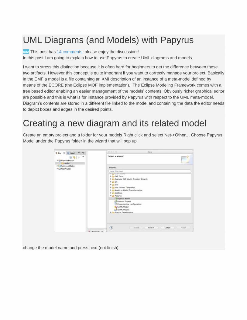
Creating a new diagram and its related model Create an empty project and a folder for your models Right click and select Net->Other… Choose Papyrus
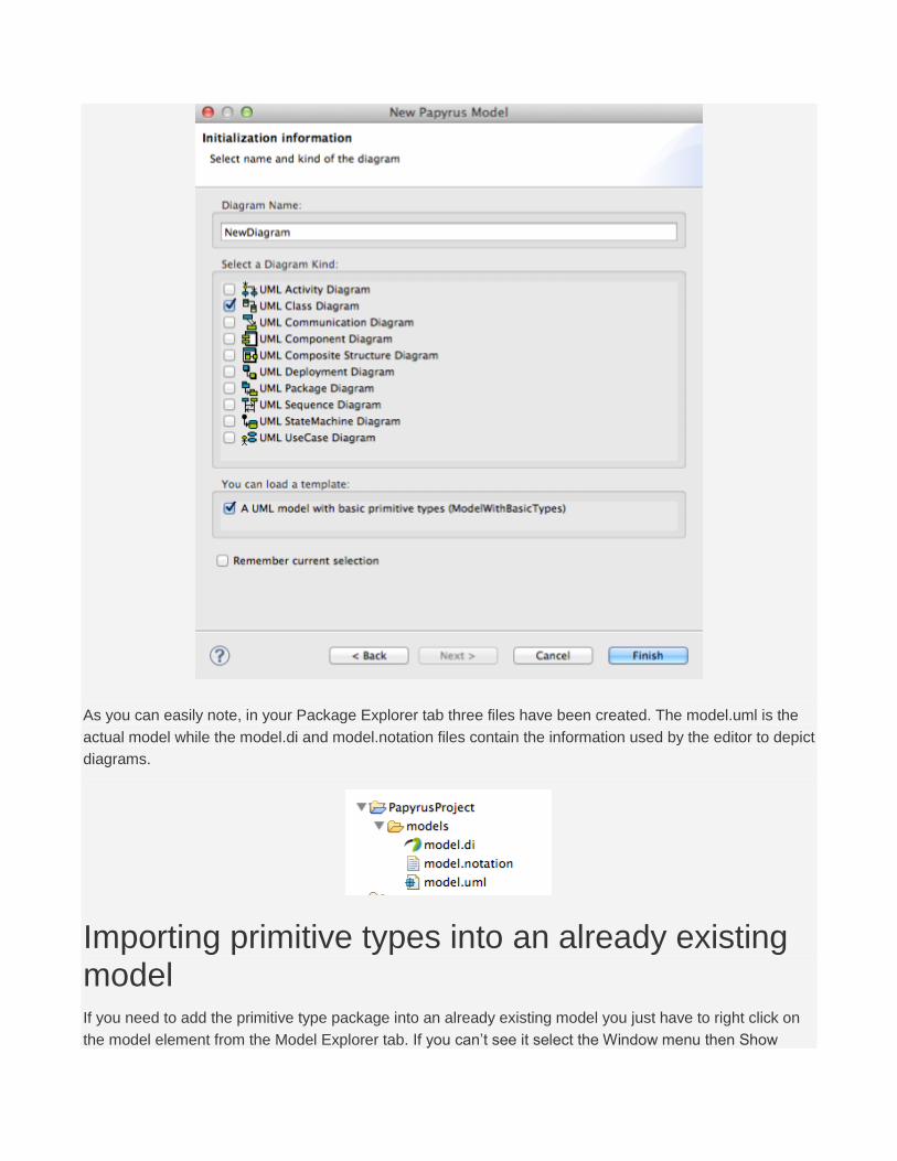
Model under the Papyrus folder in the wizard that will pop up
As you can easily note, in your Package Explorer tab three files have been created. The model.uml is the
actual model while the model.di and model.notation files contain the information used by the editor to depict
diagrams.
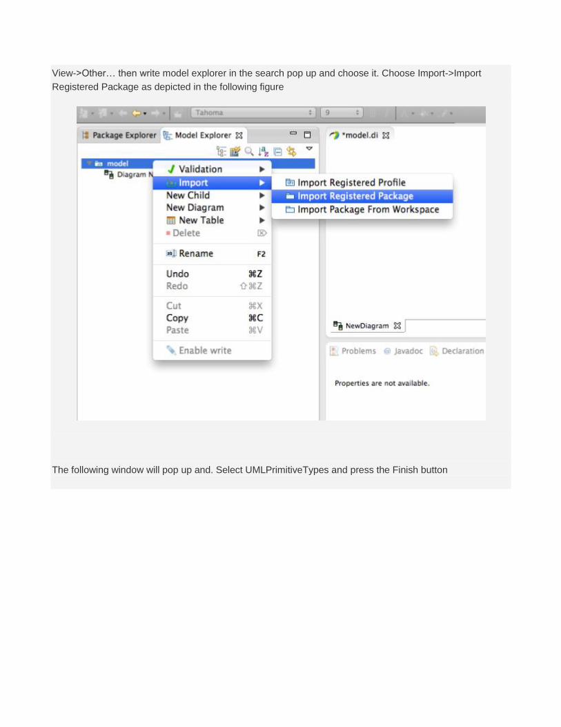
Importing primitive types into an already existing model If you need to add the primitive type package into an already existing model you just have to right click on
the model element from the Model Explorer tab. If you can’t see it select the Window menu then Show