UML-VT: A Formal Verification Environment for UML Activity Diagrams Zamira Daw, John Mangino, and Rance Cleaveland Department of Computer Science, University of Maryland Abstract—This paper introduces a translation tool that sup- ports formal verification of UML activity diagrams using the model checkers: UPPAAL, SPIN, NuSMV and PES. The moti- vation for this tool arises from the desire to check the properties of a system early in the development process, and the fact that UML is commonly used to describe software models. The tool is implemented as an Eclipse-plugin that automatically translates the UML activities and logical requirements into valid input notation for the model checkers. The automated aspect of the plugin allows users without a background in formal methods to verify the safety and liveness of a system. The translation strategies implemented in this plugin are the result of an experimental study. A tutorial video can be found in https://www.youtube.com/watch?v=AHsih8REUxM. I. I NTRODUCTION A major concern in system development is the correctness of software components. The benefit of formal methods is that they verify the systems correctness against specific require- ments for all possible inputs. In contrast to testing, formal methods allow not only the verification of the presence of an error in a system, but also the verification of the absence of errors. Automated formal verification such as model check- ing [1] has been improved in the last decades, allowing the verification of more complex software systems. However, the usage of model checking is limited by the required knowledge of formal methods, as well as by the state explosion problem, which restricts the size of systems that are verifiable. Model-driven development (MDD) has been used in soft- ware development in order to handle the development of complex systems. In MDD approaches, designers first build models of the desired software, which can be manually or automatically (code generation) transformed into develop- ment artifacts (e.g. source code). The models abstract ele- ments/behaviors of the systems, thereby reducing the com- plexity of the development and facilitating the understanding of the system. Unified Modeling Language (UML) [2] has attracted substantial attention as a language for MDD. More- over, UML is a non-proprietary, independently maintained standard, which provides several graphical sublanguages and an extension mechanism (profiling). A UML activity diagram is a behavioral diagram that is generally used to specify the workflow of a system. The presented tool uses UML activity diagrams in order to specify the behavior of the system. The UML Verification Tool (UML-VT) is meant to support the integration of model checking into a MDD process. The Research supported by NSF Grant CCF-0926194 purpose of this integration is to provide formal verification in the early phases of development regardless of ones knowledge of formal methods. Furthermore, the integration leverages the higher abstraction of the UML models in order to reduce the state explosion problem, thereby allowing the verification of more complex systems. The UML-VT transforms UML activities into the input notation for the model checkers: UPPAAL, SPIN, NuSMV and PES. The used transformation strategies have been chosen based on the results of an experimental study conducted by the authors [3]. This paper presents the capabilities and functionality of the UML-VT as well as references for theo- retical and technical work, on which this tool is based. The plugin and source code of the UML-VT can be found at http://www.cs.umd.edu/∼rance/projects/uml-vt/ II. FUNCTIONALITY The UML-VT is an open-source Eclipse plug-in that ver- ifies UML activities against given requirements using well- know model checker tools such UPPAAL [4], SPIN [5] and NuSMV [6], and an experimental model checker PES [7]. The inputs of the verification are the UML models and the requirements. The format of the UML models is *.uml, which can be exported from the majority of UML-Tools such as Papyrus 1 or MagicDraw 2 . Requirements have to be specified as a temporal logic formula, which can be created using a Requirement Editor provided by the UML-VT. The output of the verification is a report that shows the satisfiability of the given requirement and counter examples that violate the requirement (depending of the chosen model checker). The UML-VT also provides an Eclipse Perspective shown in Figure 1 in order to facilitate the verification workflow. The Perspective can be open by the following menu chain: Window → Open Perspective → Other → UML-VT. The perspective contains four views and one menu. View 1 shows the Project Explorer, View 2 is reserved for the chosen modeling tool, View 3 shows the Console which will update the user on the current state of the verification process, and View 4 displays the report file, which contains the results of the model checker. The UML-VT Menu allows the user to start the verification (Verify), to set the paths of the model checkers executable file (Configuration), and to set a default model 1 https://eclipse.org/papyrus/ 2 http://www.nomagic.com/products/magicdraw.html
Transcript
UML-VT: A Formal Verification Environment forUML Activity DiagramsZamira Daw, John Mangino, and Rance Cleaveland
Department of Computer Science, University of Maryland
Abstract—This paper introduces a translation tool that sup-ports formal verification of UML activity diagrams using themodel checkers: UPPAAL, SPIN, NuSMV and PES. The moti-vation for this tool arises from the desire to check the propertiesof a system early in the development process, and the factthat UML is commonly used to describe software models. Thetool is implemented as an Eclipse-plugin that automaticallytranslates the UML activities and logical requirements into validinput notation for the model checkers. The automated aspectof the plugin allows users without a background in formalmethods to verify the safety and liveness of a system. Thetranslation strategies implemented in this plugin are the resultof an experimental study. A tutorial video can be found inhttps://www.youtube.com/watch?v=AHsih8REUxM.
I. INTRODUCTION
A major concern in system development is the correctnessof software components. The benefit of formal methods is thatthey verify the systems correctness against specific require-ments for all possible inputs. In contrast to testing, formalmethods allow not only the verification of the presence of anerror in a system, but also the verification of the absence oferrors. Automated formal verification such as model check-ing [1] has been improved in the last decades, allowing theverification of more complex software systems. However, theusage of model checking is limited by the required knowledgeof formal methods, as well as by the state explosion problem,which restricts the size of systems that are verifiable.
Model-driven development (MDD) has been used in soft-ware development in order to handle the development ofcomplex systems. In MDD approaches, designers first buildmodels of the desired software, which can be manually orautomatically (code generation) transformed into develop-ment artifacts (e.g. source code). The models abstract ele-ments/behaviors of the systems, thereby reducing the com-plexity of the development and facilitating the understandingof the system. Unified Modeling Language (UML) [2] hasattracted substantial attention as a language for MDD. More-over, UML is a non-proprietary, independently maintainedstandard, which provides several graphical sublanguages andan extension mechanism (profiling). A UML activity diagramis a behavioral diagram that is generally used to specify theworkflow of a system. The presented tool uses UML activitydiagrams in order to specify the behavior of the system.
The UML Verification Tool (UML-VT) is meant to supportthe integration of model checking into a MDD process. The
Research supported by NSF Grant CCF-0926194
purpose of this integration is to provide formal verification inthe early phases of development regardless of ones knowledgeof formal methods. Furthermore, the integration leverages thehigher abstraction of the UML models in order to reduce thestate explosion problem, thereby allowing the verification ofmore complex systems.
The UML-VT transforms UML activities into the inputnotation for the model checkers: UPPAAL, SPIN, NuSMVand PES. The used transformation strategies have been chosenbased on the results of an experimental study conductedby the authors [3]. This paper presents the capabilities andfunctionality of the UML-VT as well as references for theo-retical and technical work, on which this tool is based. Theplugin and source code of the UML-VT can be found athttp://www.cs.umd.edu/∼rance/projects/uml-vt/
II. FUNCTIONALITY
The UML-VT is an open-source Eclipse plug-in that ver-ifies UML activities against given requirements using well-know model checker tools such UPPAAL [4], SPIN [5] andNuSMV [6], and an experimental model checker PES [7].The inputs of the verification are the UML models and therequirements. The format of the UML models is *.uml, whichcan be exported from the majority of UML-Tools such asPapyrus1 or MagicDraw2. Requirements have to be specifiedas a temporal logic formula, which can be created using aRequirement Editor provided by the UML-VT. The outputof the verification is a report that shows the satisfiability ofthe given requirement and counter examples that violate therequirement (depending of the chosen model checker).
The UML-VT also provides an Eclipse Perspective shownin Figure 1 in order to facilitate the verification workflow. ThePerspective can be open by the following menu chain: Window→ Open Perspective → Other → UML-VT. The perspectivecontains four views and one menu. View 1 shows the ProjectExplorer, View 2 is reserved for the chosen modeling tool,View 3 shows the Console which will update the user onthe current state of the verification process, and View 4displays the report file, which contains the results of the modelchecker. The UML-VT Menu allows the user to start theverification (Verify), to set the paths of the model checkersexecutable file (Configuration), and to set a default model
checker (Model checkers). This menu is only displayed if theUML-VT Perspective is active.
Fig. 1. Eclipse-Plugin of the UML-VT
The verification workflow is shown in Figure 2.Create project: A new project can be created using File →
New → Project → UML-VT → Project. The created projectcontains by default a Papyrus model, DMOSES Profile [8],and the Requirement file. The DMOSES Profile is explainedin the modeling section.
Fig. 2. Workflow of the UML-VT
Modeling: The user can model the system within thePapyrus model or using his/her preferred UML-Tool. However,note that the verification requires the file *.uml. If MagicDrawis used as modeling tool, this file can be obtained by File →Export To → Eclipse UML2. The DMOSES profile is a UMLprofile that extends UML activity diagrams and state machinediagrams in order to add information regarding execution time,parallelism and priority [8]. This profile gives an unambiguousbehavior specification, which is required for the formal veri-fication. An example of an extended UML activity is shownin Figure 3.
Requirements specification: The user can specify the re-quirements with in the file Requirements.tl using the Require-
ment Editor. The editor aims to facilitate the specificationof temporal logic formulas by highlighting keywords andchecking syntax. LTL and CTL formulas are supported. Theeditor syntax is model checker independent. An examplerequirement for the activity in Figure 3 can be ”In all executionpaths, the ActionB should be executed at least one time”. Thetemporal logic formula corresponding to the requirement is:
AF Activity2 :: ActionB (1)
AF Activity1 :: Action2 :: ActionB (2)
Note that equation 1 verifies the ActionB if the main activ-ity would be Activity2 and equation 1 verifies the same actionbut if the main activity would be Activity1. RequirementEditor provides code completions, which suggests a list ofpossible names of actions.
Fig. 3. UML activity example
Generation of model-checker specific properties: Once theRequirements.tl file is saved, model-checker specific formulasare generated in the scr-gen folder according to the chosenmodel checker. Formulas that are not supported by the givenmodel checker (e.g. UPPAAL only allows only a subset ofCTL∗ [9]) are not transformed into model-checker specificformulas and are shown in the console.
Translation from UML-models into model-checker lan-guages: The translation is started by clicking the Verify buttonin the UML-VT Menu. Depending on the chosen modelchecker a different translation is executed. The translationssupport hierarchical modeling and also apply optimizationtechniques. The generated files are saved in the scr-gen folder.These files are the input for the model checkers.
Fig. 4. Possible main activities to verify
Model checking execution: After a successful translation,a window pops up with a list of all possible main activitiesas shown in Figure 4. Thus, the user can select the mainactivity of the system, afterwards the chosen model checkeris automatically invoked. There is a timeout that limits theverification time.
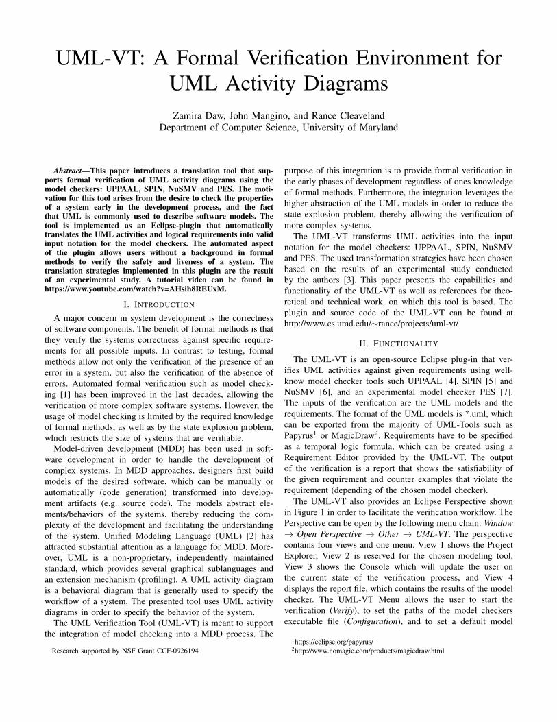
Display of verification results: The results of the verifica-tion are saved in the report.txt file and are displayed afterthe model checker has finished. Current efforts address amodel checker independent report in order to facilitate theunderstanding of the results. Figure 5 shows the verificationresult of the example in Figure 3 and the requirement offormula 2. Note that the property is not satisfied, which impliesthat the action is not executed. This is because the evente1 is sent only after it is received. Since there are no otheractivities that send this event, actions within Figure 3 are neverexecuted. Errors such as this one are not easy to find in a modelwith multiple activities and multiple hierarchical levels. Thisexample shows how the correctness of the model can be easilyverified using the UML-VT.
Fig. 5. Verification results of Formula 2 using UPPAAL
III. ARCHITECTURE
The UML-VT Eclipse-plugin can be divided into fourmain components: Model Transformation, Code Generation,a Requirement Editor, and a User Interface as is shown inFigure 6. The User Interface aims to facilitate the interactionwith the user by providing a Perspective, Menus, ProjectWizards, Plugin-Installation, Verification Management, etc.This component is primary based on the Rich Client Platform(RCP) provided by Eclipse.
Fig. 6. Architecture of the Eclipse-Plugin. Developed components (green)are based on Eclipse components (blue), and external plugins (orange).
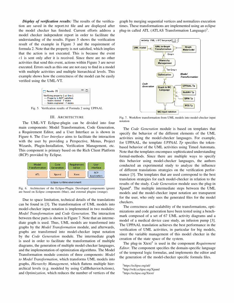
Due to space limitation, technical details of the translationscan be found in [3]. The transformation of UML models intomodel-checker input notation is implemented in two modules:Model Transformation and Code Generation. The interactionbetween these parts is shown in Figure 7. Note that an interme-diate graph is used. Thus, UML models are transformed intographs by the Model Transformation module, and afterwards,graphs are transformed into model-checker input notationby the Code Generation module. The intermediate graphis used in order to facilitate the transformation of multiplediagrams, the generation of multiple model-checker languages,and the implementation of optimization algorithms. The ModelTransformation module consists of three components: Modelto Model Transformation, which transforms UML models intographs, Hierarchy Management, which flattens multiple hier-archical levels (e.g. modeled by using CallBehaviorActions),and Optimization, which reduces the number of vertices of the
graph by merging sequential vertices and normalizes executiontimes. These transformations are implemented using an eclipseplug-in called ATL (ATLAS Transformation Language)3.
Fig. 7. Workflow transformation from UML models into model-checker inputnotation
The Code Generation module is based on templates thatspecify the behavior of the different elements of the UMLactivities using the model-checker languages. For example,for UPPAAL, the template UPPAAL Tp specifies the token-based behavior of the UML activities using Timed Automata.Note that the templates encompass sophisticated understandingformal-methods. Since there are multiple ways to specifythis behavior using model-checker languages, the authorsconducted an experimental study to analyze the influenceof different translations strategies on the verification perfor-mance [3]. The templates that are used correspond to the besttranslation strategies for each model-checker in relation to theresults of the study. Code Generation module uses the plug-inXpand4. The multiple intermediate steps between the UMLmodels and the model-checker input notation are transparentfor the user, who only sees the generated files for the modelcheckers.
The correctness and scalability of the transformations, opti-mizations and code generation have been tested using a bench-mark composed of a set of 67 UML activity diagrams and amodel of a medical device case study, an infusion pump [3].The UPPAAL translation achieves the best performance in theverification of UML activities, in particular for big models,since the variable management of this model checker in thecreation of the state space of the system.
The plug-in Xtext5 is used in the component RequirementEditor. The component specifies the domain-specific languageof the temporal logic formulas, and implements the editor andthe generation of the model-checker specific formula files.
To the best of our knowledge, there is an apparent lack oftools aimed at formal verification of UML activities. Althoughthere are different approaches that propose the verification ofUML activities using model checking, summarized in [3], themajority of these approaches do not provide a public tool(or it could not be found). Similar to the presented tool,these approaches use translational strategies to generate model-checker languages. In general, these approaches offer onlythe usage of one model checker. In contrast, the UML-VTsupports four model checkers, and provides an open-sourceEclipse plugin.
MADES project propose a tool chain [10] to verify UMLModel of embedded systems. MADES uses its own modelchecker. In [11], dos Santos also presents a formal verificationtool for UML behavioral diagrams using NuSMV. Similarto our approach, these tools presents translations from UMLmodel into the model-checker input notation. In contrast toUML-VT, these tools force the user to use only one modelchecker. Furthermore, the translations provided by the UML-VT are based on an experimental study providing a higherconfiability. It is worth mentioning that these tools where notavailable to download, and therefore the description is basedonly on academic publications.
V. DISCUSSION
The usage of UML models as an input notation of the ver-ification has three main advantages. 1) It is easier to integratethe verification in the MDD process because these models arealso used during the development process. 2) The abstractionof the UML models mitigates the state-explosion problemof the model-checking algorithm. Furthermore, the DMOSESprofile adds additional information about the implementation(e.g. execution time) that allows verifying the system takinginto account implementation features. The DMOSES profilesalso contributes to the reduction of the state-space since thisUML extension provides a deterministic behavior and reducesthe behavior concurrency by giving a limited processing units.These aspects allow the application of model checking withoutany further optimization methods (e.g. CEGAR). 3) SinceUML models are model-checker independent, model-checkerspecific translations can be implemented, which facilitate thechoice of the model checker. Although the choice of a modelchecker should primarily depend on its ability to address thesystem domain or the properties to verify, in practice, themodel checker is chosen based on the previous experienceof the formal method experts. Thus, the support of multiplemodel checkers by the UML-VT allows users to use the mostadequate model checker for the application area (e.g. UPPAALfor real-time systems or SPIN for distributed systems).
VI. CONCLUSION AND FUTURE WORKS
The UML-VT enables formal verification of UML activitiesusing model checkers. The tool is implemented in Eclipse,which is already known as a modeling and MDD environment.In order to facilitate the integration to any MDD process, the
tool allows the verification of models with an EMF inputformat, which can be exported from the majority of UML-Tools. The UML-VT supports the verification using the modelcheckers UPPAAL, SPIN, NuSMV, and PES. The support ofmultiple model checkers allows the user to choose the mostappropriate model checker with respect to the target platform.Generation of model-checker input notation is based on model-to-model transformations, which optimize the space state ofthe system, and on templates, which encompass the knowledgeof a model-checking expert. These templates are also tied toour interpretation of the UML models, which is based onthe DMOSES profile. This limitation can be overcome byextending the transformations in order to support other UMLprofiles or other diagrams.
In our ongoing work, we address this limitation in a moregeneral way by allowing the user to specify its own formalsemantics by using an extensible formal semantics [12]. Theextensible semantics provides a reference semantics that can beextended according to the interpretation of the UML models.A label transition system (LTS) is generated from the inputUML models according to the user-specific semantics. TheLTS formally specifies the behavior of the system. We areworking in a semantics framework tool that allows specifyingthe extensible semantics, and provides simulation of the UMLmodels, consistency verification of the semantics (bisimula-tion) and formal verification (translation from LTS into model-checker input notation) based on the user-specific semantics.
REFERENCES
[1] C. Baier, J.-P. Katoen et al., Principles of model checking. MIT pressCambridge, 2008, vol. 26202649.
[2] OMG, Unified Modeling Language, Superstructure, Version 2.4.1,http://www.omg.org/spec/UML/2.4.1/Superstructure/PDF, 2011.
[3] Z. Daw and R. Cleaveland, “Comparing model checkers for timed umlactivity diagrams,” Science of Computer Programming, 2015.
[4] G. Behrmann, A. David, and K. Larsen, A Tutorial on Uppaal.Springer Berlin Heidelberg, 2004, vol. 3185, pp. 200–236. [Online].Available: http://dx.doi.org/10.1007/978-3-540-30080-9 7
[5] G. J. Holzmann, “The model checker spin,” IEEE Transactions onSoftware Engineering, vol. 23, no. 5, pp. 279–295, 1997.
[6] A. Cimatti, E. Clarke, E. Giunchiglia, F. Giunchiglia, M. Pistore,M. Roveri, R. Sebastiani, and A. Tacchella, NuSMV 2: AnOpenSource Tool for Symbolic Model Checking. Springer BerlinHeidelberg, 2002, vol. 2404, pp. 359–364. [Online]. Available:http://dx.doi.org/10.1007/3-540-45657-0 29
[7] D. Zhang and R. Cleaveland, “Fast on-the-fly parametric real-time modelchecking,” in Real-Time Systems Symposium, 2005. RTSS 2005. 26thIEEE International, Dec 2005, pp. 10 pp.–166.
[8] Z. Daw and M. Vetter, Deterministic UML Models for InterconnectedActivities and State Machines. Springer Berlin Heidelberg, 2009, vol.5795, pp. 556–570.
[9] A. Pnueli, “The temporal logic of programs,” in Foundations of Com-puter Science, 18th Annual Symposium on. IEEE, 1977, pp. 46–57.
[10] A. Radjenovic, N. Matragkas, R. F. Paige, M. Rossi, A. Motta, L. Baresi,and D. S. Kolovos, “Mades: a tool chain for automated verificationof uml models of embedded systems,” in Modelling Foundations andApplications. Springer, 2012, pp. 340–351.
[11] L. B. R. dos Santos, E. R. Eras, V. A. de Santiago Junior, and N. L.Vijaykumar, “A formal verification tool for uml behavioral diagrams,”in Computational Science and Its Applications–ICCSA 2014. Springer,2014, pp. 696–711.
[12] Z. Daw and R. Cleaveland, “An extensible operational semantics for umlactivity diagrams,” in International Conference on Software Engineeringand Formal Methods, 2015.


![, VT[5] LIVE! and VT[5] LIVE SDI! VT[5] VT[5]LIVE] VT[5 ... · Virtual Studios SDI switcher HD/SD Editing VT[5] ... FEATURES Live video mixer ... Dual-channel upstream Effects bus](https://static.documents.pub/doc/80x56/5b0b5ac27f8b9ae61b8da9b2/-vt5-live-and-vt5-live-sdi-vt5-vt5live-vt5-studios-sdi-switcher.jpg)


