40
Maxiflex Dual Hart NIM M1589

Maxiflex Dual Hart NIM M1589
UMM1589R11.pdf - 2 - Copyright Omniflex
SCOPE:
The HART protocol is a comprehensive open communications standard for configuring and communicating with Smart field devices in industrial process
applications.
The Maxiflex M1589 Dual Hart NIM (NIM) is a Network Interface Module that acts as a permanent host interface device (primary master) on up to two Hart networks. This NIM is used to acquire data from the HART loops and to make the data available for SCADA, data-logging etc. in the Maxiflex system. Other specialised functions may be performed using the optional custom query block
mechanism.
This document describes the installation, set-up and use of the M1589 Hart NIM module in a Maxiflex system.
The reader is assumed to have a working knowledge of the Maxiflex system, and in particular the use of Data Interchange Table Registers (DIT’s) for the
reading and writing of data in the module.
UMM1589R11.pdf - 3 - Copyright Omniflex
DATE REVISION COMMENTS April 1999 1 Initial revision June 1999 2 Custom Query Block functions added. October 1999 3 Corrections to DIT layout February 2000 4 Added Table of Contents October 2003 5 Added query status DITs November 2003 6 Added HART status bytes to DIT.
Allow DIT to be user configurable. Added response data formatting blocks.
January 2004 7 Moved one shot query trigger location October 2004 8 Added retry count to DIT May 2005 9 Added Burst Mode functionality. Software Version has
progressed to Ver2.00. S.R
August 2005 10 Added Priority Poll Timers. Software version has progressed to V2.02
July 2007 11 Added Loop Inhibit function. Software Version 2.06
COPYRIGHT AND PROTECTIVE NOTICES 1. The Copyright of this document and the associated drawings, is the property of Omniflex and
is issued on condition that it is not copied, reprinted or reproduced or transmitted in any form or by any means, electronically, photocopying, mechanical or otherwise, nor its contents disclosed, either wholly or in part, without the consent in writing of, or in accordance with the conditions of a contract with Omniflex.
2. The publication of information in the document does not imply freedom from patent or other protective rights of Omniflex or others.
3. Although every intention is made to ensure that performance figures and data are accurate the company reserves the right to alter without notice any product or specification. Performance figures and data must therefore be specifically confirmed by the company before they become applicable to any tender, order or contract.
4. In the case of electrical components, enough data is included in the drawings to allow maintenance of the equipment. However, if component availability or substitution information is required please consult the factory for assistance, as it is impossible to include data on every component in this document.
5. This product is sold without liability for consequential loss of any description.

UMM1589R11.pdf - 4 - Copyright Omniflex
Table of Contents 1. Introduction ..............................................................................................................................5 2. Specifications...........................................................................................................................5 3. The HART Protocol ..................................................................................................................7
3.1 Background to the HART Protocol ......................................................................................7 3.2 Application of the HART Protocol........................................................................................7 3.3 Technical Features of the HART Protocol...........................................................................7 3.4 The M1589 Dual HART NIM in a HART loop. .....................................................................8
4. Installation ................................................................................................................................9 4.1 Installing the NIM on to a Maxiflex Base. ............................................................................9 4.2 Connecting the HART Loops...............................................................................................9 4.3 Typical Connection Diagrams .......................................................................................... 10
5. Operation .............................................................................................................................. 12 5.1 Hart Loop Independence.................................................................................................. 12 5.2 Philosophy of Operation ................................................................................................... 12 5.3 LED Indication .................................................................................................................. 12 5.4 Device Identification ......................................................................................................... 13 5.5 Burst Mode Operation ...................................................................................................... 13 5.6 Priority Polling Operation.................................................................................................. 14
6. Configuration......................................................................................................................... 16 6.1 Basic Configuration .......................................................................................................... 16 6.2 Customising the DIT Layout ............................................................................................. 16 6.3 Configuring Custom Query Blocks ................................................................................... 16 6.4 Burst Mode Configuration................................................................................................. 18
7. DIT Layout............................................................................................................................. 20
UMM1589R11.pdf - 5 - Copyright Omniflex
1. Introduction The M1589 Hart ® NIM module is an intelligent I/O module in the Maxiflex range of products. The Hart NIM plugs into an I/O slot on a Maxiflex base and independently interrogates field devices on two Hart networks, making the data available to the Maxiflex system.
This data may be accessed by the entire range of Maxiflex CPU’s. The method of access may vary from CPU to CPU, and reference should be made to specific documentation for these products for details of the implementation.
2. Specifications
Inputs/Outputs Number of HART loops 2
Number of Field devices interrogated 15 max per HART loop
HART Operating Mode Primary Master
Loop Isolation Voltage 500V dc min.
Maximum Loop Voltage 40Volts
Minimum loop load resistance 230ohms
Maximum loop load resistance 1100ohms
HART Transmitter signal levels 400mV p-p min
600mV p-p max
HART Receiver sensitivity 120mV p-p min
2000mV p-p max
HART Receiver threshold (Must ignore) 80mV
DC load impedance 2microamps max at 60deg C 40Volts
AC load impedance 22 microFarads typical

UMM1589R11.pdf - 6 - Copyright Omniflex
HART Wiring Recommendations Maximum Cable Impedance R x C must be less than 65us
(e.g. 300ohms x 0.2uF = 60us) (R includes load resistance) (C includes field device capacitance)
Cable Type Overall screen recommended Individually screened pairs over 1500m
Loop Power Supply Maximum Ripple 0.2V p-p (47-125Hz)
Loop Power Supply Maximum Noise 1.2mV (500Hz – 10kHz)
Loop Power Supply Impedance 10ohms
Supported HART Commands as standard Universal Commands
Command 0 Identify Manufacturer, Device Type and Revision Levels.
Command 3 Read Current and four (predefined) dynamic variables.
Other Commands User Configurable Up to 64 Custom Query Blocks may be
configured in the NIM. Each query block can address any HART device with any command support supported by that device.
The response is stored in its raw data format in the Data Interchange Table for interpretation by the user.
UMM1589R11.pdf - 7 - Copyright Omniflex
3. The HART Protocol 3.1 Background to the HART Protocol HART is an acronym for “Highway Addressable Remote Transducer”. The HART® protocol was originally developed by Rosemount Inc. but all rights in the protocol have now passed to the HART Communication Foundation, and the HART protocol is now freely available for general use. There is an abundance of information on the HART protocol available from a number of sources. The following Internet web-site is a recommended starting point for further reading: • The HART Communication Foundation at http://www.hartcomm.org
3.2 Application of the HART Protocol The HART protocol specifies a means for superimposing a digital messaging system on top of a conventional 4-20mA instrumentation loop to allow the remote interrogation and configuration of field devices. The operation of the HART system via the two wire 4-20mA loop does not affect the accuracy of the dc current in the loop.
3.3 Technical Features of the HART Protocol The HART protocol superimposes a Bell 202 Standard frequency-shift-keying signal at 1200 baud as an ac signal at a low level on the current loop. HART is a master/slave protocol. The field devices act as slaves in the protocol and only reply to requests addressed to them. Up to 15 slave devices may be connected on to a single pair of wires. In this multi-drop configuration, the field devices disable their 4-20mA signals and communication is exclusively via the HART protocol. When only a single slave device is present, then both the 4-20mA and HART communication may operate simultaneously. The protocol allows for two masters to be present on a single HART loop. These are typically a permanently connected control system (known as the primary master) and a hand-held configuration device known as a HART Communicator (acting as a secondary master). The command messages defined in the HART protocol are broken into three groups: 1. The “Universal” commands are implemented in all field devices. 2. The “Common-Practice” commands provide functions common to many field devices,
but may not be installed in the device. 3. The “Device-Specific” commands provide functions that are unique to a particular
manufacturer’s device.
UMM1589R11.pdf - 8 - Copyright Omniflex
The HART “Device Description Language” (DDL) is a formal language that allows a manufacturer to completely specify the communication interface to its HART equipped field device. This includes a definition of accessible variables, commands and operating procedures. It also includes a menu structure that a host device can use for a human operator. Device Descriptions make it easy to upgrade master devices to support new devices as they become available.
3.4 The M1589 Dual HART NIM in a HART loop. The M1589 Dual HART NIM is equipped with two independent HART primary master interfaces. This allows this product to communicate independently with two separate HART loops at the same time. The NIM implements a subset of the universal commands and does not require DDL files to configure the device. The list of commands implemented is defined later in this document. The NIM is designed to be self-configuring for ease of use. Once powered up, the NIM searches for HART devices on each of its two HART interfaces and builds an inventory of devices found. Various data elements are continuously and automatically read from the device and stored in the Data Interchange Table (DIT) in the device for access by the rest of the Maxiflex system. The NIM in this mode uses HART commands 0 and 3 to extract the most commonly used data from the field devices with no configuration necessary. The NIM is also provided with a custom query block mechanism. Up to 64 custom query blocks may be configured to perform specialised data manipulation on the connected field devices using any of the command types supported by the field device.
UMM1589R11.pdf - 9 - Copyright Omniflex
4. Installation
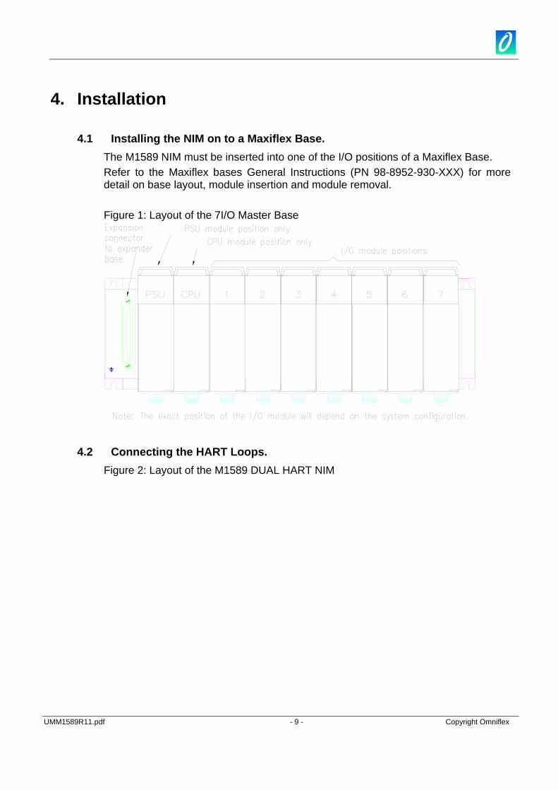
4.1 Installing the NIM on to a Maxiflex Base. The M1589 NIM must be inserted into one of the I/O positions of a Maxiflex Base. Refer to the Maxiflex bases General Instructions (PN 98-8952-930-XXX) for more detail on base layout, module insertion and module removal. Figure 1: Layout of the 7I/O Master Base
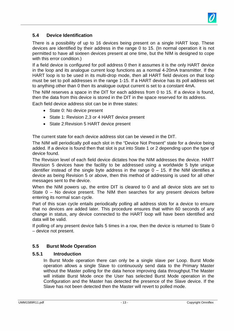
4.2 Connecting the HART Loops. Figure 2: Layout of the M1589 DUAL HART NIM

UMM1589R11.pdf - 10 - Copyright Omniflex
Note: The LED indicators can only be seen when illuminated.
PORT1
M1589A HART NIM
Tx
Rx
NIM OKPORT2
Tx
Rx
Wiri
ngac
cess
M1589 DUAL HART NETWORK INTERFACE
MODULE
NOTE: Loop connections are polarity
insensitive
21
PORT1
21
PORT2
A two-way connector is provided for each HART interface. This interface is completely isolated from the NIM circuitry and therefore will not affect the performance of a 4-20mA loop when connected. The connection is symmetrical, and may be connected with either polarity without affecting the performance of the system. It is NOT recommended that this connection be made while the 4-20mA loop is active, as a small current upset may be observed when the NIM circuit’s blocking capacitors charge.
4.3 Typical Connection Diagrams

UMM1589R11.pdf - 11 - Copyright Omniflex
A
B
C
B
C
Two Wire Transmitter Connection
Four Wire Transmitter Connection
The HART NIM may be connected across A-B or B-C

UMM1589R11.pdf - 12 - Copyright Omniflex
5. Operation 5.1 Hart Loop Independence The NIM operates two completely independent polling procedures, one for each HART loop. The following description applies to either of these HART loops.
5.2 Philosophy of Operation In accordance with the Maxiflex inter-networking philosophy, the design of the M1589 Dual HART NIM has been designed for maximum flexibility and ease of use. The HART NIM is designed as an interrogation device to be used for the purpose of exchanging live plant data with a number of HART devices for data acquisition, monitoring and data-logging applications. The HART NIM is not designed to replace the field device manufacturer’s recommended set-up tools or procedures. The configuration requirements for the NIM have been kept to a minimum. In most applications, no configuration at all is required, because the NIM automatically identifies the presence of field devices on the HART network, and begins polling for the most popular field device configuration and dynamic data. This data is automatically stored in the NIM’s Data Interchange Table (DIT) from where it can be read by the rest of the Maxiflex system in the conventional manner. Upon power up, the NIM begins an automatic polling sequence on each of the HART loops (using universal HART command 0), and identifies any devices present on the loops. The presence and identification of these field devices is made available in the DIT. Dynamic data is then read on a regular basis (using universal HART command 3) from these devices and is made available in the DIT. The NIM continues to poll on a regular but infrequent basis for the presence of any additional field devices in the loop (using universal HART command 0), and automatically begins polling these devices (using universal HART command 3) when found. If a device is removed from the loop, then this is detected and the DIT updated accordingly.
5.3 LED Indication Name Colour Indication NIM OK GREEN Steady ON - module healthy
OFF or Flashing – module unhealthy (except on startup) PORT1 Rx YELLOW Flashes when a message is received on Loop 1 PORT1 Tx RED Flashes when a message is transmitted on Loop 1 PORT2 Rx YELLOW Flashes when a message is received on Loop 2 PORT2 Tx RED Flashes when a message is transmitted on Loop 2
Note that the NIM module always polls for new devices. This means that the transmit (Tx) LEDs will flash continuously, even there are no devices connected to that loop.
UMM1589R11.pdf - 13 - Copyright Omniflex
5.4 Device Identification There is a possibility of up to 16 devices being present on a single HART loop. These devices are identified by their address in the range 0 to 15. (In normal operation it is not permitted to have all sixteen devices present at one time, but the NIM is designed to cope with this error condition.) If a field device is configured for poll address 0 then it assumes it is the only HART device in the loop and its analogue current loop functions as a normal 4-20mA transmitter. If the HART loop is to be used in its multi-drop mode, then all HART field devices on that loop must be set to poll addresses in the range 1-15. If a HART device has its poll address set to anything other than 0 then its analogue output current is set to a constant 4mA. The NIM reserves a space in the DIT for each address from 0 to 15. If a device is found, then the data from this device is stored in the DIT in the space reserved for its address. Each field device address slot can be in three states:
• State 0: No device present • State 1: Revision 2,3 or 4 HART device present • State 2:Revision 5 HART device present
The current state for each device address slot can be viewed in the DIT. The NIM will periodically poll each slot in the “Device Not Present” state for a device being added. If a device is found then that slot is put into State 1 or 2 depending upon the type of device found. The Revision level of each field device dictates how the NIM addresses the device. HART Revision 5 devices have the facility to be addressed using a worldwide 5 byte unique identifier instead of the single byte address in the range 0 – 15. If the NIM identifies a device as being Revision 5 or above, then this method of addressing is used for all other messages sent to the device. When the NIM powers up, the entire DIT is cleared to 0 and all device slots are set to State 0 – No device present. The NIM then searches for any present devices before entering its normal scan cycle. Part of this scan cycle entails periodically polling all address slots for a device to ensure that no devices are added later. This procedure ensures that within 60 seconds of any change in status, any device connected to the HART loop will have been identified and data will be valid. If polling of any present device fails 5 times in a row, then the device is returned to State 0 – device not present.
5.5 Burst Mode Operation 5.5.1 Introduction
In Burst Mode operation there can only be a single slave per Loop. Burst Mode operation allows a single Slave to continuously send data to the Primary Master without the Master polling for the data hence improving data throughput.The Master will initiate Burst Mode once the User has selected Burst Mode operation in the Configuration and the Master has detected the presence of the Slave device. If the Slave has not been detected then the Master will revert to polled mode.

UMM1589R11.pdf - 14 - Copyright Omniflex
5.5.2 Master in Burst Mode and Slave in Polled Mode after Power on Reset The configuration in the HART NIM is retained after a power on reset. Therefore if the Master was set to Burst and the Slave is in Polled Mode, then there will be no communication between the Master and the Slave until the Master is set to Polled Mode. Then if you recycle power the Master will start communicating with the Slave. At this point if you wish for the Slave to be in Burst Mode then you can configure the Slave by selecting Burst Mode in the configuration register for that Loop once the Master has detected the Slave in Polled Mode.
5.5.3 Master in Polled Mode and Slave in Burst Mode after Power on Reset
If the Master was set to Polled mode and the Slave is in Burst mode then you will need to set the configuration to Burst Mode then recycle power to the Master, this will prevent the master from transmitting to the Slave which is already in Burst Mode. Now if you wish to switch the Slave to Polled Mode you can simply select Polled Mode in the configuration register for that Loop.
5.5.4 Master in Polled Mode and Slave in Polled Mode after Power on Reset If both the Master and the Slave are in Polled Mode then after a power on reset the Master will try to detect the Slave and once this has happened, then the Master will get the data from the Slave and store it in the Loop n - Device x, x is the ID of the Slave when in Polled Mode. Refer to the GROUP NIM Dynamic Data and the item Loop n Devices Present to determine where to find the Dynamic data for that Slave.
5.5.5 Master in Burst Mode and Slave in Burst Mode after Power on Reset If both the Master and Slave are in Burst Mode after a power on reset then the Slave's Dynamic data will be stored in in Loop n - Device 0 Data GROUP in DITView, n is the Loop number to which the slave is connected. If you wish to switch the Slave to Polled Mode you can simply select Polled Mode in the configuration for that Loop and write it to the target. The Dynamic Data for the Slave will no longer appear in Loop n - Device 0 Data but will rather appear in the GROUP pointed to by the Slave ID. Refer to the GROUP NIM Dynamic Data and the item Loop n Devices Present to determine where to find the Dynamic data for that Slave.
5.6 Priority Polling Operation 5.6.1 Introduction
This feature allows the User to prioritise the rate at which the transmitters are polled by the Master. This is done using Configurable Transmitter Polling Rates. These configurable timers will allow the User to adjust the rate of polling of each device on each loop as per the User's requirements to allow the User to customise the data throughput. The User can switch between Manual and Automatic mode of Operation. Manual mode uses the Configurable Timers to decide whether to poll the transmitter or not also how often to poll the transmitter. In automatic mode all transmitters are polled at the same rate and the Poll Timer Configuration is ignored.
UMM1589R11.pdf - 15 - Copyright Omniflex
5.6.2 Automatic Polling
When automatic polling is selected for the loop, all transmitters are polled at the same rate. After every 7 cycles of polling, the Master will search for a device which is not Online. If the device is found then it will be switched to Online. When Automatic polling is selected the Programmable Poll Timers for each loop are ignored.
5.6.3 Manual Polling When Manual polling is selected for the loop, all transmitters connected to the loops are polled according to the Poll Timer setting rate. If the Poll Timer is set to “Do Not Poll” then that slave device will be ignored by the polling engine. The User can select from a range of polling rates which range from As fast as Possible to 5 seconds per device. The polling engine will only search for Offline devices that have their poll timers configured.
5.6.4 Inhibit Polling In specialized applications where the two HART NIM modules are used in a redundant switch over configuration, two HART NIMs are connected to the same loop. One module is the active module whilst the other is in standby, ready to be made active if the active module becomes faulty. In order to operate this way, it is necessary to inhibit the transmitter of the standby NIM module so as not to cause conflict on the current loop. A special Dynamic DIT register (DIT 91) is used for this purpose, where a single bit is used to control the transmitter of each port. These bits are to be controlled by Maxiflex CPU program only and are always cleared on startup i.e. transmitter always enabled. Refer to the DIT layout for more details.
UMM1589R11.pdf - 16 - Copyright Omniflex
6. Configuration 6.1 Basic Configuration No configuration is necessary for the HART NIM to operate in its basic polling state. Once connected and powered up, the NIM automatically begins polling all addresses on the HART loop identifying any HART field devices present on the loop. The NIM then reads the specified data from the device and stores it in the DIT to be accessed by the Maxiflex CPU in the system. It can take up to 60 seconds after power up for the data to become valid in the DIT. The validity of data may be checked by monitoring DIT Registers 100 and 101. These registers identify the presence of valid data for field devices by setting the corresponding bits in the DIT. If the bit is clear, then the data in the DIT for that device is not valid. The layout of the DIT as shown in section 7 is the default layout when the HART NIM is shipped. It is possible to optimise this layout for each application. This technique is described in the next section.
6.2 Customising the DIT Layout The default setting when the HART NIM is shipped is for the static and dynamic data for each device to be stored in the range 200 to 973 for Loop 1 and 1200 to 1973 for Loop 2. The default settings for each device are defined in the table in section 7. It is possible to customize this layout. The reason that this may be useful is to compact the data for easier retrieval particularly if fewer than the maximum number of devices is to be used. By this means it is possible to order the data returned by the basic polling routine, as well as that returned by custom queries (see next section) as required. To customise the DIT layout, change the default settings in DIT registers 3900 to 3963. Note that care must be taken to ensure that reserved registers are not overwritten and that device data does not overlap. A useful feature is that it is possible to ignore a device’s data by entering a DIT address of 0 for both its static and dynamic settings. It is also possible to customise the storage area for custom query (refer to next section) status and command response codes. Two registers per query in use should be reserved for this purpose.
6.3 Configuring Custom Query Blocks 6.3.1 Introduction
The user can configure up to 64 Custom Query Blocks in the NIM. Each query block can contain any valid HART command and can address any device on either of the HART loops. Each Query Block can be configured as a “one-shot” query that is triggered by the user, or can be configured as a cyclic query where the Query is triggered on a regular basis by the NIM. The status of each Query is presented in the Query Status DIT registers. These registers indicate the success or failure of each query last time it was sent.

UMM1589R11.pdf - 17 - Copyright Omniflex
6.3.2 Polling Sequence As described above, the NIM automatically identifies all field devices present on each HART loop and polls each present device in turn using HART command 3. After the Command 3 sequences to all present devices have been completed, all Custom Query Blocks ready to execute are then triggered in turn. The NIM then returns to execute the command 3 queries to all present devices, and the cycle repeats. This is known as a complete polling sequence.
6.3.3 Controlling the Execution of a Custom Query Block Each Custom Query Block has a Control Register used to control the Query Block. If this register is set to 0 then the query block is disabled. If a value “n” between 1 and 255 is stored into this register then the Query block acts as cyclic query, and the Query is triggered every “n” number of polling sequences. To use the query as a one shot (sent once on command), set the control register to zero and use the one shot query trigger bits to initiate it.
6.3.4 Setting the device to be addressed by a Custom Query Block The least significant byte of this register holds the polling address of the field device to be polled using this query block. For devices on HART loop 2, the polling address is derived by adding 16 to the actual address. i.e. Polling addresses 0 to 15 refer to HART Loop 1, and polling addresses 16-31 refer to HART Loop 2. If the device is a HART revision 5 device, then the NIM will use the device’s corresponding unique identifier to address it in this Query Block provided the device is currently online.
6.3.5 Setting the command type in a Custom Query Block For each Query Block, the HART command to be used is specified in the third register of the query block along with two other items. The Command is a single byte number in the range 0 to 153 as specified by the HART protocol. The command to be used in this query block must be stored in the least significant byte of this DIT register.
6.3.6 Setting the Data to be transmitted in a query Some HART commands require that data be included in the message transmitted to the field device. Store the number of bytes to be transmitted in the most significant byte of the third DIT register in the query block. This is a count of the number of actual data bytes to be transmitted and excludes any header information and checksum in the transmitted message. The HART protocol specified that this count is limited to 25 bytes of data. If there is no data associated with the command then this byte count must be set to 0. Store the actual data bytes to be transmitted in any free area of the NIM’s DIT, packed 2 bytes per register, starting in the least significant byte position of the first register. Store the DIT start address of the data in the fourth register in the Query Block.

UMM1589R11.pdf - 18 - Copyright Omniflex
If this data is to be changed dynamically by the user, then it should be stored in the dynamic DIT area (from address 100 to 2999). If the data can be pre-configured, and you wish this data to be retained on power down, then store it in the unreserved static configuration area of the DIT (from address 3220 to 3999). Care should be taken in the allocation of DIT space for this data to avoid overwriting other data inadvertently.
6.3.7 Setting the destination of the received data from a Query Block. Some HART commands return data as part of the reply. This data will be written to the DIT in an area specified in the query block. Store the DIT address where you wish the start of the returned data to be written in the fifth register in the Query Block. By default, the data will be written packed two bytes to a register, however it is possible to format the way in which the data is stored as explained in the next two sections.
6.3.8 Setting an offset to the start of response data. Many HART response messages have a mixture of single byte and multi-byte data. As a result, it is sometimes convenient to start storing the returned data in the most significant byte of the first DIT register. This will allow multi-byte data later in the message to be conveniently contained in a one or two DIT registers instead of split across DIT Register boundaries. This can be achieved by setting the Receive Data Offset Bit which is the most significant bit of the third Query Block register (sharing space with the byte count and command type). Set this bit to start the returned data storage in the most significant byte of the first register. The least significant byte will then be set to zero. Clear this bit to start the data storage in the least significant byte of the first DIT register.
6.3.9 Specifying a format for response data. Where further formatting of the response data is required, use can be made of the response formatting blocks. These blocks facilitate the specification of the exact order and position that every byte in the response is stored in the DIT. Each block consists of 25 registers to cater for the maximum of 25 bytes in a HART response. Each register in a block can be configured to specify the byte number (data) from the response that should be stored in either the least or most significant byte of the corresponding DIT register. Up to 16 such format blocks may be configured, and any number of queries may reference a single format block. Note that a query that uses a format block, will ignore the receive data offset setting as described in the previous section.
6.4 Burst Mode Configuration To configure a Loop for Burst Mode or Polled Mode operation select the GROUP labelled Busrt Mode Configuration and select the item you wish to configure depending on the Loop you wish to setup for Burst Mode by right clicking on that item then select the configuration of your choice for that Loop either Burst Mode if you want to configure the Slave for Burst Mode operation or Polled Mode if you wish to
UMM1589R11.pdf - 19 - Copyright Omniflex
exit Burst Mode operation. Refer to Section 7 DIT Layout for the DIT address of these configuration items.
6.5 Automatic/Manual Polling Configuration 6.5.1 Automatic Polling
To configure a loop for Automatic Polling, using Omniset and the latest M1589 configuration template select the GROUP labelled Configuration->Advanced Settings->Poll Priority Timers and then double click on the ITEM labelled Polling Method Loop1 to set Loop1 or Polling Method Loop2 to set Loop2 to Automatic Polling. Once you have changed the configuration for the desired Loop to Automatic Polling you can then write that GROUP to the Target, by clicking on the Write Current Group to Target TAB.
6.5.2 Manual Polling To configure a loop for Manual Polling, using Omniset and the latest M1589 configuration template select the GROUP labelled Configuration->Advanced Settings->Poll Priority Timers and then double click on the ITEM labelled Polling Method Loop1 to set Loop1 or Polling Method Loop2 to set Loop2 to Manual Polling. You will also need to setup the Devicex Timer Config ITEMS for that Loop, to do this simply double click on the Device ITEM of choice and select the Poll Rate from the drop downlist. Once you have changed the configuration for the desired Loop to Manual Polling Operation you can then write that GROUP to the Target, by clicking on the Write Current Group to Target TAB.

UMM1589R11.pdf - 20 - Copyright Omniflex
7. DIT Layout
The HART NIM has the following DIT layout: Note that certain areas of the DIT can be relocated. Therefore the DIT numbers shown in this table are only the default addresses.
DIT No. DESCRIPTION COMMENT
Live Data Storage Area
0-99 COMMON MODULE DATA AREA
0 Product Code = 0x159 Uniquely identifies the HART NIM
1 DIT Revision Number Specifies register layout supported by the NIM
2 Kernel Version Current Firmware Version
3 Supported Services
4 User Tag Allows a unique identifier to be configured for each NIM. Once setup, the Omniflex configuration packages will warn the user if the tag name in the configuration file does not match that in the target.
5 User Tag
6 User Tag
7 User Tag
8-21 Reserved
22 System Register
23 Alive Counter
24-99 Reserved
91 LOOP INHIBIT
91 Inhibit Loop transmitters. The transmitter of each loop can be disabled to allow the loop to act as a standby loop for redundant/fail-over applications.
Bit 0: Loop 1: 1 to inhibit, 0 to enable
Bit 1: Loop 2: 1 to inhibit, 0 to enable
Bits 2 to 15 not used.
All bits are cleared on startup.
92-95 ONE SHOT QUERY TRIGGER BITS
92 One Shot Query Trigger Bits for Queries 1 to 16.
This register facilitates the triggering of HART queries on a one shot basis from an application program or SCADA/DCS etc. By setting a bit to 1, the associated query will be triggered on the next query cycle. Once the query has been executed, the bit is automatically reset to 0.
UMM1589R11.pdf - 21 - Copyright Omniflex
93 One Shot Query Trigger Bits for Queries 17 to 32.
As for DIT 92
94 One Shot Query Trigger Bits for Queries 33 to 48.
As for DIT 92
95 One Shot Query Trigger Bits for Queries 49 to 64.
As for DIT 92
96-99 Reserved
100-107 HART NIM DYNAMIC DATA
100 Loop 1 Devices Present This is a 16 bit pattern where each bit represents the presence or absence of a HART field device in the HART loop and of valid data in the DIT.
Bit 0 (LSB) is address 0 and Bit 15 (MSB) is address 15.
A ‘1’ indicates that valid data is available in the DIT for that device i.e. the device is online.
101 Loop 2 Devices Present See DIT 100
102 Loop 1 Good Message Counter Increments on the receipt of every good message on Loop 1. This counter wraps around back to zero when 65535 is reached. The user can clear this counter at any stage.
103 Loop 1 Error Message Counter Increments on the failure of any poll request either through time-out or bad checksum. It is not incremented for no response to a message during the device search phase. The counter stops when it reaches 32767. The user can clear this counter at any stage.
104 Loop 1 Last Good Message Timer This register counts the seconds that have elapsed since a valid response was received. This timer is reset to zero when a valid response is received from any device on the loop.
105 Loop 2 Good Message Counter As for Loop 1 (DIT 102)
106 Loop 2 Error Message Counter As for Loop 1 (DIT 103)
107 Loop 2 Last Good Message Timer As for Loop 1 (DIT 104)
108 – 109 Reserved
110-113 CUSTOM QUERY STATUS
110 Query Status for Queries 1 to 16 Bit status of queries 1 to 16. Bit 0 represents Query 1 and Bit 15 represents Query 16. The status indicates the success or failure of the query when it was last transmitted. A status bit cleared to zero indicates a successful query or an unused query. A status bit set to one indicates a failed query. A query may fail for a variety of reasons such as device offline, checksum error, query not supported by the device etc.

UMM1589R11.pdf - 22 - Copyright Omniflex
111 Query Status for Queries 17 to 32 As for DIT 110. Bit status of queries 17 to 32. Bit 0 represents Query 17 and Bit 15 represents Query 32.
112 Query Status for Queries 33 to 48 As for DIT 110. Bit status of queries 33 to 48. Bit 0 represents Query 33 and Bit 15 represents Query 48.
113 Query Status for Queries 49 to 64 As for DIT 110. Bit status of queries 49 to 64. Bit 0 represents Query 49 and Bit 15 represents Query 64.
114 – 129 Reserved
130-193 Communication / Device Status and Command Response
These registers present the 2 status bytes returned by every device response.
130 Loop 1 Device 0 Communication / Device Status.
The most significant bit if set indicates a communication error in the message received by the device. When this bit is set, the bits in the most significant byte of this register indicate what type of error it was. If the most significant bit is clear then the bits in the least significant byte indicate the device status. Possible status readings are:
0 = No Errors / Status Normal
01H = primary variable out of limits
02H = non-primary variable out of limits
04H = analogue output saturated
08H = analogue output current fixed
10H = more status available
20H = cold start
40H = configuration changed
80H = field device malfunction
8200H = rx buffer overflow
8800H = checksum error
9000H = framing error
A000H = overrun error
C000H = parity error
131 Loop 1 Device 0 Command Response
This register indicates either errors or warnings and can have single or multiple meanings. Refer to the HART protocol document for further details.
132 Loop 1 Device 1 Communication / Device Status.
Refer to Loop 1 Device 0 (DIT 130).
133 Loop 1 Device 1 Command Response
Refer to Loop 1 Device 0 (DIT 131).
134 Loop 1 Device 2 Communication / Device Status.
Refer to Loop 1 Device 0 (DIT 130).
135 Loop 1 Device 2 Command Response
Refer to Loop 1 Device 0 (DIT 131).

UMM1589R11.pdf - 23 - Copyright Omniflex
136 Loop 1 Device 3 Communication / Device Status.
Refer to Loop 1 Device 0 (DIT 130).
137 Loop 1 Device 3 Command Response
Refer to Loop 1 Device 0 (DIT 131).
138 Loop 1 Device 4 Communication / Device Status.
Refer to Loop 1 Device 0 (DIT 130).
139 Loop 1 Device 4 Command Response
Refer to Loop 1 Device 0 (DIT 131).
140 Loop 1 Device 5 Communication / Device Status.
Refer to Loop 1 Device 0 (DIT 130).
141 Loop 1 Device 5 Command Response
Refer to Loop 1 Device 0 (DIT 131).
142 Loop 1 Device 6 Communication / Device Status.
Refer to Loop 1 Device 0 (DIT 130).
143 Loop 1 Device 6 Command Response
Refer to Loop 1 Device 0 (DIT 131).
144 Loop 1 Device 7 Communication / Device Status.
Refer to Loop 1 Device 0 (DIT 130).
145 Loop 1 Device 7 Command Response
Refer to Loop 1 Device 0 (DIT 131).
146 Loop 1 Device 8 Communication / Device Status.
Refer to Loop 1 Device 0 (DIT 130).
147 Loop 1 Device 8 Command Response
Refer to Loop 1 Device 0 (DIT 131).
148 Loop 1 Device 9 Communication / Device Status.
Refer to Loop 1 Device 0 (DIT 130).
149 Loop 1 Device 9 Command Response
Refer to Loop 1 Device 0 (DIT 131).
150 Loop 1 Device 10 Communication / Device Status.
Refer to Loop 1 Device 0 (DIT 130).
151 Loop 1 Device 10 Command Response
Refer to Loop 1 Device 0 (DIT 131).
152 Loop 1 Device 11 Communication / Device Status.
Refer to Loop 1 Device 0 (DIT 130).
153 Loop 1 Device 11 Command Response
Refer to Loop 1 Device 0 (DIT 131).
154 Loop 1 Device 12 Communication / Device Status.
Refer to Loop 1 Device 0 (DIT 130).
155 Loop 1 Device 12 Command Response
Refer to Loop 1 Device 0 (DIT 131).
156 Loop 1 Device 13 Communication / Device Status.
Refer to Loop 1 Device 0 (DIT 130).
157 Loop 1 Device 13 Command Response
Refer to Loop 1 Device 0 (DIT 131).
158 Loop 1 Device 14 Communication / Device Status.
Refer to Loop 1 Device 0 (DIT 130).
159 Loop 1 Device 14 Command Response
Refer to Loop 1 Device 0 (DIT 131).
160 Loop 1 Device 15 Communication / Device Status.
Refer to Loop 1 Device 0 (DIT 130).

UMM1589R11.pdf - 24 - Copyright Omniflex
161 Loop 1 Device 15 Command Response
Refer to Loop 1 Device 0 (DIT 131).
162 Loop 2 Device 0 Communication / Device Status.
Refer to Loop 1 Device 0 (DIT 130).
163 Loop 2 Device 0 Command Response
Refer to Loop 1 Device 0 (DIT 131).
164 Loop 2 Device 1 Communication / Device Status.
Refer to Loop 1 Device 0 (DIT 130).
165 Loop 2 Device 1 Command Response
Refer to Loop 1 Device 0 (DIT 131).
166 Loop 2 Device 2 Communication / Device Status.
Refer to Loop 1 Device 0 (DIT 130).
167 Loop 2 Device 2 Command Response
Refer to Loop 1 Device 0 (DIT 131).
168 Loop 2 Device 3 Communication / Device Status.
Refer to Loop 1 Device 0 (DIT 130).
169 Loop 2 Device 3 Command Response
Refer to Loop 1 Device 0 (DIT 131).
170 Loop 2 Device 4 Communication / Device Status.
Refer to Loop 1 Device 0 (DIT 130).
171 Loop 2 Device 4 Command Response
Refer to Loop 1 Device 0 (DIT 131).
172 Loop 2 Device 5 Communication / Device Status.
Refer to Loop 1 Device 0 (DIT 130).
173 Loop 2 Device 5 Command Response
Refer to Loop 1 Device 0 (DIT 131).
174 Loop 2 Device 6 Communication / Device Status.
Refer to Loop 1 Device 0 (DIT 130).
175 Loop 2 Device 6 Command Response
Refer to Loop 1 Device 0 (DIT 131).
176 Loop 2 Device 7 Communication / Device Status.
Refer to Loop 1 Device 0 (DIT 130).
177 Loop 2 Device 7 Command Response
Refer to Loop 1 Device 0 (DIT 131).
178 Loop 2 Device 8 Communication / Device Status.
Refer to Loop 1 Device 0 (DIT 130).
179 Loop 2 Device 8 Command Response
Refer to Loop 1 Device 0 (DIT 131).
180 Loop 2 Device 9 Communication / Device Status.
Refer to Loop 1 Device 0 (DIT 130).
181 Loop 2 Device 9 Command Response
Refer to Loop 1 Device 0 (DIT 131).
182 Loop 2 Device 10 Communication / Device Status.
Refer to Loop 1 Device 0 (DIT 130).
183 Loop 2 Device 10 Command Response
Refer to Loop 1 Device 0 (DIT 131).
184 Loop 2 Device 11 Communication / Device Status.
Refer to Loop 1 Device 0 (DIT 130).
185 Loop 2 Device 11 Command Response
Refer to Loop 1 Device 0 (DIT 131).

UMM1589R11.pdf - 25 - Copyright Omniflex
186 Loop 2 Device 12 Communication / Device Status.
Refer to Loop 1 Device 0 (DIT 130).
187 Loop 2 Device 12 Command Response
Refer to Loop 1 Device 0 (DIT 131).
188 Loop 2 Device 13 Communication / Device Status.
Refer to Loop 1 Device 0 (DIT 130).
189 Loop 2 Device 13 Command Response
Refer to Loop 1 Device 0 (DIT 131).
190 Loop 2 Device 14 Communication / Device Status.
Refer to Loop 1 Device 0 (DIT 130).
191 Loop 2 Device 14 Command Response
Refer to Loop 1 Device 0 (DIT 131).
192 Loop 2 Device 15 Communication / Device Status.
Refer to Loop 1 Device 0 (DIT 130).
193 Loop 2 Device 15 Command Response
Refer to Loop 1 Device 0 (DIT 131).
194 – 199 Reserved
200 – 973 LOOP 1 - DEVICE DATA These registers hold the static and dynamic data for the HART field devices on Loop 1. When operating the HART loops with only a single device per loop, the standard data for these devices will be grouped together here for easy access.
200-209 LOOP 1 DEVICE 0
STATIC DATA
200 Transmitter Type Code Used for HART revision 2,3 or 4 devices. Is set to “254” for HART revision 5 or above devices.
201 Manufacturer’s Identification Code in High Byte;
Manufacturer’s Device Type Code in Low Byte
These are HART revision 5 device parameters. If an earlier revision device at this address position, then this register will be 0.
202 Number of Preambles Required This parameter is used by the HART NIM in constructing the request messages to the field device.
203 Universal Command Revision in High Byte;
Device Specific Command Revision in Low Byte.
204 Software Revision in High Byte;
Hardware Revision in Low Byte.
205 Device Function Flags in High Byte;
First Byte of Final Assembly Number/ID Number in Low Byte.
Final Assembly Number in HART Revision 2,3, or 4;
Device ID Number in HART Revision 5.

UMM1589R11.pdf - 26 - Copyright Omniflex
206 Second Byte of Final Assembly Number/ID Number in Hi Byte;
Third Byte of Final Assembly Number/ID Number in Low Byte.
See 205
207 Common Practice Command Revision in High Byte;
Common Tables Revision in Low Byte.
Proposed for future HART Revision. not in HART Rev 5.3
208 Data Link Revision in High Byte;
Device Family Code in Low Byte.
Proposed for future HART Revision. not in 5.3
209 Reserved
210 - 223 LOOP 1 DEVICE 0
DYNAMIC DATA
This Dynamic Data Area will be used to store LOOP 1 Slave's data when the Slave is in Burst Mode.
210-211 Current (mA) These two DIT registers hold the field device output current as milliamps in IEEE 754 floating point format. The msb is in the high byte of the first register and the lsb is in the low byte of the second.
212 Primary Variable Units Code Stored as a single byte
213-214 Primary Variable Value These two DIT registers hold the field device variable in IEEE 754 floating point format. The msb is in the high byte of the first register and the lsb is in the low byte of the second.
215 Second Variable Units Code
216-217 Second Variable Value See comment for Primary Variable
218 Third Variable Units Code
219-220 Third Variable Value See comment for Primary Variable
221 Fourth Variable Units Code
222-223 Fourth Variable Value See comment for Primary Variable
224-249 Unused
250-273 LOOP 1 - DEVICE 1 DATA Identical layout to Device 0 but with DIT addresses starting as shown.
300-323 LOOP 1 - DEVICE 2 DATA Identical layout to Device 0 but with DIT addresses starting as shown.
350-373 LOOP 1 - DEVICE 3 DATA Identical layout to Device 0 but with DIT addresses starting as shown.
400-423 LOOP 1 - DEVICE 4 DATA Identical layout to Device 0 but with DIT addresses starting as shown.
450-473 LOOP 1 - DEVICE 5 DATA Identical layout to Device 0 but with DIT addresses starting as shown.
500-523 LOOP 1 - DEVICE 6 DATA Identical layout to Device 0 but with DIT addresses starting as shown.
550-573 LOOP 1 - DEVICE 7 DATA Identical layout to Device 0 but with DIT addresses starting as shown.

UMM1589R11.pdf - 27 - Copyright Omniflex
600-623 LOOP 1 - DEVICE 8 DATA Identical layout to Device 0 but with DIT addresses starting as shown.
650-673 LOOP 1 - DEVICE 9 DATA Identical layout to Device 0 but with DIT addresses starting as shown.
700-723 LOOP 1 - DEVICE 10 DATA Identical layout to Device 0 but with DIT addresses starting as shown.
750-773 LOOP 1 - DEVICE 11 DATA Identical layout to Device 0 but with DIT addresses starting as shown.
800-823 LOOP 1 - DEVICE 12 DATA Identical layout to Device 0 but with DIT addresses starting as shown.
850-873 LOOP 1 - DEVICE 13 DATA Identical layout to Device 0 but with DIT addresses starting as shown.
900-923 LOOP 1 - DEVICE 14 DATA Identical layout to Device 0 but with DIT addresses starting as shown.
950-973 LOOP 1 - DEVICE 15 DATA Identical layout to Device 0 but with DIT addresses starting as shown.
1000-1127 Device Status / Command Response for Each Query
These registers present the 2 status bytes returned by every query response.
1000 Query 1 Communication / Device Status.
Refer to description for Loop 1 Device 0 (DIT 130).
1001 Query 1 Command Response Refer to description for Loop 1 Device 0 (DIT 131).
1002 Query 2 Comms / Dev. Status. Refer to Loop 1 Device 0 (DIT 130).
1003 Query 2 Command Response Refer to Loop 1 Device 0 (DIT 131).
1004 Query 3 Comms / Dev. Status. Refer to Loop 1 Device 0 (DIT 130).
1005 Query 3 Command Response Refer to Loop 1 Device 0 (DIT 131).
1006 Query 4 Comms / Dev. Status. Refer to Loop 1 Device 0 (DIT 130).
1007 Query 4 Command Response Refer to Loop 1 Device 0 (DIT 131).
1008 Query 5 Comms / Dev. Status. Refer to Loop 1 Device 0 (DIT 130).
1009 Query 5 Command Response Refer to Loop 1 Device 0 (DIT 131).
1010 Query 6 Comms / Dev. Status. Refer to Loop 1 Device 0 (DIT 130).
1011 Query 6 Command Response Refer to Loop 1 Device 0 (DIT 131).
1012 Query 7 Comms / Dev. Status. Refer to Loop 1 Device 0 (DIT 130).
1013 Query 7 Command Response Refer to Loop 1 Device 0 (DIT 131).
1014 Query 8 Comms / Dev. Status. Refer to Loop 1 Device 0 (DIT 130).
1015 Query 8 Command Response Refer to Loop 1 Device 0 (DIT 131).
1016 Query 9 Comms / Dev. Status. Refer to Loop 1 Device 0 (DIT 130).
1017 Query 9 Command Response Refer to Loop 1 Device 0 (DIT 131).
1018 Query 10 Comms / Dev. Status. Refer to Loop 1 Device 0 (DIT 130).
1019 Query 10 Command Response Refer to Loop 1 Device 0 (DIT 131).
1020 Query 11 Comms / Dev. Status. Refer to Loop 1 Device 0 (DIT 130).

UMM1589R11.pdf - 28 - Copyright Omniflex
1021 Query 11 Command Response Refer to Loop 1 Device 0 (DIT 131).
1022 Query 12 Comms / Dev. Status. Refer to Loop 1 Device 0 (DIT 130).
1023 Query 12 Command Response Refer to Loop 1 Device 0 (DIT 131).
1024 Query 13 Comms / Dev. Status. Refer to Loop 1 Device 0 (DIT 130).
1025 Query 13 Command Response Refer to Loop 1 Device 0 (DIT 131).
1026 Query 14 Comms / Dev. Status. Refer to Loop 1 Device 0 (DIT 130).
1027 Query 14 Command Response Refer to Loop 1 Device 0 (DIT 131).
1028 Query 15 Comms / Dev. Status. Refer to Loop 1 Device 0 (DIT 130).
1029 Query 15 Command Response Refer to Loop 1 Device 0 (DIT 131).
1030 Query 16 Comms / Dev. Status. Refer to Loop 1 Device 0 (DIT 130).
1031 Query 16 Command Response Refer to Loop 1 Device 0 (DIT 131).
1032 Query 17 Comms / Dev. Status. Refer to Loop 1 Device 0 (DIT 130).
1033 Query 17 Command Response Refer to Loop 1 Device 0 (DIT 131).
1034 Query 18 Comms / Dev. Status. Refer to Loop 1 Device 0 (DIT 130).
1035 Query 18 Command Response Refer to Loop 1 Device 0 (DIT 131).
1036 Query 19 Comms / Dev. Status. Refer to Loop 1 Device 0 (DIT 130).
1037 Query 19 Command Response Refer to Loop 1 Device 0 (DIT 131).
1038 Query 20 Comms / Dev. Status. Refer to Loop 1 Device 0 (DIT 130).
1039 Query 20 Command Response Refer to Loop 1 Device 0 (DIT 131).
1040 Query 21 Comms / Dev. Status. Refer to Loop 1 Device 0 (DIT 130).
1041 Query 21 Command Response Refer to Loop 1 Device 0 (DIT 131).
1042 Query 22 Comms / Dev. Status. Refer to Loop 1 Device 0 (DIT 130).
1043 Query 22 Command Response Refer to Loop 1 Device 0 (DIT 131).
1044 Query 23 Comms / Dev. Status. Refer to Loop 1 Device 0 (DIT 130).
1045 Query 23 Command Response Refer to Loop 1 Device 0 (DIT 131).
1046 Query 24 Comms / Dev. Status. Refer to Loop 1 Device 0 (DIT 130).
1047 Query 24 Command Response Refer to Loop 1 Device 0 (DIT 131).
1048 Query 25 Comms / Dev. Status. Refer to Loop 1 Device 0 (DIT 130).
1049 Query 25 Command Response Refer to Loop 1 Device 0 (DIT 131).
1050 Query 26 Comms / Dev. Status. Refer to Loop 1 Device 0 (DIT 130).
1051 Query 26 Command Response Refer to Loop 1 Device 0 (DIT 131).
1052 Query 27 Comms / Dev. Status. Refer to Loop 1 Device 0 (DIT 130).
1053 Query 27 Command Response Refer to Loop 1 Device 0 (DIT 131).
1054 Query 28 Comms / Dev. Status. Refer to Loop 1 Device 0 (DIT 130).
1055 Query 28 Command Response Refer to Loop 1 Device 0 (DIT 131).
1056 Query 29 Comms / Dev. Status. Refer to Loop 1 Device 0 (DIT 130).
1057 Query 29 Command Response Refer to Loop 1 Device 0 (DIT 131).

UMM1589R11.pdf - 29 - Copyright Omniflex
1058 Query 30 Comms / Dev. Status. Refer to Loop 1 Device 0 (DIT 130).
1059 Query 30 Command Response Refer to Loop 1 Device 0 (DIT 131).
1060 Query 31 Comms / Dev. Status. Refer to Loop 1 Device 0 (DIT 130).
1061 Query 31 Command Response Refer to Loop 1 Device 0 (DIT 131).
1062 Query 32 Comms / Dev. Status. Refer to Loop 1 Device 0 (DIT 130).
1063 Query 32 Command Response Refer to Loop 1 Device 0 (DIT 131).
1064 Query 33 Comms / Dev. Status. Refer to Loop 1 Device 0 (DIT 130).
1065 Query 33 Command Response Refer to Loop 1 Device 0 (DIT 131).
1066 Query 34 Comms / Dev. Status. Refer to Loop 1 Device 0 (DIT 130).
1067 Query 34 Command Response Refer to Loop 1 Device 0 (DIT 131).
1068 Query 35 Comms / Dev. Status. Refer to Loop 1 Device 0 (DIT 130).
1069 Query 35 Command Response Refer to Loop 1 Device 0 (DIT 131).
1070 Query 36 Comms / Dev. Status. Refer to Loop 1 Device 0 (DIT 130).
1071 Query 36 Command Response Refer to Loop 1 Device 0 (DIT 131).
1072 Query 37 Comms / Dev. Status. Refer to Loop 1 Device 0 (DIT 130).
1073 Query 37 Command Response Refer to Loop 1 Device 0 (DIT 131).
1074 Query 38 Comms / Dev. Status. Refer to Loop 1 Device 0 (DIT 130).
1075 Query 38 Command Response Refer to Loop 1 Device 0 (DIT 131).
1076 Query 39 Comms / Dev. Status. Refer to Loop 1 Device 0 (DIT 130).
1077 Query 39 Command Response Refer to Loop 1 Device 0 (DIT 131).
1078 Query 40 Comms / Dev. Status. Refer to Loop 1 Device 0 (DIT 130).
1079 Query 40 Command Response Refer to Loop 1 Device 0 (DIT 131).
1080 Query 41 Comms / Dev. Status. Refer to Loop 1 Device 0 (DIT 130).
1081 Query 41 Command Response Refer to Loop 1 Device 0 (DIT 131).
1082 Query 42 Comms / Dev. Status. Refer to Loop 1 Device 0 (DIT 130).
1083 Query 42 Command Response Refer to Loop 1 Device 0 (DIT 131).
1084 Query 43 Comms / Dev. Status. Refer to Loop 1 Device 0 (DIT 130).
1085 Query 43 Command Response Refer to Loop 1 Device 0 (DIT 131).
1086 Query 44 Comms / Dev. Status. Refer to Loop 1 Device 0 (DIT 130).
1087 Query 44 Command Response Refer to Loop 1 Device 0 (DIT 131).
1088 Query 45 Comms / Dev. Status. Refer to Loop 1 Device 0 (DIT 130).
1089 Query 45 Command Response Refer to Loop 1 Device 0 (DIT 131).
1090 Query 46 Comms / Dev. Status. Refer to Loop 1 Device 0 (DIT 130).
1091 Query 46 Command Response Refer to Loop 1 Device 0 (DIT 131).
1092 Query 47 Comms / Dev. Status. Refer to Loop 1 Device 0 (DIT 130).
1093 Query 47 Command Response Refer to Loop 1 Device 0 (DIT 131).
1094 Query 48 Comms / Dev. Status. Refer to Loop 1 Device 0 (DIT 130).

UMM1589R11.pdf - 30 - Copyright Omniflex
1095 Query 48 Command Response Refer to Loop 1 Device 0 (DIT 131).
1096 Query 49 Comms / Dev. Status. Refer to Loop 1 Device 0 (DIT 130).
1097 Query 49 Command Response Refer to Loop 1 Device 0 (DIT 131).
1098 Query 50 Comms / Dev. Status. Refer to Loop 1 Device 0 (DIT 130).
1099 Query 50 Command Response Refer to Loop 1 Device 0 (DIT 131).
1100 Query 51 Comms / Dev. Status. Refer to Loop 1 Device 0 (DIT 130).
1101 Query 51 Command Response Refer to Loop 1 Device 0 (DIT 131).
1102 Query 52 Comms / Dev. Status. Refer to Loop 1 Device 0 (DIT 130).
1103 Query 52 Command Response Refer to Loop 1 Device 0 (DIT 131).
1104 Query 53 Comms / Dev. Status. Refer to Loop 1 Device 0 (DIT 130).
1105 Query 53 Command Response Refer to Loop 1 Device 0 (DIT 131).
1106 Query 54 Comms / Dev. Status. Refer to Loop 1 Device 0 (DIT 130).
1107 Query 54 Command Response Refer to Loop 1 Device 0 (DIT 131).
1108 Query 55 Comms / Dev. Status. Refer to Loop 1 Device 0 (DIT 130).
1109 Query 55 Command Response Refer to Loop 1 Device 0 (DIT 131).
1110 Query 56 Comms / Dev. Status. Refer to Loop 1 Device 0 (DIT 130).
1111 Query 56 Command Response Refer to Loop 1 Device 0 (DIT 131).
1112 Query 57 Comms / Dev. Status. Refer to Loop 1 Device 0 (DIT 130).
1113 Query 57 Command Response Refer to Loop 1 Device 0 (DIT 131).
1114 Query 58 Comms / Dev. Status. Refer to Loop 1 Device 0 (DIT 130).
1115 Query 58 Command Response Refer to Loop 1 Device 0 (DIT 131).
1116 Query 59 Comms / Dev. Status. Refer to Loop 1 Device 0 (DIT 130).
1117 Query 59 Command Response Refer to Loop 1 Device 0 (DIT 131).
1118 Query 60 Comms / Dev. Status. Refer to Loop 1 Device 0 (DIT 130).
1119 Query 60 Command Response Refer to Loop 1 Device 0 (DIT 131).
1120 Query 61 Comms / Dev. Status. Refer to Loop 1 Device 0 (DIT 130).
1121 Query 61 Command Response Refer to Loop 1 Device 0 (DIT 131).
1122 Query 62 Comms / Dev. Status. Refer to Loop 1 Device 0 (DIT 130).
1123 Query 62 Command Response Refer to Loop 1 Device 0 (DIT 131).
1124 Query 63 Comms / Dev. Status. Refer to Loop 1 Device 0 (DIT 130).
1125 Query 63 Command Response Refer to Loop 1 Device 0 (DIT 131).
1126 Query 64 Comms / Dev. Status. Refer to Loop 1 Device 0 (DIT 130).
1127 Query 64 Command Response Refer to Loop 1 Device 0 (DIT 131).
1200-1973 HART LOOP 2 DATA
UMM1589R11.pdf - 31 - Copyright Omniflex
1200- 1223 LOOP 2 - DEVICE 0 DATA Identical layout to Loop 1 Device 0 but with addresses starting as shown.
This Dynamic Data Area will be used to store LOOP 2 Slave's data when the Slave is in Burst Mode.
1250- 1273 LOOP 2 - DEVICE 1 DATA Identical layout to Loop 1 Device 0 but with addresses starting as shown.
1300-1323 LOOP 2 - DEVICE 2 DATA Identical layout to Loop 1 Device 0 but with addresses starting as shown.
1350- 1373 LOOP 2 - DEVICE 3 DATA Identical layout to Loop 1 Device 0 but with addresses starting as shown.
1400-1423 LOOP 2 - DEVICE 4 DATA Identical layout to Loop 1 Device 0 but with addresses starting as shown.
1450- 1473 LOOP 2 - DEVICE 5 DATA Identical layout to Loop 1 Device 0 but with addresses starting as shown.
1500-1523 LOOP 2 - DEVICE 6 DATA Identical layout to Loop 1 Device 0 but with addresses starting as shown.
1550- 1573 LOOP 2 - DEVICE 7 DATA Identical layout to Loop 1 Device 0 but with addresses starting as shown.
1600-1623 LOOP 2 - DEVICE 8 DATA Identical layout to Loop 1 Device 0 but with addresses starting as shown.
1650- 1673 LOOP 2 - DEVICE 9 DATA Identical layout to Loop 1 Device 0 but with addresses starting as shown.
1700-1723 LOOP 2 - DEVICE 10 DATA Identical layout to Loop 1 Device 0 but with addresses starting as shown.
1750- 1773 LOOP 2 - DEVICE 11 DATA Identical layout to Loop 1 Device 0 but with addresses starting as shown.
1800-1823 LOOP 2 - DEVICE 12 DATA Identical layout to Loop 1 Device 0 but with addresses starting as shown.
1850- 1873 LOOP 2 - DEVICE 13 DATA Identical layout to Loop 1 Device 0 but with addresses starting as shown.
1900-1923 LOOP 2 - DEVICE 14 DATA Identical layout to Loop 1 Device 0 but with addresses starting as shown.
1950- 1973 LOOP 2 - DEVICE 15 DATA Identical layout to Loop 1 Device 0 but with addresses starting as shown.
1974- 2999 Available for use by custom queries Note that the areas between the above blocks are also available for general use. In addition, if there are any devices that are unused in a system, their respective blocks can be made use of.
3000-3999 NON-VOLATILE CONFIGURATION DATA AREA
3000-3319 64 Custom Query Blocks of 5 registers each.
These registers are used to set up custom polling sequences for either of the HART loops.
3000-3004 Custom Query Block No. 1

UMM1589R11.pdf - 32 - Copyright Omniflex
3000 Query Block Control Register This register controls this query block. If this register is set to zero, then the query block is disabled. If this register is set to any number “n” between 1 and 255, then this query block is executed every “n” query cycles.
3001 Format Block / HART Device Address
This least significant byte of this register holds the address of the field device to be polled using this query block. For loop 2, device addresses are derived by adding 16 to the actual address. i.e. Addresses 0 to 15 refer to Loop1, and addresses 16-31 refer to Loop 2.
The most significant byte of this register specifies the number of format block to be used to arrange the response data. If it is set to zero, no formatting is required. Format blocks between 1 and 16 may be specified. Refer to DIT registers 3400-3799 for details on the use of format blocks.
3002 Count/Command Register This register defines the command to be executed by the query block. The HART command is placed in the least significant byte of this register.
The most significant byte holds the count of the number data bytes to be transmitted with the command. The HART protocol limits this count to 27 bytes. These data bytes will be found starting at the DIT register defined below.
The most significant bit of this register when set indicates that the returned data, which is returned as bytes, is stored with a byte offset of 1. Because some of the HART messages have a mixture of single byte and multi-byte data, it is sometimes convenient to start storing the returned data in the most significant byte of the first DIT register (least significant byte will be 0). Note that the offset setting is ignored if a formatting block is specified (see register 3001).
3003 Transmitted Data Address This register holds the address of the first byte of data to be transmitted with the query block command. The count specified in the register above defines the number of bytes that will be transmitted with the command. The data must be stored 2 bytes per DIT with the first byte in the least significant byte position. If the data is static then it can be stored in the configuration area of the DIT (above address 3000). If the data is dynamic, and will be changed in real time, it must be stored in the dynamic area of the DIT (Between 100 and 2999)
UMM1589R11.pdf - 33 - Copyright Omniflex
3004 Received Data Address This register holds the address of the first DIT where the received data from the reply to the query block will be stored. The data in the reply will be stored 2 bytes per DIT with the first byte in the least significant byte position. Because this data will change based upon the reply received, this data must be stored in the dynamic portion of the DIT (between 100 and 2999)
3005-3009 Custom Query Block No. 2 See Custom Query Block No. 1 for the layout of this block
3010-3014 Custom Query Block No. 3 See Custom Query Block No. 1 for the layout of this block
3015-3019 Custom Query Block No. 4 See Custom Query Block No. 1 for the layout of this block
3020-3024 Custom Query Block No. 5 See Custom Query Block No. 1 for the layout of this block
3025-3029 Custom Query Block No. 6 See Custom Query Block No. 1 for the layout of this block
3030-3034 Custom Query Block No. 7 See Custom Query Block No. 1 for the layout of this block
3035-3039 Custom Query Block No. 8 See Custom Query Block No. 1 for the layout of this block
3040-3044 Custom Query Block No. 9 See Custom Query Block No. 1 for the layout of this block
3045-3049 Custom Query Block No. 10 See Custom Query Block No. 1 for the layout of this block
3050-3054 Custom Query Block No. 11 See Custom Query Block No. 1 for the layout of this block
3055-3059 Custom Query Block No. 12 See Custom Query Block No. 1 for the layout of this block
3060-3064 Custom Query Block No. 13 See Custom Query Block No. 1 for the layout of this block
3065-3069 Custom Query Block No. 14 See Custom Query Block No. 1 for the layout of this block
3070-3074 Custom Query Block No. 15 See Custom Query Block No. 1 for the layout of this block
3075-3079 Custom Query Block No. 16 See Custom Query Block No. 1 for the layout of this block
3080-3084 Custom Query Block No. 17 See Custom Query Block No. 1 for the layout of this block
3085-3089 Custom Query Block No. 18 See Custom Query Block No. 1 for the layout of this block
3090-3094 Custom Query Block No. 19 See Custom Query Block No. 1 for the layout of this block
3095-3099 Custom Query Block No. 20 See Custom Query Block No. 1 for the layout of this block

UMM1589R11.pdf - 34 - Copyright Omniflex
3100-3104 Custom Query Block No. 21 See Custom Query Block No. 1 for the layout of this block
3105-3109 Custom Query Block No. 22 See Custom Query Block No. 1 for the layout of this block
3110-3114 Custom Query Block No. 23 See Custom Query Block No. 1 for the layout of this block
3115-3119 Custom Query Block No. 24 See Custom Query Block No. 1 for the layout of this block
3120-3124 Custom Query Block No. 25 See Custom Query Block No. 1 for the layout of this block
3125-3129 Custom Query Block No. 26 See Custom Query Block No. 1 for the layout of this block
3130-3134 Custom Query Block No. 27 See Custom Query Block No. 1 for the layout of this block
3135-3139 Custom Query Block No. 28 See Custom Query Block No. 1 for the layout of this block
3140-3144 Custom Query Block No. 29 See Custom Query Block No. 1 for the layout of this block
3145-3149 Custom Query Block No. 30 See Custom Query Block No. 1 for the layout of this block
3150-3154 Custom Query Block No. 31 See Custom Query Block No. 1 for the layout of this block
3155-3159 Custom Query Block No. 32 See Custom Query Block No. 1 for the layout of this block
3160-3164 Custom Query Block No. 33 See Custom Query Block No. 1 for the layout of this block
3165-3169 Custom Query Block No. 34 See Custom Query Block No. 1 for the layout of this block
3170-3174 Custom Query Block No. 35 See Custom Query Block No. 1 for the layout of this block
3175-3179 Custom Query Block No. 36 See Custom Query Block No. 1 for the layout of this block
3180-3184 Custom Query Block No. 37 See Custom Query Block No. 1 for the layout of this block
3185-3189 Custom Query Block No. 38 See Custom Query Block No. 1 for the layout of this block
3190-3194 Custom Query Block No. 39 See Custom Query Block No. 1 for the layout of this block
3195-3199 Custom Query Block No. 40 See Custom Query Block No. 1 for the layout of this block
3200-3204 Custom Query Block No. 41 See Custom Query Block No. 1 for the layout of this block
3205-3209 Custom Query Block No. 42 See Custom Query Block No. 1 for the layout of this block
3210-3214 Custom Query Block No. 43 See Custom Query Block No. 1 for the layout of this block

UMM1589R11.pdf - 35 - Copyright Omniflex
3215-3219 Custom Query Block No. 44 See Custom Query Block No. 1 for the layout of this block
3220-3224 Custom Query Block No. 45 See Custom Query Block No. 1 for the layout of this block
3225-3229 Custom Query Block No. 46 See Custom Query Block No. 1 for the layout of this block
3230-3234 Custom Query Block No. 47 See Custom Query Block No. 1 for the layout of this block
3235-3239 Custom Query Block No. 48 See Custom Query Block No. 1 for the layout of this block
3240-3244 Custom Query Block No. 49 See Custom Query Block No. 1 for the layout of this block
3245-3249 Custom Query Block No. 50 See Custom Query Block No. 1 for the layout of this block
3250-3254 Custom Query Block No. 51 See Custom Query Block No. 1 for the layout of this block
3255-3259 Custom Query Block No. 52 See Custom Query Block No. 1 for the layout of this block
3260-3264 Custom Query Block No. 53 See Custom Query Block No. 1 for the layout of this block
3265-3269 Custom Query Block No. 54 See Custom Query Block No. 1 for the layout of this block
3270-3274 Custom Query Block No. 55 See Custom Query Block No. 1 for the layout of this block
3275-3279 Custom Query Block No. 56 See Custom Query Block No. 1 for the layout of this block
3280-3284 Custom Query Block No. 57 See Custom Query Block No. 1 for the layout of this block
3285-3289 Custom Query Block No. 58 See Custom Query Block No. 1 for the layout of this block
3290-3294 Custom Query Block No. 59 See Custom Query Block No. 1 for the layout of this block
3295-3299 Custom Query Block No. 60 See Custom Query Block No. 1 for the layout of this block
3300-3304 Custom Query Block No. 61 See Custom Query Block No. 1 for the layout of this block
3305-3309 Custom Query Block No. 62 See Custom Query Block No. 1 for the layout of this block
3310-3314 Custom Query Block No. 63 See Custom Query Block No. 1 for the layout of this block
3315-3319 Custom Query Block No. 64 See Custom Query Block No. 1 for the layout of this block
3320-3399 Unused. Can be used for storage of non-volatile user data.
UMM1589R11.pdf - 36 - Copyright Omniflex
3400-3799 Query Format Blocks 1 to 16
3400-3424 Query Format Block No. 1 Enter the format in which the response data is required in byte order and position. For example if byte 4 is required in the MSB of register 1 (of received data address range) and byte 3 is required in the LSB of register 1, enter 0403 for register 1. Byte or register gaps may be left, by configuring zero in these positions. Note that byte 1 refers to the first data byte in the HART response message after the status bytes, whereas the HART manual refers to data bytes from 0 upwards. Once a format block has been configured, the block number may be specified for as many queries as necessary. Note that the formatting affects response data ONLY, not transmitted data.
3425-3449 Query Format Block No. 2 See Query Format Block No. 1
3450-3474 Query Format Block No. 3 See Query Format Block No. 1
3475-3499 Query Format Block No. 4 See Query Format Block No. 1
3500-3524 Query Format Block No. 5 See Query Format Block No. 1
3525-3549 Query Format Block No. 6 See Query Format Block No. 1
3550-3574 Query Format Block No. 7 See Query Format Block No. 1
3575-3599 Query Format Block No. 8 See Query Format Block No. 1
3600-3624 Query Format Block No. 9 See Query Format Block No. 1
3625-3649 Query Format Block No. 10 See Query Format Block No. 1
3650-3674 Query Format Block No. 11 See Query Format Block No. 1
3675-3699 Query Format Block No. 12 See Query Format Block No. 1
3700-3724 Query Format Block No. 13 See Query Format Block No. 1
3725-3749 Query Format Block No. 14 See Query Format Block No. 1
3750-3774 Query Format Block No. 15 See Query Format Block No. 1
3775-3799 Query Format Block No. 16 See Query Format Block No. 1
3800-3899 Unused. Can be used for storage of non-volatile user data.
3900-3963 Configure DIT Layout
3900 DIT Address for Loop 1 Device 0 Static Data
Reserve 9 registers for this purpose. Default value = 200.
3901 DIT Address for Loop 1 Device 0 Dynamic Data
Reserve up to 14 registers for this purpose depending on device. Default value = 210
3902 DIT Address for Loop 1 Device 1 Static Data
See Loop 1 Device 0. Default value = 250.
3903 DIT Address for Loop 1 Device 1 Dynamic Data
See Loop 1 Device 0. Default value = 260

UMM1589R11.pdf - 37 - Copyright Omniflex
3904 DIT Address for Loop 1 Device 2 Static Data
See Loop 1 Device 0. Default value = 300.
3905 DIT Address for Loop 1 Device 2 Dynamic Data
See Loop 1 Device 0. Default value = 310
3906 DIT Address for Loop 1 Device 3 Static Data
See Loop 1 Device 0. Default value = 350.
3907 DIT Address for Loop 1 Device 3 Dynamic Data
See Loop 1 Device 0. Default value = 360
3908 DIT Address for Loop 1 Device 4 Static Data
See Loop 1 Device 0. Default value = 400.
3909 DIT Address for Loop 1 Device 4 Dynamic Data
See Loop 1 Device 0. Default value = 410
3910 DIT Address for Loop 1 Device 5 Static Data
See Loop 1 Device 0. Default value = 450.
3911 DIT Address for Loop 1 Device 5 Dynamic Data
See Loop 1 Device 0. Default value = 460
3912 DIT Address for Loop 1 Device 6 Static Data
See Loop 1 Device 0. Default value = 500.
3913 DIT Address for Loop 1 Device 6 Dynamic Data
See Loop 1 Device 0. Default value = 510
3914 DIT Address for Loop 1 Device 7 Static Data
See Loop 1 Device 0. Default value = 550.
3915 DIT Address for Loop 1 Device 7 Dynamic Data
See Loop 1 Device 0. Default value = 560
3916 DIT Address for Loop 1 Device 8 Static Data
See Loop 1 Device 0. Default value = 600.
3917 DIT Address for Loop 1 Device 8 Dynamic Data
See Loop 1 Device 0. Default value = 610
3918 DIT Address for Loop 1 Device 9 Static Data
See Loop 1 Device 0. Default value = 650.
3919 DIT Address for Loop 1 Device 9 Dynamic Data
See Loop 1 Device 0. Default value = 660
3920 DIT Address for Loop 1 Device 10 Static Data
See Loop 1 Device 0. Default value = 700.
3921 DIT Address for Loop 1 Device 10 Dynamic Data
See Loop 1 Device 0. Default value = 710
3922 DIT Address for Loop 1 Device 11 Static Data
See Loop 1 Device 0. Default value = 750.
3923 DIT Address for Loop 1 Device 11 Dynamic Data
See Loop 1 Device 0. Default value = 760
3924 DIT Address for Loop 1 Device 12 Static Data
See Loop 1 Device 0. Default value = 800.
3925 DIT Address for Loop 1 Device 12 Dynamic Data
See Loop 1 Device 0. Default value = 810
3926 DIT Address for Loop 1 Device 13 Static Data
See Loop 1 Device 0. Default value = 850.
UMM1589R11.pdf - 38 - Copyright Omniflex
3927 DIT Address for Loop 1 Device 13 Dynamic Data
See Loop 1 Device 0. Default value = 860
3928 DIT Address for Loop 1 Device 14 Static Data
See Loop 1 Device 0. Default value = 900.
3929 DIT Address for Loop 1 Device 14 Dynamic Data
See Loop 1 Device 0. Default value = 910
3930 DIT Address for Loop 1 Device 15 Static Data
See Loop 1 Device 0. Default value = 950.
3931 DIT Address for Loop 1 Device 15 Dynamic Data
See Loop 1 Device 0. Default value = 960
3932 DIT Address for Loop 2 Device 0 Static Data
See Loop 1 Device 0. Default value = 1200.
3933 DIT Address for Loop 2 Device 0 Dynamic Data
See Loop 1 Device 0. Default value = 1210
3934 DIT Address for Loop 2 Device 1 Static Data
See Loop 1 Device 0. Default value = 1250.
3935 DIT Address for Loop 2 Device 1 Dynamic Data
See Loop 1 Device 0. Default value = 1260
3936 DIT Address for Loop 2 Device 2 Static Data
See Loop 1 Device 0. Default value = 1300.
3937 DIT Address for Loop 2 Device 2 Dynamic Data
See Loop 1 Device 0. Default value = 1310
3938 DIT Address for Loop 2 Device 3 Static Data
See Loop 1 Device 0. Default value = 1350.
3939 DIT Address for Loop 2 Device 3 Dynamic Data
See Loop 1 Device 0. Default value = 1360
3940 DIT Address for Loop 2 Device 4 Static Data
See Loop 1 Device 0. Default value = 1400.
3941 DIT Address for Loop 2 Device 4 Dynamic Data
See Loop 1 Device 0. Default value = 1410
3942 DIT Address for Loop 2 Device 5 Static Data
See Loop 1 Device 0. Default value = 1450.
3943 DIT Address for Loop 2 Device 5 Dynamic Data
See Loop 1 Device 0. Default value = 1460
3944 DIT Address for Loop 2 Device 6 Static Data
See Loop 1 Device 0. Default value = 1500.
3945 DIT Address for Loop 2 Device 6 Dynamic Data
See Loop 1 Device 0. Default value = 1510
3946 DIT Address for Loop 2 Device 7 Static Data
See Loop 1 Device 0. Default value = 1550.
3947 DIT Address for Loop 2 Device 7 Dynamic Data
See Loop 1 Device 0. Default value = 1560
3948 DIT Address for Loop 2 Device 8 Static Data
See Loop 1 Device 0. Default value = 1600.
3949 DIT Address for Loop 2 Device 8 Dynamic Data
See Loop 1 Device 0. Default value = 1610
UMM1589R11.pdf - 39 - Copyright Omniflex
3950 DIT Address for Loop 2 Device 9 Static Data
See Loop 1 Device 0. Default value = 1650.
3951 DIT Address for Loop 2 Device 9 Dynamic Data
See Loop 1 Device 0. Default value = 1660
3952 DIT Address for Loop 2 Device 10 Static Data
See Loop 1 Device 0. Default value = 1700.
3953 DIT Address for Loop 2 Device 10 Dynamic Data
See Loop 1 Device 0. Default value = 1710
3954 DIT Address for Loop 2 Device 11 Static Data
See Loop 1 Device 0. Default value = 1750.
3955 DIT Address for Loop 2 Device 11 Dynamic Data
See Loop 1 Device 0. Default value = 1760
3956 DIT Address for Loop 2 Device 12 Static Data
See Loop 1 Device 0. Default value = 1800.
3957 DIT Address for Loop 2 Device 12 Dynamic Data
See Loop 1 Device 0. Default value = 1810
3958 DIT Address for Loop 2 Device 13 Static Data
See Loop 1 Device 0. Default value = 1850.
3959 DIT Address for Loop 2 Device 13 Dynamic Data
See Loop 1 Device 0. Default value = 1860
3960 DIT Address for Loop 2 Device 14 Static Data
See Loop 1 Device 0. Default value = 1900.
3961 DIT Address for Loop 2 Device 14 Dynamic Data
See Loop 1 Device 0. Default value = 1910
3962 DIT Address for Loop 2 Device 15 Static Data
See Loop 1 Device 0. Default value = 1950.
3963 DIT Address for Loop 2 Device 15 Dynamic Data
See Loop 1 Device 0. Default value = 1960
3964 DIT Start Address for Query Response Codes
A block of up to 128 DIT registers starting at this address must be reserved to store the communication / device status and command response to each query in use. If the register is set to zero, this facility is disabled. Default value = 1000.
3965 Message Retry Count This setting is applied to all devices for normal cyclic poll messages. After 'n+1' consecutive communication failures to the same device, where n is the retry count setting, the device will be marked as off-line. Valid values are from 1 to 20. Default value = 5
3970-3971 Burst Mode Configuration

UMM1589R11.pdf - 40 - Copyright Omniflex
3970 Loop 1 Burst Mode Configuration Burst Mode/Polled Mode
Burst Mode: Select this item if you wish to configure the Slave for Burst Mode Operation.
Polled Mode: Select this item if you wish to exit Burst Mode operation and enter Polled Mode operation.
3971 Loop 2 Burst Mode Configuration Burst Mode/Polled Mode
Burst Mode: Select this item if you wish to configure the Slave for Burst Mode Operation.
Polled Mode: Select this item if you wish to exit Burst Mode operation and enter Polled Mode operation.
3966-3999 Unused. Can be used for storage of non-volatile user data.


![5.0 Parts & Assembly Diagrams - Kaivac Cleaning Systems · 2015-01-26 · omniflex trolley bucket assembly [p/n: kmfbasic] # part no. part description 1 kmfyel omniflex trolley yellow](https://static.documents.pub/doc/80x56/5e71d1a1814dd6098469d67c/50-parts-assembly-diagrams-kaivac-cleaning-systems-2015-01-26-omniflex.jpg)


