UNCONTROLLED I F PRI NTED Fil e na me Flyi ng Fox Gui de - Opera t i ons a nd Cons truct i on - V01 21-03-21. docx page 1 of 128. PR O CEDU RE F l y i ng F ox Gu i de - Operat i ons and Cons tru c t i on Issued wi th the authori ty of the Chi e f Commi ss i oner and Chi e f Exe cut i ve Off i c er of Scout s NSW Chi e f Commi ssi oner CEO si gna ture Spons or DCC - (Progr am, Youth Sa f ety & Support ) Ori gi na ted by F l y i ng F ox St a te Advi sory Commi ttee Document type PROCEDURE Da te of i ss ue 26 March 2021 Document code & no. PRO5 Versi on number V 1.0 Document t i t l e F l y i ng F ox Gui de - Oper a t i ons and Construc t i on Due f or revi ew March 2024
Transcript
UNCONTROLLED IF PRINTED
File name Flying Fox Guide - Operations and Construction - V01 21-03-21.docx page 1 of 128.
PROCEDUREFlying Fox Guide - Operations
and Construction
Issued with the authority of the Chief Commissioner and Chief Executive Officer of ScoutsNSW
Chief Commissioner CEO signature
Sponsor DCC - (Program, YouthSafety & Support)
Originated by Flying Fox State AdvisoryCommittee
Document type PROCEDURE Date of issue 26 March 2021
Document code & no. PRO5 Version number V 1.0
Document title Flying Fox Guide -Operations andConstruction
Due for review March 2024
UNCONTROLLED IF PRINTED
File name Flying Fox Guide - Operations and Construction - V01 21-03-21.docx page 2 of 128.
Table of Contents1.0 Introduction 5
1.1 General 51.2 Applicable Standards 61.3 Terms and Definitions 7
2.0 Flying Fox Policy 122.1 Currency 122.2 Review 122.3 Purpose 122.4 Philosophy 122.5 Principles 122.6 Definition 132.7 Scope 132.8 Operation 132.9 Authors /Officers 142.10 Flying Fox State Advisory Committee 142.11 Authority 152.12 References and Implementation 15
3.0 Management of Risk 163.1 General 163.2 Management of Risk Overview 163.3 Key Flying Fox Risks 163.4 Monitor, Review and Communication 173.5 Guidance on Flying Fox Operational Risk 183.6 Incident Reporting 28
4.0 Planning 294.1 General 294.2 Participants 294.3 Pre-Activity Checks 294.4 Site Arrangement 304.5 Slope of Runway 324.6 Slope of Runway - Safety Considerations 33
5.0 Flying Fox Design 345.1 Anchors 34
5.1.1 Tree Anchors 345.1.2 Picketing 375.1.3 Log and picket 385.1.4 Triple pickets 395.1.5 Dead Man anchor 405.1.6 Ground Plates 415.1.7 Other Man Made Anchorages 41
5.2 Shear Legs and Towers 425.2.1 Single Hawser Shear Leg 425.2.2 Dual Hawser Shear Leg 435.2.3 Scaffold Tower Shear Leg 455.2.4 Fabricated Steel Tower Shear Leg 49
5.4 Hawser and Tension System 615.4.1 Hawser Loading Theory 615.4.2 Hawser Tensioning 625.4.3 Block and tackle ‘in line’ 625.4.4 Turnbuckles 625.4.5 Raising the Hawser 645.4.6 Hawser Catenary Tension vs Sag 64
UNCONTROLLED IF PRINTED
File name Flying Fox Guide - Operations and Construction - V01 21-03-21.docx page 3 of 128.
5.5 Fox Mount and Dismounting Considerations 685.5.1 Fox Mounting 685.5.2 Fox Dismounting 69
5.6 Rescue Gear 706.0 Equipment 72
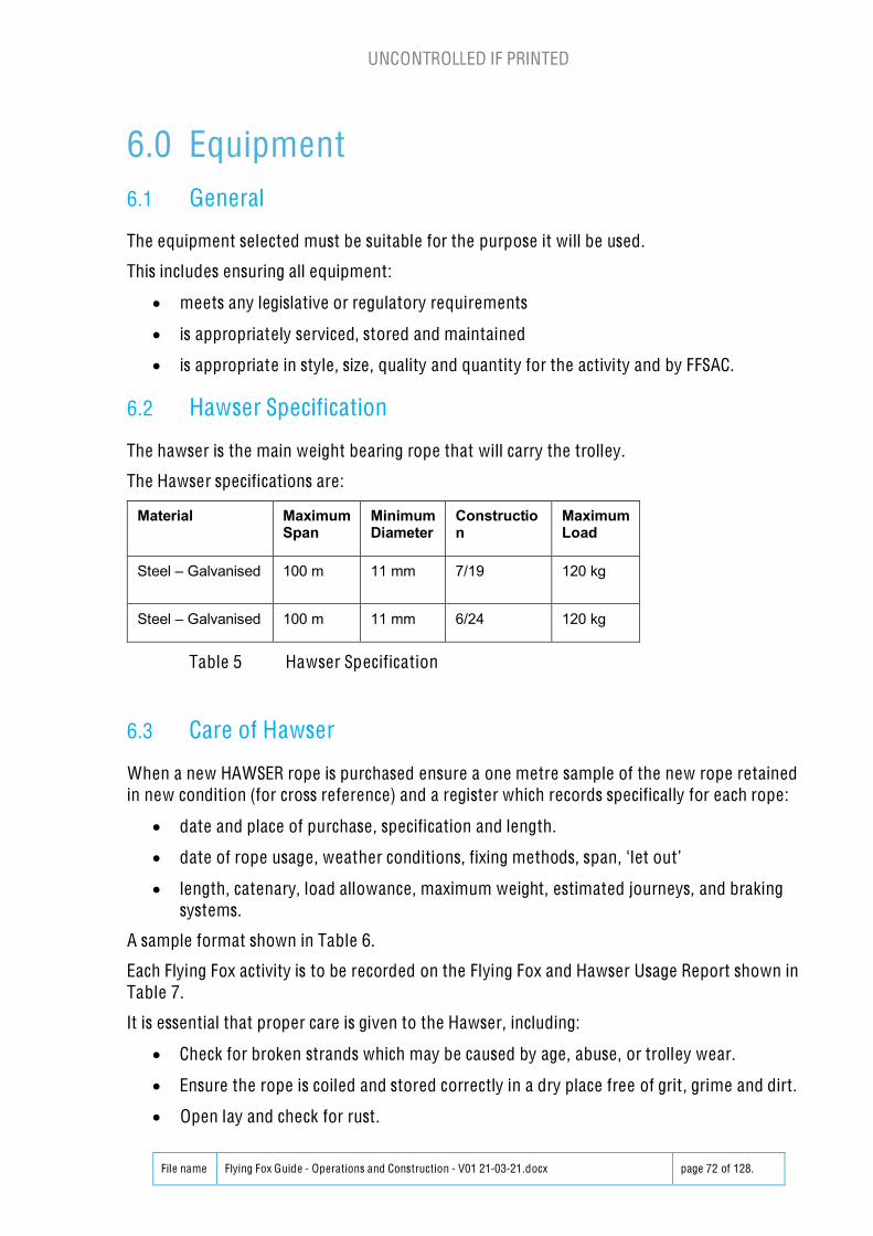
6.1 General 726.2 Hawser Specification 726.3 Care of Hawser 726.4 Hawser End Fixings 736.5 Hawser Damage 756.6 Explanation of Flying Fox & Hawser Usage Report 796.7 Kernmantle Rope Types 806.8 Trolleys 816.9 Droppers 826.10 Pickets and Spars 846.11 Ropes 846.12 Knots & Lashings 856.13 Block and Tackle 926.14 Personal Protection Equipment 92
6.14.1 Harnesses 926.14.2 Helmets 92
6.15 Tools and Accessories 936.16 Gear Inspections 94
6.16.1 General 946.16.2 Wire rope inspection. 946.16.3 Kernmantle Rope Inspection. 976.16.4 Bow Shackles, D shackles and Turn Buckles 996.16.5 Double Base Clamps 996.16.6 Harnesses 100
7.0 Operation and Logistics 1017.1 General 1017.2 Fox Team 102
7.2.1 Leadership 1027.2.2 Roles 102
7.3 Fox Construction 1037.3.1 Fox Set-up 1037.3.2 Dismantling 1077.3.3 Equipment Storage 108
7.4 Communications 1087.4.1 Team Briefing 1087.4.2 Participant Briefing 1087.4.3 Post Review Briefing 1097.4.4 Fox Team Communications 109
7.5 PPE Supervision 1107.6 Participant Movement 1107.7 Emergency Procedures 1107.8 First Aid 1127.9 Inspections 112
7.9.1 Detailed Equipment Inspections 1127.9.2 Operation System Inspection 1127.9.3 Running System Inspection 1137.9.4 Explanation of System Checks 113
8.0 Recognition of Scout Skills and Training 1198.1 General 1198.2 Acquisition of Flying Fox Skills and Recognition 1208.3 NSW recognition of Scouting Skills Flying Fox 1238.4 Upskilling and Maintenance of Flying Fox during transition period 127
9.0 Appendix A – Engineers Report 128
UNCONTROLLED IF PRINTED
File name Flying Fox Guide - Operations and Construction - V01 21-03-21.docx page 4 of 128.
Governance and DisclaimerThe copyright rests with the Scout Associat ion of Australia, NSW Branch.
Subject to the disclaimers herein, permission is given for the Scouting movement toreproduce any portion of this guideline for training and/or safety purposes.
The information contained in this Flying Fox Guide - Operations and Construction aresubject to change from time to time. This manual is intended for use by the ScoutAssociation of Australian for the guidance and training of Scout Association membersqualified operators only and gives no warranty that the information is current, correct orcomplete and is not a definitive statement of procedures for any other purpose .
The Scout Associat ion of Australia, New South Wales Branch advises:
1. This manual form’s part of a competency-based assessment course, and as such itcan accept no liability for use of this manual, other than in the overall course context .
2. This manual is issued under ‘Policy and Rules’ and forms part of and is to be read inconjunction with ‘Policy and Rules’.
3. There are inherent dangers in flying foxes, and unless qualified no member shallattempt to erect or operate a flying fox. Reliance on the data in this manual, in isolation,is not recommended, and no liability is accepted.
To ensure the current version of Flying Fox Scout Association of Australia, NSW BranchFlying Fox Policy and Manual by referring to the copy found inhttps:/ /www.nsw.scouts.com.au/members-services/health-and-safety/whspoliciesforms/
UNCONTROLLED IF PRINTED
File name Flying Fox Guide - Operations and Construction - V01 21-03-21.docx page 5 of 128.
1.0 Introduction1.1 General
Flying fox activities by the Scout Association are part of adventurous activit ies programoffered for its members provides great excitement and adventure for participants.
Flying fox activities involve risks that need be managed by the qualified operators. This isachieved through careful supervision, training, instruction and information. The variousequipment and safety devices for protection against falling from a height and collisions ofequipment designed for this purpose providing a safe adventurous environment.
These risks should, however, be appropriately managed and minimised by the flying foxoperator and team; it should be understood that they cannot be eliminated altogether.Based on a risk assessment, operators should take so far as reasonably practicable measuresto ensure the safety of participants and operators.
This Flying Fox Guide - Operations and Construction (from here referred to as “the Flying FoxGuide”) is intended to summarise Scouts Australia, NSW policy, qualifications, training andguidance for risk management, planning, equipment, operations and logistics.
Category 1 – Scout Approved Scout Flying Fox Activity Construction
This category covers flying foxes built by ‘policy’ qualified persons, greater than 20m and upto a maximum span of 100 metres.
Category 2 – Specialised Scout Flying Fox Activity
This covers flying foxes with spans in excess of 100 metres and/or towers not specifical lycovered by this manual and/or permanent type flying foxes.
This manual, in conjunction with the competency based assessment course, is to assist in thedesign and erection of category 1).
For the construction of flying foxes under category 2), direct reference must be made toFlying Fox State Advisory Committee (“SAC Fox”) as safety considerations may be breachedby applying the standards herein to spans in excess of 100 me tres.
Where a flying fox is proposed that will exceed a span of 100 metres, it will be necessary tosecure a written recommendation from a qualified engineer. If using a tower in excess ofdetails in this manual obtain the appropriate scaffolding high rise work (HRW) license.Submit this to FFSAC for approval and ensuring sufficient time be allowed to obtain suchapproval.
UNCONTROLLED IF PRINTED
File name Flying Fox Guide - Operations and Construction - V01 21-03-21.docx page 6 of 128.
1.2 Applicable Standards
This manual intends to demonstrate compliance to the following standards, Codes andGuidelines as applicable to temporary/mobile structures or permanent installations whereoperated by Scout Association qualified members.
Standard /Codes/ Guidelines Title
AS 2316.2.1-2016 Flying foxes and challenge ropes courses—Construction andsafety requirements (EN 15567-1:2007, MOD)
AS 2316.2.2 - 2016 Flying foxes and challenge ropes courses - Operationrequirements (EN 15567-2:2007, MOD)
AS 4142.1 - 1993 Fibre ropes Care and safe usage
EN12278 - 2007 Mountaineering Equipment Pulleys
EN 12277 Mountaineering equipment, harnesses
ASTM F887 Standard Specifications for Personal Cl imbing Equipment
Outdoor Council ofAustralia
AAAS Australian-Adventure-Activity-Standard-V1.0
Key requirements for preparing and delivering adventureactivit ies.
Outdoor Council ofAustralia
AAAS Challenge-Courses-GPG-v1.0
Guidance for high and low challenge (ropes) courses andadventure/ initiative games.
Outdoor Council ofAustralia
AAAS Core-Good Practice Guide-v1.0
Guidance for common good practice for all adventureactivit ies.
WHS Regulation 2017
NSW Work Health and Safety Act 2011.
NSW Government Code of Practice Safe Design of Structures August 2019
SafeWork NSW - Scaff Safe 2020
UNCONTROLLED IF PRINTED
File name Flying Fox Guide - Operations and Construction - V01 21-03-21.docx page 7 of 128.
1.3 Terms and Definitions
For the purposes of this Flying Fox Operators Manual the following terms and definitionsshall apply.
Term Definition
Advanced Fox Guide (Guide– Construction)
Has with sufficient experience in the operation andconstruction of the Flying Fox to FFSAC and has the Guide –Construction qualification. Refer to Section 8 for details.
Assisted belaying systemBelaying system where the participant is secured by at leastone person
Assistant Guide (FoxGuide-operations)
Has Trained Participant skills but has demonstrated sufficientexperience in the operation of the Flying Fox to FFSAC. Referto Section 8 for details.
BaggingApplicat ion of hessian bagging to the shear leg saddle, anypoint of excessive abrasion, and any green timber anchorage
Catenary Curve formed by a rope, suspended at two points, hangingunder its own weight.
Dead load Weight of the element when unloaded
Dynamic brake Braking system operating automatically to reduce the speedof the participant at the end of run
Dynamic load Load generated by a fall ing participant
Eye An enclosed loop
Flying foxCable support system in which the participant glides undergravity in a sloping direction
FFSAC Flying Fox State Advisory Committee (Scout Association ofAustralia, NSW Branch)
Fox SupervisorPerson supervising the flying fox operations, has Guide-Operations qualification or under the Guide-Operat ionssupervision say for training.
Fox TeamThe team of flying fox personnel, made up of Advanced Guide,Guide, Safe Participant and Trained Participant involved in theflying fox construction and operation.
UNCONTROLLED IF PRINTED
File name Flying Fox Guide - Operations and Construction - V01 21-03-21.docx page 8 of 128.
Term Definition
Guide (Fox Guide -Operations)
Has with sufficient experience in the operation of the FlyingFox to FFSAC and has the Guide – Operations qual ification.Refer to Section 8 for detai ls.
Gated eye An enclosed loop containing a spring-loaded gate.
Hawser The wire rope over the span that carries the trolley and load
Imposed load Load corresponding to maximum weight of a participant
In-line eye
A temporary eye placed in the hawser which negates ‘flowthrough
KernmantleA generic term covering a rope of nylon core and braidedpolyester compliant to AS4142.3
Landing area Area in which a participant finishing the fox run can land
Level 1 supervisionSituation whereby an instructor can physically intervene
File name Flying Fox Guide - Operations and Construction - V01 21-03-21.docx page 9 of 128.
Term Definition
Lizard
A method of attaching a temporary load bearing rope in-linefor tensioning
Locked gate eye A gated eye where the gate locks positively
Maximum fall height Maximum height that a participant can fall
Mobile flying fox Flying fox system that is transportable
Moussing
is a secondary securement method used to secure screw pinfrom rotation or loosening. Annealed iron wire is loopedthrough hole in collar of pin and around adjacent leg ofshackle body with wire ends securely twisted together.
Natural fibre rope Manila or Sisal rope
Operational inspectionInspection, more detailed than routine visual inspection, tocheck the operation and stability of the equipment
OperatorsThe Flying Fox team managing the flying fox activity andoperating the system.
Participants Persons participating in the flying fox activity under theleadership and direction of the operators.
Periodical inspectionVerification, at intervals not exceeding 12 months intended toestablish the overall level of safety of equipment, foundations,and surfaces
Permanent flying fox Flying fox installed for more than 7 days on the same site andprimarily for continual usage throughout the year
Pickets (i.e. star pickets) In ground anchorages
Platform Flat , practically horizontal raised area in which participantscan temporarily stay, before or after the element
RatedThe tested and approved performance characterist ic of acomponent
UNCONTROLLED IF PRINTED
File name Flying Fox Guide - Operations and Construction - V01 21-03-21.docx page 10 of 128.
Term Definition
Regional Advanced FoxGuide
Is the representative for the Scouts NSW Region responsiblefor managing flying fox activities and is recognised by FFSACwith the Advanced Fox Guide qualification
Routine visual check Inspection intended to identify obvious hazards that can resultfrom vandalism, use or weather conditions
Safety LineFlexible or rigid, horizontal, vertical or sloping, continuous ordiscontinuous device used as a protection against fall ing froma height
Safe Participant (FoxAssistant)
Safe Participant may be recruited on the day but are notrecognised as regular team members. Refer to Sect ion 8 fordetails.
Safety system System used either to arrest or cushion a participant's fall
Self-belaying system Belaying system that is operated by the participant him-/herself
Shackle A shackle whose pin performs as a locked gate
Sheave The wheel within a block which is grooved to take a rope.
SlingShort length of wire rope or web material used to attach thehawser to the anchor or tree shear leg to support hawser.
Span The straight-line distance between hawser supports
Spar Timbers used to make the shear legs or other structures
Spotting One or more persons working to catch, hold or give physicalsupport to other participants
Static brake Passive braking system operating automatically
Temporary flying foxFlying fox that has been installed for up to seven (7) days [AS2316.2.1-2016 Cl. 3.3] or periodically longer when approvedby FFSAC
Thimble An insert in an eye that causes less rope stress and abrasion
Trained Participant(previously known asBasic Foxer)
Flying Fox Team member which has basic outdoor Scouttraining, has completed the Flying Fox training course and hasassisted in several Flying Fox activities with the team. Refer toSection 8 for details.
UNCONTROLLED IF PRINTED
File name Flying Fox Guide - Operations and Construction - V01 21-03-21.docx page 11 of 128.
Term Definition
TrolleyThe mechanical system of carriage along the hawser,previously traveller
Turnbuckle Rated device which facilitates fine tuning of the catenarylength
UNCONTROLLED IF PRINTED
File name Flying Fox Guide - Operations and Construction - V01 21-03-21.docx page 12 of 128.
2.0 Flying Fox Policy2.1 Currency
This Scout Association of Australia, NSW Branch Flying Fox Policy is current from the latestissue date noted in the Revision History.
2.2 Review
This manual shall be reviewed by FFSAC at least every 3 years but may be more frequent ifrequired. FFSAC shall be formed from the date of endorsement and be comprised of theexperienced Flying Fox Advanced Guides/Regional Flying Fox Coordinators from all NSWScout regions.
2.3 Purpose
To outl ine the rules of conducting Flying Fox activities by members of Scout Association ofAustralia, NSW Branch.
The Manual document provides guidelines for the construction and compliance of theapparatus, as well as the rules and guidelines for the operation of this apparatus as anactivity.
The Training and Skill Recognition Framework document provides guide-lines for the ongoingskill development and recognition of competencies.
2.4 Philosophy
A Policy for the conduct of Scout activit ies involving Flying Foxes is required for the followingreasons:
x There is inherent risk in these activities.
x Leaders in Scouting need to be aware of risks and apply adequate skills to ensure thatactivities are conducted safely.
2.5 Principles
Control of all activities described in this Policy shall be vested in the Chief Commissioner ofScout Association of Australia, NSW Branch, and his nominated delegates.
A Flying Fox State Advisory Committee (Scout Association of Austra lia , NSW Branch)comprising Delegates from each Region sha ll be established to regularly review theconduct of Flying Fox activities: - FFSAC
The promotion, administration and regulation of Flying Fox activities shall be vested inappropriately qua lif ied Regiona l Coordinator (Flying Fox), appointed by the Regiona lCommissioner or Regiona l Commissioner (Activities).
UNCONTROLLED IF PRINTED
File name Flying Fox Guide - Operations and Construction - V01 21-03-21.docx page 13 of 128.
2.6 Definition
The term " Flying Fox " describes a means of travel along a sloping rope or wire by attachingto it using a free moving pully and being propelled by gravity (R1 AAAS Challenge-Courses-GPG-v1.0 definition).
2.7 Scope
This Policy relates to all Category 1 – qualified Scout Flying Fox activities and associatedconstruction and operation.
Inclusions to this policy:
All Scout Association of Australia, NSW Branch Flying Fox activities and associatedconstruction of spans greater than 20 metres. Flying Fox operation and construction 20m orless are covered by Scouts Australia PRO42 Challenge ropes policy.
Exclusions to this policy:
x Tyrolean and traversing techniques where participants progress under their own power(or teamwork)
x Pioneering structures for flying fox under 20 metres and pioneering type constructedusing timber spars and rope (pioneering structures for flying fox under Scout pioneeringconstruction guidelines).
x Commercially conducted activit ies, run by persons or organisations outside the ScoutAssociation.
x Any specific insurance requirements for publicly run Flying Fox activities.
Before participation in any commercially conducted Flying Fox activity, the policy onProhibited Activities, and the guidelines for participation in Commercially Run Activities,should be considered.
2.8 Operation
The Flying Fox State Advisory Committee (Scout Association of Australia, NSW Branch)(“SAC Fox”) is to:
x Regularly review this Policy, Schedules to the Policy, and other documentation asapplicable
x Advise State executive on technical matters relating to this Policy
x Form sub-committees as required to assist with technical standards, safety and training
x Determine and specify minimum standards for all equipment used for these activities
x Provide endorsement of members of Scout Association of Australia, NSW Branch whohave the required recognized skill levels to enable them to operate a Flying Fox at a StateActivity Centre following local induction.
x Maintain records of qualifications issued and appointments made by the SAC Fox.
The Regional Coordinator (Flying Fox) is to
x Promote, administer and regulate Flying Fox activities within their Region
UNCONTROLLED IF PRINTED
File name Flying Fox Guide - Operations and Construction - V01 21-03-21.docx page 14 of 128.
x Authorise the conduct of Flying Fox activities within the Region
x Maintain regional Flying Fox records of training, completion of workbooks andrecommended appointments made within the Region
x Cancel or suspend any qualification pending Region and SAC Fox review if practices areconducted in an unsafe manner or contrary to this Policy
x Recommend to the Regional Commissioner the suspension of any Leader's appointmentif practices seriously contravene this Policy or other Scout Code of Practice.
2.9 Authors / Officers
This Scout Association of Australia, NSW Branch Flying Fox Policy and Manual was drafted bymembers of the Flying Fox Review Committee (Scout Association of Australia, NSW Branch),April-August 2020.
The review committee was formed at the behest of the Chief Commissioner’s Council andthe Chief Commissioner of NSW following attention to a series of incidents on commercialFlying Foxes.
Members were selected on merit within a set of criteria. The Review Committee wasconvened by the Assistant Chief Commissioner Activities, Bases and Fellowships, andoverseen by the Deputy Chief Commissioner Activities and Training, and State Office SafetyOfficer.
2.10 Flying Fox State Advisory Committee
Role: The purpose of this committee is to utilise the experience of Flying Fox practitioners tomonitor changes to applicable standards, review and revise SOP accordingly and provideguidance to Scouts NSW on all matters relating to policy for the operations related to FlyingFox activities undertaken as part of Scouts NSW activities.
Representat ion: It is recognising that FFSAC members are not professionals in this field butvolunteers with extensive practical experience in the operation and construction of FlyingFox activities for Scouts. Where possible this committee is to have representat ion from asmany Scout NSW Regions as possible to ensure sharing of experience and to promote usingthe latest practises in all Regions.
Procedures:
x The FFSAC should meeting at 6-12 monthly intervals, or more regularly if any actionsrequire.
x FFSAC meetings should, as a minimum, include the following agenda items:
o Review of any WH&S incidents reported (Check Scouts NSW register plus anycommercial Flying Fox incidents publicly reported)
o Review of recent activities undertaken, any lessons learnt
o Review any areas within the “Flying Fox Guide - Operations and Construction”requiring amendment
o Review of training requirements
o Review of future planned Flying Fox activities
UNCONTROLLED IF PRINTED
File name Flying Fox Guide - Operations and Construction - V01 21-03-21.docx page 15 of 128.
o Next Meet ing date
x Minutes/Notes are to be made each meeting and circulated to all Regions, note notjust to Regions represented.
2.11 Authority
Scout Association of Australia, NSW Branch.
2.12 References and Implementation
This statement provides the context for the:
x Flying Fox Guide (Scout Association of Australia, NSW Branch) Version: 01 2021 and
x FF Training and Qualification Framework v2:2020_5_30.
These rules and guidelines take effect from the date of endorsement from NSW Scouts, ofthis Flying Fox Guide.
UNCONTROLLED IF PRINTED
File name Flying Fox Guide - Operations and Construction - V01 21-03-21.docx page 16 of 128.
3.0 Management of Risk3.1 General
For over 100 years, Scouting has been an important and successful part of the Australiancommunity providing non-formal educational and recreational programs that help youngpeople to develop emotionally, intellectually, socially spiritually and physically. Awarenessof risk has always been a key focus for Scouts Australia in its delivery of programs for youngpeople.
The risk management procedures for Flying Fox activities are to be compliant with ScoutsAustralia NSW National Risk Management guidelines, refer Scouts NSW PRO18 WHS RiskManagement https:/ /www.nsw.scouts.com.au/wp-content/ uploads/2020/11/PRO-18-WHS-Risk-Management-v-2.0-signed.pdf (or check Scout Association of Australia, NSW Branchwebsite for direction if link is inoperable).
Risk management is critical for Scouts offering Flying Fox activities in a safe environment toall participants, including operators. The management of risk and the development of safetysystems must focus on all stages of the design, planning, preparation and delivery of theflying fox activities.
Before any Fox is constructed, during its construction, during its operation, duringdismantling and transportation, leaders must be aware of any safety issues. Prior toconstruction, at least one site visit needs to be carried out to determine any safety issuesspecific to the site. The observation will be recorded, along with what will be done to reduceor remove that risk.
A competent person wil l inspect the structure after its construction and prior to itsoperation. Operational checks will also be performed at regular intervals to check formovement or other changes.
3.2 Management of Risk Overview
The Scouts Australia Risk Management System has been developed in conjunction withScouts Australia NSW National Risk Management guidelines and in accordance with AS/NZSISO 31000:2009. It is designed to give assurance that, despite any risk that may be inherentin our activit ies, the levels of residual risk are acceptable in that effective controls are inplace to minimise the potential for harm or loss to Scouts Australia or to its stakeholders.Importantly, the system also provides a planning basis from which to manage potential gainsfor the organisat ion through the management of risk.
3.3 Key Flying Fox Risks
It is essential that all risks are identified. Most activities and initiatives of Scouts Australia’swill be comparatively straightforward, comprising no more than routine ‘core-activities’.Hence, in this Flying Fox Guide we highlight risks specific and key to the safe operation of aflying fox typically. This means that persons responsible for leading the flying fox activity willneed to assess their specific activity in detail to see if there are any additional risks that canbe identified.
Based on investigation of key past safety risks related to flying foxes are the following:
UNCONTROLLED IF PRINTED
File name Flying Fox Guide - Operations and Construction - V01 21-03-21.docx page 17 of 128.
Equipment:
Equipment is suitable for purpose and being used within the manufacturers’recommendations
Equipment is inspected by experienced operators on the Scout Association of Australia, NSWBranch Flying Fox team prior to use and is in GOOD condition.
Construction Practices:
Construction practices must be in accordance with the guidelines set out in this OperatingManual
Avoid any single points of failure which can result in persons falling
Any use of trees or other natural features shall be suitable for the forces imposed with alarge safety margin
Construction set up must be planned to provide fall protection
PPE must be used during set up, operation and dismantling to minimise risk of injuryLoad Rating:
All equipment must be used within the manufacturers installation method andstamped/published load rating.
Hawser Termination:
The load tension support for the hawser must be in accordance with the guidelines set out inthis Scout Association of Australia, NSW Branch Flying Fox Policy and Manual
Hawser terminations must be regularly inspected during flying fox operation to confirm nomovement or slippage occurs
Inspections:
The whole operating system/construction must be regularly checked during the operation ofthe flying fox
The inspections must be undertaken by experienced operators on the Scout Associat ion ofAustralia, NSW Branch Flying Fox team.
Communications:
Ensure all participants can communicate during operation so as flying fox runs are onlyinitiated when safe to do so.
Ensure participants are briefed and understand the use of the flying fox and any actions notpermitted
3.4 Monitor, Review and Communication
Procedures and networks for monitoring, reviewing, and communication about riskmanagement must be established as part of the overall risk management framework. ScoutAssociation of Australia, NSW Branch have established a Flying Fox State AdvisoryCommittee (Scout Association of Australia, NSW Branch) and this group should reviewannually any accidents, injuries and near misses to ensure safety risk management iscontinually improved.
UNCONTROLLED IF PRINTED
File name Flying Fox Guide - Operations and Construction - V01 21-03-21.docx page 18 of 128.
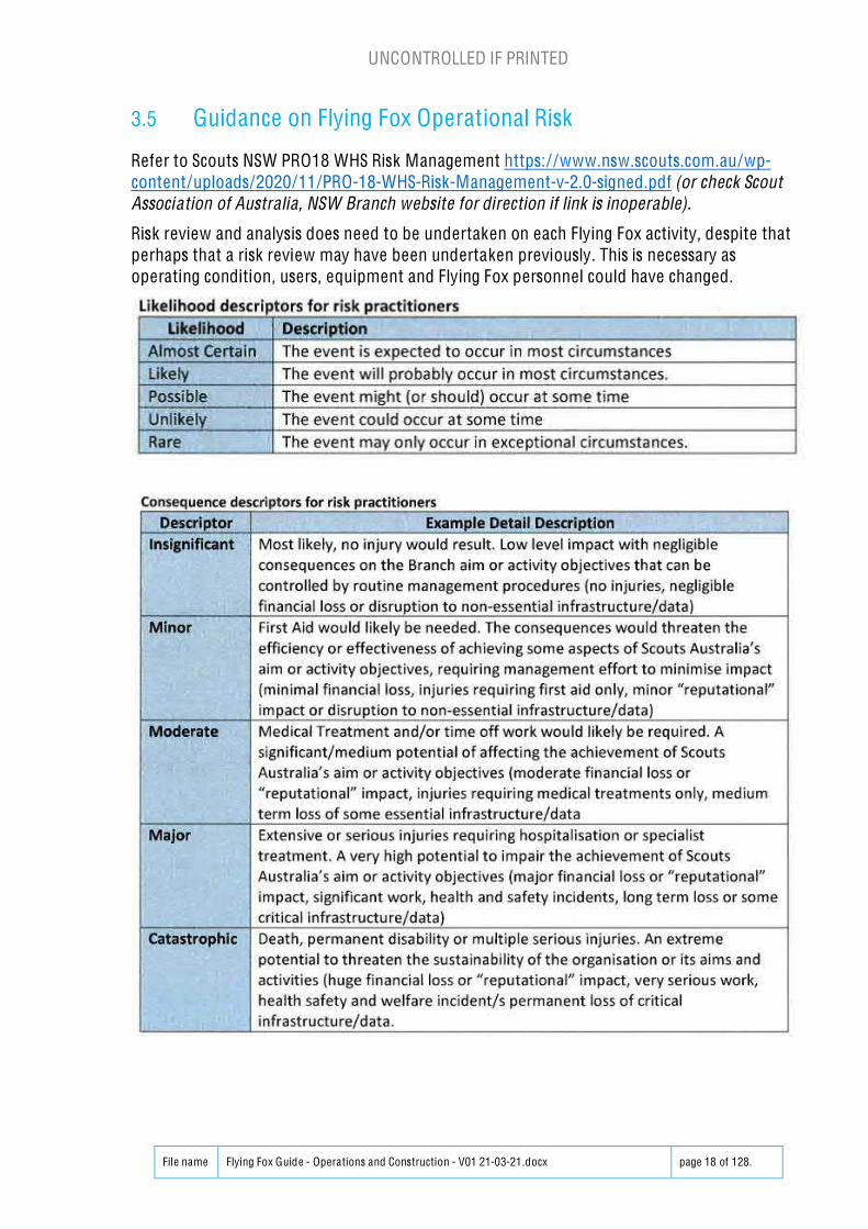
3.5 Guidance on Flying Fox Operat ional Risk
Refer to Scouts NSW PRO18 WHS Risk Management https:/ /www.nsw.scouts.com.au/wp-content/uploads/2020/11/PRO-18-WHS-Risk-Management-v-2.0-signed.pdf (or check ScoutAssociation of Australia, NSW Branch website for direction if link is inoperable).
Risk review and analysis does need to be undertaken on each Flying Fox activity, despite thatperhaps that a risk review may have been undertaken previously. This is necessary asoperating condition, users, equipment and Flying Fox personnel could have changed.
UNCONTROLLED IF PRINTED
File name Flying Fox Guide - Operations and Construction - V01 21-03-21.docx page 19 of 128.
UNCONTROLLED IF PRINTED
File name Flying Fox Guide - Operations and Construction - V01 21-03-21.docx page 20 of 128.
Note that the example below only highlights specific risks which may impact the Flying Fox and it does not include the usual slip, trips and fall risks which maybe encountered on Scout camps or similar activities.
BASE RISK ASSESSMENT
Identify the hazards a Assess the risk Mitigate the risk Re-assess the risk Responsibility
Activity (Task /Location) List of Hazards / Risks
Like
lihoo
d
Con
sequ
ence
Rat
ing Current Controls
Control Measures Required
AdditionalControl Means
Res
idua
lra
ting Person
Storage
Storage
- Water damage
- Rodent damage
- Unauthorisedequipment use
- Chemicaldamage/corrosion
Pos
sibl
e
Mod
erat
e
Sign
ifica
nt
Equipment stored fullyenclosed in trailers and/orstored in halls locked to preventunauthorised access.
Refer Section 7.3.3Equipment Storage
Mod
erat
e
RegionalAdvancedFox Guide
Transport
Transport
- Heavy load
- Unsecure lead leadingto impact damage tobreakage
- Driver fatigue
Pos
sibl
e
Mod
erat
e
Sign
ifica
ntFox gear is transported either indedicated trailers or suitabletrailers for the load to betransported.
PR020 Vehicle and DriverSafety policy
Transportation plannedso as not to call forlong, early or late travelor multiple drivers areavailable. M
oder
ate
RegionalAdvancedFox Guide
UNCONTROLLED IF PRINTED
File name Flying Fox Guide - Operations and Construction - V01 21-03-21.docx page 21 of 128.
Identify the hazards a Assess the risk Mitigate the risk Re-assess the risk Responsibility
Activity (Task /Location) List of Hazards / Risks
Like
lihoo
d
Con
sequ
ence
Rat
ing Current Controls
Control Measures Required
AdditionalControl Means
Res
idua
lra
ting Person
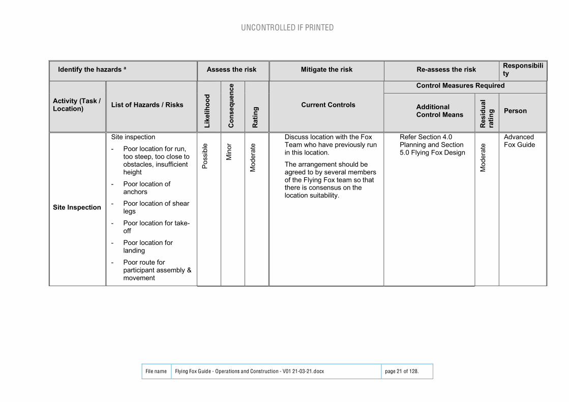
Site Inspection
Site inspection
- Poor location for run,too steep, too close toobstacles, insufficientheight
- Poor location ofanchors
- Poor location of shearlegs
- Poor location for take-off
- Poor location forlanding
- Poor route forparticipant assembly &movement
Pos
sibl
e
Min
or
Mod
erat
e
Discuss location with the FoxTeam who have previously runin this location.
The arrangement should beagreed to by several membersof the Flying Fox team so thatthere is consensus on thelocation suitability.
Refer Section 4.0Planning and Section5.0 Flying Fox Design
Mod
erat
e
AdvancedFox Guide
UNCONTROLLED IF PRINTED
File name Flying Fox Guide - Operations and Construction - V01 21-03-21.docx page 22 of 128.
Identify the hazards a Assess the risk Mitigate the risk Re-assess the risk Responsibility
Activity (Task /Location) List of Hazards / Risks
Like
lihoo
d
Con
sequ
ence
Rat
ing Current Controls
Control Measures Required
AdditionalControl Means
Res
idua
lra
ting Person
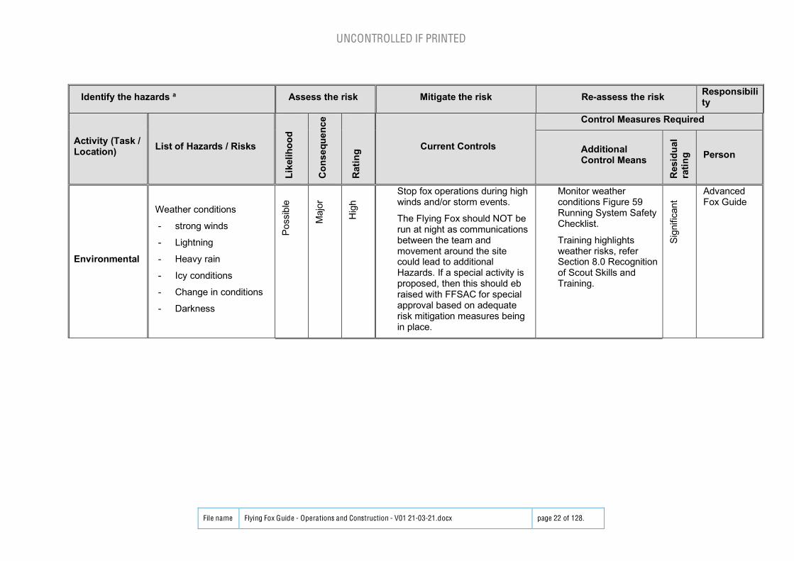
Environmental
Weather conditions
- strong winds
- Lightning
- Heavy rain
- Icy conditions
- Change in conditions
- Darkness
Pos
sibl
e
Maj
or
Hig
h
Stop fox operations during highwinds and/or storm events.
The Flying Fox should NOT berun at night as communicationsbetween the team andmovement around the sitecould lead to additionalHazards. If a special activity isproposed, then this should ebraised with FFSAC for specialapproval based on adequaterisk mitigation measures beingin place.
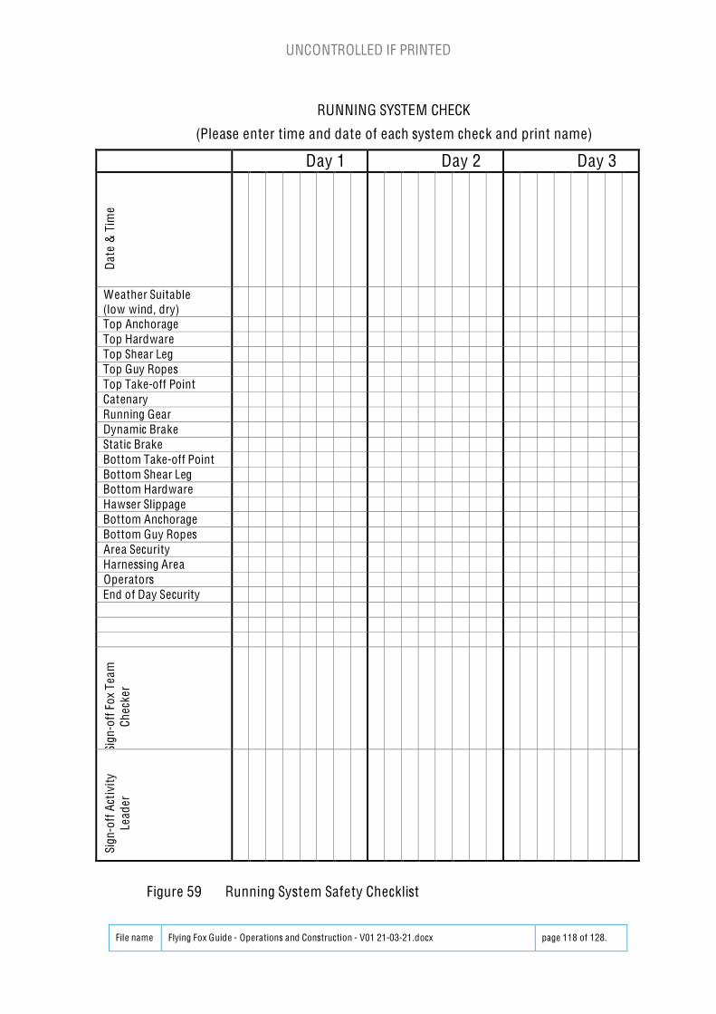
Monitor weatherconditions Figure 59Running System SafetyChecklist.
Training highlightsweather risks, referSection 8.0 Recognitionof Scout Skills andTraining.
Sign
ifica
nt
AdvancedFox Guide
UNCONTROLLED IF PRINTED
File name Flying Fox Guide - Operations and Construction - V01 21-03-21.docx page 23 of 128.
Identify the hazards a Assess the risk Mitigate the risk Re-assess the risk Responsibility
Activity (Task /Location) List of Hazards / Risks
Like
lihoo
d
Con
sequ
ence
Rat
ing Current Controls
Control Measures Required
AdditionalControl Means
Res
idua
lra
ting Person
Construction
Construction
- Inadequate space forgear set-up
- Movement of heavyequip top/bottom oftun
- Fall from height
- Impact from fallingobjects
- Star picket or pegsdamaging electrical ofother undergroundservices
Pos
sibl
e
Mod
erat
e
Sig
nific
ant
Proper PPE for fall/impactprotection.
Discuss location with the FoxTeam who have previously setup in this location to minimisemanual lifting.
Discuss with property caretaker or authorities to ensure nounderground services in thevicinity. If any risk, undertakedetailed services search.
Belay team during all work atheight, establish belay pointsearly during construction.
No unauthorised access in theconstruction area apart fromthe fox team.
Ensure star pickets have capsand any other sharp objects areprotected from causing injury.
Refer Section 7.3 FoxConstruction.
Refer Appendix A –Engineers Report.
Mod
erat
e
AdvancedFox Guide
UNCONTROLLED IF PRINTED
File name Flying Fox Guide - Operations and Construction - V01 21-03-21.docx page 24 of 128.
Identify the hazards a Assess the risk Mitigate the risk Re-assess the risk Responsibility
Activity (Task /Location) List of Hazards / Risks
Like
lihoo
d
Con
sequ
ence
Rat
ing Current Controls
Control Measures Required
AdditionalControl Means
Res
idua
lra
ting Person
Operations
- Movement
- Collision of persontravelling down the foxand people walkingacross the path of theflying fox run
- Route from assemblyarea up to take offzone too steep, closeto cliffs or dead trees
-P
ossi
ble
Min
or
Mod
erat
e
Mark out run zone, providehazard tape marking.
Run in existing locations withestablished routes.
Guide / Activity Leaders toparticipant ratios dependent onactivity in accordance with thisFlying Fox Manual
Refer Section 7.3 FoxConstruction.
Refer Section 7.4.4Participant Briefing.
Refer Section 7.6Participant movement
Mod
erat
e
AdvancedFox Guide
Operations
- GeneralConstruction
- Failure of shear leg/s
- Failure of brakecausing impact tobottom shear leg
Pos
sibl
e
Mod
erat
e
Sign
ifica
nt
Experienced Fox teamconstructing the flying fox.
Discuss with Fox Team whohave previously set up in thislocation to get feedback of pastfox construction on this site.
Inspection of components(Detailed inspection min. every3 years, refer Section 7.9)
Rigging in accordance with thisFlying Fox Manual
Checking participant prior torun for loose hair/loose clothing
Refer Section 6.0Equipment.
AdvancedFox Guide
UNCONTROLLED IF PRINTED
File name Flying Fox Guide - Operations and Construction - V01 21-03-21.docx page 25 of 128.
Identify the hazards a Assess the risk Mitigate the risk Re-assess the risk Responsibility
Activity (Task /Location) List of Hazards / Risks
Like
lihoo
d
Con
sequ
ence
Rat
ing Current Controls
Control Measures Required
AdditionalControl Means
Res
idua
lra
ting Person
Operations
- HawserFailure
- Failure of hawseranchor/s
- Slippage of inlineeye/s or rope clamps
- Failure of Hawserrope
Pos
sibl
e
Cat
astro
phic
Hig
h
Care of the Hawser.
Experienced fox teaminstallation anchors.
Hawser rope double clampsused.
Experienced team carrying outinspections.
Refer Section 7.3 FoxConstruction.
Refer Section 6.16.2Wire rope inspection
Refer Section 7.9.3Explanation of SystemChecks
Refer Appendix A –Engineers Report.
Sign
ifica
nt
AdvancedFox Guide
Operations
- Take Off
- Fall from top take-offplatform
- Letting participant gobefore team ready toreceive possibleimpact with persons orequipment
Pos
sibl
e
Mod
erat
e
Sign
ifica
nt
Top fox team member fastenssafety line on scout and onlyunfastens when secure onrunning gear drop line.
Fox operators to be belayed.
Communications protocolbetween landing team and takeof team
Refer Section 7.2.2 FoxTeam Roles
Refer Section 7.3.1 FoxSet-up
Refer Section 7.4.4 FoxTeam Communications
Mod
erat
e
AdvancedFox Guide
UNCONTROLLED IF PRINTED
File name Flying Fox Guide - Operations and Construction - V01 21-03-21.docx page 26 of 128.
Identify the hazards a Assess the risk Mitigate the risk Re-assess the risk Responsibility
Activity (Task /Location) List of Hazards / Risks
Like
lihoo
d
Con
sequ
ence
Rat
ing Current Controls
Control Measures Required
AdditionalControl Means
Res
idua
lra
ting Person
Operations
- EquipmentLanding
- Hawser too lowleading to impact onground
- Equipment in path oftravel leading toimpact
Pos
sibl
e
Mod
erat
e
Sign
ifica
nt
Experienced fox team settinghawser tension.
Experienced team carrying outinspections.
Communications protocolbetween landing team and takeof team
Refer Section 7.4.1Hawser Tensioning
Refer Section 7.9.3Explanation of SystemChecks
Refer Section 7.4.4 FoxTeam Communications
Mod
erat
e
AdvancedFox Guide
Operations
- PPE Fitting
- Incorrect fitting PPEleading to fall
- Failure of harnessleading to fall
Pos
sibl
e
Mod
erat
e
Sign
ifica
nt
Experienced team carrying outfinal checks of PPE fitting.
Second check off PPE just priorto take-off
Refer Section 6.14Personal ProtectionEquipment
Refer Section 7.5 PPESupervision
Refer Section 7.2.2 FoxTeam Roles
Mod
erat
e
Fox Guide
Operations
- RunInspections
- Operations leading toequipment slippageleading to hawserfalling
- Operations leading toequipment slippageleading to brakeineffectiveness andimpact
Pos
sibl
e
Mod
erat
e
Sign
ifica
nt
Experienced team carrying outinspections.
Refer Section 6.16Gear Inspection,including havingmultiple Fox Teammembers carry out theinspection and not justone person
Mod
erat
e
AdvancedFox Guide/Fox Guide
UNCONTROLLED IF PRINTED
File name Flying Fox Guide - Operations and Construction - V01 21-03-21.docx page 27 of 128.
Identify the hazards a Assess the risk Mitigate the risk Re-assess the risk Responsibility
Activity (Task /Location) List of Hazards / Risks
Like
lihoo
d
Con
sequ
ence
Rat
ing Current Controls
Control Measures Required
AdditionalControl Means
Res
idua
lra
ting Person
Short breakfrom operation
- Unsupervised foxusage and possibleincorrect usageleading to fall orimpact P
ossi
ble
Mod
erat
e
Sig
nific
ant
Flying fox access blocked off
Trolley removed
At least one from fox team leftto supervise
Refer Section 7.2 FoxTeam
Mod
erat
e
Fox Guide
Overnight outof operations
- Flying fox used whenFox Team supervisionis not present, risk offall from height orimpact
Pos
sibl
e
Mod
erat
e
Sig
nific
ant
Flying Fox are de-rigged at endof day
Access to Flying Fox isrestricted between scheduledactivity sessions.
Ladder is locked.
Warning signs placed at Flyingfox
Refer Section 7.2 FoxTeam
Mod
erat
e
AdvancedFox Guide
De-construction
Construction
- Inadequate space forgear pack-up
- Movement of heavyequip top/bottom oftun
- Fall from height
- Impact from fallingobjects
Pos
sibl
e
Mod
erat
e
Sig
nific
ant
Experienced Fox teamdismantling the flying fox.
Discuss with Fox Team whohave previously set up in thislocation to get feedback of pastfox dismantling on this site.
Refer Section 7.3.2Dismantling
Mod
erat
e
AdvancedFox Guide
Table 1 SAMPLE Flying Fox Risk Assessment Form
UNCONTROLLED IF PRINTED
File name Flying Fox Guide - Operations and Construction - V01 21-03-21.docx page 28 of 128.
3.6 Incident Reporting
Note: All flying fox incidents are reportable.
Incident reporting is in line with Scout Association of Australia, NSW Branch WHSprocedures, specifically via the Scouts NSW WHS Incident Report Form.
In addition, the SAC Fox require all incidents, near misses, and novel situations requiringresponse to be reported so that improvements can be made to Fox processes.
AS 3533 requires that any accident occurring on a flying fox is ‘reportable’ . Wherenecessary, this manual will be updated with necessary information to ensure that suchaccidents do not reoccur.
It is mandatory that there be an emergency plan in force, and known by all operators, priorto the running of the flying fox, which will cover all likely ‘accidents’ that may occur. This isthe operator’s responsibility.
As a First Aider must be present when a flying fox is run, we wi ll assume that generalemergency procedures are known.
Terms to consider:
Hazard: something that could hurt you, could cost money, cause damage, loss ofequipment, injury, loss of earnings etc.
Risk: the chances of the hazard impacting on the activity: probabil ity and potential severity.
Incident: Sometimes known as an accident. An event or chain of events, which has, or couldhave caused injury, Illness, financial loss or reputational loss to people or assets. Incidentsinclude: injury, illness and near miss.
Near M iss: An event which, although it did not result in personal injury/disease or damageto people, property or the environment, it had the potential to do so.
Accident: An event which has resulted in bodily injury or property damage.
UNCONTROLLED IF PRINTED
File name Flying Fox Guide - Operations and Construction - V01 21-03-21.docx page 29 of 128.
4.0 Planning4.1 General
Whether preparing for one, or a series of activit ies, the management, design and delivery ofFlying Fox activit ies requires good planning. Planning allows the Fox Team to
To meet our objectives to provide an enjoyable experience safely; and
Achieve the personal goals for activity leaders and participant.
There must be a process in place for the development of an activity plans for each activitythat suit the context and purpose.
4.2 Participants
Differing people will require different provisions in line with age/ physical ability/ fitness/confidence and other considerations to ensure their safe enjoyment of a Flying Fox activity.
Joey and Cub Scouts wi ll need closer assistance regarding harness fitment and attaching anddetaching from the Fox. Follow Scout Guidelines in relation to physical assistance and YouthProtection. Less assistance may be required for Scouts and older age groups.
Another consideration would be for older non- Scouts who may need as much assistance asa Joey Scout. Additional support and instruction may be required for the take-off andlanding zones, and access routes, especially with a dual runway in use.
4.3 Pre-Activity Checks
The following Pre-Activity Checks should be undertaken:
x If the Flying Fox activity is part of a larger activity, ensure the organisation group isaware of the fox spatial requirements, participants/parents have been notified andgiven consent to participate in the Flying Fox and any necessary approvals have beenobtained.
x If the Flying Fox activity is part of a larger activity, ensure the first aid and incidentreporting structure is understood.
x Where the site is new for the flying fox or has been a long time since the last Foxactivity there, then a site visit and planned construction should be undertaken priorto the activity to be sure it can be safely run and that no recent environmentalchanges could compromise that safety.
x Check the Weather forecast, including for set up and pack up.
UNCONTROLLED IF PRINTED
File name Flying Fox Guide - Operations and Construction - V01 21-03-21.docx page 30 of 128.
4.4 Site Arrangement
It is preferable to use only those sites, trees, anchors known well to the team. A walkthrough the site / potential site a week or so prior to the ‘planned’ activity helps reduce thepossibility that the site will not be suitable due to changed conditions or lack ofunderstanding of the activity requirements. At the preparatory visit, all aspects of safe Foxoperations, from working at heights to exit from landing zone, need to be considered.
The possibility of finding two identical or similar sites is remote, and it is this large variety ofsites which makes the formulation of a standard policy difficult.
Some general rules are:
x Use the lay of the land to your best advantage.
x Shear Legs can be trees or structures, pioneering type or fabricated type.
x Anchorages may be natural features, i.e. tree trunks or constructed anchorages suchas log and picket , triple picket and dead man anchors.
The following figures indicate some options:
Figure 1 Tree Shear to Tree Shear Legs with Fall
UNCONTROLLED IF PRINTED
File name Flying Fox Guide - Operations and Construction - V01 21-03-21.docx page 31 of 128.
Figure 2 Upper Tree Shear Leg & Picket Anchors and Lower Shear LegStructure with Tree Anchor
Figure 3 Upper and Lower Tree Shear Legs with Log & Picket Anchors
But we must look at some basic criteria so we can assess if the chosen method is secure,given the potential large loading stress that applies to flying foxes.
For the purpose of developing our ‘model’ we will assume a tree to shear leg configuration.Each step with its rules is interchangeable for another step, provided the rules remainmatched to each step.
The location will determine your span length which wil l not exceed 100 metres.
Your options are then basically one of two designs:
Turnbuckle and Shackles ‘in line’
The hawser carrying capacity terminates at an eye with a shackle connection to full loadrated turnbuckle/s connected to the hawser ‘in line’ and the bottom anchor.
Block and tackle ‘lizard’
UNCONTROLLED IF PRINTED
File name Flying Fox Guide - Operations and Construction - V01 21-03-21.docx page 32 of 128.
The hawser runs from anchorage to anchorage, and the block and tackle is lizarded to thehawser. This in effect gives a double roping over the block and tackle length. This can onlybe used for ra ising / lowering the hawser and at no time must the human load be carrieddirectly by a lizard line, apart for exceptiona l circumstances where it has been set up aspart of the emergency rescue plan but then it should be tested with a dead load for thatpurpose.
Both the above methods can lead to hawser damage if correct care is not taken with what isbeing done.
4.5 Slope of Runway
The tighter the rope the faster the run, but the greater the tension and associated forces onthe hawser.
Subject to the provision of appropriate braking, the maximum average angle of descentshould not exceed 45 degrees. (This requires that span height must be equal to or less thanspan width).
Figure 5 Maximum Hawser Slope
By slackening the rope, the end tangent angle of descent may increase, so at any given pointthe end tangent angle of descent should not exceed 65 degrees.
UNCONTROLLED IF PRINTED
File name Flying Fox Guide - Operations and Construction - V01 21-03-21.docx page 33 of 128.
Figure 6 Maximum Take-off Angle
4.6 Slope of Runway - Safety Considerations
The design criteria in Figure 5 and F igure 6 are to be considered maximum and in isolat ion.These are maximums and must be considered in relation to the location.
In most instances, if these were combined on a more conventional location, these couldlead to serious injury as the high degree of ascent combined with a slack rope could result ina catenary at or near conclusion of the run that would drive the passenger into the ground.Always remember that the catenary wil l tend to triangulate at the ends of the span.
The conventional recommendations for flying fox rope alignment are that the horizontalangle of the span line does not exceed 10 degrees and that the unloaded rope angle doesnot exceed 15 degrees. 10 degrees equates to a 1 in 5.5 fall, while 15 degrees equates to a 1in 3.5 fall .
Figure 7 Hawser Speed
Whilst exceeding these parameters may increase the ‘thrill’, all care must be taken toensure the overall safety of the passenger.
The maximum effective speed (velocity) is 11 km / h average (3.055 m /sec.) in accordanceto AS2555.
UNCONTROLLED IF PRINTED
File name Flying Fox Guide - Operations and Construction - V01 21-03-21.docx page 34 of 128.
5.0 Flying Fox Design5.1 Anchors
Init ial and timely inspection will afford the best possible anchors. If in doubt, ‘don’t’ .
Note in genera l the minimum SWL limit adopted by Scout Association of Austra lia , NSWBranch is a minimum of 4T SWL for the Hawser and a ll associated in line fixtures,fastenings and anchors.
Note: Due to the diversity of condit ions, anchorages are potentially the weakest link in thedesign. Therefore, during hawser tensioning, design testing, and full running, continuousinspection must be directed to all anchorages.
Any signs of movement in the soil around the pickets or other anchorages, or persistentloosening during operation, implying movement of anchorages, signify a weakness andhence a ll operations must be discontinued.
Low strength soils, such as swamps and mud flats, are to be avoided.
At the first indicat ion of a problem, stop use of the fox, and correct the fault . If it cannot beremedied, discontinue the entire activity.
5.1.1 Tree Anchors
The tree should be a mature tree , free from termites, living, well rooted (not on rock shelf),be of a type that is ‘good burning’ (avoid banksia etc), and be of a minimum 600 mmdiameter (2 fee t) 1200-1500mm above its base . Hug the tree and if more than fingersmeet, in the case of an adult, find a bigger tree.
Securing should be as close to the base as is practica l, but where securing is attempted at aheight exceeding 2 metres above the ground, safety lines must be used to secure the peopleinvolved. Where the tree is at a cliff edge, or other safety concerns apply, guying the tree isconsidered essential.
Where securing to a tree fork, select a suitably safe fork, and if necessary, treat it as a shearleg, and secure the rope lower down the tree to the trunk or another suitable limb, or toanother anchorage. Alternatively, square lash a spar above the fork, and draw the hawserover the spar. If the fork is used directly, it should be bagged to avoid damage to the tree,and to allow easy hawser ‘slip’ as tension is applied.
UNCONTROLLED IF PRINTED
File name Flying Fox Guide - Operations and Construction - V01 21-03-21.docx page 35 of 128.
Figure 8 Sling Anchor Using Tree
The tree must be ‘bagged’ if using wire slings. A sling with thimble eyes at each end can becentred around the tree. The hawser (with thimble eye end) is attached to the sling using arated moussed shackle.
The sling and hawser must be either steel or equivalent rated webbing sling.
To avoid undue stress on the sling by installing it in a chocked configuration which wil l de-rate the SWL. The sling should lay parallel to the hawser exit lay in a loop configuration asillustrated in Figure 9.
The angle between the sling tails should never exceed 120 degrees, as beyond this theeffective strength of the Sling is below the rating of the hawser. As 90 degrees is easier tovisualise, this should be the targeted minimum induced angle, refer Figure 9.
UNCONTROLLED IF PRINTED
File name Flying Fox Guide - Operations and Construction - V01 21-03-21.docx page 36 of 128.
Tree or Anchor point
120o
HawserFig 23
Figure 9 Sling Loop Configuration on Tree
The idea l sling arrangement above is in a basket configuration which is therecommended method as 3T slings will support a load up to 5.1T. Note thatincreasing the angle of the sling to the hawser greatly reduces the sling rating.
Note that choking a sling greatly reduces the rating, refer to the Figure 10 deratingchart.
Figure 10 Flat Webbing & Round Sling Working Load Limit
(EnergySafe Victoria for slings manufactured to AS1353.1, AS1353.2 and AS4497.1)
UNCONTROLLED IF PRINTED
File name Flying Fox Guide - Operations and Construction - V01 21-03-21.docx page 37 of 128.
Figure 11 Wire Rope Sling Working Load Limit
(EnergySafe Victoria for slings manufactured to AS1666)
The tail of the hawser is then passed over the shear legs (not yet erected), and thepositioning of the anchorage is then determined. The distance from the anchorage to theshear leg base shall be twice the distance from the shear leg base to the saddle.
Fig 9cH
2H
Figure 12 Attachment to Tree
5.1.2 Picketing
There is a large variation in soil types in Australia, ranging from rock through clay and sand,and for this reason the picketing method selected must best suit the soil type, and allow formaximum safety.
‘Traditional’ soil types consist of a ‘topsoil’ which on average is to a depth of 200 mm. Thesub soil, may be clay etc, is what gives the picket its ‘holding power’, and it is where thelevels meet that we will refer to as the ‘PIVOT POINT’. (where it bends when overstressed),refer to Figure 13.
UNCONTROLLED IF PRINTED
File name Flying Fox Guide - Operations and Construction - V01 21-03-21.docx page 38 of 128.
90o Tension 25o
Pivot point 200mm200mm from topsoil surface
fig 25Figure 13 Picket Pivot Point
When driving pickets, if no ‘resistance’ is met by 200 mm of penetration, a Dead Mananchorage must be used. ‘Pivot points’ deeper than 200 mm can-not effectively becorrected by driving the picket deeper.
5.1.3 Log and picket
The log must be no less than 150 mm in diameter, and no less than 1 metre in length. 5 setsof pickets is a minimum, with each set evenly spaced and bearing an equal load, and thehawser line being evenly centred on the log refer to Figure 15 and Figure 15. The starpickets shall be 900 mm in length, embedded to a minimum of 500mm.
Figure 14 Log and Picket Angles
UNCONTROLLED IF PRINTED
File name Flying Fox Guide - Operations and Construction - V01 21-03-21.docx page 39 of 128.
Figure 15 Log and Picket Anchor
5.1.4 Triple pickets
These shall be ganged in a 3.2.3 configuration, shall be star pickets of at least 900 mm inlength, embedded to 600 mm, at an angle of 65 degrees, with a ll ropes at 90 degrees.
Where star pickets are used, the leading picket (No 1) shall be ganged as a minimum of two,but preferably three, and shall be bound using a multiple strand, tight banjo lashings, to therearward pickets.
UNCONTROLLED IF PRINTED
File name Flying Fox Guide - Operations and Construction - V01 21-03-21.docx page 40 of 128.
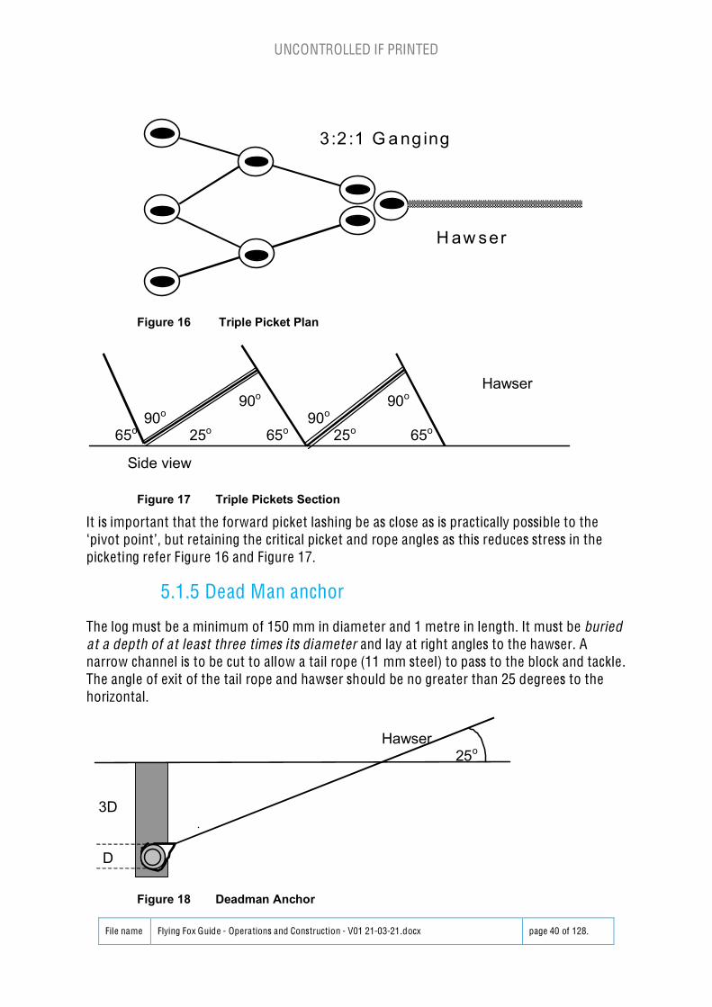
3:2 :1 G a ng ing
H aw ser
Fig 26Figure 16 Triple Picket Plan
Hawser 90o 90o
90o 90o
65o 25o 65o 25o 65o
Side view fig 27
Figure 17 Triple Pickets Section
It is important that the forward picket lashing be as close as is practically possible to the‘pivot point’, but retaining the crit ical picket and rope angles as this reduces stress in thepicketing refer Figure 16 and Figure 17.
5.1.5 Dead Man anchor
The log must be a minimum of 150 mm in diameter and 1 metre in length. It must be buriedat a depth of at least three times its diameter and lay at right angles to the hawser. Anarrow channel is to be cut to allow a tail rope (11 mm steel) to pass to the block and tackle.The angle of exit of the tail rope and hawser should be no greater than 25 degrees to thehorizontal.
Hawser25o
3D
D fig 30
Figure 18 Deadman Anchor
UNCONTROLLED IF PRINTED
File name Flying Fox Guide - Operations and Construction - V01 21-03-21.docx page 41 of 128.
5.1.6 Ground Plates
Flat to ground plates, as singles, doubles, V’s etc. using offset pegs (as used by Fire Rescue)are banned.
Any design that addresses the ‘lifting’ effect of the hawser on the leading plate, can besubmitted to FFSAC for evaluation.
5.1.7 Other Man Made Anchorages
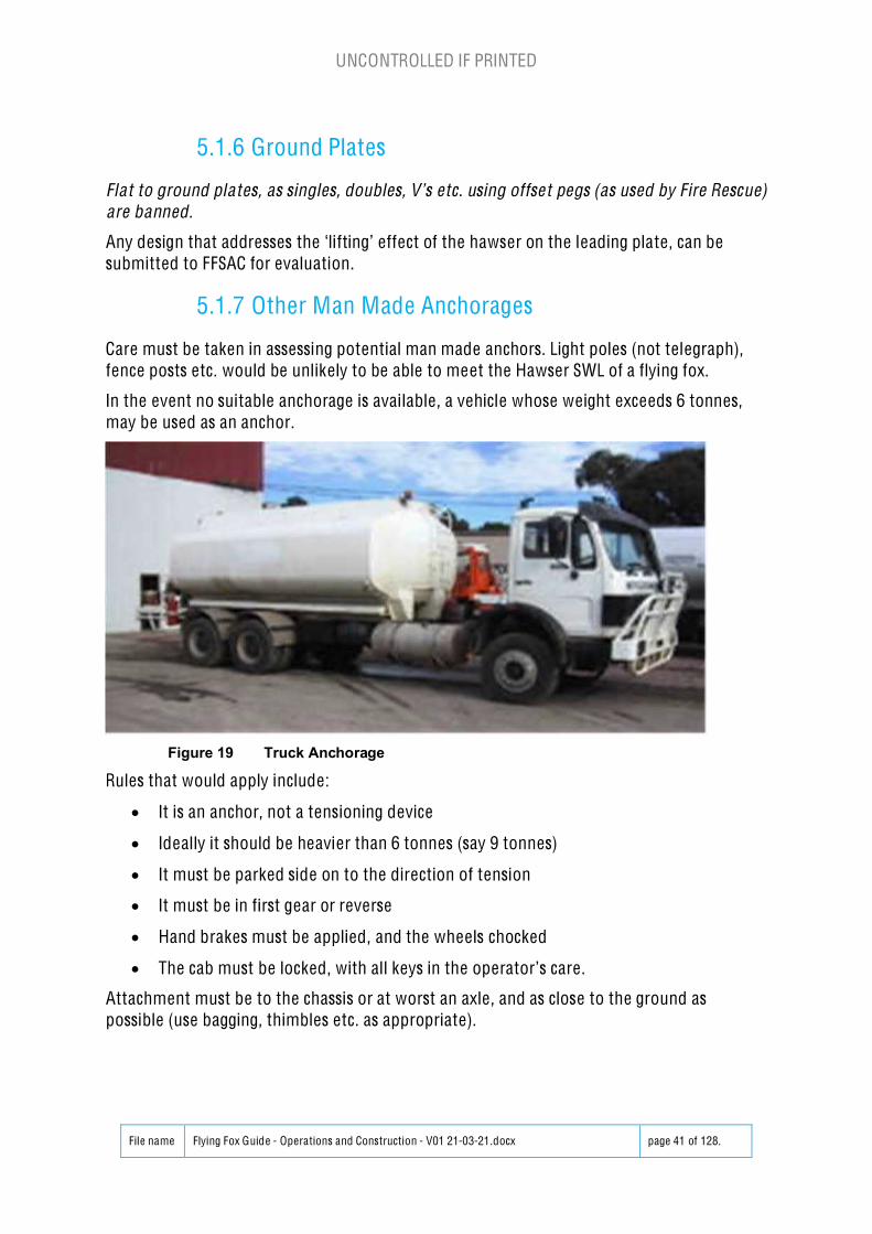
Care must be taken in assessing potential man made anchors. Light poles (not telegraph),fence posts etc. would be unlikely to be able to meet the Hawser SWL of a flying fox.
In the event no suitable anchorage is avai lable, a vehicle whose weight exceeds 6 tonnes,may be used as an anchor.
Figure 19 Truck Anchorage
Rules that would apply include:
x It is an anchor, not a tensioning device
x Ideally it should be heavier than 6 tonnes (say 9 tonnes)
x It must be parked side on to the direction of tension
x It must be in first gear or reverse
x Hand brakes must be applied, and the wheels chocked
x The cab must be locked, with all keys in the operator’s care.
Attachment must be to the chassis or at worst an axle, and as close to the ground aspossible (use bagging, thimbles etc. as appropriate).
UNCONTROLLED IF PRINTED
File name Flying Fox Guide - Operations and Construction - V01 21-03-21.docx page 42 of 128.
5.2 Shear Legs and Towers
5.2.1 Single Hawser Shear Leg
Generally, use spars either made or purchased specifically for use in a Fox’s shear legs. If anadditional spar was required, bear in mind that dead timber in a forest, by the time it landson earth, is likely more brittle than longitudinally robust . All such spars would need to besoundly ‘rung’ against a rock, hard ground or a bigger spar/ branch etc to determine if it was‘true’ for use as a spar. Spars sha ll be minimum of 125mm diameter.
The lashing ropes shall be 12mm diameter natura l fibre rope, as shall the guys.
300mmmin
Tied hessianIn saddle
Sheerlashing
2B
Square lashing
Heeled min200mm inground
BFig 14a
Figure 20 Single Hawser Shear Leg Construction
To avoid toppling, the shear legs must be positioned so that they are directly in line with thenatural lay of the hawser between the anchorages.
If of benefit, addit ional cross stays may be added to form a ladder to facilitate access to theflying fox.
UNCONTROLLED IF PRINTED
File name Flying Fox Guide - Operations and Construction - V01 21-03-21.docx page 43 of 128.
5.2.2 Dual Hawser Shear Leg
‘Squared’ shear legs are required for dual hawser foxes. Spars sha ll be minimum of 125mmdiameter. A diagona l brace, 90 mm minimum, is required within the frame.
Care must be taken to erect the shear legs with the load supporting cross spar on theanchor side of the frame. This minimises stress in the system and results in less load on thesquare lashings.
Tied hessian 300mm min
Hawser
Cross spar onAnchor sideof frame Square lashing
2B
Square lashing
Heeled min BSide View 200mm fig 14b
in ground Square Sheer Leg
Figure 21 Dua l Hawser Shear Leg Construction
The shear legs are to be suitably guyed in the vertical position to prevent fall ing forward orbackwards. It should be noted that there will be slight movement in the shear leg structurewith a dual hawser as only one hawser will be fully loaded at a time during operation.
Single picket anchor support for each guy usually suffices if there are reasonable soilconditions, however the same checks apply as per the anchor picket movement. Use theguys anchorage angles as illustrated in Figure 23.
Consideration should be given to providing protection to the fibre rope as it is loopedaround the picket, i.e. with short PVC pipe lengths, ensuring that it will not lead to the ropemoving up the picket when loaded.
UNCONTROLLED IF PRINTED
File name Flying Fox Guide - Operations and Construction - V01 21-03-21.docx page 44 of 128.
Figure 22 Picket Fibre Rope Protection
Guys should be tied off using a rolling hitch to allow repeated tensioning if required duringinspections. Consider also making a double turn on the rolling hitch to increase the tensionprovided on the hitch.
Figure 23 Shear Leg Construction Guy Ropes
UNCONTROLLED IF PRINTED
File name Flying Fox Guide - Operations and Construction - V01 21-03-21.docx page 45 of 128.
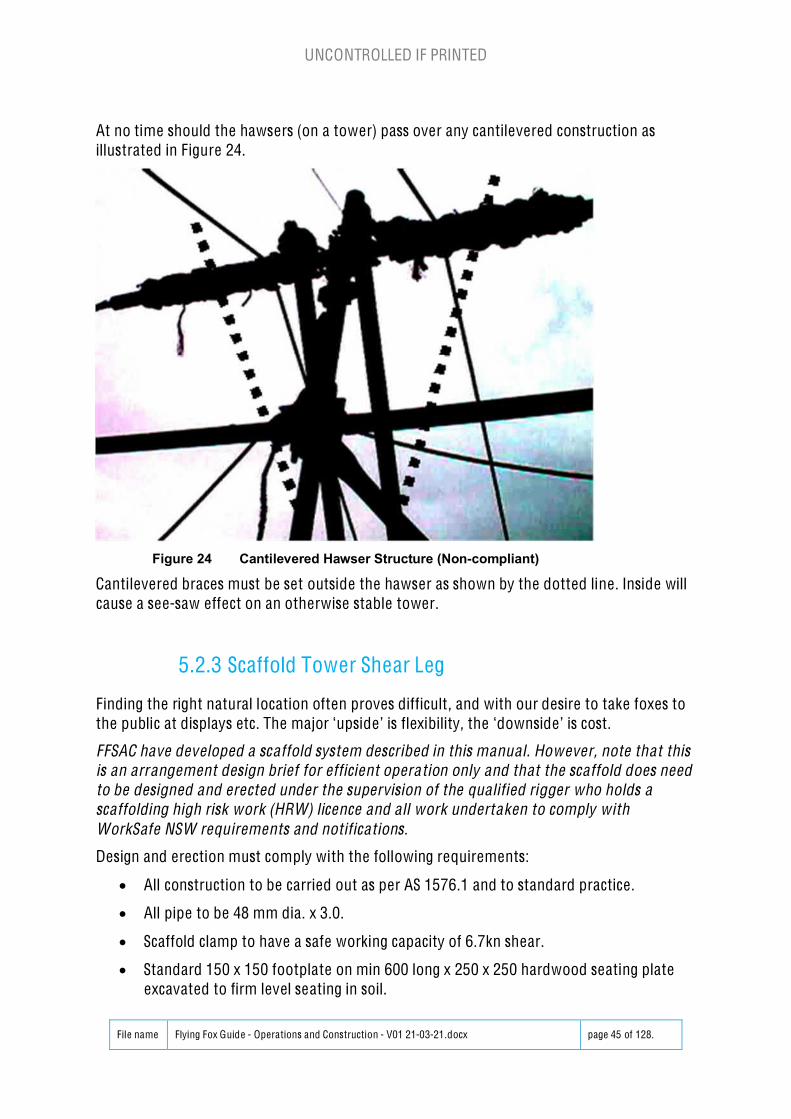
At no time should the hawsers (on a tower) pass over any cantilevered construction asillustrated in Figure 24.
Cantilevered braces must be set outside the hawser as shown by the dotted line. Inside willcause a see-saw effect on an otherwise stable tower.
5.2.3 Scaffold Tower Shear Leg
Finding the right natural location often proves difficult , and with our desire to take foxes tothe public at displays etc. The major ‘upside’ is flexibility, the ‘downside’ is cost.
FFSAC have developed a scaffold system described in this manua l. However, note that thisis an arrangement design brief for efficient opera tion only and that the scaffold does needto be designed and erected under the supervision of the qua lified rigger who holds ascaffolding high risk work (HRW) licence and a ll work undertaken to comply withWorkSafe NSW requirements and notifications.
Design and erection must comply with the following requirements:
x All construction to be carried out as per AS 1576.1 and to standard practice.
x All pipe to be 48 mm dia. x 3.0.
x Scaffold clamp to have a safe working capacity of 6.7kn shear.
x Standard 150 x 150 footplate on min 600 long x 250 x 250 hardwood seating plateexcavated to firm level seating in soil.
UNCONTROLLED IF PRINTED
File name Flying Fox Guide - Operations and Construction - V01 21-03-21.docx page 46 of 128.
x The frame is to be guyed as shown, to suitable ground connections in accordancewith anchorages defined in Section 5.
x Guy ropes are to be a minimum of 12 mm dia. and a min of 14m long from anchor totop scaffold tower.
The scaffold frame supports must be founded in all cases on firm natural undisturbed soilhaving a minimum bearing capacity of 150 kPa (normal firm dry topsoil overlaying clay orcompact sand in the Sydney region would easily have this capacity, but where in doubtprofessional advice should be sought). Areas of concern would be uncompacted fill, loosesand, waterlogged soil etc.
Scaffold frame and other ropeway supports wi ll be located on essentially level ground. (i.e .on a slope of no more than one in ten in any direct ion).
The scaffold frame is to be constructed using standard components of certified capacity,that are in good and serviceable condit ion.
The frame must be constructed in a manner which meets Workcover Authority and otherstatutory requirements.
The hawsers wi ll not be connected to the ledger bearer but must be free to slide along thebearer in the direction of their span.
The hawsers are to be suitably restrained against damage due to sideways movementagainst the scaffolding components by means of fabric restraints such as sacking laid aroundthe bearer or similar.
The operation of the ropeway must always be supervised by a qualified Scout Association ofAustralia, NSW Branch Flying Fox ‘Advanced Guide’, or ‘Supervisor’, the latter wheremembers of the public are participating.
The above aspects are crit ical for the scaffold structure described in this section to meet thedesign performance criteria.
UNCONTROLLED IF PRINTED
File name Flying Fox Guide - Operations and Construction - V01 21-03-21.docx page 47 of 128.
Figure 25 Scaffold Tower
UNCONTROLLED IF PRINTED
File name Flying Fox Guide - Operations and Construction - V01 21-03-21.docx page 48 of 128.
Figure 26 Scaffold Tower
UNCONTROLLED IF PRINTED
File name Flying Fox Guide - Operations and Construction - V01 21-03-21.docx page 49 of 128.
5.2.4 Fabricated Steel Tower Shear Leg
1) Ensure all parts areavailable2 x Uprights1 x Top Cross Bar1 x Bottom Cross Bar2 x Diagonal Braces2 x Upright Feet2 x Wooden Spacer Blocks14 x High Tensile Bolts14 x High Tensile Nuts28 x Steel Washers
2) UprightsLay out two Uprightsapprox. 3 m apartPlace Wooden SpacerBlocks under each end
3) FeetInsert Feet Plates intobottom of each UprightInsert four, 12mm x100mm, High Tensile Bolts,Washers and NutsTighten all four Bolts
UNCONTROLLED IF PRINTED
File name Flying Fox Guide - Operations and Construction - V01 21-03-21.docx page 50 of 128.
4) Top Cross BarPlace Top Cross Bar (twoholes closer to centre) ontop of Uprights over top setof holesInsert two, 12mm x 175mm,High Tensile Bolts,Washers and NutsDo bolts up loosely
5) Diagonal BracesSelect Diagonal Brace(steel with plates welded toeach side at one end) andbolt to Top Cross BarPlace plain under top CrossBar and bolt into the twoholes in the centre of TopBarSlide side plates on otherends over uprights on eachside (should line up with 6thhole below Top Bar)Insert bolts and do uploosely6) Bottom Cross BarLay Bottom Cross Bar ontop of Uprights andDiagonal Braces (shouldline up with 4th hole belowTop Bar)Place bolts throughUprights and DiagonalBracesInsert four, 12mm x175mm, High Tensile Bolts,Washers and NutsDo bolts up loosely
UNCONTROLLED IF PRINTED
File name Flying Fox Guide - Operations and Construction - V01 21-03-21.docx page 51 of 128.
7) Tension BoltsTighten all Bolts securely
UNCONTROLLED IF PRINTED
File name Flying Fox Guide - Operations and Construction - V01 21-03-21.docx page 52 of 128.
8) Set up Gin PoleSet up and construction of the Gin Pole must comply with the following requirements:The height of the Gin Pole is equal to the height of the shear leg being raised.The base of the Gin Pole is placed at the mid-point between the base of the two shear legs and150mm in the groundThe Gin Pole Fixed rope must be secured to the top of the Gin Pole with a Pipe Hitch containingno less 8 full turns.The Gin Pole Fixed rope must be a minimum of 2900kg Tensile Strength e.g. 12mm diameterstatic kernmantle rope.The knot securing the Gin Pole Fixed rope to the mid-point of the top of the shear legs should arethreaded double Figure 8 or running Bowline.The length of the Gin Pole Fixed rope between the Pipe Hitch and the top of the shear leg mustbe equal to the height of the shear leg.The star pickets supporting the Gin pole must be 1.5 times the height of the shear leg from thebase of the Gin pole. The star pickets, Gin Pole base and the shear leg base must form astraight line.The guy ropes supporting the Gin Pole are secured to the top of the Gin Pole using a pipe hitchor similar knot that will not slip down.A Turfer cable winch must be used to raise the Gin pole.The anchors for the Turfer are 2 off star pickets joined with a Banjo Lashing. This anchor is tobe placed 1.5 times the height of the shear leg from the base of Gin Pole and on centre line ofthe shear leg and Gin Pole.The hook on the Turfer is connected to the Gin Pole using an appropriate sling. e.g. 2 tonnesling.Double check the guy ropes are installed on the shear legs as well as string line, hawsers,return ropes and pulleys, safety ropes and other hardware for the shear leg.Ensure the star pickets are installed ready for the shear leg guy ropes.Use the Turfer to raise the shear leg to the limit of the Gin Pole. Operators to take control of theshear leg using the guy ropes to fully raise the tower into correct position.Once the shear leg is secured with the guy ropes the Gin Pole, Gin Pole fixed rope, Gin Poleguy ropes, turfer and turfer anchoring star pickets can be removed.
9) Attach Platform to TowerRaise tower enough toattach platformAttach platform with u boltsand cables10) Raise Tower
Figure 27 Fabricated Steel Tower Erection
UNCONTROLLED IF PRINTED
File name Flying Fox Guide - Operations and Construction - V01 21-03-21.docx page 53 of 128.
5.3 Braking Systems
5.3.1 Static Brake Setout
The running end of the ropes are secured to steel pickets so that If the participant hits thestatic brake and it moves to the limit of its travel they cannot Swing up and hit the shear leg,refer Figure 28.
Maximum Brake PointHawser
Brake travelArc Minimum Brake Point
Brake Brake On Off
fig 36
Figure 28 Static Brake Setout
A convenient but safe knot must be used on the anchorages, i.e. rolling hitches, alpine butterflyand figure loops are considered appropriate, but will depend on design, and the lay of the rope.
Consideration should be given to providing protection to the rope as it is looped around thepicket , i.e. with short PVC pipe lengths of using shackles over the star pickets, ensuring that itwill not lead to the rope moving up the picket when loaded.
5.3.2 Static Brake
The static brake is secondary braking system with the aim to prevent the participant hitt ing theshear leg if the primary braking system, which must be a dynamic braking system, fails. It ismade using dynamic kernmantle rope with a fixed length to achieve the set out as described inSection 5.3.1.
Note: AS 2316.2.1 stipulates the maximum imposed load on the participant sha ll not exceed0.8kN (approx. 81.6kg) and the maximum dynamic load is 6kN (approx. 611.8kg).
UNCONTROLLED IF PRINTED
File name Flying Fox Guide - Operations and Construction - V01 21-03-21.docx page 54 of 128.
Figure 29 Static Brake Arrangement
For a Dual hawser system tie two alpine butterfly knots close to the middle of the rope and atthe width of the hawsers. Install either on each hawser nylon blocks and rated bow shacklesconnected to the alpine butterfly knots.
5.3.3 Gravity Brake
A gravity brake is a passive braking system which allows for slow deceleration. It is where 1/3of the span (or more) is uphill as per Figure 30.
Figure 30 Tree Shear to Tree Shear Legs with Natural Brake
UNCONTROLLED IF PRINTED
File name Flying Fox Guide - Operations and Construction - V01 21-03-21.docx page 55 of 128.
5.3.4 Dynamic Brake
The maximum effective speed (velocity) is 11 km / h average (3.055 m /sec.) in accordance toAS2555.
This is calculated when initially testing the system. To determine maximum speed:
Measure the distance from the launch platform to the ‘final stop’ position.
Place a mass equivalent to the maximum rider weight on the trolley. e.g. 120kg
With a stop-watch time the distance from launch to final stop.
Calculate the velocity of the mass.
Example I (Acceptable velocity)
If the distance travelled is 50m and the duration was 17.5 seconds.
Velocity = 50m / 17.5 seconds
Velocity = 2.85m/s
This is less than 3.055m/s and is acceptable
Example II (Maximum velocity)
If the distance travelled is 50m and the duration was 15.5 seconds.
Velocity = 50m / 16.366 seconds
Velocity = 3.055m/s
This is the maximum velocity acceptable
Example III (Unacceptable velocity)
If the distance travelled is 50m and the duration was 13.5 seconds.
Velocity = 50m / 17.5 seconds
Velocity = 3.7m/s
This is greater than 3.055m/s and is unacceptable
According to Australian Standard AS 2316.2.1:2016, Artificial climbing structures and challengecourses, Part 2.1: Flying foxes and challenge ropes courses Construction and safetyrequirements, the maximum Imposed Load per person shall not exceed 0.8kN 81.55kg) and themaximum Dynamic Load is 6kN (611.6 kg). If the maximum velocity of 3.055m/s is notexceeded and a gradual deceleration (described in this section) is used e.g. tyre, chain orbungee brakes, the maximum force imposed the participant is subject to should not exceed0.8kN (81.5kg) and a Dynamic Load of 6kN (611.6 kg).
Each flying fox is required to have a minimum of two braking systems.
If the towing rope is used as part of a braking system, the rope capacity wil l need to beincreased to compensate for the additional load.
UNCONTROLLED IF PRINTED
File name Flying Fox Guide - Operations and Construction - V01 21-03-21.docx page 56 of 128.
5.3.5 Dual Hawser Dynamic Brakes
Dual hawser Flying Foxes are ideal for high volume throughput of ‘trolleys’, as the recovery ofthe trolley is done automatically, and manual recovery is overcome.
‘Bottom end’ brakes can be modifications of previously discussed systems, such as bungee, inline, tyres in line, etc., but where stacked tyres are used, the tow line is not available forbraking, as it is used for trolley recovery through a system of pulleys, or a single pulley.
A dedicated braking rope is required and can be constructed as per Figure 31.
The brake line is tensioned by using a stabiliser rope, tied to the bottom shear leg, which liftsthe first tyre. The tension is necessary to stop the brake rope dragging to the ground. The loopsystem to the brake blocks allows only the active block to action the brake, and the length ofthe loop will determine when the non-active block is brought into play. The stabilised distancemust be greater than the total draw of the balance of the tyre brake.
It has been found a length of shock cord wil l negate any slack in the stabiliser rope, at the pointof brake block impact. This shock cord must be secured under tension. The shock cord is bestfitted approximately halving the distance of travel between the shear leg and brake blocks andcan be run through a pulley to de-crease wear on the cord. The shock cord should not be usedin place of the stabiliser rope.
Figure 31 Dua l Hawser Dynamic Brake Layout
UNCONTROLLED IF PRINTED
File name Flying Fox Guide - Operations and Construction - V01 21-03-21.docx page 57 of 128.
Figure 32 Double Hawser Dynamic Brake
Consideration should be given to providing protection to the rope as it is looped around thepicket , i.e. with short PVC pipe lengths of using shackles over the star pickets, ensuring that itwill not lead to the rope moving up the picket when loaded.
Brakes can be applied through the tow line. By using a 12 mm diameter natural fibre rope, runthe tow line back through a pulley located near the span end, but not to foul the hawser, andthen run the pulley to ground. Attach to this a minimum of 3 car tyres, the configuration ofwhich will be determined by the design of the flying fox, speed and weight of participants. Thisis one of the preferred methods.
UNCONTROLLED IF PRINTED
File name Flying Fox Guide - Operations and Construction - V01 21-03-21.docx page 58 of 128.
Start of application Mid point Full application
Ground Level fig 38
Figure 33 Dynamic Brake - Tyre Weight
The spacing between the tyres is determined by the length on the hawser over which braking isapplied.
If the space required for tyres, when transporting or where the brakes are physically installed,heavy large link chains can be applied through the tow line. By using a 12 mm diameter naturalfibre rope, run the tow line back through a pulley located near the span end leg, but not to foulthe hawser, and then run the pulley to ground. Alternatively, the tow line can be run through ablock system to bring it back to the lower shear leg. This has the advantage of not having tocarry the weights up a steep incline.
The chains should be grouped in separate weight configurations and attached on the otherchains to suit the weight take up required, which can be added or removed to suit the design ofthe flying fox, speed and weight of participants. This is another one of the preferred methods.
UNCONTROLLED IF PRINTED
File name Flying Fox Guide - Operations and Construction - V01 21-03-21.docx page 59 of 128.
Figure 34 Dynamic Brake - Chain Weight
Where such brakes are used, care must be taken to ensure that the brake mechanism cannotbe fouled, and that it is a danger to no one.
The brake design for the heaviest load will be ‘over efficient’ on lighter loads, but as alwayssafety will be the first consideration.
In a dual hawser set up the brake needs to be under tension, and a fifth tyre mayberecommended.
UNCONTROLLED IF PRINTED
File name Flying Fox Guide - Operations and Construction - V01 21-03-21.docx page 60 of 128.
5.3.6 Bungee Dynamic Brakes
A length of 10 mm shock cord is selected that will give the required deceleration. For safetyreasons four minimum are required for each side of the nylon block. These lines must befitted with nylon thimbles and are recommended to be secured with a figure of eight knot orwhipped fastening securing thimble.
The anchor end must be secured in a manner that wi ll not ride off the anchor, and if necessary,a 12 mm sisal rope extension can be included at the anchor end to extend the total length ofthe anchor line. If such a brake is used in combination with an in-line brake as described abovethe maximum draw out length of both brakes can be identical, but the initial location on thehawser may differ. Obviously load weight will vary the final rest ing place of the bungee brake.
Care should be taken to reduce any ‘slingshot’ effect.
5.3.7 In-Line Tyre Braking System
Alternatively, the static brake can be made up of inline tyre arrangement indicated in Figure35. The tyres are pierced, and the hawser passes through them).
Figure 35 Hawser In-Line Tyre Brake
The tyres under maximum compression, must keep the arced passenger free of the shear legs,or similar. The negative of this design is weight on the hawser and difficulty installing safely athigh level. (Beware!)
UNCONTROLLED IF PRINTED
File name Flying Fox Guide - Operations and Construction - V01 21-03-21.docx page 61 of 128.
5.4 Hawser and Tension System
5.4.1 Hawser Loading Theory
The relationship between participant weight, hawser included angle (% of catenary) andsystem loads (Resultant Forces) is critical. According to (Warner C, 1992, A Fresh Approach toKnotting and Ropework, National Library of Australia), Resultant Force changes with differentangles. See below copy of that text.
Note that these forces apply to the hawser and a ll in line components, including shackles,turnbuckles, anchors and associa ted slings. FFSAC are recommending a minimum 4Tcomponents be used for flying foxes less than 100m, 5% sag in the hawser and maximumparticipant weight of 120kg.
If your weak anchor points are well spread out sideways, you must make your linkagessufficiently long to allow for the resultant forces at various angles (549). If a load “L” is sharedbetween two leg of a rope forming an angle “A”, then the load “T” in the legs is not far fromapproximately 1/2L if the angle ”A” is less than about 75o, but then increases rapidly withincreasing angle, so that it is 3/4L at 90o, L at 120o, 2L at 150o, 4L at 165o and 12L at 175o (thisassumes that the legs are straight, with no sag). You should therefore never exceed 120o
between legs of a self-equalising anchor.
Figure 36 Hawser Forces
It is the same principles which apply to the relation between the weight of a person crossing arope bridge and loading int eh rope. That is why such rope bridges must sag quite a bit, or elsehave very strong rope.
The minimum catenary is 5% = 168.57 degrees (calculated using trigonometry). Applyinginterpolation Warner’s text above, the Resultant Forces “T” on the system and anchors isapproximately 6.75 x Load. If we have a 120kg maximum participant weight the ResultantForces on the system: 6.75 x 120kg = 810kg.
UNCONTROLLED IF PRINTED
File name Flying Fox Guide - Operations and Construction - V01 21-03-21.docx page 62 of 128.
This does not take into consideration the mass of the hawser itself or dynamic loads. i.e. theparticipant takes a running start onto the flying fox. At 164 degrees included angle in thehawser the Resultant Forces on the system reduces to less than 4 x Load.
Resultant Forces on the system: <4 x 120kg = <480kg.
At 175 degrees included angle in the hawser the Resultant Forces on the system increases to12 x Load.
Resultant Forces on the system = 12 x 120kg = 1440kg.
To keep system loads to a minimum to 5% minimum catenary must be enforced. Participantmass should not exceed 120kg and participants to be launched from a static position i.e. NOrunning launches.
5.4.2 Hawser Tensioning
Once secured, the tensioning of the hawser may take place. Any “block and tackle”, “chainblock” / ”cum-along” or ‘turfer’ used, while not being required to be rated, needs to be in goodcondition to avoid accidents – this especially applies to the rope used on the block and the ropeattaching to the hawser via a ‘lizard’ or other method. Measuring of the catenary formed witha known weight (at the suggested limit or lesser) in the middle of the hawser is required.Notation of data obtained is a requisite of any Fox construction.
The minimum catenary of the Hawser shall be 5% or an included angle on the hawser atmidpoint of 168 degrees. This ensures the resultant forces applied to the system do notexponentially increase above rated system loads.
5.4.3 Block and tackle ‘in line’
An ‘in line’ eye should be placed in the hawser on the non-traverse side of the shear legs. Thiscan be achieved by using a correctly installed appropriately rated wedge socket or eye anddouble turnbuckle clamps.
The hawser is then attached to the block and tackle (triple sheave end) with a moussed shackleof minimum 3.1 tonne capacity. The double sheave block is attached to the anchorage selectedby using a sling, rope and or shackle for triple picket, or a tail rope for log and picket, or deadman anchorage.
If required a suitable tail rope can be paralleled to the block and tackle.
Identical fixings are used where the hawser is to flow through, and the double sheaved end ofthe block and tackle wi ll need to be ‘l izarded’ to the hawser, however, the lizard is not to bethe main load support connection.
5.4.4 Turnbuckles
A single or tow inline 24 mm turnbuckle Rated at 4T (minimum) may be inserted on an ‘in lineeye’ configuration, to facilitate minor tensioning and catenary adjustments. These turnbuckleand associated shackles are to be moussed to avoid the potential for it to unwind under load.
UNCONTROLLED IF PRINTED
File name Flying Fox Guide - Operations and Construction - V01 21-03-21.docx page 63 of 128.
Figure 37 Turnbuckle Hawser Base Clamp Tensioning
In an ‘in line eye’ configuration the thimble eye in the hawser should be set and secured bydouble base clamps See Figure 43 and Figure 44. A minimum of three (3) stee l hawser doublebase clamps sha ll be used to secure the thimble steel eye in the hawser, re fer Figure 37. Notethat these are critica l and must be inspected regularly for any movement.
Figure 38 Hawser Double Base Clamp Fixing
It is recommended to install tape markers adjacent to eye or one the lead side and tail end ofthe first base clamps to check on any movement, refer Figure 58.
UNCONTROLLED IF PRINTED
File name Flying Fox Guide - Operations and Construction - V01 21-03-21.docx page 64 of 128.
Remember wire rope grips are banned in any human load carrying situation.
Wire rope grips maybe used to secure the lizards to the hawser with non-human load, forsetting up hawser tension. Wire rope grips should be tensioned to 24 Nm, 18 pound-foot, 2.45kg.m. Set the ta il rope long and adjust single base clamps (6 nuts) as you adjust the tension.
5.4.5 Raising the Hawser
Raising the hawser and applying the approximate tension tensioning can be achieved usingeither “Chain block” / ”Cum-along” or ‘Turfer’ can be used as a versati le tensioning systemwhich has more flexibility than a block and tackle. Note this can then also be available and setready for rescues if required.
Figure 39 Cum-along Tensioning System
5.4.6 Hawser Catenary Tension vs Sag
Assuming a 120kg load, over a 40m span, with:
ROPELENGTH
CREATESCENTRAL SAG
AND GIVES RISE TO A HAWSERTENSION OF
42 m 6.4 m 1.6 tonnes41 m 4.5 m 2.3 tonnes
40.25m 2.2 m 4.5 tonnes
Table 2 Hawser Tension vs. Sag
UNCONTROLLED IF PRINTED
File name Flying Fox Guide - Operations and Construction - V01 21-03-21.docx page 65 of 128.
It can be seen from this that a tight rope gives a fast trip, but may overstress the rope andendanger life, so we have devised a three-level safety check on rope tension.
Step 1:
We must establish the span which may be done by:
‘Stretching’ a bricklayer’ line to minimise it’s catenary and then measuring the line length. Thedanger is that the ‘stretching’ may be significant, and the determined measure may cause anunsafe underestimation of the span.
Preferably we should use a high quality ‘non stretch’ tape measure. This will cause minoroverestimation of span (safe), due to tape catenary.
Step 2:
Refer to Table 3 Schedule of Required Sag – No Load where by taking the length of thespan you can determine the required catenary. On a light pole place a sturdy nail at thedetermined distance from the pole end. At mid span point (not mid ground point) locate thenail just above the hawser. The top of the gauge must not exceed the span line height, whilstthe gauge is vertical to the ground (not 90 degrees to span line).
Thirdly refer to Table 4 Schedule of Required Sag – Under Load where by taking thelength of the span you can determine the required sag under load. Apply a second nail to thegauge at this stated depth. Bring the trolley, with tow rope hanging to mid-span, and apply aload of at least 50% of maximum load. Test the rope under load just as the catenary wastested.
In measuring Table 3 and Table 4, light poles may be inappropriate due to site considerations,and a light marked string dropper from mid-span point may be more practical.
When all three tests perform within the guide lines above, the rope is not over-stressed. Ifone test is out, the tension must be adjusted, and all tests repeated, until we have all threetests correct.
Mid Point
C
GL Gauge Stick
Fig 34
UNCONTROLLED IF PRINTED
File name Flying Fox Guide - Operations and Construction - V01 21-03-21.docx page 66 of 128.
Figure 40 Hawser SAG Measurement
Tape measure to total ‘let out’ length and draw hawser to match curve.
Set catenary gauge and ensure span line not exceeded.
Set load gauge and ensure span line not exceeded.
Mid Point
C
Span LineHawser - Catenary
GL Hawser – Under Load Gauge Stick Gauge C Catenary Nail
Locations GL Load Nail
Fig 35
Figure 41 Hawser SAG Measurement on Slope
Where all three tests are impractical or impossible, due to site conditions etc. the first test maybe dispensed with, but more care should be taken on complet ing Table 3 and Table 4.
Where using Table 3 and Table 4 only, it may appear that the catenaries under ‘no load’ and‘load’ are performing at variance to the tables. The cause of this is most likely the catenary inthe span line, and great care should be taken if some compensation is made for this. Safety isparamount.
Under no circumstance must the loaded catenary be more than 1: 20 ratio to the span length.(i.e. less than 5% sag on span length)
FFSAC recognise the difficulty in getting a ‘straight’ span line and measure and is invest igatinglaser technology to assist with more accurate measurement.
Formula for establishing actual let out length (ALOL):
(SLOL/SS) x ACTUAL SPAN = ACTUAL LET OUT LENGTH (SS)
Example: Using the schedule closest to the actual span.
e.g. Let us assume an actual span of 76.5 metres.
(80.40/80) x 76.5 = 76.8825m or round to 76.9m
Note: The above specifications relate to steel ropes.
UNCONTROLLED IF PRINTED
File name Flying Fox Guide - Operations and Construction - V01 21-03-21.docx page 67 of 128.
SCHEDULE OF REQUIRED SAG - NO LOAD APPLIED(CATENARY)
SPAN (SSPAN) MINIMUM SAG FORUNLOADED ROPE (SSAG)
10 m 0.44 m
20 m 0.87 m
40 m 1.75 m
60 m 2.64 m
80 m 3.53 m
100 m 4.43 m
Table 3 Schedule of Required Sag – No Load
Formula for establishing actual Sag - Unloaded (ASAGU)
(SSAG/SSPAN) x ACTUAL SPAN = ACTUAL SAG-UNLOADED (ASAGU)
Example: Using the schedule above for the Actual Span Length
e.g. Let us assume an actual span of 76.5 metres.
(3.53/80) x 76.5 = 3.3755625m or round to 3.38m
Note: The above specifications relate to steel ropes.
SCHEDULE OF REQUIRED SAG – UNDER LOAD APPLIED
(ASSUMING 5% SAG CATENARY)
SPAN UP TO(SSPAN)
ALLOWED SAG (SSAG)
500mm 0.025m
1m 0.05m
2m 0.1m
3m 0.15m
4m 0.2m
5m 0.25m
6m 0.3m
7m 0.35m
8m 0.4m
9m 0.45m
10m 0.5m
20m 1.0m
30m 1.5m
40m 2.0m
50m 2.5m
UNCONTROLLED IF PRINTED
File name Flying Fox Guide - Operations and Construction - V01 21-03-21.docx page 68 of 128.
60m 3.0m
70m 3.5m
80m 4.0m
90m 4.5m
100m 5.0m
Table 4 Schedule of Required Sag – Under Load
Formula for establishing actual Sag - Unloaded (ASAGU)
(SSAG/SSPAN) x ACTUAL SPAN = ACTUAL SAG-UNLOADED (ASAGU)
Example: Using the schedule above for the Actual Span Length
e.g. Let us assume an actual span of 76.43 metres rounded up to 76.5m
Therefore, we allow:
70m = 3.5
+ 6m = 0.3
+ 500mm = 0.025
For 76.5m = 3.825m
(3.53/80) x 76.5 (SPAN) = 3.3755625m or round to 3.38m (SAG)
Note: The above specifications relate to steel ropes.
5.5 Fox Mount and Dismounting Considerations
5.5.1 Fox Mounting
Site depending, this can be a dangerous part of the activity and all care needs to be taken here,all operators shall be on fixed belays if there is any chance of a fall from height. If appropriate,participants may need to be separately belayed prior to being attached to the Fox. Ladders onuneven ground are inherently dangerous and care needs to be taken to void any risk here.
Where possible is best practice to ‘preload’ the participant onto the hawser. This reducesparticipant ‘free fall’ and thereby reduces anxiety (especially Joeys and Cubs) and greatlyreduces system dynamic loads.
To preload the hawser:
x Participant either stand or sit on the launch platform.
x Connect Petzl RIG, GriGri or similar device affixed to the dropper to participants harness(bridge) OR crimped wire dropper. Tri-lock, Mag-lock or similar automatically lockingdevices should be used and NOT relying on operators screwing up carabiner.
x Connect safety backup to participants harness (bridge) on a separate carabineer to aseparate fixing on the trolley, i.e. a separate independent safety line with no commonpoints apart from the actual trolley and harness.
UNCONTROLLED IF PRINTED
File name Flying Fox Guide - Operations and Construction - V01 21-03-21.docx page 69 of 128.
x Simultaneously pull down on the hawser (to tension it) and pull rope though the PetzlRIG / Gri-Gri so the participant should feel as though they are being lifted by thedropper. For a fixed dropper if they can walk to a position on the launch platform or sitso they are suspended prior to release.
x Double check connections to the participant and lock off Petzl RIG. If a Gri-Gri is used aReverse Marlin Spike Hitch MUST be placed in the running end of the dropper ropedirectly below the Gri-Gri.
x Participant is safe for launch.
The preference I to have a solid launch platform which can be natural ground/rock, scaffold orspecific platform offering adequate space for at last the operator and participant to movearound safely for launch. The use of ladders for a launch is NOT preferred.
If a tall tree is available offering a high top shear leg a standard 3-4m scaffold platform can a beused, which can generally be hired and has rental company instructions for assembly. Providingsuch a platform offers an easier launch for younger scout members such as Joey’s and Cub’s.Such scaffold structures can be assembled by the fox team without necessarily having alicensed rigger. Note however that even this scaffold does need to be guyed as per the detaileddescription for scaffold towers.
5.5.2 Fox Dismounting
See above. The return journey, on foot, to the top of the run if that is what happens) needs tobe safe – roped off areas are important here! Site dependent, additional Fox staff may berequired to ensure no possibility of excited riders walking in front of an incoming Fox withpotentially disastrous results.
The embarking and disembarking positions must be such that there is no danger to thepassengers and/or spectators as a result of the surrounding terrain. Suit-able clear access isessential.
The hawser height , under load, at embarking and disembarking points, must be enough toallow the tallest passenger to be seated in the harness (incapable of touching the hawser ortrolley) and legs if fully extended not touching the ground at any point along the travel .
Suitable steps may be needed to assist passengers dismounting from the Flying Fox.
Where embarking or disembarking requires the passenger’s feet to be more than 2 metresabove clear ground, safety lines must be used for passenger security.
In certain terrain it may be unsafe to disembark at the travel end, and in such cases nothingprecludes the tow line rope being used to transport the passenger back to the embarking pointfor disembarking. This may also apply in reverse, where the passenger boards at thedisembarking point, and is towed to the higher point before being released.
UNCONTROLLED IF PRINTED
File name Flying Fox Guide - Operations and Construction - V01 21-03-21.docx page 70 of 128.
5.6 Rescue Gear
The flying fox construction must take into consideration rescue of participants part run downto allow them to be safely lowered to the ground. Due to a range of incidents which may occur,including ensuing medical condit ions, it should be possible to lower participants to the groundsafely within a short period of time.
Depending the type of construction will determine how best to rescue participants, notehowever the means of lowering participants must be controlled and not reliant of excessivemanual handling by operators where the speed of decent is dependent on the strength of theoperators.
Rescue systems used should be rated to carry a minimum of two people and the devices usedshould be able to be used to lift and to lower the participant requiring rescue.
Considerations for rescue systems should include but is not limited to:
x load magnitude
x ability to raise the person
x ability to lower the person and rescuer
x ability to enable an activity leader to complete contact rescues.
The hawser wil l be under load with a stranded passenger, and the load must be reduced safelyand gently. We would recommend that the first option is to gently lower the hawser using ablock and tackle attached to a lizard on the hawser using 3 off double base clamps. Then thehawser can be gently slackened.
Where the jam is too high, or the topology does not easily permit slackening the hawser andalternative system needs to be planned where a second rescue trolley can be lowered downthe hawser with appropriately rated equipment to allow the participant to be safely re-attached to the hawser or rescue trolley and allowing safe lowering of the participant.
It should be noted that if a participant is unconscious, he/she can suffer Suspension Trauma(Harness Hang Syndrome or Orthostatic Intolerance) after 5 minutes hanging in a harness. Thiscan result in participant death. The rescue systems used must be safe for the operator andparticipant, effective and fast .
Possible methods include the following:
x If the participant is jammed near the launch platform, use the return line rope to haulthe participant back onto the launch platform.
x If the participant is mid span the rescuer may be able to ascend a step ladder (alreadyon site), disconnect participants safety rope and then lower the participant using theparticipants Petzl RIG.
x If the participant is mid span and the hawser is ‘higher’ the rescuer can throw a ropeover the hawser and ascend the system using a Double Rope Technique (DRT). Once upthe height of the participant the rescuer dis-connects participants safety rope and thenlowers the participant using the participants Petzl RIG whilst simultaneously controll ingtheir own descent on the DRT system.
UNCONTROLLED IF PRINTED
File name Flying Fox Guide - Operations and Construction - V01 21-03-21.docx page 71 of 128.
x Use of the independent trolley with a trailing rope run through the re-turn line pulley toallow an operator to be lowered down the run slowly to join the participant requiringrescue.
x On the dropper from the travelling bock the rescuer has descender system arranged,sufficiently rated to allow two persons to be safely lowered. This can be a proprietaryrescue ascender such as the CMC Rescue MPD or Petzl’s JAG system, which allows theoperator to raise or lower without changing the rope, or other rock climbing descender.
If a proprietary rescue raising and lower devices are not available a pulley system can be usedto raise the participant to be rescued. Fixed at high level directly under the trolley and fixed tothe participants harness carabiner and enough trai ling rope so operators on the ground canraise the participant allowing them to be disconnected from their dropper and fixed bycarabineer to the rescuer dropper. Note that a safety tape should be fixed to the participantduring this transfer.
Once the rescuer and participant are fixed to the rescuers descender the rescuer can operatethe descender to safely lower them both to the ground.
It should be assumed that the participant to be rescued is not able to assist in the rescue, asthey may have injuries, be unconscious and not possess the necessary skill.
Rescue equipment must be readily available to ensure rapid deployment is possible. Theequipment must be suitably rated for the purpose, i.e. rock climbing rescue equipment, andsuitable for the flying fox arrangement installed.
The qualified fox team must be trained in the use of the rescue equipment and should bepracticed periodically.
The expected peak load and possible additional loads if a rescue is carried out must beconsidered when determining equipment loading.
Note that the lowering of shear legs and or lowering the hawser can only be used as a rescuemeans if an arrangement can made to lower components slow and in a fully controlledmanner.
Note that the lizard can only be used to lower the hawser if it is fixed as per a fully load rateddouble base clamp arrangement as per the hawser end eyelet and a cum-along is used toslowly lower the hawser.
UNCONTROLLED IF PRINTED
File name Flying Fox Guide - Operations and Construction - V01 21-03-21.docx page 72 of 128.
6.0 Equipment6.1 General
The equipment selected must be suitable for the purpose it wi ll be used.
This includes ensuring all equipment:
x meets any legislative or regulatory requirements
x is appropriately serviced, stored and maintained
x is appropriate in style, size, quality and quantity for the activity and by FFSAC.
6.2 Hawser Specification
The hawser is the main weight bearing rope that will carry the trolley.
The Hawser specifications are:
Material MaximumSpan
MinimumDiameter
Construction
MaximumLoad
Steel – Galvanised 100 m 11 mm 7/19 120 kg
Steel – Galvanised 100 m 11 mm 6/24 120 kg
Table 5 Hawser Specification
6.3 Care of Hawser
When a new HAWSER rope is purchased ensure a one metre sample of the new rope retainedin new condition (for cross reference) and a register which records specifically for each rope:
x date and place of purchase, specification and length.
x date of rope usage, weather conditions, fixing methods, span, ‘let out’
x length, catenary, load allowance, maximum weight, estimated journeys, and brakingsystems.
A sample format shown in Table 6.
Each Flying Fox activity is to be recorded on the Flying Fox and Hawser Usage Report shown inTable 7.
It is essential that proper care is given to the Hawser, including:
x Check for broken strands which may be caused by age, abuse, or trolley wear.
x Ensure the rope is coiled and stored correctly in a dry place free of grit , grime and dirt.
x Open lay and check for rust .
UNCONTROLLED IF PRINTED
File name Flying Fox Guide - Operations and Construction - V01 21-03-21.docx page 73 of 128.
Ensure rope is cleaned, inspected and lubricated before storage, after use.
Any rope (be it of any material or construction) that is suspect should be cut to short lengths toensure that it can no longer be used.
Annually the ropes, together with all blocks and tackles, including trolleys, will requireindependent written certification by a registered rigger or other persons authorised by FFSAC.This may be ‘logged’ in the register.
Figure 42 Uncoiling (and coiling in reverse)
6.4 Hawser End Fixings
Where any rope has an eye inserted this MUST include the correctly sized thimble and beaffixed in an approved manner that allows minimal or no reduction in the capacity of the rope.(‘In line’ eyes will still require a thimble, and a temporary securing method).
All rope ends, other than eyes, must be finished in an approved manner, which includesswaged fixing for steel hawsers or the three (3) sets of double base clamps with thimbles asindicated in Figure 43.
Note: Bulldog clips, wire rope grips, single U-bolts are not permitted for use on Hawsers asthey are unreliable and tend to damage to w ire rope.
UNCONTROLLED IF PRINTED
File name Flying Fox Guide - Operations and Construction - V01 21-03-21.docx page 74 of 128.
Figure 43 Double Base Clamp Wire Rope Grips
Figure 44 Double Base Clamp
TWIST is defined as S twist (left-hand lay) and Z twist (right hand lay).
Figure 45 Wire Twist
S twist and Z twist ropes should never be coupled.
UNCONTROLLED IF PRINTED
File name Flying Fox Guide - Operations and Construction - V01 21-03-21.docx page 75 of 128.
6.5 Hawser Damage
As outer wires wear and the wire rope is bent over sheaves, the fatigue will start to breakthem. The maximum number of broken wires in a flexible steel wire rope is 10% of the totalnumber of wires over 8 times the diameter of the rope.
Our ‘approved’ minimum rope is 11mm diameter 7 /19 or 6 / 24 Seale.
For an example 7/19 wire:
Diameter 11 x 8 = 88 mm length
Wires 7 x 19 = 133
at 10% = 13.3 wires
Therefore, the total number of broken wires permitted in 88 mm is 13.
Chemical: avoid contact with any harmful agents.
Physical damage and degradation
External Wear: as evidenced by projecting broken surface fibres, unless extensive, is harmless,and may even help protect internal fibres.
Local Abrasion: caused by dragging a rope over a sharp edge under tension, may cause seriousloss of strength. Serious damage to one strand or moderate damage to more than one strand,warrants rejection.
Cuts and Contusions: Cuts are caused by a rope under tension over a sharp edge, andcontusions are caused by heavy mass applied to a rope. Internal and external damage mayresult, which may be hard to identify. Avoid the problem by good handling techniques.
Internal Wear: may result from grit off surfaces, windblown or trodden in. Salt crystals fromdried out sea water also will cause wear. Signs could include excessive looseness of strands oryarns, or the presence of powdering.
Overloading: may cause permanent elongation, which can lead to rope failure at well belowsafety levels.
Heat: which is excessive may damage rope.
Cold; No rope should be used below -10 degrees C without reference to the manufacturer, asice crystals can cause excessive damage.
Removal of rope from a coil: Remove enough bagging to locate end of line and if it is Z twistuncoil the rope so that it comes off the centre of the coil in an anticlockwise direction. (S twistis clockwise).
Removal of rope from a flanged reel: Place the reel on an axle and draw the rope off as thereel rotates.
Rope storage: Rope should be stored in a well ventilated, dry atmosphere, away from heat,strong light and damaging chemicals. Z twists should be coiled anticlockwise and S twistsclockwise. (AS 4142.3 ropes should be chained or loosely packed in a bag). Any rope may beflaked, with alternate layers at right angles to each other.
UNCONTROLLED IF PRINTED
File name Flying Fox Guide - Operations and Construction - V01 21-03-21.docx page 76 of 128.
Kinks: When there are increases or decreases in the twist of the rope, a series of turns or loopswill develop in a short length. When the radius of the turn or loop is less than the diameter ofthe rope it is known as a kink. Tension must never be used to remove a kink. Pull the rope oneither side of the kink towards the kink (increasing radius) and eventually it will become a turn,which can be rolled out. Kinks must be removed as stated or by being cut out.
UNCONTROLLED IF PRINTED
File name Flying Fox Guide - Operations and Construction - V01 21-03-21.docx page 77 of 128.
Specification
Identification
Galvanised Steel
FIXING 6A 6B 6C LOAD BRAKES EST Compiled
DATE VENUE WEATHER TOP MIDDLE BOTTOM SPAN LET OUT CATENARY TEST Kg FITTED TRIPS by CHECK
Table 6 Hawser Usage Log
UNCONTROLLED IF PRINTED
File name Flying Fox Guide - Operations and Construction - V01 21-03-21.docx page 78 of 128.
ROPE GRIPS SPEED General Report on Operation of Fox
TYPE POSITION m/sec
LEADER INSTRUCTOR
Site
ASSESSOR ATTENDANT Personnel
Equipment
FIRST AIDER Group Designation Construction
Compiled By Management
Table 7 Flying Fox & Hawser Usage Report
UNCONTROLLED IF PRINTED
File name Flying Fox Guide - Operations and Construction - V01 21-03-21.docx page 79 of 128.
6.6 Explanation of Flying Fox & Hawser Usage Report
Generally, this report starts at the time of the init ial site inspection, the proposed design issometimes not what is built.
HAWSER IDENTITY AND TYPE – Each Hawser should be identified, Region - Number 1 etc.
SPAN – the measured distance between the shear legs.
TENSION TABLES – Table 3Unstretched rope length, not always practical. Table 4 Requiredsag with no load. 16.3C Sag under load, these are derived from calculations and tables.
CLIMATE – The climatic conditions each day of use.
TEST LOAD – Each system must have a test load put on it before going into operation.
USAGE –any usage of the hawser rope should be recorded. E.g. single fox or a dual, tug-of-war.
ESTIMATED TRIPS – keeping track of how many trips (frequency) on each hawser is vital tocalculate the ultimate life of the hawser.
ANCHORS/ FIXINGS – The type of anchors used at each end, and the method of joining theanchor to the hawser (MID FIXING).
SHEAR LEGS – Type of shear legs used at each end of the run.
BRAKES – Type of each set of brakes used. Each system must have a minimum of two.
HAWSER ON / OFF HEIGHT – Take-off and landing ends.
TENSION WITH – Type of tensioning devices.
TOW LINE – type of tow/retrieval line used.
ROPE GRIPS – Wire generally will use Wire Rope Grips; sisal a seize whipping.
SPEED – this is the actual calculated average speed of the run.
GENERAL REPORT ON OPERATION – General comments and suggestions, difficulties andfailures should be noted here.
RISK ANALYSIS – General comments on each category of perceived risk and suggestedsolutions.
LEADER/INSTRUCTOR ETC – The name of each person involved in the construction andoperation of the fox.
GROUP DESIGNATION – The name of the event
UNCONTROLLED IF PRINTED
File name Flying Fox Guide - Operations and Construction - V01 21-03-21.docx page 80 of 128.
6.7 Kernmantle Rope Types
Refer to AS 4142.3 - 1993 - FIBRE ROPES, MAN-MADE FIBRE ROPES FOR STATIC LIFERESCUE LINES.
KERNMANTLE is a generic term derived from the German word ‘Kern’ for a core and‘Mantel, for a sheath, and should not be confused with any particular brand of rope.
Plaited sheath on plaited core (F igure 46) while of kernmantle construction is commonlyknown as ‘double braid’.
Figure 46 Plaited Sheath on Plaited Core Rope
Plaited sheath on parallel or twisted core (Figure 47 and Figure 48) are commonly known as‘kernmantle’ rope.
Figure 47 Plaited Sheath on Para llel Core Rope
Figure 48 Plaited Sheath on Twisted Core Rope
The construction and performance criteria of kernmantle ropes are as per AS 4142.3 - 1993.
UNCONTROLLED IF PRINTED
File name Flying Fox Guide - Operations and Construction - V01 21-03-21.docx page 81 of 128.
6.8 Trolleys
Only commercia lly manufactured trolleys for flying fox /zip lines to recognised Austra lian orInternationa l Standards are acceptable to use for Scout Association of Austra lia , NSWBranch. The trolley must have no single points of f a ilure, i.e. a whee l axel breaking,resulting in the participant fa lling. There must a lways be a backup incorporated, i.e. with acarabiner attached to the trolley which is over the hawser or a bridging wire , which in thecase of trolley fa ilure in any mode w ill prevent the passenger fa lling. The manufacturersUser Instructions must be followed in a ll regards.
Approved examples of acceptable trolleys are illustrated in Figure 49.
Figure 49 Trolleys
The block should have capacity for dual end towing lines, as in certain designs it may benecessary to have the ability to move the load either way, independent of gravity. Aminimum of one tow point is mandatory.
Snatch blocks are permitted where the design is such that it is impossible for the snatch tobecome undone whilst under load. **
Your trainer or FFSAC will have access to the latest information on design parameters anddetails on cost effective equipment.
For maximum performance and minimum damage to the trolley should be correctlylubricated.
Commercially manufactured equipment that is rated for use as a Flying Fox and is approvedby FFSAC may be used.
** Snatch blocks allow for the removal of the trolley from the hawser, so that when thestructure is unattended, the flying fox is rendered inoperative.
UNCONTROLLED IF PRINTED
File name Flying Fox Guide - Operations and Construction - V01 21-03-21.docx page 82 of 128.
6.9 Droppers
The harness needs to be attached to the block at a length that precludes any possibility of apassenger contacting the hawser or running gear. The only exception is where an operatorneeds to check the hawser in situ.
We should aim to have all feet positions on embarking and disembarking at a constant level.
Practically, the most suitable dropper consists of 11mm diameter stat ic kernmantle rope setup as per attached image. It must be set up so the Safety Back up Rope is long enough toenable the lightest participant to launch safely. The participant support rope (from thetrolley to the Petzl RIG/GriGri) is infinitely adjustable. If a rescue is required, the Safety Backup Rope can be disconnected, and the participant can be safely lower to the ground. TheRunning End of the System must have a stopper know installed close the end of the rope andbe long enough to allow the lightest participant to be lowered to the ground. Depending onthe site ensure there is no risk of the lowering rope snagging on obstacles under the hawserduring the run.
Commercially manufactured equipment that is rated for use as a Flying Fox and is approvedby FFSAC may be used.
A comforter handle may be provided as this will assist the passenger in avoiding twisting intravel and will also increase the passenger percept ion of safety. Such a handle isrecommended to be made of looped tape or 12mm sisal rope, again using chain as anextender. Where there is a dragging towline, a shock-absorber must be included in thetowline.
At all times the weight must be borne by the harness, not the comforter, and every effortmust be made to ensure the dynamic load does not vary by ‘bouncing’ comforter to harness.
UNCONTROLLED IF PRINTED
File name Flying Fox Guide - Operations and Construction - V01 21-03-21.docx page 83 of 128.
Figure 50 Petzl RIG & Kernmantle Rope Dropper
UNCONTROLLED IF PRINTED
File name Flying Fox Guide - Operations and Construction - V01 21-03-21.docx page 84 of 128.
6.10 Pickets and Spars
Spars: These are used to fabricate the shear legs.
They must be sound, and the butt must be a minimum of 125 mm (5 inches), irrespective oflength.
Pickets: As a minimum, these shall be metal ‘star’ pickets (or similar) of a minimum 900 mmin length.
Where any installed picket is exposed in such a way that it may cause injury, the picketshould be bagged or capped to prevent such injury.
6.11 Ropes
All cordage herein referred shall be natural fibre, unless otherwise specified.
This will include: MINIMUMDIAMETER
Shear leg lashings 12 mm
Shear leg guys 12 mm
Sling (as defined in glossary) -tensioning only **
18 mm
Slings - all other Slings including thedefined glossary version where the loadwill be borne by it **
Same as hawser
Tow line (assuming no brakeattachment)
6 mm
Tow line (assuming brake) 12 mm or
7 mm statickernmantle
Block and tackle rope (block to match) 12 mm
‘In line’ static brake rope 12 mm
Note:
1) In using a knot to complete an ‘in line’ eye in natural fibre ropes, a seized whipping wouldbe appropriate. 6 mm binding will suffice, and the whipping overall length should be, atleast, the diameter of the rope.
2) If the hawser is of a ‘flow through’ design, a prussik knot (or similar) should be used tolizard the block and tackle. This cordage should be 12mm for tensioning only and must notbe used to carry direct human load.
UNCONTROLLED IF PRINTED
File name Flying Fox Guide - Operations and Construction - V01 21-03-21.docx page 85 of 128.
All rope should be fully inspected prior to use. Only use rope of good condit ion. Wheredoubt may exist during operation, check again.
** Where Slings are used these should not be spliced, but should be made by forming thelength of rope into a loop with a Double Fisherman’s Knot with tails tucked in.
6.12 Knots & Lashings
The following listed knots and lashings form a solid basis to enable the construction andoperation of a Scout approved Flying Fox. As detailed explanations of how to tie the knotsare available from several publications and on the internet, it is not intended to explain howto tie the knots in this manual. Following are a picture and explanation of the likelyapplicat ion of each knot or lashing in the construct ion of either a rope or steel wire FlyingFox.
Reef Knot
The Reef Knot is used to join thetwo ends of the same sized rope.
(Difficult to undo after load hasbeen applied, particularly whenusing Sisal rope)
Figure of Eight Knot
The Figure of Eight Knot is used asa stopper knot at the end of a line.
Figure of Eight on the Bight
The Double Figure of Eight is a verysecure knot used to form an anchorloop in the end of a rope. It can beused as the end of a towing line orbrake line where attached to akarabiner. Double Figure of EightKnots can also be used veryeffectively to join rope (especiallyheavier lines).
(Can be difficult to undo after a loadhas been applied)
UNCONTROLLED IF PRINTED
File name Flying Fox Guide - Operations and Construction - V01 21-03-21.docx page 86 of 128.
Double Figure of Eight(Rethreaded)
As above but used to join two ropesof equal size together.
(Can be difficult to undo after a loadhas been applied)
Double Fisherman’s Knot
The Double Fisherman’s Knot isused to join two ropes of equal sizetogether. Useful when joining twoshorter lengths of 7mm kernmantlebrake line.
(Can be difficult to undo after a loadhas been applied)
Double Sheet Bend
The Double Sheet Bend is a goodnon slip knot used to join two ropesof unequal size together.
(Generally, very easy to undo aftera load has been applied)
Clove Hitch
The Clove Hitch is used as ananchor to either a spar or rope. (Itis just two half hitches, and can bestrengthened by the addition ofextra half hitches)
UNCONTROLLED IF PRINTED
File name Flying Fox Guide - Operations and Construction - V01 21-03-21.docx page 87 of 128.
Round Turn & Two Half Hitches
The Round Turn and Two HalfHitches is used as an anchor to asolid spar or tree. It does notreduce the load carrying capacity ofthe rope. It can be tied when thestanding part of the line is alreadyunder load.
Rolling Hitch
The Rolling Hitch allows you to slidethe knot up and down the runningpart of the rope. It can be used ontent ropes and as the adjustableend of a guy rope for the shearlegs, in fact anywhere you want tobe able to loosen or tighten a ropequickly.
Tape Knot
The Tape Knot is used to join twolengths of webbing and isessentially a flattened version of arethreaded Double Thumb Knot.
(Used to join the webbing strapsbehind the back when using a chestharness on smaller children.
Alpine Butterfly
The Alpine Butterfly knot is theclassic midline loop. It allows a loopto be placed anywhere along therope other than at the ends. Thesimplicity of this knot also allows itto be undone readily despiterelative high tension placed upon it.
(Used as a mid-line anchor point ina hauling line.)
UNCONTROLLED IF PRINTED
File name Flying Fox Guide - Operations and Construction - V01 21-03-21.docx page 88 of 128.
Prussic Knot
Where-ever and when-ever a ropeneeds to be fixed to another rope orrail the Prussic Knot will performexcellently. Will not slip along therope or spar if there is a loadapplied. Also used as the start of alashing instead of a Clove Hitch.(See “Prussic Square Lashing”.)
Square Lashing
The traditional Square Lashing isused to lash poles wherever theintersecting poles are somewherenear a right angle. It is started witha clove hitch under the crossmember to which the load is appliedbut relies on the tightness of thelashing coils and the finishingfrapping turns for its success.
(Use for intersecting pole lashingsother than the main top hawsersupport in a shear leg “H” frame.)
See also “Prussic Square Lashing”.
UNCONTROLLED IF PRINTED
File name Flying Fox Guide - Operations and Construction - V01 21-03-21.docx page 89 of 128.
Prussic Square Lashing
The Prussic Square Lashing is likethe traditional Square Lashing,except that it is started with aPrussic Knot instead of a CloveHitch. It will not slip, andexperience has demonstratedtowers and working frames can beconstructed and used as desiredwithout any loosening of thelashings. Remember the secret tosuccess is to tie adequate turns inthe starting Prussic Knot to preventslippage. However, it is of noadvantage when used other than insituations where the load is alongthe line of the pole where thestarting Prussic Knot is tied.
(Use for the lashings at the mainhorizontal top member of the shearlegs on an “H” frame shear legframe.)
Diagonal Lashing
The Diagonal Lashing can be usedwhere the poles intersect at anyangle, and it does not matter whichpole the load is applied to.
(Use to lash the intersecting crossbrace on a dual flying fox “H” frameshear leg.)
Better picture
UNCONTROLLED IF PRINTED
File name Flying Fox Guide - Operations and Construction - V01 21-03-21.docx page 90 of 128.
Shear Lashing
The shear Lashing can be usedwhere the poles intersect at anyangle, and it does not matter whichpole the load is applied to.
(Use to lash the top of an “A” frameshear legs on a single flying fox.)
Banjo Lashing
The Banjo Lashing is used to link apair of poles or star pickets and isused to restrain the anchor log of aflying fox log and picket anchor.
Figure 51 Key Flying Fox Knots and Lashings
UNCONTROLLED IF PRINTED
File name Flying Fox Guide - Operations and Construction - V01 21-03-21.docx page 91 of 128.
Figure 52 Rule of Thumb Rope Sizing
(LENGTH (m) x WEIGHT (kg)) / 4 x SAG (m) = TENSION (kg) - to be equated to LOAD
FOR SISAL (new) Diameter (mm) x Diameter = LOAD (kg)
FOR STEEL 8 x Diameter x Diameter = LOAD (kg)
For example, a suitable diameter rope to hang an 80 kg load over a 20 metre span with 5%sag (0.05 x 20 = 1 m).
(20m x 80kg) / (4x1m) = 400 kg tension (this is the ‘load’)
A suitable sisal rope diameter would then be:
D2 (squared) = 400, 20 x 20 = 400 i.e. 20 mm is suitable diameter in this situation.
A suitable steel rope diameter would be:
8 x D2 (squared) = 400, D2 = 400/8 = 7.1 mm (i.e. 8 mm [round up] is suitable
The above exercise is included in this manua l to highlight what is genera lly accepted as a‘COM MON’ ‘RULE OF THU MB’ used to approximate the required rope, parameter.
The specific requirements in this manua l taken precedence over these “Common Rule ofThumb” examples.
UNCONTROLLED IF PRINTED
File name Flying Fox Guide - Operations and Construction - V01 21-03-21.docx page 92 of 128.
6.13 Block and Tackle
This should consist of one double and one triple sheaved metal block to suit 12 mm diameternatural fibre rope. This will be set up to give a 6:1 purchase ratio.
The rope must sit within the sheave groove.
The block and tackle are designed for tensioning the system, and whilst it can form anintegra l part of the load carrying system, this is illega l, but it MAY be left ‘in line’, un-tensioned, as an emergency back-up.
The ‘hooks’ on these blocks are preferred to be ‘eyes’, but at worst ‘gated eyes’ (as defined,and being the same as gated hooks) may be used. Open hooks, moussed or otherwise, arebanned.
Like all mechanical things, they perform best when correctly lubricated.
6.14 Personal Protection Equipment
6.14.1 Harnesses
At minimum it must be a correctly fitt ing harness (mountaineering, abseil or gym style) thatthe occupant can’t fall out of.
Bosun’s cha irs and Tee Bar Handles are no longer approved under Austra lian standards.
The harness must be set up so that the occupant has no possibility of physically fouling thehawser or trolley.
Up to about nine years of age, and particularly boys, the hips of our youth are not developedsufficiently enough that in the event they inverted during travel they would not be retainedby a climbing or gym harness alone, then it is mandatory that an addit ional chest harness orfull body harness be used.
Do not just set an age at which these will be used, as the younger ones will soon realise this,and you will be told less than the truth. Each child differs, so check each child, and if indoubt, use a chest harness.
6.14.2 Helmets
All persons travelling on a flying fox must be wearing a correctly fitted, hard shell, four pointattachment helmet . An example of permitted helmets includes abseil styles.
During erection of the fox, the site is to be considered a construction zone. All personnelhelping will wear a helmet. During the operation of the fox, all personnel will wear a helmet.
UNCONTROLLED IF PRINTED
File name Flying Fox Guide - Operations and Construction - V01 21-03-21.docx page 93 of 128.
6.15 Tools and Accessories
These will include:
x sacking for trees and saddle in crutch of shear legs.
x ‘star’ or similar picket driver.
x spade or trenching tool.
x suitable knife.
x extension ladder or step ladder (If tree used for shear leg and/or for dismounting inthe landing area).
x caving ladder and throwing lines (if required for safe mounting).
x safety lines (if required by the design).
x tail rope(s) (to extend in-line brakes with a safety override).
x bricklayer’s line or similar non elastic string.
x Leather gloves and rags (for steel rope)
x Spare thimbles of appropriate size
x Tape measure to cover maximum span (100 metres).
x Long gauges (lightweight) and nails, to measure catenary.
x Correct lubricant for mechanicals.
x and other gear mentioned in this manual.
UNCONTROLLED IF PRINTED
File name Flying Fox Guide - Operations and Construction - V01 21-03-21.docx page 94 of 128.
6.16 Gear Inspections
6.16.1 General
All fibre pieces of equipment include slings, ropes and harnesses that support human load(either directly or indirectly) have a rated maximum life, refer to the manufacturer’sguidelines for details.
The rated life of metal items (hawser, turnbuckles, bow shackles, thimbles, star pickets,karabiners, chain block or ‘Turfer’, double base clamps, Lizard) is less definitive. It is advisedfor the Flying Fox Advanced Guide (Supervisor) the personally check each piece ofequipment (fibre & metal) for signs of ‘wear and tear’ or damage before or as the Flying Foxis being constructed and when it is being dismantled. Any faulty or damaged equipment tobe removed from service and disposed of.
For equipment care, maintenance and inspection requirements follow the manufacturersrecommendations and guidelines. It is recommended to keep a copy of these with thegear.
6.16.2 Wire rope inspection.
Wire rope must be inspected in accordance with the manufactures recommendedstandards and guidelines.
As a general guide only on rope inspections refer to the following wire sling inspection guide.The same principles apply to the hawser and lizard.
UNCONTROLLED IF PRINTED
File name Flying Fox Guide - Operations and Construction - V01 21-03-21.docx page 95 of 128.
UNCONTROLLED IF PRINTED
File name Flying Fox Guide - Operations and Construction - V01 21-03-21.docx page 96 of 128.
Figure 53 Wire Rope Inspection
UNCONTROLLED IF PRINTED
File name Flying Fox Guide - Operations and Construction - V01 21-03-21.docx page 97 of 128.
6.16.3 Kernmantle Rope Inspect ion.
See below the Petzl Kernmantle rope inspection guide and when to watch the rope, cut therope or dispose of the rope. When inspecting kernmantle ropes the entire length of the ropeshould be inspected. Modern kernmantle rope has a tracer tape in its core that states thedate of manufacture and manufacturer information. This can be helpful when determiningrope life.
Figure 54 Kernmantle Rope Inspection
UNCONTROLLED IF PRINTED
File name Flying Fox Guide - Operations and Construction - V01 21-03-21.docx page 98 of 128.
Natural fibre rope inspection (and Kernmantle rope)Rope must be inspected in accordance with the manufactures recommended standardsand guidelines.
As a general guide only rope inspections can be carried out using the following checklist.
Figure 55 Natural fibre Rope Inspection
UNCONTROLLED IF PRINTED
File name Flying Fox Guide - Operations and Construction - V01 21-03-21.docx page 99 of 128.
6.16.4 Bow Shackles, D shackles and Turn Buckles
It is highly unlikely that bow shackles, D shackles and turn buckles will be subject to loadsthat will cause damage to them in ‘normal’ operation of the Scout Flying Fox. Below areimages of damage that can occur on bow shackles and would require immediate removalfrom service and/ or disposal. The same principles apply to turn buckles and a lesser extentthimbles.
Figure 56 Shackle Inspection
6.16.5 Double Base Clamps
The main cause of damage to double base clamps is that excessive load is applied to nutwhich strips the thread on the U bolt. This is evident when tightening the nut and it will nottension. Another way the double base clamp can be damaged is the U bolt can be distorted.If this happens it will be difficult to assemble to double base clamp. If either of the abovehappens the double base clamp should immediate ly be removed from service and disposedof.
UNCONTROLLED IF PRINTED
File name Flying Fox Guide - Operations and Construction - V01 21-03-21.docx page 100 of 128.
6.16.6 Harnesses
Harnesses must be inspected in accordance with the manufactures recommendedstandards and guidelines. The life of a harness must also be in accordance with themanufacturer’s recommendations.
As a general guide only inspect your harness for signs of damage and wear before and aftereach use. It is vitally important that your harness be in good condit ion. A damaged harnessmust be retired immediately.
Retire a harness immediately if:
x There is any kind of rip or hole in the webbing.
x The webbing is burnt, singed, or melted.
x There are any torn threads, or heavy abrasion to the webbing.
x Bar tacks are abraded or showing wear.
x One of the buckles is cracked, corroded, has a burr, or is damaged or deformed in anyway.
x The webbing is faded from exposure to ultraviolet light.
If a harness has been involved in a severe fall , but is not obviously damaged, it still may beready for retirement. If you have any doubts about the dependability of your harness, retireit and get a new one.
Anytime you retire a piece of gear, destroy it to prevent future use.
UNCONTROLLED IF PRINTED
File name Flying Fox Guide - Operations and Construction - V01 21-03-21.docx page 101 of 128.
7.0 Operation and Logistics7.1 General
Any Flying Fox Activity using a Temporary Structure must be under the control/supervisionof a Guide (Operations and Construction) or above.
In addition to at least one Guide (Operations and Construction) in charge of the activity, thefollowing minimum leve l of support for the flying fox to run the activity is recommended:
At least two Trained Participant’s or above
At least two Safe Participants (which can be recruited from Scout Leaders available on theactivity) or above
Where youth members are participating in the activity, an Adult Leader must be present.Where more than six youth members are present there must be adequate supervision for allstages of the Flying Fox activity to ensure its safe operation for all participants andoperators.
Parent permission requirements of the Scout Activity Notification procedures must beadhered to. Where the flying fox is an activity on a camp notification of a flying fox activityshould be incorporated on the camp registration forms.
Where `non-Scouts' or members of the public are likely to participate, the activity must beunder the direct control of a Guide, and parent permission obtained for all youthparticipants. This requirement may only be varied upon the authorisat ion of the RegionalCoordinator (Flying Fox).
Responsibility for the operation of a Flying Fox always lies with a ‘qualified’ Guide. ShouldNature call, you require sustenance, or you require a rest then the activity must be halted.When you are unable to directly supervise the operation of a flying fox for which you areresponsible, you MUST ensure no one can use the structure in your absence. The removal ofthe trolley (if of a secure snatch block design) is simplest, with the remaining structure beingleft in the care of someone with a Certificate of Adult Leadership.
Where the qualified person in charge of the erection is satisfied that safety is notcompromised, the assistance of unqualified persons and youth is permitted in the erection.
UNCONTROLLED IF PRINTED
File name Flying Fox Guide - Operations and Construction - V01 21-03-21.docx page 102 of 128.
7.2 Fox Team
7.2.1 Leadership
Each area must be under the direct control/supervision of an appropriately qualified FlyingFox Leader.
Construction - Temporary Structures
When constructing a Temporary Flying Fox, each construction area must be under thecontrol/supervision of a Fox Advanced Guide or above.
Operation - Harnessing Area
must be under the control/supervision of a Trained Participant or above with the assistanceof at least one Fox Helper or above.
Operation - Top Take-off area - Permanent Structure
must be under the control/supervision of a Guide or above with the assistance of at leastone Trained Participant or above.
Operation - Top Take-off area - Temporary Structure
must be under the control/supervision of a Fox Advanced Guide or above with the assistanceof at least one Trained Participant or above.
Operation - Bottom Take-off area - Permanent Structure
Controls fox operation always must be under the control/supervision of a Guide or abovewith the assistance of at least one Fox Helper or above.
Operation – Bottom Take-off area - Temporary Structure
Controls fox operation always must be under the control/supervision of a Fox AdvancedGuide or above with the assistance of at least one Fox helper or above.
7.2.2 Roles
Activity Coordinator
Overall control and responsibility for the Flying Fox Activity
Interface with the camp organisers where part of a camp activity
Responsible that the correct planning and procedures are being followed
Harnessing Leader
Control and supervision of the Harnessing area
Supervision of Harnessing Assistants
Correctly fit harnesses and safety helmets to all participants
Harnessing Assistant
UNCONTROLLED IF PRINTED
File name Flying Fox Guide - Operations and Construction - V01 21-03-21.docx page 103 of 128.
Assist Harnessing Leader to assist correctly fitting harnesses and safety helmets to allparticipants
Top Take-off Leader
Supervision of the Top Take-off Area and Top Take-off Assistants
Final check harnesses and helmets are correctly fitted
Attach participants to Trolley
Responsible for Ready signal from Top Take-off Area
Top Take-off Assistants
Check harnesses and helmets are correctly fitted
Attach safety line to participants
Supervise waiting participants
Bottom Take-off Leader
Supervision of the Landing Area and Landing Assistants
Responsible for Ready signal from Landing Area
Detach participants from Trolley
Bottom Take-off Assistant
Assist Landing leader to detach participantsEnsure participants exit Landing Area after detachment
First Aiders
All Flying Fox Leaders are required to keep First Aid qualifications current
Assist with any injuries
Complete Incident reports for any Injuries
7.3 Fox Construction
7.3.1 Fox Set-up
Safety
Safety helmets to be worn before any constructions or hawsers are raised off the ground.The wearing of a correctly fitting, four point attachment, safety helmet (e.g. climbinghelmet) is required for participants in Flying Fox activit ies. Industrial type helmets may beworn in situations where the participant is not at risk of falling (e.g. during Flying Foxconstruction).
Safety harnesses and safety lines must be used whenever working above one meter orwithin two meters of any drop-off point
UNCONTROLLED IF PRINTED
File name Flying Fox Guide - Operations and Construction - V01 21-03-21.docx page 104 of 128.
Site Selection
x Site selection will denote what gear will be needed.
x Identify Anchor point locations and select types of anchors to be used.
x Work out the span of the Fox
x Mark out work zone
x Work out the heights of the Shear Legs/Towers
x Identify Shear Leg/Tower locations - minimum distance from the anchor must be atleast twice the height of the cross spar
x Scaffolding Towers should be set up prior to the construction of the Flying Fox
x Identify suitable braking options
x Calculate the required catenary
x Identify a suitable location for Harnessing
x Identify pathways for participants
Allocate Equipment
x Transport required equipment to each construction location
x Anchor points
x Set up top and bottom anchors
x Shear Legs/Towers
x Construct selected Shear Legs or Towers
x Align Shear Legs/Towers between anchor points
x Connect guy ropes to Shear Legs/Towers
x Attach return line pulleys to ends of cross spar on Top Shear Leg/Tower
x Run out Return Line through pulleys on top tower
x Connect brake bungee pulley to cross spar on bottom tower
x Drive in pickets for guy ropes
Hawsers
x Lay out Hawsers between anchor points (prior to raising Shear Legs/Towers.)
x Secure hessian bagging to cross spars on top and bottom towers
x Secure hawsers to towers so the hawser stays over the bagging
x Secure hawsers to top anchors
x Fit brake blocks/shackles to hawsers
UNCONTROLLED IF PRINTED
File name Flying Fox Guide - Operations and Construction - V01 21-03-21.docx page 105 of 128.
Raise Top Tower
x Safety helmets on
x Harnesses and safety lines if working near drop offs
x Lift tower into place
x Use a Gin Pole if over 5m tall (refer below)
x Tie off guy ropes
x Check cross spar is level (adjust if required)
x Secure base of tower to ground
Raise Bottom Tower
x Safety helmets on
x Lift tower into place
x Tie off guy ropes
x Check cross spar is level (adjust if required)
x Secure base of tower to ground
Raise and Tension Hawsers
x Attach hawser fixing hardware to bottom anchor
x Take up slack in hawser and attach lizard to hawser as close to tower as possible
x Tighten fitt ing to correct tension
Set-up Tensioning Device at Bottom Anchor
x Tension each hawser to the correct catenary
x Check all equipment is correctly moussed
Braking Systems
x Complete set up of braking systems
x Minimum of two separate braking systems required
Set-up Top Take Off Area
x Any Platforms utilised for attaching participants to the trolley must be secured in amanner to prevent unsafe movement
x Safety lines must be provided and used for team members operating the Top Take offpoint
x Safety lines must be provided and used to transfer passengers to or from the toptake-off point
x Fencing/gates should be set up to prevent non team member access to the top take-off point until called.
UNCONTROLLED IF PRINTED
File name Flying Fox Guide - Operations and Construction - V01 21-03-21.docx page 106 of 128.
x Attach Trolleys
Set-up Fencing
x All running areas should be clearly fenced off to prevent access during operation
x Pathways should be clearly identified and marked if appropriate to prevent accessingfenced areas
x Gateways should be placed at appropriate locations for participant access / exit andshould be able to be closed off when system not in operation
Set up Harness Area
x Ensure harnessing team have appropriate protection from the elements. E.g. Gazebo
x Refer to 6.6 for Participant Briefing requirements
x Adequate seating for harnessing team should be provided
x A Water station should be considered for the use of Team Members and Participants
x Required safety equipment should be close at hand
Pre-start Safety Check
x Complete checklist to be completed as per Figure 59
x Work from one end to the other, checking all areas
System Load Test
Prior to running any human load, the entire structure should be tested and reviewed.
All the equipment we have recommended has adequate capacity, well within the limits ofthe midpoint loads permitted, but the safety of your design must be tested, and retested.
The Activity Coordinator controls and is responsible for, the continuing safety review whilstthe flying fox is operational.
x Anchorage and securing knots are best reviewed under load.
x Rope integrity is best checked when no load is applied.
x Entire system must be Load Tested prior to operation
x Attach a dead weight of twice the maximum imposed load (250kg) to each trolleyand run down each hawser.
x Static Test. One to three ropes looped over the hawser or temporary ropes attachedto trolley. Adult team members (combined weight of approximate ly 250kg) hangonto ropes and raise their legs just off the ground. Members apply movement to thehawser while they are suspended just off the ground.
x If there is any doubt, or if there is any sign of weakness in the structure, it must becorrected, or the activity abandoned.
x Re-check system/constructions at completion of load test
UNCONTROLLED IF PRINTED
File name Flying Fox Guide - Operations and Construction - V01 21-03-21.docx page 107 of 128.
System Run Test
x Attach trolleys.
x Tie off Return Line to Shear Legs/Tower.
x Hook up a member of the Flying Fox team to the trolley.
x Take the weight on the Hawser.
x Control the descent of the trolley by friction turns around the bottom spar or otherspar which will not be unstable by using it in this way.
x Control descent with a stop at about every 5 meters.
x Once the halfway point has been reached then the return rope can be released forfree travel along the rest of the run
x All the equipment we have recommended has adequate capacity, well within thelimits of the mid-point loads permitted, but the safety of your design must be tested,and retested.
7.3.2 Dismantling
Safety
x Safety helmets to be worn until any constructions have been lowered to ground level
x Safety harnesses and safety lines to be used whenever working above one meter orwithin two meters of any drop-off point
Pack-up Inspection
All equipment should be inspected during the dismantling stage. Faulty or damagedequipment should be isolated and removed from use.
x Lower Hawsers
x Lower Shear Legs/Towers
x Release Hawsers from Anchors
x Roll up hawsers
x Dismantle Shear Legs/Towers
x Dismantle Anchors
x Dismantle Fencing
x Pack-up Harnessing area
Pack away all equipment for appropriate storage
UNCONTROLLED IF PRINTED
File name Flying Fox Guide - Operations and Construction - V01 21-03-21.docx page 108 of 128.
7.3.3 Equipment Storage
For the safety of Flying Fox Team Members and participants, the integrity of all equipmentused must be accountable.
x Usage logs should be kept up to date and stored with the equipment.
x All equipment should be securely stored and locked away to prevent unauthorisedaccess or usage.
x All equipment should be stored in a secure and dry location out of direct sunlight.
x Hawsers need to be cleaned and dried prior to storage
x All ropes to be cleaned and dried before storage
7.4 Communications
7.4.1 Team Briefing
A team briefing should be conducted prior to any running period and should cover as aminimum:
x Assign roles
x Safety talk to all team members
x Pre-Start system check
x Organise regular Safety Checks
x Organise welfare rotation and refreshments
x Communicate session timings and breaks
x Record any equipment issues during construction
x Communicate any changes to standard set-up
x Review of Operating Signals
7.4.2 Participant Briefing
A participant briefing shall be on clear display at the Harnessing area or verbally provided toall participants by a member of the Harnessing Team
The participants briefing should cover such items as:
x Keep out of fenced area
x Form one line at clearly marked point
x Harness fitting supervision by Flying Fox team members
x Once Harnessed, move to Top Take-off area
x No access to Top platform until advised
UNCONTROLLED IF PRINTED
File name Flying Fox Guide - Operations and Construction - V01 21-03-21.docx page 109 of 128.
x Only one participant allowed in Top Take-off area at a time
x When released at bottom, exit through gate to harness area
x Follow directions of Flying Fox Leaders
7.4.3 Post Review Briefing
At the completion of any running period, a review should be conducted by the Flying FoxTeam
The review should cover such areas as:
x Any incidents / accidents / injuries
x Any equipment failure
x Any equipment requiring replacement
x Review Safety Checks
x Check all equipment packed up and stored correct ly
x Review any set-up changes required during activity
7.4.4 Fox Team Communications
Bottom Take-off Leader and Top Take-off Leader should be clearly recognisable to all TeamMembers by sight. i.e. specific coloured bands on helmets or safety vests that are a differentcolour to participants or other Team Members.
Line of sight should always be maintained between the Bottom and Top Take-off Leadersduring operation.
Hand Signals
It is generally accepted that the control of the Fox is given to the bottom end operator.Control is either by hand signals or radio (greater distances). Note signalling only to be usedby assigned Bottom and Top Take-off Leaders.
Stop: One arm raised straight above the head, palm open towards the top end.
Go: One arm extended at 90 degrees to the body with palm open towards the topend.
Cease Fox Operations: Two arms crossed above head
Radios may be used to assist communications between areas, but line of sight must bemaintained for the use of hand signals to control operation.
UNCONTROLLED IF PRINTED
File name Flying Fox Guide - Operations and Construction - V01 21-03-21.docx page 110 of 128.
7.5 PPE Supervision
No personal gear to be used by participants without approval by the Activity Coordinator
All team members personal gear should be inspected and approved for use by the activitycoordinator prior to the commencement of activity
All PPE should be inspected at the beginning and end of each activity. All faulty PPE shouldbe isolated and removed from use.
Harnesses and Helmets should be fitted by assigned Team members.
Whilst many can self-harness or other Scout members can help; all harness and helmet finalfitt ing must be checked by a Fox Helper or above.
Harnesses and Helmets should be checked for correct fitting, by a Trained Participant orabove, prior to being attached to the trolley.
7.6 Participant Movement
Restricted areas to be clearly fenced to prevent access.
Signage to be attached to fencing where appropriate. Participant briefing to outline paths oftravel entering and departing operational areas of any Flying Fox
Restrict ion of only one/two participant in the Top Take-off area, depending on single or dualhawser, to be strictly enforced by all Team Members.
7.7 Emergency Procedures
All equipment and installation techniques herein are ‘safe’, and hawser or anchorage failureshould not occur BUT one area that must be covered in an emergency is a trolley jam orfailure where the passenger is stranded on the hawser. The Emergency Rescue Plan must beknown in advance.
These considerations must form part of the planning stage and be known by all personsinvolved in running the flying fox. A template for the Emergency Rescue Plan is in Figure57Figure 57, however specific Emergency Rescue Plan needs to be developed for each siteand should consider the capability of the Fox Team present to abil ity to undertake therescue procedures and type of dropper arrangement used.
UNCONTROLLED IF PRINTED
File name Flying Fox Guide - Operations and Construction - V01 21-03-21.docx page 111 of 128.
Activity: Date:
Max. Participant Height toHarness Attachment (m)
Dropper Arrangement(Fixed / Petzl RIG / GriGri)
FoxTeam:
RESCUE SCENARIOS
No. Scenario Rescue Plan (Examples Only)
1 Participant stuck on hawser,but can be pulled to top Take-Off
Landing Fox Team pull participant up andTake-off team remove participant.
2 Participant stuck on hawser,can NOT be pulled to top Take-Off but greater than 3m offground
Fox Team drop hawser
OR
Take-off team descend (same/parallelhawser) with rescue kit to take participant ofthe dropper and lower to ground OR descendtogether to Landing area.
3 Participant stuck on hawser,can NOT be pulled to top Take-Off but less than 3m off ground
Landing team use sling rope and add weighto bring hawser lower to ground so laddercan be used to remove participant
4 Participant injured and cannotoffer any assistance
Same as above but emergency first aidresponse called immediately, and rescuemust not depend of the participant releasingsafety dropper or descender. (rescue kitshould be altered to provide alternative rig tocater for this)
5 Participant unconscious Same as above but emergency first aidresponse called immediately, and rescuemust not depend of the participant releasingsafety dropper or descender. (rescue kitshould be altered to provide alternative rig tocater for this)
6 Other
Figure 57 Emergency Rescue Plan
UNCONTROLLED IF PRINTED
File name Flying Fox Guide - Operations and Construction - V01 21-03-21.docx page 112 of 128.
7.8 First Aid
The qualified Guide conducting the activity must ensure that a qualified First Aider andrelevant safety and first aid equipment are present at the activity site.
Trained Participant and above are to have current First Aid qualifications
7.9 Inspections
7.9.1 Detailed Equipment Inspections
Detailed Equipment Inspection shall be undertaken approximately at 3 yearly intervals bythe Fox Team. It is recommended if an external inspector can be arranged, i.e. from anotherregion or external professional with expertise in this area, this does provide betterindependent advice:
x Inspect the Hawser for degree of wear and damage
x Inspect all equipment for wear and damage
x Inspect all PPE for wear or damage, refer to manufactures guidelines for inspections
x Inspect all slings for wear or damage, refer to manufactures guidelines forinspections
x Inspect all ropes for wear and damage
x Inspect the trailer usually used to transport the Fox gear
Remove any damaged equipment.
7.9.2 Operation System Inspection
Prior to operation a complete Operation System Inspection and checklist to be completedby a Fox Guide or above:
x Prior to construction undertail a general equipment check, including the following:
o Inspect all equipment for wear and damage
o Inspect all PPE for wear or damage, refer to manufactures guidelines forinspections
o Inspect all slings for wear or damage, refer to manufactures guidelines forinspections
o Inspect all ropes for wear and damage
x At the complet ion of construction, prior to any live running
x Note the environmental condit ions, i.e. the Fox cannot run during storm event, highwind (causes hawsers or shear legs to move) or ice conditions
x At the beginning of each period where the temporary construction has beenunattended by the Fox Team
UNCONTROLLED IF PRINTED
File name Flying Fox Guide - Operations and Construction - V01 21-03-21.docx page 113 of 128.
x according to the amount of use to which the system is subjected, the checks can beperformed more frequently
x after any exceptional event
x after any equipment has been withdrawn from use or replaced
x after any modifications to the system
7.9.3 Running System Inspection
A Running System Inspection and checkl ist to be completed by a Trained Participant orabove
x after imposed load testing and prior to any live running
x at regular intervals, not exceeding every 2 hours of running time
x at the complet ion of any live running period
7.9.4 Explanation of System Checks
ENVIRONMENT - Practice as far as possible to minimize any environmental impact. Thisimpact includes disturbance of fauna, flora, soil compaction and erosion.
Are trees bagged from ropes? If heavy rain likely to fall will it compromise the foxconstruction? Where heeling shear legs, has the grass been remove correctly so it can bereplaced? Is there a defined pathway to minimize environmental impact?
TOP ANCHORAGE - Are there enough pickets? Are they capped? Is the log sound? Is thereany movement in the system and are the lashings in place?
Typical issues are:
x Soil disturbance around pickets
x Picket movement
x Tree movement
x Tree ‘groaning’
x Knotting to anchorages secure?
TOP HARDWARE - Is all hardware of correct rating and are they secured in place? Slings andslings in position, shackles moussed, turnbuckles moussed, in-line eyes with thimbles anddouble base clamps with washers and nuts secured and torque to correct setting, lizardattached with “U” bolts on the lizard not the hawser?
TOP SHEARLEGS - Is the structure secure, stable and design correct and of suitable material?Lashing and knots correctly tied? Are the legs heeled or picketed, guy ropes correctly placed,pickets capped, top spar bagged? Any other items such as outrigger with pulleys, brakingsystem attached correctly.
Typical issues are:
UNCONTROLLED IF PRINTED
File name Flying Fox Guide - Operations and Construction - V01 21-03-21.docx page 114 of 128.
x Pickets bending
x Soundness of spars and logs
x Spars and logs ‘groaning’
x Integrity of lashings
x Embedding of shear legs
TOP TAKE OFF POINT - Is the take off point safe, stable and secure? Are there safety lines foroperator and passenger securely in place? Ladder t ied off and belay line set. Are operatorsand passenger wearing appropriate safety equipment (helmet, harness, footwear, glovesetc)?
HAWSER - Has the hawser catenary been set for the span so as not to exceed 5% sag? Wasthe system load tested prior to operation? Has a sight line been taken?
Typical issues are:
x Hawser Slippage
x Base camps and eye secure
x Rope stretching
x Rope degeneration
x Load maximum not being exceeded
During regular running system inspections check that the hawser has not slipped throughthe base clamps. Whilst this can be check by close inspection of the base clamps and anysign of scrapping on the hawser it can most easi ly be inspected by placing tape, sticky sideout so as not to introduce a sticky surface onto the hawser. on the lead-in and tai l lengths asindicated in Figure 58 to see if the tape becomes misaligned.
UNCONTROLLED IF PRINTED
File name Flying Fox Guide - Operations and Construction - V01 21-03-21.docx page 115 of 128.
Figure 58 Hawser Slippage Inspection
RUNNING GEAR - Is the running gear in good condition and operating correctly? Carabineersfitted correctly and locked off with the appropriate length dropper? Are the pulleys in goodorder and the return line running freely. Typical issues are:
x Running free
x Correctly lubricated
BRAKE 1 - Is the brake system able to operate when required. The primary brake is usually atyre or chain brake system. Are the nylon brake blocks running free on the hawser with nutdone up. The top tyre is set in the air with the last tyre anchored. Tyres should move up anddown freely through a pulley with a stabilizer rope with shock cord attached at the bottomend.
BRAKE 2 - The secondary brake is usually a static brake set at 90 degrees to the hawser withits own anchor pickets.
BOTTO M TAKE OFF POINT - Is this point safe, level and stable. The operator is always incontrol of the fox operation.
BOTTO M SHEARLEGS - Is the structure secure, stable and design correct and of suitablematerial. Lashing and knots correctly tied. Are the legs heeled or picketed, guy ropescorrectly placed, pickets capped, top spar bagged. Any other items such as outrigger withpulleys, braking system attached correctly.
Typical issues are:
x Pickets bending
UNCONTROLLED IF PRINTED
File name Flying Fox Guide - Operations and Construction - V01 21-03-21.docx page 116 of 128.
x Soundness of spars and logs
x Spars and logs ‘groaning’
x Integrity of lashings
x Embedding of shear legs
BOTTO M HARDWARE - Is all hardware of correct rat ing and are they secured in place. Slingsand slings in position, shackles moussed, turnbuckles moussed, in-line eyes with thimblesand double base clamps with washers and nuts secured and torque to correct setting.
BOTTO M ANCHORAGE - Are there enough pickets. Are they capped. Is the log sound. Isthere any movement in the system and are the lashings in place.
Typical issues are:
x Pickets bending
x Excessive movement
UNCONTROLLED IF PRINTED
File name Flying Fox Guide - Operations and Construction - V01 21-03-21.docx page 117 of 128.
GUY ROPES - Are all guy ropes in good condition, tied off with correct knots. Are they tight.Check no movement in the stakes holding the guys.
Typical issues are:
x Pickets bending
x Integrity/damage to lashings
x Slippage up pickets
PARTICIPANT BRIEFING - Is there a participant briefing on display or arranged for harnessingteam to provide to participants.
FENCING – are all restricted/running areas fenced off to prevent access.
HARNESSING AREA - is the area set up with protection from the elements for the harnessingteam. Is there appropriate seating for the team. Is all the required equipment in easy reachof the team. Is there a supply of drinking water available for team members and participants.Integrity and correct fitt ing of the harness.
OPERATORS - How many operators are present at the time. Are they all wearing appropriateequipment.
AREA SECURITY - Has the area been secured.
LOAD TESTING - has the whole system been appropriately load tested prior to live running.
END OF DAY SECURITY - This is when the fox is not in operation. Has all running gear beenremoved and locked up. Remove ladders or steps. Note – some sites such as public fair mayneed overnight patrols.
UNCONTROLLED IF PRINTED
File name Flying Fox Guide - Operations and Construction - V01 21-03-21.docx page 118 of 128.
RUNNING SYSTEM CHECK
(Please enter time and date of each system check and print name)
Day 1 Day 2 Day 3
Dat
e &
Tim
e
Weather Suitable(low wind, dry)Top AnchorageTop HardwareTop Shear LegTop Guy RopesTop Take-off PointCatenaryRunning GearDynamic BrakeStatic BrakeBottom Take-off PointBottom Shear LegBottom HardwareHawser SlippageBottom AnchorageBottom Guy RopesArea SecurityHarnessing AreaOperatorsEnd of Day Security
Sign
-off
Fox
Team
Chec
ker
Sign
-off
Activ
ityLe
ader
Figure 59 Running System Safety Checklist
UNCONTROLLED IF PRINTED
File name Flying Fox Guide - Operations and Construction - V01 21-03-21.docx page 119 of 128.
8.0 Recognition of Scout Skills and Training8.1 General
New candidates for Flying Fox teams are encouraged to join their local/regional Fox Team,assist on several Foxes, and maintain a log of their hours and tasks. This progressivedevelopment of skills and knowledge is consistent with the Scout Method.
A Flying Fox course is designed to provide Fox candidates with the underpinning knowledgerequired to understand the construction and operation of a Flying Fox within therequirements of Scout Association of Australia, NSW Branch. The candidates are providedwith a copy of the manual and workbook for Trained Participant evidence.
The candidate may be progressively assessed following the course when assisting on otherFox activities. The workbooks, logs, checklists and progressive assessments provide evidencefor attainment of Flying Fox recognised skill levels.
Evidence for competency and currency at all levels is assessed and reviewed by Participationand practical demonstration
In the practical sessions, demonstration of sufficient knowledge and application of thefollowing is also required:
x WHS principles
x Applicat ion of Scout Policy and Organisat ional Information, and any other relevantstandards
x Environmental stewardship and minimal impact
x Care, logging, inspection and maintenance of equipment
x Maintaining the physical and psychological wellbeing of others.
Further evidence of knowledge and understanding may include answering questions anddiscussion (includes workbooks)
Experience in a variety of settings and ongoing development of skills and application to novelor difficult situations (log book).
Engagement and contribution to review of the act ivity at both local and state levels
NOTE 1: previously the recognised skill levels were referred to as Fox Qualifications.With the adoption of selected adventurous activities training units and qualificationswithin scouting, the ‘Fox quals’ were no longer recorded beyond the local Fox teams.
The following sections describe the roles and requirements for each level and thepathway for recognit ion of scout skills in flying fox operation and construction oftemporary structures.
UNCONTROLLED IF PRINTED
File name Flying Fox Guide - Operations and Construction - V01 21-03-21.docx page 120 of 128.
8.2 Acquisition of Flying Fox Skills and Recognition
Safe Participants (previously known as “Helpers”).
Helpers (Safe Participants) may be recruited on the day but are not recognised as regular FoxTeam members.
New candidates for Flying Fox teams are encouraged to join their local/regional Fox Team,assist on several Foxes, and maintain a log of their hours and tasks. Their contribution isrecognised by calling them Safe Participants.
Progression to the next level requires complet ion of core Outdoor Scouting Skills,attendance at a Flying Fox course, and submission of completed Fox Workbook 1 TrainedParticipant, and personal log illustrating assistance on several Foxes, successfullyparticipating in several tasks.
Trained Participant (previously known as “Basic Foxer”)
The candidate has
x Completed basic outdoor Scout training (previously Common Core A),
x Attended Flying Fox course and reviewed training materials.
x The candidate wil l be provided with workbook 1 prior to the course. This contains thesections of the manual in order to be familiar with the terminology used and relevantknots so that the course can proceed efficiently.
x The candidates are provided with a copy of the Flying Fox Guide. Flying Fox coursematerials are designed to provide Fox candidates w ith the underpinning knowledgerequired to understand, construct and run a Flying Fox within the requirements ofthe Scout Association.
x Completed Fox Workbook 1 which includes a revision of core learnings from thecourse materials and verification of practical tasks. This includes participation andpractical demonstration of sufficient knowledge and applicat ion of Scout Policies,WHS principles, applicat ion of and other relevant standards, and environmentalstewardship.
x maintenance of personal Fox activity log
Skill recognition process:
x submit evidence (includes personal verified Flying Fox activity log, workbook 1 andrequired Scout Units) for endorsement by the local Advanced Guide,
x This evidence is then tabled and assessed by the FFSAC.
If approved, the evidence will be forwarded to the Scout Association of Australia, NSWBranch Training Officers.
The course attendance and the skill level (Trained Participant) will be recorded on themember’s record.
UNCONTROLLED IF PRINTED
File name Flying Fox Guide - Operations and Construction - V01 21-03-21.docx page 121 of 128.
Further progression and skil l recognition is consistent with other outdoor and adventurousactivit ies in scouting. The candidate who wishes to progress to Guide Operations, mustsubmit their application through their Regional Fox Coordinator to the FFSAC as follows:
Guide, OperationsThe candidate has fulfilled the requirements of Trained Participant, and
x Must satisfy requirements of Scouts Australia for Activity Guide, including relevantrescue units.
x Satisfactory complet ion of Workbook 2 flying Fox Operations
x Provide current personal Fox activity log book
Skill recognition process:
x submit evidence (includes personal verified Fox activity log, and workbook 2 toFFSAC).
x When FFSAC are satisfied that all requirements are met, evidence can then beforwarded to Scout Association of Australia, NSW Branch Training Officers.
x The ski ll level (Guide, Operations) will be recorded on the member’s record.
This level of skill enables the person to run the operation of the activity independentlyfollowing induction to the particular structure. They may be the nominated “Supervisor” ifthe activity is run on a permanent structure. This level may assist with operations on atemporary flying fox but cannot fulfil the role of Fox Supervisor on the temporary structure.
Advanced Guide OC (Operations, and Construction of temporary structures)The candidate has fulfilled the requirements of Guide Operations, and
x Must satisfy requirements of Scouts Aust. for Activity Guide, including relevantrescue units.
x Satisfactory complet ion of Workbook 3 Temporary Structure
x Provide current personal Fox activity log book
Skill recognition process:
x submit evidence (includes personal verified Fox activity log, and workbook 3 toFFSAC).
x When FFSAC are satisfied that all requirements are met, evidence can then beforwarded to Scout Association of Australia, NSW Branch Training Officers.
x The ski ll level (Advanced Guide, Operation and Construction Temporary Structures)will be recorded on the member’s record.
This level of skill enables the person to run the operation of the activity independentlyfollowing induction to the particular structure and fulfil the role of Supervisor of theconstruction and adjustments of a temporary flying fox structure.
UNCONTROLLED IF PRINTED
File name Flying Fox Guide - Operations and Construction - V01 21-03-21.docx page 122 of 128.
NOTE 2:
Fox Supervisor is an operational role. This person is the overall supervisor of the running ofthe activity and must be registered as a Guide with the appropriate skills. If they leave thesite, they can only be relieved by a Guide of similar level, or the activity is suspended untiltheir return.
NOTE 3.
The FFSAC - Flying Fox State Advisory Committee is recommended to be formed following the2021 review. Its roles and functions include monitoring and maintenance of standards andcompliance with policy, resolving issues and recognising NSW Flying Fox Scout Skills.
UNCONTROLLED IF PRINTED
File name Flying Fox Guide - Operations and Construction - V01 21-03-21.docx page 123 of 128.
8.3 NSW recognition of Scouting Skills Flying Fox
Scout Skill FF Role Demonstrates the following Scout Association of Australia,NSW Branch requirements, forSkill Recognition
1. SafeParticipant
Under supervisionfollows directions,may assist withconstruction andhelp manageparticipants whilewaiting for theactivity.
the necessary maturity and common sense to safelyconduct and supervise youth members participating inFlying Fox Activities.ability to fit safety equipment to meet the manufacturers’specifications
the necessary maturity and common sense to safelyconduct and supervise youth members participating inFlying Fox Activities.Knowledge of relevant policy and understand aspects ofFF construction and operation.Under supervision, demonstrates technical ability to safelycomplete assembly of FFUnder supervision, runs aspects of the Flying Fox activity,conducts risk assessments, routine inspections anddocumentation.Maintains personal log of Flying Fox tasks and activities
All above, plusattend FF course (or mentoredequivalent)completed workbook 1currently required SIS units(including Organise personal workplan, Provide Customer Service,Comms, Environmental impact andInterpret weather in the field) to thesatisfaction of the Flying Guide,and approval of the SAC Fox
UNCONTROLLED IF PRINTED
File name Flying Fox Guide - Operations and Construction - V01 21-03-21.docx page 124 of 128.
Scout Skill FF Role Demonstrates the following Scout Association of Australia,NSW Branch requirements,including SIS units
3. Guide,Operations
(PermanentStructures only)
Runs the operation ofthe activityindependently.
May be the nominated*Supervisor if theactivity is run on apermanent structure.May assist withoperations on atemporary flying fox butcannot be the FoxSupervisor.
Safely manage Flying Fox activities on a permanentstructure including risk assessments, routine inspectionsand documentation.Understand the limits and risks of the equipmentProvide positive supervision and direction to SafeParticipants and Trained ParticipantsRespond to and manage the diversity of participantsProblem solving abilitiesImplement appropriate rescue plansImplements risk assessment and management strategiesand understands the importance of incident and nearmiss reporting.
Has fulfilled the requirements ofTrained Participant,Satisfy requirements of ScoutsAust. for Activity Guide, includingRescue unitsSatisfactory completion ofWorkbook 2Current log bookSAC Fox are satisfied that allrequirements are met, andevidence can then be forwardedto state office training team
All requirements for Guide Operations, and in additionTechnical ability to construct the temporary FF structure,and adjust any component as required.Safely manage Flying Fox activities on a mobile structureincluding the activity participants, risk assessments,routine inspections and documentation.Implement rescue plans on the mobile structure
Has fulfilled the requirements ofGuide, Operations, andSatisfactory completion ofworkbook 3Current log bookSAC Fox are satisfied that allrequirements are met, thenevidence can be forwarded tothe state office training team.
UNCONTROLLED IF PRINTED
File name Flying Fox Guide - Operations and Construction - V01 21-03-21.docx page 125 of 128.
Scout Skill FF Role Demonstrates the following Scout Association of Australia,NSW Branch requirements,including SIS units
5. FoxInstructor
Can fulfil any Fox role,and has the skills,qualifications andmaturity to overseetraining and assessmentof courses andcandidates.
Fulfil requirements of Advanced Guide OCInstructional ability to train both adults and youthmembers in the requirements for safe construction andmanagement of Flying Fox Activities.Technical ability to assess, safely construct and manageFlying Fox activities in a variety of locations, over a rangeof spans.Knowledge of all aspects of the Flying Fox training andassessment tools.
SAIT requirements for Instructor
Nominated by the FF SAC, otherFox Instructors, and thesatisfaction of an IndependentAssessor
UNCONTROLLED IF PRINTED
File name Flying Fox Guide - Operations and Construction - V01 21-03-21.docx page 126 of 128.
Progression through different levels of Flying Fox Skill levels are described in the following flowchart.
Figure 60 Flow chart: Qualification /Skill Recognition Pathw ay for Flying Fox
UNCONTROLLED IF PRINTED
File name Flying Fox Guide - Operations and Construction - V01 21-03-21.docx page 127 of 128.
8.4 Upskilling and Maintenance of F lying Fox during transition period
The transit ion period refers to the time from the acceptance and endorsement of the currentFlying Fox Policy and Manual for Scout Association of Australia, NSW Branch (2020) until RegionalCommissioners who have Fox equipment and previously experienced Fox team members aresatisfied that reasonable efforts have been made to support the local team to
x become familiar with the revised Fox Policy and Manual
x inspect gear for compliance with standards
x demonstrate understanding and compliance to the satisfaction of SAC Fox members withPolicy and Manual during a Fox Activity.
Recommendations will be made from the SAC Fox to the RC regarding the outcome of the RegionFox support program.
UNCONTROLLED IF PRINTED
File name Flying Fox Guide - Operations and Construction - V01 21-03-21.docx page 128 of 128.
9.0 Appendix A – Engineers ReportReferences to “The Manual” in the following engineer’s report relate to The Scouts NSW Flying FoxManual Ver. 6 and forms the basis for the revised Flying Fox Guide – Operations and Construction.
Client: Scouts Australia NSW Project: Structural Analysis on 100m flying fox structure (Single Hawser Shear Leg) for Scouts Australia NSW Reference: The Scouts NSW Flying Fox Manual Ver. 6 Report by: SD Checked by: EAB Date: 16/12/2020 Amendment: - JOB NO: D-11-268292-1A
Scouts NSW has commissioned a structural analysis to confirm actual forces experienced in thelongest temporary flying fox arrangement so as worst case load rating and anchor arrangementscan be determined. Note: that the engineer is not able to certify the use of timber shear legs con-structed as a pioneering structure as there is no way to guarantee the performance for a struc-tural analysis. However, FFSAC recommends the continued use of min. 120mm diameter treatedpine poles for hawser structures, i.e. greater diameter than the 95mm diameter used in the engin-eering report, and that such construction needs to be under the supervision of an Advanced FoxGuide since they will have the relevant experience to ensure the construction is adequate.
Scouts NSW has commissioned a structural analysis to confirm actual forces experienced in thelongest temporary flying fox arrangement so as worst case load rating and anchor arrangementscan be determined. Note: that the engineer is not able to certify the use of timber shear legs con-structed as a pioneering structure as there is no way to guarantee the performance for a struc-tural analysis. However, FFSAC recommends the continued use of min. 120mm diameter treatedpine poles for hawser structures, i.e. greater diameter than the 95mm diameter used in the engin-eering report, and that such construction needs to be under the supervision of an Advanced FoxGuide since they will have the relevant experience to ensure the construction is adequate.
3 | P a g e ABN: 62 051 307 852 3 Wanniti Road BELROSE NSW 2085 Tel: 02 9975 3899 Fax: 02 99751943 Email: [email protected] Web: www.civilandstructural.com.au
1. Introduction: Scouts NSW have instructed our company to perform checks for the safe erection of various flying fox profiles included within their Manual dated 28-9-2020 and consequently, checking these profiles we are of the opinion that Timber Dual Hawser Shear Construction is inadequate for the 100m Flying Fox, which is to say that it would be an impossibility to recommend structural certification. This is mainly due to the numerous possibilities of workmanship failings, apart from the fact that analysis with common structural software, is also unavailable in timber. We then decided to analyse the 100m flying fox using steel shear legs with clipped and bolted connections, due the likelihood of less workmanship failings. Refer pages 37 to 43 of the latest version of the Manual.
2. Calculation 2.1 Load summary
2.1.1 Dead Load
Dead load G[kN/m] γf [-]
Self-weight of the steel construction - 1.20
11mm Cable S.W 1.20
G - characteristic value of dead load γf,g - Combine action factor
2.1.2 Live load and Pre-stress Force
Live load qk [kN] γf,q [-] γD [-]
A person (120 kg) per a cable 1.30 1.50 2.00
Pre-stressed force 0.9 1 1.00 G - characteristic value of dead load
10 | P a g e ABN: 62 051 307 852 3 Wanniti Road BELROSE NSW 2085 Tel: 02 9975 3899 Fax: 02 99751943 Email: [email protected] Web: www.civilandstructural.com.au
6. Timber Member Design – AS4100:1998 TIMBER MEMBER DESIGN TO AS1720.1-2010
Tedds calculation version 1.7.03
Analysis results Design moment in major axis; M x = 0.270 kNm Design shear; V = 0.300 kN Design axial compression; N c = 8.000 kN
Timber section details Breadth of timber sections; b = 95 mm Depth of timber sections; d = 95 mm Number of timber sections in member; N = 1 Overall breadth of timber member; bb = N u b = 95 mm Timber species; Mixed Australian hardwoods Moisture condition; Seasoned Timber strength grade - Table H2.1; F17
Member details Load duration - cl.2.4.1; Short-term Equilibrium moisture content; 15 % Overall length of member; Lx = 6500 mm Effective length factor - Table 3.2; g13 = 1 Distance between lateral restraints in major axis; Lax = 6500 mm Distance between lateral restraints in minor axis; Lay = 6500 mm
Section properties Cross sectional area of member; A = N u b u d = 9025 mm2 Section modulus; Zx = N u b u d2 / 6 = 142896 mm3 Zy = d u (N u b)2 / 6 = 142896 mm3 Second moment of area; Ix = N u b u d3 / 12 = 6787552 mm4 Iy = d u (N u b)3 / 12 = 6787552 mm4 Radius of gyration; rx = �(Ix / A) = 27.4 mm ry = �(Iy / A) = 27.4 mm
Modification factors Duration of load factor for strength - Table 2.3; k1 = 0.97
12 | P a g e ABN: 62 051 307 852 3 Wanniti Road BELROSE NSW 2085 Tel: 02 9975 3899 Fax: 02 99751943 Email: [email protected] Web: www.civilandstructural.com.au
All Members Pass
7. Picket Anchor Design minimum embedment depth for lateral bearing:
Max. Horizontal Force 12.81 Max. Vertical Force 8.27 Number of Pegs 12 Horizontal Load per peg 1.1 Vertical Load per peg 0.7 Sticking out of Ground 0 S (bearing capacity) 150 d 0.01 H 200 M 0.00
20 min required Embedment: 712 F.S 1.87
OK Bending:
Profile Star Pickets Fy 350 Ze 98.2 phi 0.9 phi Ms 0.03
OK Pull out Checking:
Clay:
Cu 40 1
Provided Embedment 1330
L/d 133 Rs 0.70 Perimeter 31 Total Surface Area 0.042 min required Embedment: 0.78 F.S 1.70
OK Coefficient of Friction 0.6 Equivalent Ballast 2.14