I J C T A, 9(2-A), 2016, pp. 751-762
© International Science Press
* Centre for Non-Linear Dynamics, Defence University, Bishoftu, Ethiopia, Email: [email protected].
** Electronics Engineering, Chennai Institute of Technology, Chennai, India, Email: [email protected]
Chaos Suppressionfor a Fourth OrderMemristor Chaotic Oscillator withUncertain ParametersKarthikeyan Rajagopal*, and Anitha Karthikeyan**
ABSTRACT
The fourth fundamental circuit element- Memristor, was mathematically predicted by Prof. Chua in his seminal
research paper in IEEE Transaction on Circuit Theory. After four decades in 2008, researchers at the Hewlett–
Packard (HP) laboratories reported the development of a new basic circuit element that completes the missing link
between charge and flux linkage, which was postulated by Chua. The new roadmap in the field of circuit designing,
soft computing, memory technology and neuromorphic applications are emerged out very quickly in scientific
community due to memristor. In this paper we discuss about a fourth order Memristor system with two orthogonal
Memristors and its dynamics with implementation in LabVIEW. We have also designed an Adaptive controller to
stabilize the states of the Memristor system. The results of the stabilization are established using Lyapunov stability
theory. The numerical simulations of the stabilization schema are done using MATLAB.
Keywords: Memristor Chaotic System, Chaos Supression, HP Memristor, Chaos Stabilization, LabVIEW.
1. INTRODUCTION
The circuit theory suggest, there only three; two terminal; passive elements namely resistor, capacitor and
inductor are available. These elements are defined in terms of the relation between fundamental circuit
variables, such as current (i), voltage (v), charge (q) and flux (). In 1971, Prof. Leon Chua predicted that
there should be a fourth fundamental circuit element to set up the relation between charge and magnetic
flux without an internal power supply Theory on the symmetric background [1-2]. After four decade in
2008, researchers at the Hewlett–Packard (HP) laboratories published a seminal paper in Nature reporting
the development of a new basic circuit element that completes the missing link between charge and flux
linkage, which was postulated by Chua [3-4].
The nano-device memristor consider as passive element with property of remembrance of last applied
state. This unique property make it valuable circuit element for many application such as resistive memories,
soft computing, Neurocomputing, FPGAs etc. The memristor is an element (or class of Memristive element)
that changed its resistance depending on how much charge flowed through it. The memristor behaves like
a linear resistor with memory but also exhibits many interesting nonlinear characteristics. The several
electronic models have been presented to describe the electrical behaviour of memristor devices such as,
the linear ion drift model, the nonlinear ion drift model, Simmons tunnel barrier model, and the Threshold
Adaptive Memristor (TEAM) model [1, 3, 5-7]. However, the memristor devices are not commercially
available, good physical model-to-hardware correlations have not been yet been reported in the published
literature [8]. There are also several research groups presented SPICE macro models of memristor [9-13]
and MATLAB model [14]. The memristive class consist of the memristive (MrS), memcapacitative (McS)
and meminductive (MiS) subsystem. These elements are considering as one port element whose property is
752 Karthikeyan Rajagopal, and Anitha Karthikeyan
depends upon the time derivative of charge and flux linkage [4]. The fig. 1 shows relationship between
fundamental circuit elements and also completes the missing link between charge and flux linkage.
The memristor was predicted according to symmetry principles of two of four fundamentals electrical
quantities such as current (i), voltage (v), charge (q) and flux (), In the history few principle are also
predicted using symmetry principles e.g. the displacement current in Maxwell’s equations, a positron and
a magnetic monopole. The first two have been experimentally observed; while the third one remains
mysterious [15]. The lot of mathematical and simulative modelling and related work regarding with the
memristor is carried out by O. Kavehei [4], Strukov. D. B [3] and Prof. L. Chua [1]. Memristor is a
semiconductor thin film sandwiched between two metal contacts with a total length of D of TiO2 film and
it is consists of doped low resistance and undoped high resistance regions [13]. The physical structure with
its equivalent circuit model is shown in Fig. 2 [3]. The memristor possess the increases resistance in one
direction of current and decreases the resistance in other direction. When applied external potential is
removed then memristor remains in the last state i.e. memristor possess resistive memory [1]. In another
words, memristor is nothing but an analog resistor which resistance can be change by changing direction of
applied voltage or current [13]. Fig.2. shows the basic geometrical structure of a memristor. The present
simulations model of memristor is carry out in LTSpice environment. The simulation results are shown in
fig. 3. The hysteresis loop represents the coupled equations of motion for current-controlled memristor
(equation no. 1 and 2). The current is nonlinear with the applied voltage, resulting in hysteresis loops rather
than straight lines. Theoretically, at high frequency the hysteresis loop vanishes and become a straight line.
Thickness of the whole component is marked with D, the thickness of the doped layer with w [14]. It is
necessary to present a mathematical memristor model to explain the substance of the models and simulation
clearly [16].
Figure 1: Relationship between Four Fundamental Circuit Elements
Figure 2: Equivalent Model of Memristor Reported by HP Laboratory
Chaos Suppressionfor a Fourth Order Memristor Chaotic Oscillator with Uncertain Parameters 753
A new scheme of compound synchronization is described by three drive systems (a scaling drive system,
two base drive systems) and one response system. The version of synchronization is advantageous in circuit
application due to the novel structure [31-32]. Chaotic behaviour, sequence of period-doubling bifurcations,
inverse sequence of chaotic band, and intermittent chaos are found in various memristor oscillator systems
[17-30].
The memristor acted like a memory resistor, by relating the voltage over the element and the current
through it as follows,
( )v M w i (1)
The memristance M acts the same as a resistance, except that it depends on a parameter w, which in
Chua’s derivations was either the charge q or the flux . Since the charge and current are related as follows,
dqi
dt (2)
2( ( )) 3 ( )W t a b t (3)
Where a & b are parameters. M depends on the complete history of current passing through the element,
which makes the memristor act like a resistor with memory. The nonlinear memristance (M) is a function of
charge (q), there is no combination of RLC element which mimics or duplicates such type of property, and
hence it is a fundamental circuit element. Chua later showed that memristor are part of a broader class of
systems called memristive systems described by,
,v M w i i (4)
,dw
f w idt
(5)
Where, w can be any controllable property [16]. Equations (5) will represent the hysteresis loop of
memristor. Equation (6) and (7) describe the ideal mathematical Model of memristor [3].
( ) ( )
1RonW t W t
V t Roff i tD D
(6)
( )dw t µvRon
i tdt D
(7)
2. FOURTH ORDER MEMRISTOR SYSTEM
We considered a fourth order Memristor system with its dynamics described as below
1
1 2 1 1 1
2 1 2
2
1 1 1( ) ( ) ( ) ( ) ( ) ( )
1 1 1( ) ( ) ( ) ( )
1( ) ( ) ( )
a a a a a a
b a b a b
b
t v t
Gv t v t v t v t v t W t
C R C R C C
v t v t v t i tC R C R C
Ri t v t i t
L L
(8)
754 Karthikeyan Rajagopal, and Anitha Karthikeyan
Where 1v t and 2 ( )v t are voltages, ( )i t the current, , , ,a b a bC C R R represents Capacitance & Resistance
respectively. ( )W t denotes the memductance function with t as the magnetic flux. L and G represents
Inductance and Conductance. Using the mathematical model of a cubic memristor [1, 2], the memductance
function is given by
2
( ) 3W t a b t (9)
where a and b are parameters. From (8) and (9) it follows that
1
2
1 2 1 1 1
2 1 2
2
1 1 1( ) ( ) ( ) ( ) ( )( 3 )
1 1 1( ) ( ) ( ) ( )
1( ) ( ) ( )
a a a a a a
b a b a b
b
t v t
Gv t v t v t v t v t a b t
C R C R C C
v t v t v t i tC R C R C
Ri t v t i t
L L
(10)
Rearranging (10)
1
2
1 2 1 1 1
2 1 2
2
1 1 3( ) ( ) [ ( ) ] ( ) ( )
1 1 1( ) ( ) ( ) ( )
1( ) ( ) ( )
a a a a a a a
b a b a b
b
t v t
G a bv t v t v t v t b t v t
C R C R C C C
v t v t v t i tC R C R C
Ri t v t i t
L L
(11)
Let
1 2 1
1 1( ) , ( ) ( ), ( ) ( ), ( ) ( ), , ( ) ,
a a a a a a
G ax t t y t v t z t v t w t i t v t
C R C R C C
3 1 1 1 1, , , , , b
a b a b a b
Rb
C C R C R C L L
Equation (11) becomes,
2
x y
y z y x y
z y z w
w z w
(12)
The parameters of the above equation are chosen as follows for the system to exhibit chaos.
16.4, 3.28, 19.68, 1, 1, 1, 15, 0.5
Chaos Suppressionfor a Fourth Order Memristor Chaotic Oscillator with Uncertain Parameters 755
2.1. Lyapunov Exponents
The Initial conditions are chosen as ( ) 0.01, ( ) 0.01, ( ) 0.01, ( ) 0.01x t y t z t w t . The Lyapunov exponents
of the system (12) are 0.334022, 0.007606, -0.008434, -7.832555 .
The Numerical results of the simulation are shown in Figure 3.
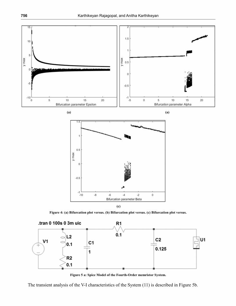
b. Bifurcation
By fixing and varying, the new system (12) is investigated. The bifurcation diagram is shown in figure
4(a).
By fixing and varying the bifurcation is investigated and shown in figure 4(b). By fixing and varying
the bifurcation is investigated and shown in figure 4(c). Generally speaking, when the system’s biggest
Lyapunov exponents is large than zero, and the points in the corresponding bifurcation diagram are dense,
the chaotic attractor will be found to exit in this system. Therefore, From the Lyapunov exponents and
bifurcation diagrams in figure 4(a), 4(b) and 4(c) a conclusion can be obtained that chaos exit in the fourth
order memristor system when selecting a certain range of parameters.
3. SPICE MODEL OF THE FOURTH ORDER MEMRISTOR
SYSTEM
The fourth order memristor system discussed in the paper is implemented as a Spice Model.The Spice
circuit model of the fourth order Memristor chaotic circuit is shown in Figure 5a.
Figure 3: Lyapunov exponents of the System (12).
756 Karthikeyan Rajagopal, and Anitha Karthikeyan
Figure 4: (a) Bifurcation plot versus. (b) Bifurcation plot versus. (c) Bifurcation plot versus.
(a) (a)
(c)
Figure 5 a: Spice Model of the Fourth-Order memristor System.
The transient analysis of the V-I characteristics of the System (11) is described in Figure 5b.
Chaos Suppressionfor a Fourth Order Memristor Chaotic Oscillator with Uncertain Parameters 757
4. LABVIEW IMPLEMENTATION OF THE FOURTH ORDER MEMRISTOR SYSTEM
The Fourth order memristor system (11) is implemented in LabVIEW using the control and simulation
tools. The control and simulation loop is used to implement the memristor system.
Figure 5b: Plot of Current V/S Voltage at ù = 10 rad/s. The M-efficiency factor (ROFF
/RON
) is considered as 160.
Figure 6: Block Diagram of the Fourth order Memristor in LabVIEW
758 Karthikeyan Rajagopal, and Anitha Karthikeyan
Figure 6 shows the block diagram of the fourth order memristor system in LabVIEW. Figure 7 shows
the 3D state space analysis of the fourth order memristor system.
5. ADAPTIVE STABILIZATION OF THE FOURTH ORDER MEMRISTOR DYNAMICS
In this section, we use adaptive control method to derive an adaptive feedback control law for globally and
exponentially stabilizing the fourth order memristor system with unknown parameters.
2
x
y
z
w
x y u
y z y x y u
z y z w u
w z w u
(13)
In (13), , , ,x y z w are the states and , , ,x y z wu u u u are adaptive controls to be determined using estimates
ˆ ˆˆ ˆˆ ˆ ˆ( ), ( ), ( ), ( ), ( ), ( ), ( )t t t t t t t and ˆ ( )t for the unknown parameters.
We consider the adaptive control law defined by
1
2
2
3
4
ˆˆ ˆ
ˆ ˆ ˆ
ˆ ˆ
x
y
z
w
u y k x
u z y x y k y
u y z w k z
u z w k w
(14)
where 1 2 3 4, , ,k k k k are positive gain constants.
Substituting (14) into (13), we get the closed-loop plant dynamics as
Figure 7: 3D State portraits of the Fourth order Memristor System in LabVIEW
Chaos Suppressionfor a Fourth Order Memristor Chaotic Oscillator with Uncertain Parameters 759
1
2
2
3
4
ˆˆ ˆ( ) ( ) ( )
ˆ ˆ ˆ( ) ( ) ( )
ˆ ˆ( ) ( )
x k x
y z y x y k y
z y z w k z
w z w k w
(15)
The parameter estimation errors are defined as
( ) ( ), ( ) ( )
( ) ( ), ( ) ( )
( ) ( ), ( ) ( )
( ) ( ),
ˆ ˆ
ˆ ˆ
ˆ ˆ
ˆ ˆ( ) ( )
e t t e t t
e t t e t t
e t t e t t
e t t e t t
(16)
we can simplify the plant dynamics (16) as
1
2
2
3
4
x k x
y e z e y e x y k y
z e y e z e w k z
w e z e w k w
(17)
We use adaptive control theory to find an update law for the parameter estimates.
We consider the quadratic candidate Lyapunov function defined by
2 2 2 2 2 2 2 22 2 2 2
( , , , , , , , , , , , )
1
2
V x y z w
x y z w e e e e e e e e
(18)
In view of (18) the parameter update law is defined as follows.
2
2 2
2
2
( ) , ( )
( ) , ( )
( ) ,
ˆˆ
ˆˆ
ˆ ˆ ( )
( ) ,ˆ ( )ˆ
t zy t y
t x y t zy
t z t wz
t zw t w
(19)
Theorem. The novel 3-D chaotic system (13) with unknown system parameters is globally and
exponentially stabilized for all initial conditions 3(0)x R by the adaptive control law (14) and the parameter
update law (19), where 1 2 3, ,k k k are positive gain constants.
Proof. We prove this result by using Lyapunov stability theory [73].
We consider the quadratic Lyapunov function defined by (18), which is positive definite on R7.
760 Karthikeyan Rajagopal, and Anitha Karthikeyan
By substituting the parameter update law (19) into (18), we obtain the time derivative of V as
2 2 2 2
1 2 3 4V k x k y k z k w (20)
From (20), it is clear that V is a negative semi-definite function on R7.
Thus, we conclude that the state vector x(t) and the parameter estimation error are globally bounded, i.e.
, , , , , , , , , , ,T
x y z w L
We define 1 2 3 4min , , , .k k k k k Thus, it follows from (20) that
2( )V k t x (21)
Thus, we have
2( )k t V x (22)
Integrating the inequality (22) from 0 to t, we get
2
0
( ) (0) ( )
t
k d V V t x (23)
From (23), it follows that 2.x L Using (28), we can conclude that .x L
Using Barbalat’s lemma [73], we can conclude that ( ) 0t x exponentially as t for all initial
conditions 3(0) .x R
This completes the proof.
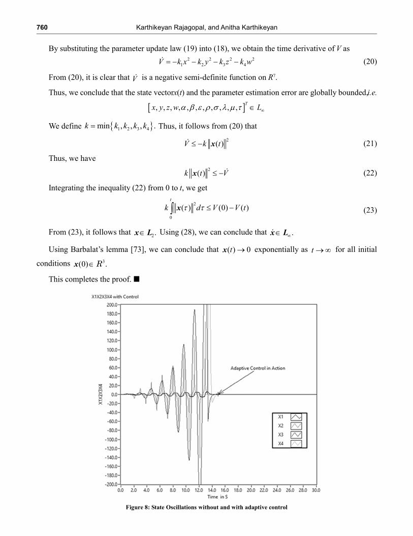
Figure 8: State Oscillations without and with adaptive control
Chaos Suppressionfor a Fourth Order Memristor Chaotic Oscillator with Uncertain Parameters 761
Figure 8 shows the state oscillations without and with adaptive controller. The controller is introduced
at t = 14s and its can be clearly seen from Figure 8 that after the introduction of the controller, the chaotic
oscillations of the states are suppressed.
6. CONCLUSION
This paper has introduced a hyperchaotic memristor oscillator system and presented a novel control method
using adaptive scheme to drive two memristor oscillator systems to synchronize the first response of the
oscillator with its second version. The resulting hyperchaos synchronization via adaptive combination
scheme is also veriûed by SPICE modelling and LabVIEW Simulations. It is believed that the derived
results and analytical techniques have great potential in controlling various hyperchaotic systems and
hyperchaotic circuits, which open up a wide area for further research of chaos and hyperchaos memristive
dynamics.
REFERENCES
[1] Chua, L. O. Memristor - the missing circuit element, IEEE Trans. Circuit Theory, 18, 1971, 507–519.
[2] Ketaki Kerur, A Study of The Memristor- The Fourth Circuit Element, M.Sc, project report for Visvesvaraya Technological
University, 2010
[3] Strukov, D. B., Snider, G. S., Stewart, D. R. & Williams, R. S. Nature, 453, 2008, pp.80–83
[4] O. Kavehei, A. Iqbal, Y.S.Kim, K.Eshraghian, S. F. Al-Sarawi, Andd. Abbott, The fourth element: characteristics, modeling
and electromagnetic theory of the memristor, Proc. R. Soc. A, 2010.
[5] L. Chua and S.M. Kang, “Memristive Device and Systems,” Proceedings of IEEE, Vol. 64, no. 2, 1976, pp. 209-223.
[6] Z. Biolek, D. Biolek, V. Biolková, “Spice Model of Memristor with Nonlinear Dopant Drift”, Radio engineering, vol. 18,
no. 2, 2009, pp. 210-214.
[7] Yogesh N Joglekar and Stephen J Wolf, “The elusive memristor: properties of basic electrical circuits”, European Journal
of Physics, vol. 30, 2009, pp. 661–675.
[8] Robinson E. Pino, Kristy A. Campbell, Compact Method for Modeling and Simulation of Memristor Devices, Proceeding
of international Symposium on Nanoscale Architecture, 2010, pp.1-4.
[9] Rak and G. Cserey, “Macromodelling of the memristor in SPICE,” IEEE Trans. Computer.-Aided Design Integr. Circuits
Syst., vol. 29, no.4, Apr. 2010, pp. 632–636.
[10] Z. Biolek, D. Biolek and V. Biolková, “SPICE model of memristor with nonlinear dopant drift”, Radio Eng., vol. 18, no.
2, Jun. 2009, pp. 210–214.
[11] D. Batas and H. Fiedler, “A memristor SPICE implementation and a new approach for magneticflux-controlled memristor
modeling”, IEEE Trans. Nanotech., vol. 10, no. 2, Mar. 2011, pp. 250–255.
[12] S. Benderli and T. A. Wey, “On SPICE macromodelling of TiO2 memristor”, Electron. Lett., vol. 45, no. 7, Mar. 2009,
pp. 377–379.
[13] Merrikh-Bayat, Farnood, and Saeed Bagheri Shouraki. “Memristor crossbar-based hardware implementation of fuzzy
membership functions.” Fuzzy Systems and Knowledge Discovery (FSKD), 2011 Eighth International Conference on.
Vol. 1. IEEE, 2011.
[14] Karel Zaplatilek, Memristor modeling in MATLAB and Simulink, Proceedings of the European Computing Conference,
2010, pp. 62-67
[15] Yogesh N Joglekar and Stephen J Wolf, The elusive memristor: properties of basic electrical circuits, Eur. J. Phys.30(2009)
661–675
[16] S.W.Keemink, Mimicking synaptic plasticity in memristive neuromorphic systems, Life Sciences Graduate School,
University of Utrecht, Utrecht, Netherlands, 2012
[17] B. Muthuswamy and P. P. Kokate, “Memristor-based chaotic circuits,” IETE Tech. Rev., vol. 26, no. 6, pp. 417–429, Dec.
2009.
[18] M. Itoh and L. O. Chua, “Memristor oscillators,” Int. J. Bifurcation Chaos, vol. 18, no. 11, pp. 3183–3206, Nov. 2008.
[19] J. Borghetti, Z. Y. Li, J. Straznicky, X. M. Li, D. A. A. Ohlberg, W. Wu, D. R. Stewart, and R. S. Williams, “A hybrid
nanomemristor/transistor logic circuit capable of self-programming,” in Proc. Nat. Acad. Sci., 2009, pp. 1699–1703.
762 Karthikeyan Rajagopal, and Anitha Karthikeyan
[20] Neil D. Mathur, The fourth circuit element, Nature, Vol 455, 30, 2008, doi:10.1038/nature07437
[21] Vongehr, S. (2012). The Missing Memristor: Novel Nanotechnology or rather new Case Study for the Philosophy and
Sociology of Science?. arXiv preprint arXiv:1205.6129. p.10
[22] R. Waser, M. Aono: “Nanoionics-based resistive switching memories.” Nature Materials 6, 833-840 (2007)
[23] Y. V. Pershin, M. Di Ventra: “Spin memristive systems: Spin memory effects in semiconductor spintronics.” Phys. Rev. B
78, 113309 (2008)
[24] Meuffels, P., & Soni, R. (2012). Fundamental Issues and Problems in the Realization of Memristors. arXiv preprint
arXiv:1207.7319
[25] Jagdish Kumar, Memristor- why do we have to know about it?, IETE technical review, vol-26, issue -1, 2009, pp.3-6
[26] Prodromakis, T., and C. Toumazou. “A review on memristive devices and applications.” Electronics, Circuits, and Systems
(ICECS), 2010 17th IEEE International Conference on. IEEE, 2010, pp. 936-939.
[27] Eshraghian, K.; Kyoung-Rok Cho; Kavehei, O.; Soon-Ku Kang; Abbott, D.; Sung-Mo Steve Kang; “Memristor MOS
Content Addressable Memory (MCAM): Hybrid Architecture for Future High Performance Search Engines,” IEEE
Transactions on Very Large Scale Integration (VLSI) Systems, vol.19, no.8, Aug. 2011, pp. 1407-1417.
[28] Erokhin, T. Berzina, A. Smerieri, P. Camorani, S. Erokhina, and M. Fontana, “Bio-inspired adaptive networks based on
organic memristors,” Nano Communication Networks, vol. 1, no. 2, 2010, pp. 108 – 117.
[29] S. H. Jo, T. Chang, I. Ebong, B. B. Bhadviya, P. Mazumder, and W. Lu, “Nanoscale memristor device as synapse in
neuromorphic systems”, Nano Lett., vol. 10, pp. 1297–1301, 2010
[30] Hu, J., & Wang, J. Global uniform asymptotic stabil-ity of memristor-based recurrent neural networks with time delays.
In: 2010 International Joint Conference on Neural Networks, IJCNN 2010, Barcelona, Spain, pp. 1-8, (2010).
[31] H.K. Khalil, Nonlinear Systems, 3rd edition, Prentice Hall, New Jersey, USA.
[32] Ailong Wu “Compound synchronization of fourth-order memristor oscillator” Advances in Difference Equations 100,
1687-1847 (2014).