UNCLASSIFIED AD NUMBER LIMITATION CHANGES TO: FROM: AUTHORITY THIS PAGE IS UNCLASSIFIED AD288136 Approved for public release; distribution is unlimited. Distribution authorized to DoD only; Test and Evaluation; AUG 1962. Other requests shall be referred to Army Springfield Armory, Attn: SWESP-PRD, Springfield, MA. 6 aug 1965, springfield armory ltr
Transcript
UNCLASSIFIED
AD NUMBER
LIMITATION CHANGESTO:
FROM:
AUTHORITY
THIS PAGE IS UNCLASSIFIED
AD288136
Approved for public release; distribution isunlimited.
Distribution authorized to DoD only; Test andEvaluation; AUG 1962. Other requests shall bereferred to Army Springfield Armory, Attn:SWESP-PRD, Springfield, MA.
6 aug 1965, springfield armory ltr
AD- 088 /3<o
RIA-77-U97 SPRINGFIELD ARMORY TfSA
YL
SPRINGFIELD, MASSACHUSETTS
RESEARCH AND DEVELOPMENT
111 USADACS Technical Library
5 0712 01013667 8
Report; SA-TR20-9209
Date; 8 August 1962
OCMS Code; 5110.22.01202
Report Title; Helicopter Accuracy Study
Authors £?. %/. W£LUa£S££!& Approved A. H. LaRlviere /^/"H* F# HAWTH0RME
Mathematician /*( Chief, Res and lfav Dlv
J//R. MayeiT M^ch Engr
1 -''5
MOB) Pom 722 7 Apr 60
•
' :><>
The findings in this report are not to be construed as an official Department of the Army position.
ASTIA AVAILABILITY NOTICE. U. S. Military installations may obtain copies of this report directly from ASTIA. Other qualified ASTIA users should request through Commanding Officer, Springfield Armory, ATTN: SWESP-PRD, Springfield, Mass.
Report; SA-TR20-9209
Date; 8 August 1962
Report Title; Helicopter Accuracy Study
Authors: C&. *M<&6*d*<a/^ Approved; J,
f A. H. LARIVIERE Mathematician
yjH. F. HAWTHORNE </vQ Chief, Res and
R. MAYER <f ech Engr
. O'NEIL Math
preparing Agency; Springfield Armory, Springfield, Massachusetts
CMS Code;
DA Project;
DA Project Title;
5110.22.01202
502-05-010
Suppressive Fire Capabilities for Army Helicopter (Quad)
This Technical Report, to the extent known, does not contain any patented material, trade secrets, copyrighted and/or copyrlghtable material, trade marks, or trade names.
RESTRICTION OF REDISTRIBUTION. This is a limited distribution report. Initial recipients shall not make any redistribution.
LIMITATION OF REPRODUCTION. Reproduction of this document, in whole or in-part, is prohibited except with permission of the originating office.
DISPOSITION: Destroy. Do not return.
REPORT SA-TR20-9209
ABSTRACT
A study was made to determine the accuracy of the XM153 (Quad) armament subsystem. Target acquisition and tracking capabilities of this subsystem were compared with those (results) presented in the referenced report. Basic accuracy of the 7.62mm M73 machine gun fired from the HU-lA helicopter equipped with the XM153 arma- ment subsystem was determined. Also, basic accuracy of the 7.62mm M60 machine gun fired from the H-13H helicopter equipped with the XM2 armament subsystem was determined. Recommendations were made for Improvement of the XM153 armament subsystem, and for future study and evaluation of the helicopter armament program. Test procedure is described and results discussed.
CONTENTS
REPORT SA-TR20-9209
Page
Subject
Objectives
Conclusions
Recommendations
Introduction
Reference
Test Material
Procedure and Discussion
2
2
2
3
4
4
4
5
Appendices:
A - Tables (9)
B - Charts (12), Graphs (2)
C - Photographs (4)
D - Distribution
9
10
20
35
40
REPORT SA-TR20-9209
SUBJECT
Target acquisition and tracking capabilities of the XM153 (Quad) arma- ment subsystem, and accuracy determination of both subsystems (XM153 and XM2).
OBJECTIVES
The objectives of this study were as follows:
1. To check the target acquisition and tracking capabilities of the XM153 (Quad) armament subsystem and to compare these results with those pre- sented in the referenced report.
2. To determine the basic accuracy of the 7.62mm M73 machine gun fired from an HU-lA helicopter equipped with the XM153 armament subsystem.
3. To determine the basic accuracy of the 7.62mm M60 machine gun fired from an H-13H helicopter equipped with the XM2 armament subsystem.
CONCLUSIONS
The conclusions drawn from the results of this study are as follows:
1. The XM153 (Quad) armament subsystem adjustments are so sensitive that proper bore-sighting is extremely difficult, if not impossible.
2* Tolerances of the components of the XM153 (Quad) armament subsystem result in an excessive rocking action of the weapons in the elevation plane because of recoil forces during out-of-phase weapon firing.
3. Deficiencies of the subsystem, together with the M73 weapon disper- sion, indicate that this subsystem is not suitable presently for point target application.
4. Results of this test program show that the deviations in aircraft and sighting dispersion were found to be considerably greater in this test than those (deviations) given in referenced report.
5. Much larger dispersions were obtained from the weapon than from the sight as determined from, camera runs with the mount and sight synchronised.
6. Hover firing resulted in increased round-to-round dispersion of approximately 2.5 times that of ground firing.
7. Basic accuracy results of the M60 from the H-13H helicopter indi- cate that the M60 weapon should be considered for future helicopter applications.
-2-
REPORT SA-TR20-9209
RECOMMENDATIONS
The following recommendations are submitted for the improvement of the helicopter armament systems:
1. provide a ready, positive, and accurate boresight adjustment to Improve the XM153 (Quad) armament subsystem. Also, provide separate ele- vation adjustments for each mount to compensate for the difference in toler- ances between the mounts and the assemblies.
2. Conduct tests with the M60C weapons and improved XM153 subsystem on the HU-lA and HU-lB helicopters to determine the potential of this sub- system for desired tactical employment.
3* Initiate a study to determine a satisfactory method of recording the weapon line of sight during burst-firing
4* Establish accuracy requirements for air-to-ground and air-to-air roles for helicopter armament systems.
5* Conduct investigations to determine the possibility of obtaining a more stable firing platform for the HU-1 aircraft series.
6. Investigate the possibility of Improving the fire control system to minimize the effect of aircraft instability for improved air-to-air accuracy capability.
7. Conduct an investigation to determine the feasibility of a larger caliber system (20mm or larger) for the HU-1 aircraft series. Include in this investigation point and area air-to-ground capabilities as well as air- to-air capabilities.
8. Conduct accuracy evaluation of the prototype M39 weapon mount in- stalled on the H-34 helicopter. (The results of such an investigation could be applied to future development of the 20mm helicopter armament system.)
9. Conduct a study of the gun-boosted rocket system for helicopter application for both point and area target roles. Include in this study methods of reducing and controlling round impulse and its effect upon the helicopter.
10. Investigate the accuracy of the XM138 armament system used on the HU-1 helicopter series.
-3-
BEPORT SA-TR20-9209
1. INTRODUCTION
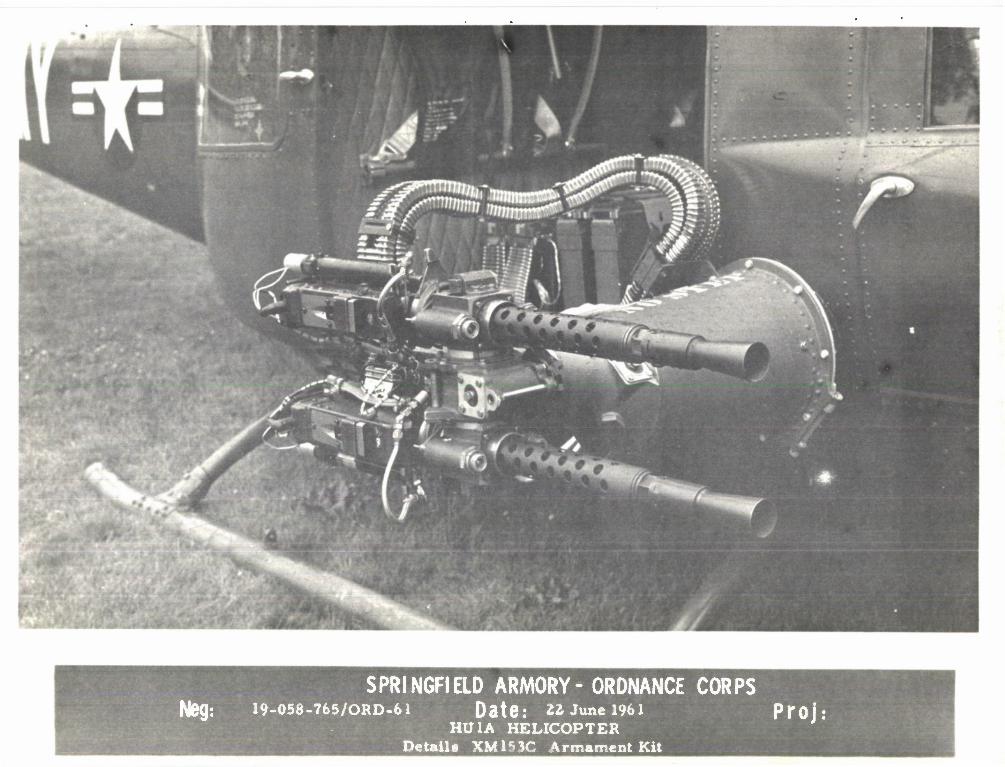
The XM153 (Quad) armament subsystem consists of two power-operated flexi- ble gun mounts, one mount on each side of the helicopter (photograph 764, Appendix C), a sighting station (No. 524525), and a control panel, as well as
solenoid-operated trigger mechanisms and hydraulic charges for each machine gun. This subsystem is more completely described in the referenced report (paragraph 2).
Because function and endurance tests of an M73 weapon were scheduled, a concurrent evaluation of the XM153 sighting system was made to verify the re- sults given in the referenced report. In addition, basic accuracy and loca- tion of center of impact relative to sighting position for various ranges and helicopter altitudes and speeds were determined. The XM153 (Quad) armament subsystem tested was a prototype and had not been designed for air-to-air point target requirements. This subsystem was used only because it was a con- venient test vehicle for the function tests of the M73 on the HU-lA helicopter. These function tests provided an opportunity to evaluate the future capabili- ties of this subsystem.
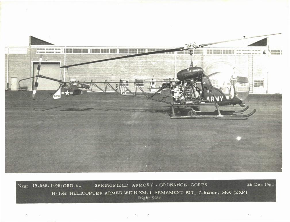
Upon completion of the M73 function tests, the HU-lA helicopter (photo- graph 764) was no longer available at the Armory. Therefore, the basic accuracy tests of the M60 machine gun were confined to the H-13H helicopter (photograph 1498) with the XM2 armament subsystem. A detailed close-up view of the two armament subsystems is shown in photograph 765 (XM153C) and photo- graph 1494 (XM2). Also Photograph 1498 is a view of the XMl armament sub- system converted from the caliber .30M37 weapon to the GPMG 7.62mm M60 weapon.
2. REFERENCE
Emerson Electric Manufacturing Company, Report 1165, "Final Report of Project HOTAC II, Helicopter Optical Tracking and control Unit".
3. TEST MATERIAL
a. HU-lA Helicopter, S/N 59-1625 b. H-13H Helicopter, S/N 58-1523 c. XM153, (Quad) Armament Subsystem d. XM2 Armament Subsystem e. AN/N6A Cameras f. Range and Target Facilities
-4-
REPORT SA-TR20-9209
4. PROCEDURE AND DISCUSSION
a. The XMI53 (Quad) armament subsystem, consisting of No. 524525 sighting system and Quad mount with four M73 mac. ,ne guns, was installed on the HU-1A helicopter. The top weapon on each of the two mounts was boresighted at a 450-yard range. Adequate boresighting of this system was not possible because of the following reasons:
(1) Adjustment sensitivity of the potentiometer settings prevented the gunner from holding the sight "on" target during the bore- sight operation.
(2) Lack of separate elevation adjustment for individual gun mounts prevented both of the top weapons from being properly bore- sighted in the elevation plane. The bias between the mounts is a constant determined by the physical dimensions and toler- ances of the weapon-mount combination. Results of the bora- sighting operation were as follows:
(a) Fairly good alignment in azimuth plane,
(b) Difference of approximately 30 feet at 450 yards in elevation between the top weapons on each mount.
(c) Notification of boresight problems to contractor.
Cameras were mounted to the sight and to the right gun mount, and two firing runs were conducted. The results of these firing runs are given in Table I, Appendix A. Because of the extremely low number of hits on a 20* X 20' target at 600 yards, an additional 1200 rounds were fired from hover at this range. Careful examination of the target cloth revealed no target hits which indicated that the sight picture was not synchronized with the line of fire.
b. At this time, the weapons were zeroed by actual firing at a 600 yard range. The results of this ground-firing confirmed the belief that either the weapons and/or the sighting system had shifted excessively. A third on- target firing run was conducted. Results obtained from the previous zeroing were used in this firing run. Only two hits resulted from the 200 rounds fired (50 rounds for each weapon).
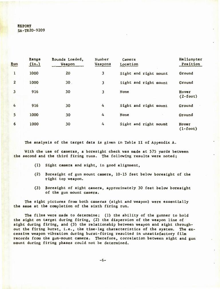
Because of the condition of the sighting system which prevented long-range target acquisition, basic accuracy of the weapon was obtained at 1000-Inch range. A sight picture was determined that allowed the rounds fired from all weapons to be recorded on two 5-foot-square targets approxi- mately 1000 Inches from the barrel muzzle. The following six firing runs were conducted;
*5-
REPORT SA-TR20-9209
Range Round8 Loaded, Number Camera Helicopter Run (in.)
1000
Weapon Weapons
3
Location
Sight and right mount
Position
1 20 Ground
2 1000 30 3 Sight and right mount Ground
3 916 30 3 None Hover (2-foot)
4 916 30 4 Sight and right mount Ground
5 1000 30 4 None Ground
6 1000 30 4 Sight and right mount Hover (1-foot)
The analysis of the target data is given in Table II of Appendix A.
With the use of cameras, a boreslght check was made at 575 yards between the second and the third firing runs. The following results were noted;
(1) Sight camera and sight, in good alignment,
(2) Boresight of gun mount camera, 10-15 feet below boreslght of the right top weapon.
(3) Boresight of sight camera, approximately 30 feet below boreslght of the gun mount camera.
The sight pictures from both cameras (sight and weapon) were essentially the same at the completion of the sixth firing run.
The films were made to determine: (1) the ability of the gunner to hold the sight on target during firing, (2) the dispersion of the weapon line of sight during firing, and (3) the relationship between weapon and sight through- out the firing burst, i.e., the time-lag characteristics of the system. The ex- cessive weapon vibration during burst-firing resulted in unsatisfactory film records from the gun-mount camera. Therefore, correlation between sight and gun mount during firing phases could not be determined.
-6-
REPORT SA-TR20-9209
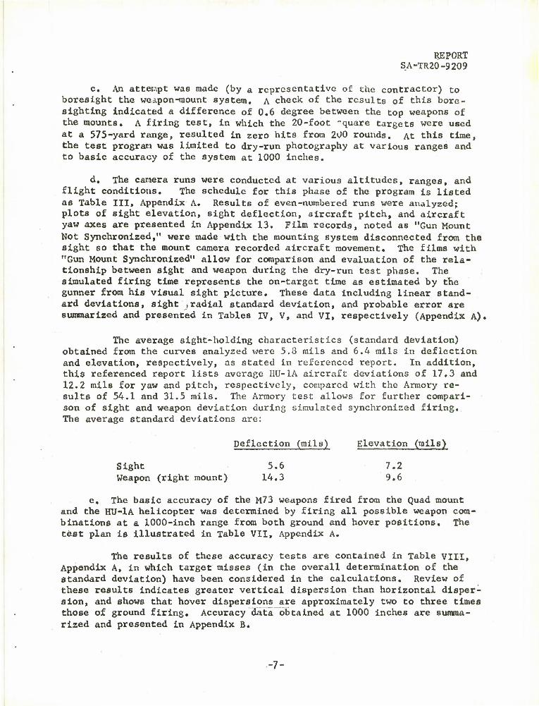
c. An attempt was made (by a representative of the contractor) to boresight the weapon-oaount system. A check of the results of this bore- sighting indicated a difference of 0.6 degree between the top weapons of the mounts. A firing test, in which the 20-foot -quare targets were used at a 575-yard range, resulted in zero hits from 200 rounds. At thiB time, the test program was limited to dry-run photography at various ranges and to basic accuracy of the system at 1000 inches.
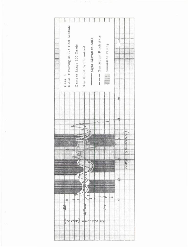
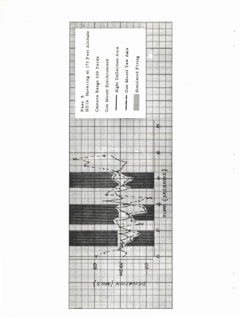
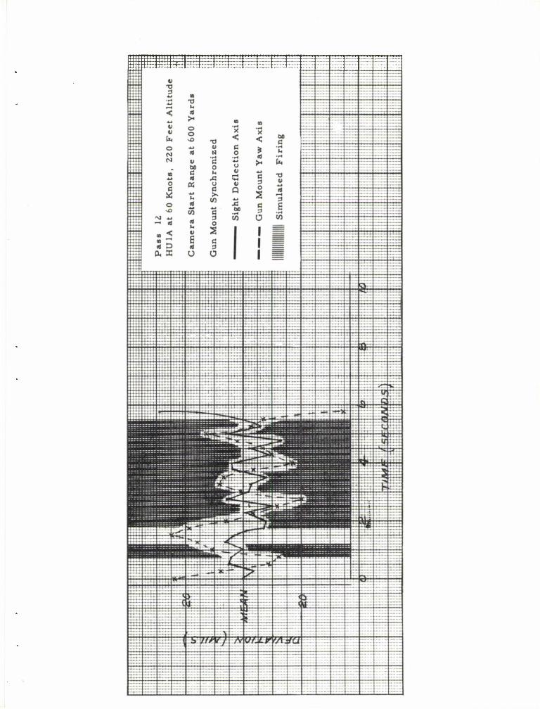
d. The camera runs were conducted at various altitudes, ranges, and flight conditions. The schedule for this phase of the program is listed as Table III, Appendix A. Results of even-numbered runs were analyzed; plots of sight elevation, sight deflection, aircraft pitch, and aircraft yaw axes are presented in Appendix 13. Film records, noted as "Gun Mount Not Synchronized," were made with the mounting system disconnected from the sight so that the mount camera recorded aircraft movement. The films with "Gun Mount Synchronized" allow for comparison and evaluation of the rela- tionship between sight and weapon during the dry-run test phase. The simulated firing time represents the on-target time as estimated by the gunner from his visual sight picture. These data including linear stand- ard deviations, sight ,radial standard deviation, and probable error are summarized and presented in Tables IV, V, and VI, respectively (Appendix A).
The average sight-holding characteristics (standard deviation) obtained from the curves analyzed were 5.8 mils and 6.4 mils in deflection and elevation, respectively, as stated in referenced report. In addition, this referenced report lists average I1U-1A aircraft deviations of 17.3 and 12.2 mils for yaw and pitch, respectively, compared with the Armory re- sults of 54.1 and 31.5 mils. The Armory test allows for further compari- son of sight and weapon deviation during simulated synchronized firing. The average standard deviations are:
Deflection (mils) Elevation (mils)
Sight 5.6 7.2 Weapon (right mount) 14.3 9.6
e. The basic accuracy of the M73 weapons fired from the Quad mount and the HU-lA helicopter was determined by firing all possible weapon com- binations at a 1000-inch range from both ground and hover positions. The test plan is illustrated in Table VII, Appendix A.
The results of these accuracy tests are contained in Table VIII, Appendix A, in which target misses (in the overall determination of the standard deviation) have been considered in the calculations. Review of these results indicates greater vertical dispersion than horizontal disper- sion, and shows that hover dispersions are approximately two to three times those of ground firing. Accuracy data obtained at 1000 inches are summa- rized and presented in Appendix 8.
REPORT SA-TR20-9209
4. PROCEDURE AND DISCUSSION - continued
f. The restricted availability of the H-13H helicopter resulted in the limited test-firing of the M60 from an XM2 armament subsystem. This subsystem provides for the installation of one MbO weapon on each side of the aircraft. The weapons were boresighted at 1000 inches and targets were obtained for both hover and ground firing at 1000 inches, and for ground firing at a 600-yard range. The following accuracy results were obtained!
Run # Range
1 1000 in.
2 1000 in.
3 600 yd.
Weapon
Left side Right side
Left side Right side
Left side Right side
Rounds Position Fired Hits 0x(mils) 0y(mil8)
Ground
Hover
Ground
30 30 1.0 0.9
30 30 9.6* 5.7* 30 30 9.6 8.0
50 50 1.1 1.6 50 12 - - - -
* Computations adjusted for target misses.
-8-
APPENDICES
A - Tables
B - Charts and Graphs
C - Photographs
D - Distribution
i
I
REPORT SA-TR20-9209
-9-
REPORT SA-TR20-9209 Appendix A
Table I. Preliminary Test Results (600 yards)
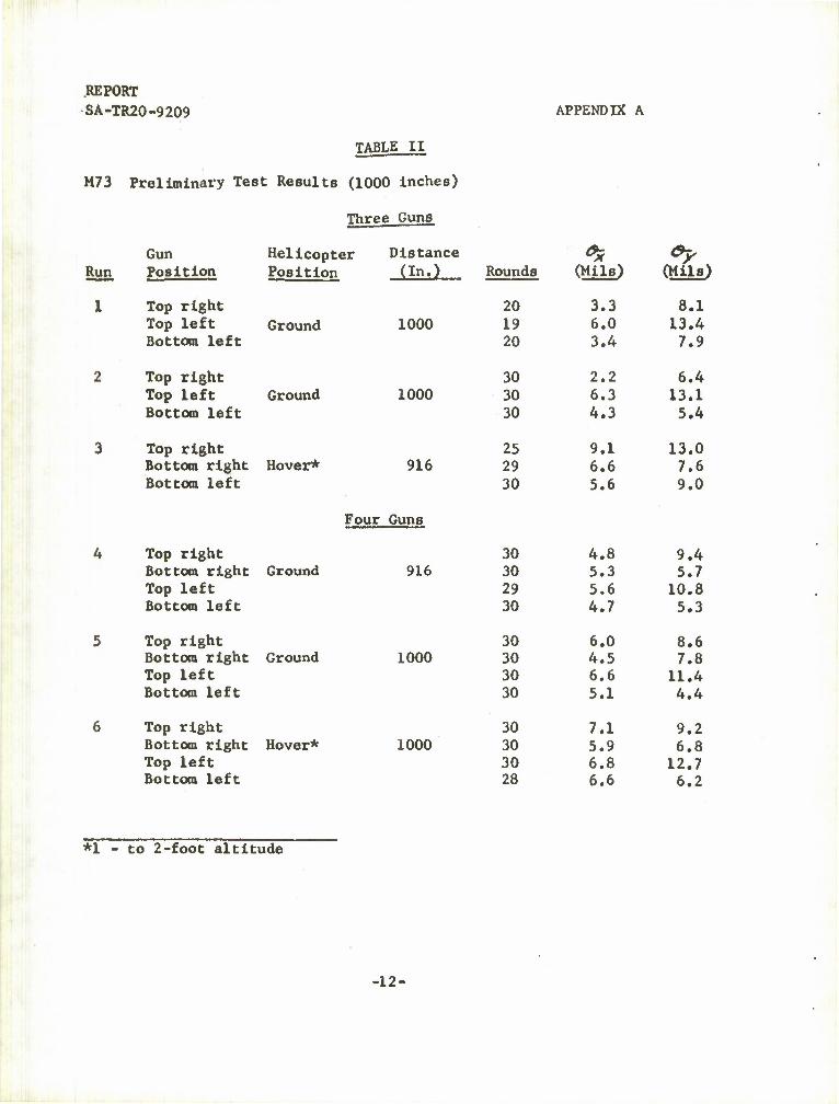
Table II. Preliminary Test Results (1000 inches)
Table III* Camera Run Schedule
Table IV. Dry Run, Camera Data
Table V. Sight Radial Standard Deviations
Table VI. Sight Probable Errors
Table VII. Target Schedule
Table VIII. Target Accuracy Data
Table IX. M73 Armament Subsystem (Mean individual weapon averages)
-10-
APPENDIX A
TABLE I
REPORT SA-TR-20-9209
M73 - Preliminary Test Results (600 yards)
Gun Location Gun Number
Top right Bottom right Top left Bottom left
383 421 292 431
Run 1 Run 2*
Range, 600 yds Altitude, 5-10 ft
Range, 575 yds Altitude, 5-10 ft
Guns No.
Rds Loaded
Rds Fired Hits
Rds Loaded
Rds Fired Hits
383 50 50 6 50 50 0
421 50 0 - 50 50 1
292 50 50 0 50 50 0
431 50 6 0 50 10 0
* Film recorded on dry run and during firing phase.
-11-
REPORT SA-TR20-9209
TABLE II
M73 Preliminary Test Results (1000 inches)
Three Guns
APPENDIX A
Gun Helicopter Distance 3? *? Run Position Position (In.) Rounds (Mils) (Mils)
1 Top right 20 3.3 8.1 Top left Ground 1000 19 6.0 13.4 Bottom left 20 3.4 7.9
2 Top right 30 2.2 6.4 Top left Ground 1000 30 6.3 13.1 Bottom left 30 4.3 5.4
3 Top right 25 9.1 13.0 Bottom right Hover* 916 29 6.6 7.6 Bottom left
Four Guns
30 5.6 9.0
4 Top right 30 4.8 9.4 Bottom right Ground 916 30 5.3 5.7 Top left 29 5.6 10.8 Bottom left 30 4.7 5.3
5 Top right 30 6.0 8.6 Bottom right Ground 1000 30 4.5 7.8 Top left 30 6.6 11.4 Bottom left 30 5.1 4.4
6 Top right 30 7.1 9.2 Bottom right Hover* 1000 30 5.9 6.8 Top left 30 6.8 12.7 Bottom left 28 6.6 6.2
*1 - to 2-foot altitude
•12-
APPENDIX A REPORT
6A-TR20-9209
TABLE III
CAMERA RUN SCHEDULE
(Cameras mounted on sight and on right gun mount)
Run Gun Mount Synchronized Hover
Camera Start (range, yds.)
Helicopter Velocity (knots)
Camera Run Time (sec.. approx.)
Altitude (ft.)
1 NO YES 600 0 15 220
2 NO YES 600 0 15 220
3 NO YES 300 0 15 20
4 NO YES 300 0 15 20
5 NO NO 600 60 -- 225
6 NO NO 600 60 -- 225
7 YES YES 600 0 15 175
8 YES YES 600 0 15 175
9 YES YES 300 0 15 20
10 YES YES 300 0 15 20
11 YES NO 600 60 ••» 225
12 YES NO 600 60 __ 225
-13-
REPORT SA-TR20-9209
TABLE IV
M73 Quad Subsystem, HU-1A Helicopter
Dry Run, Camera Data
APPENDIX A
* o g
<a 1-1 T-t (4 4J U a) cd <d <n
, I
CJ > 0) Q
CO
u
I E co
J3 . 1-1 • i-t **k 60 TJ •^ •o H • 4J ^ CO CO 5 4J
co 5 "O Pn 4J *-N u a I— M CO •w M m t> o c •U -ri u >» o o a •
o <1) CO ft 0) /-s •u o i4 z u 2 rrj Q)
M 00 > CO u 0J 4 •0 CO o <D •^ <o a • o r* > 1 > •u