UNCLASSIFIED AD NUMBER LIMITATION CHANGES TO: FROM: AUTHORITY THIS PAGE IS UNCLASSIFIED AD885922 Approved for public release; distribution is unlimited. Distribution authorized to U.S. Gov't. agencies only; Proprietary Information; MAY 1971. Other requests shall be referred to Naval Civil Engineering Laboratory, Port Hueneme, CA 93043. usncbc ltr, 24 oct 1974
Transcript
UNCLASSIFIED
AD NUMBER
LIMITATION CHANGESTO:
FROM:
AUTHORITY
THIS PAGE IS UNCLASSIFIED
AD885922
Approved for public release; distribution isunlimited.
Distribution authorized to U.S. Gov't. agenciesonly; Proprietary Information; MAY 1971. Otherrequests shall be referred to Naval CivilEngineering Laboratory, Port Hueneme, CA 93043.
usncbc ltr, 24 oct 1974
XI
00 00
3
Technical Note N-1162
ELECTROMAGNETIC INTERFERENCE (EMI) STUDY OF SIX TYPICAL ARMY
PORTABLE 3 KW ENGINE-GENERATOR SETS
By
O O
i u
S\ nz
I c?
James L. Brooks
May 1971 ■SSä-
Distribution limited to U. S. Government agencies only; proprietarv information, May 1971. Other requests for this document must be referred to the Naval Civil Engineering Laboratory.
P&t /JwHwjt'. CaMJ q3*+3 f
;■•■*
I v
CrV
Unclassified Srctmtv Classification
DOCUMENT CONTROL DATA R&D 5ri ur-.'> ft»> ,1',ration ol title, Iwdy ol /tb^trnrl and indrmn^ . >f be tnltrrd when the overall report is rUittilied)
OBiOiN» TING 4C1 i t i (Corporal* author)
Naval Civil Engineering Laboratory Port Hueneme, California 93043
1 REPORT TITLE
»•.REPORT »CCURITV CLASSIFICATION
Unclassified
ELECTROMAGNETIC INTERFERENCE (EMI) STUDY OF SIX TYPICAL ARMY PORTABLE 3 KW ENGINE-GENERATOR SETS
* OflCRlRTlVt NOTII (Typt ol report and tnrluelve date»)
oB,m,.uTtDHiT»T,MiNTDistributlon limited to U. S. Government agencies
only; proprietary information, May 1971. Other requests for this doc ment must be referred to the Naval Civil Engineering Laboratory.
• REPORT DAT«
May 1971 (• CONTRACT OR CRANT NO
...M.OJECTNO 62-004
la. TOTAL NO OP" »»«II
64 fa NO Of Rtrs
0
TN-1162
t* OTHER REPORT NOItl (Ant »that nttmaare that mar a* atelaned thla report)
I luMUMIMttlV NOTES Ttl iRONiORIN« MILITARY ACTIVITY
ATT-
KS. Army Mobility Equipment Research & Development Center Fort Belvoir, Virginia 22060
The DOD Project Manager, Mobile Electric Power, United States Army Materiel Command, sponsored a study program to investigate the electromagnetic interference (EMI) associated with six typical, portable 3 KW engine-generator sets. ^The investigation program required that each of the six engine-generator sets be subjected to an EMI test in accordance with MIL-STD-462, EMI TEST PROCEDURES. Once the EMI has been measured, suppression techniques were developed and the unit remeasured to verify conformance to MIL-STD-461, EMI SPECIFICATION LIMITS.
The test data, test techniques, test equipment, specification requirements and necessary suppression procedures are detailed in this report.
DD ,'r..1473 4/S 0»0t. »0». fciOl
(PAGf U Unclassified
S»cutitv CUvtifiraticM»
V ELECTROMAGNETIC INTERFERENCE (EMI) STUDY OF SIX TYPICAL ARMY PORTABLE 3 KW ENGINE-GENERATOR SETS
Technical Note N-1162
62-004
by
J^mes L. Brooks
ABSTRACT
The DOD Project Manager, Mobile Electric Power, United States Army Materiel Command, sponsored a study program to investigate the electro- magnetic interference (EHI) associated with six typical, portable 3 KW engine-generator sets. The investigation program required that each of the six engine-generator sets be subjected to an EMI test in accordance with MIL-STD-462, EMI TEST PROCEDURES. Once the EMI had been measured, suppression techniques were developed and the unit remeasured to verify conformance to MIL-STD-461, EMI SPECIFICATION LIMITS.
The test data, test techniques, test equipment, specification requirements and necessary suppression procedures are detailed in this report.
r1' iw son» $r
111
Distribution limited to U. S. Government agencies only; proprietary information, May 1971. Other requests for this document must be referred to the Naval Civil Engineering Laboratory.
ii
Unclassified Security Classificaticr
v E V WORDS ROLE «V no i. e * T
Electromagnetic interference
Engines
Electric generators
Measurement
Suppression
Performance teats
DD/.T..1473 •""" (f'At.l ?)
Unclassified $•1 urtiv C'l»»»ifi< «n-.f»
t I
INTRODUCTION
The test samples used in this electromagnetic interference (EMI) study were typical engine-generator (E-G) sets procured by the Army Materiel Command through the Federal Stock Numbered (FSN) system. Procurement documents required that the E-G sets comply with MIL-E-55301 (EL) Military Specification on Electromagnetic Compatability which has since been superceded by MIL-STD-461A and 462 (Electromagnetic Interference Characteristics). Since MIL-STD-461A and 462 requires different test techniques and interference limits, retesting of the E-G sets was considered necessary to insure compliance.
MIL-STD-461A designates E-G sets as Class IIIB equipment and as such dictates that certain tests be performed in order to ascertain compliance. The sponsor, however, felt that some of the requirements were too strict for this application and ordered the following changes to MIL-STD-461A requirements:
a. Eliminate narrowband EMI tests completely.
b. Perform broadband EMI tests both conducted and radiated using automated techniques to the relaxed limits as shown in Figures 1 and 2.
c. Determine suppression measures and retrofit the E-G sets to ascertain compliance.
The study program began in early FY-71. The E-G sets listed in Table 1, complete with manuals, diagrams, and operating instructions were loaned to NCEL for use as test samples.
'**•
Table 1. Test Sample Identification
1
Test Sample Frequency
Switch Selectable
Outputs Serial Number FSN Manufacturer
A 400 Hz 117V 3<|>A,
1<J>, 220V 3*Y
U, Nb68- 3160
6115-017- 8238
Chimera Corp
B 400 Hz 117V 30A,
l<fr, 220V 3$Y
H, Nb68- 3202
6115-017- 8238
Chimera Corp
C 60 Hz 117V 3*A,
U, 220V 3*Y
1*, 06716 6115-879- 9734
J.R. Hollings- worth
D 60 Hz 117V 3*A,
U, 220V 3<f>Y
14», 06703 6115-S79- 9734
J.R. Hollings- worth
DC 28V 2 wire 05121 6115-879- 9747
J.R. Hollings- worth
F DC 28V 2 wire 05118 6115-879- 9747
J.R. Hollings- worth
A casual observation of the test sample E-G sets revealed that they all had the same type of gasoline engine equipped with EMI suppression harnesses and shielded ignition wiring. Figure 3 shows a close-up photo of the harness installation.
TEST SET-UP
The test equipment listed in Table 2, was sent to the manufacturer for calibration prior to testing. Total measurement accuracy is +3 db. The EMI test equipment was set up in all steel, continuously welded shielding building located at NCEL. The E-C sets were mounted on a copper ground plaur supported by a 30-inch high bench. The ground pJ.ane was properly mounted to the wall of the shielded building In accordance with paragraph 4.2.1.2 of MIL-STD-462. The test instruments and each E-G set In turn was grounded to the ground plane with short bonding straps connected to the ground lugs provided by the manufacturers. The engine
ß
(0
H I—«
§
CM
0) rH
*
0) O «J r-» o o to r-* r> Q <J 1 < < 1 < 4 i < rH
25 00 rH
Z 55 O CM
2 z CM
V.
CO 1 1 1 U vO vD r^
u ja
u
00 c «0 cd
ix o ß
er «u u tu
o o o r- r^. r*»
< . 1 i K m en r-
CM rH H 1 1 1
o> o vO 00 r>» h- O o m rH m o
00 rH ? O
I 00
I I 1 vO rH rH x
rH a> Os m sy CM CM vD ON < < rH r-i m m 00 o\ CM •-> in a \V « CM CM -* m ro CM rH Q CM VÜ
£
u 2 3 u V «0
3 C
S 0
to c 00
•H 09
Q
3
N N N N N N
N N x
N X gj § S
X o O O O CM O O CM o
o cn rH rH in O cn M> rH CM 1 | 1 CM ^ i rH
N N t N N N J 1 N |
o x N N 3 S S N
s N
^ N X
rH rH in m O m I I o O rH r>. O o O rH O o o rH CM • CO CM rH CM * rH
« rH rH en rH r-i o rH
1 *n m i CM A en
| Q Q vO m ON m o> -* o m m CM «* rH 1 *» ON CU «n m rH <* CM 3c m CM <sj en en o> o\ O* SB o% o>
H CM
t
u »4
C «0
U 0 fO *J > 1A
U U
3 ü 4) (0 z Q-
0) to rH .* J Ü 0) to X CU
to •a 0 u
u to
■o •o o u
4 4 •o *0 o o
«0 ■o
o 44 4J
u u to (0 •o -Ü
o o 4J
u to •o T3 o u w
fO •o T3 o 4J W5
o M U C o
«I U 4J 4i 0 0 -H
-H CU 0-
o
X <
o u 0
3 3 c
a:
e
O u
J!
to c c
to u
■H c o u
•-4 2Q
u «I
rH
9 o u
a:
o c
r-< X
o>
c a
c 3 •I O AJ u
u a «4 1) u 4J ■o
£ u o u
£ M JC X rH o UJ to c
U 1-4
V5
0)
3C UJ
u. X >
at
J! J! 3c u u. a:
exhaust was piped through the wall of the shielded building through tight fitting steel conduit.
The load bank was located approximately five feet from the E-G set under test and consisted of commercially available heater strips mounted on a wooden frame. Each heater strip is rated 1 KW.
The load wiring was kept as short as practicable and were arranged in parailed and placed the required 5 cm above the ground plane. Figure 4 shows an overall view of the test set-up. The individual test load requirement was arranged by interconnecting the heater strips in the various combinations shown in Table 3.
60 or 400 hz 1$, 240V, 2 wire @ 3KW 2 parallel 2 parallel in series
60 or 400 hz 3$, 240V, 3 wire @ 3KW 2 parallel 2 parallel in series per phase
60 or 400 hz 34>, 120V, 4 wire @ 3KW 2 parallel 2 parallel in series per phase with neutral wire
DC 28V, 2 wire @ 3 KW All heaters in parallel
At the sponsors request, semi-automated measurements were performed using the Stoddart Autoplot Controller - APC-10B. This device performs two primary functions: one function Is to sweep the EMI receiver through the tuning band in a controlled manner while the other is to process the Intermediate Frequency (IF) information taken from the EMI meter with a peak hold and dump type of detector circuit. The informa- tion obtained is then automatically plotted on the accompanying X-Y plotter. The X-direction is proportional to the frequency of measure- ment and the Y-direction is proportional to the peak value of the measured interference. Appendix A contains representative X-Y plots for the first E-G tests. Because of this type of detector, the plots appear jagged, however, the peak values are correct and therefore represent the desired information. The detector circuit is limited in dynamic range however, approximately 30 db, which limits the magnitudes of the recordings and requires that the signal input to the EMI receiver
be adjusted to stay within the allowable 30 db dynamic range. This is accomplished with an external attenuator connected between the EMI receiver and with pick-up device. The EMI receiver was placed in its most sensitive gain position as recommended by the manufacturer. An additional external attenuator was placed between the EMI meter IF output jack and the input to the APC-10B input. This attenuator was set at the level suggested by the manufacturer for each EMI meter. The sweep speed was set at 11.2 revolutions per minute, a sweep speed acceptable for each of the EMI meters used.
The X-Y plotter settings were arranged so that each piece of graph paper contained information from four tuning bands. As each band was swept and the peak levels of interference measured, the recorded levels were bracketed with calibration signal levels by substituting a cali- bration impulse generator signal at the input to the EMI meter and resweeping the band with the EMI meter gain unchanged. The impluse generator output Is calibrated in db so that the calibration lines may be marked as an absolute level in db v/MHz. TO this level must be added the input attenuator factor used in the measurement and the pick-up device factor to arrive at the final value. The antennas used for the radiated measurements change the final units to db v/m/MHz while the current probe which is used for conducted measurements is a current sensing device and therefore its factor changes the final units to db a/MHz. The final units for each type of measurement are placed on the y (vertical) dimension of each corresponding plot and the calibration lines designated in db are used to interpolate the interference peak levels at each frequency.
The two lower frequency EMI meters have flat response characteristics across the tuning bands, while the two upper frequency meters do not. The antenna factors and current probe factors, however, are not flat across their respective frequency bands, therefore two calibration figures are attached to each calibration line. The top figure represents an average of all the factors for approximate interference level deter- mination and the bottom figure represents rhe absolute level to which the individual factors must be added to obtain the exact interference level. The conversion factors for the various pick-up devices are shown in Figures 5 through 10. The limited dynamic range of the APC-10B does not allow the specification levels to be plotted directly on the graphs when the difference between the specification level and the peaks of the interference level are separated by more than approximately 20 db. Therefore, on those bands which do not show a specification limit plotted, the limit is above the maximum vertical excursion of the plotter. When the limit is comparable to the interference level measured, the limit has been drawn on the X-Y plot«. (See Appendix A)
TEST PROCEDURE
All the EMI tests follow the same pattern of testing, that is; conducted EMI measurements are performed first with the expectation that if filtering is necessary, it would be performed prior to radiation testing. Radiated EMI testing would then be performed to determine what shielding is necessary to accomplish the desired suppression. Suppression measures are then to be performed and the test sample re tested. By this method, before and after test results may be directly compared to determine the effectiveness of the suppression techniques.
Test Sample A, 400 Hz, 3 KW Generator
The first E-G set selected for testing was one of the 400 Hz units designated as Unit A on page 2.
Conducted EMI. The conducted EMI tests were performed on this unit while it was operating at full load in the 3-phase Y configuration. Therefore, there are 4 traces per band on the X-Y plots. Where possible, the individual traces are identified as N, <J>1, 4>2 or <f>3 corresponding to the L0, Ll, L2 and L3 markings on the generator output. The X-Y plots shown in Figures A-l, A-2, A-3 and A-4 are the data taken during this test. Note that the highest trace represents the neutral lead, however, none exceed the specification limit. The data has been summarized in Figure 11. The existing filtering utilized by the manufacturer is sufficient and amounts to a 0.1 uf bypass capacitor from each phase lead and the neutral lead to the generator case. Figure 12 shows a photograph of these bypass capacitors in place. Figure 13 shows a typical conducted EMI test set-up.
Radiated EMI. The radiated EMI tests were performed using the antennas specified in MIL-STD-461A for each of the EMI meters available. The antennas were positioned 1 meter from the test sample directly in front of the control panel. Two readings were taken per band, one without the E-G set running (ambient) and one with the E-G set running. The biconical antenna however (20-200 MHz) required both vertical and horizontal polarization readings and ambients, therefore in this frequency range, 4 traces were taken.
The results of this test are shown in Figures A-5, A-6, A-7, A-8 and A-9 and are summarized in Figure 14. It is interesting to note that the first out-of-specification condition occurred at 300 MHz and above. The most serious out-of-specitication condition occurred between 300 and 600 MHz. A search loop was connected to the input of the EMI meter and Mie entire E-G set was search at very close quarters for the source of the offending EMI. The front of the engine section demonstrated the highest level of EMI concentrating in the vicinity of the contact points housing. As a result, the shielding effectiveness of the ignition
system was determined to be deficient. This result was a little unexpected since the engine was equipped with an ignition shielding harness.
Suppression Required. The snap cover of the contact points housing, mounted on the front of the engine, was removed and examined for possible leakage holes. A close examination revealed that the existing gasketing, a soft metal gasket intended for EMI shielding, had been glued in place, presumably to aid in maintenance work. The result of the gluing was to violate the metal to metal contact around the periphery of the cover thereby reducing the shielding effectiveness. Figure 15 is a photograph of the points housing cover showing the gasketing partially peeled back.
The gasket was removed, both it and the cover plate were cleaned and then reassembled on the E-G set. The 300 MHz to 600 MHz band was retested for radiated EMI and still demonstrated an out-of-specification condition. However, a slight improvement was noticed. Since the points housing cover is held on by two spring snaps, the two spring snaps were suspected of not providing sufficient peripheral force to effectively shield the points circuitry. Consequently, a new gasket was made from a piece of 1/8 inch thick commercial wire mesh shielding material with a rubber support (adhesive) edge which should provide a better peripheral metal to metal contact resulting from the increased spring snap pressure. Figure 16 is a photograph of the points housing cover with the new gasket attached.
Retesting. Test Sample A was retested with the new gasket in place and this time demonstrated an in-specification condition as shown in Figure A-10 and again summarized in Figure 17. As a matter of interest, the area around the front of the E-G set was again searched with the test loop and again demonstrated a high concentration of . radiated EMI, however, the E-G set had been suppressed to within the limits of accuracy to the specification desired, so it was set aside so that the test program could continue.
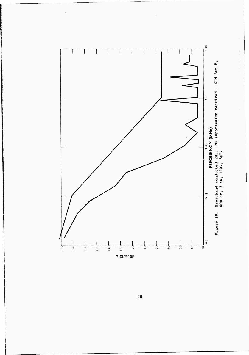
Test Sample B, 400 Hz, 3 KW Generator
The sponsor, specifically requested that all possible load configurations of one of the 400 Hz units be checked for conducted EMI, therefore, Generator B was selected for this test.
Conducted EMI. The different load configurations were as follows:
Mode 1: 120V, 4 wire, 3$Y. The test results are summarized in Figure 18. The conducted EMI did not exceed the specification level for any of the four wires.
Mode 2: 240 V, 3<f>A. The test results are summarized in Figure 19. The conducted EMI did not exceed the specification level for any of the three wires.
Mode 3: 240V, l<j>. The test results are summarized in Figure 20. The conducted EMI did not exceed the specification level in either of the two wires.
Mode 4: 120V, 1$. The test results are summarized in Figure 21. The conducted EMI did not exceed the specification level in either of the two wires.
Radiated EMI. The radiated tests were performed on Test Sample B in exactly the same manner as Test Sample A, with very similar results. The results of this test have been summarized in Figure 22. Again the out-of-specification condition occurred at the high frequencies, due to ignition interference (see Figure 14). The source of the offending interference was again traced with the small loop as described for Generator A, with exactly the same results.
Required Suppression. The first attempt at suppressing the ignition interference was identical to that performed on Generator A. The points housing cover was removed and cleaned, the gasket was replaced and the unit was retested. It was discovered, however, that this suppression was not enough. The front of the engine still demonstrated considerable radiated interference when searched with the test loop.
The engine-generator was then removed from the test bench and the ignition coil housing cover was removed, see Figure 23. Here again the existing gasketing has been glued in place and thereby violated the metal to metal contact necessary for effective shielding. In addition, the drive pulley shaft hole seemed much larger than necessary. This hole was the source of the interference leakage from the coil housing.
The proper suppression of the coil housing therefore required the cleaning of the gasket and mating surfaces as well as filling the hole surrounding the pulley shaft when the cover is replaced. As an expedient, the hole was plugged with the same material used to form a gasket on the points housing cover, see the sample shown in the bottom of Figure 16. The rubber backing has an adhesive material attached so that the gasket may be readily bent into the required shape and glued in place. The new gasket was formed to cause metal to metal contact between the pulley shaft and the inside of the hole in the coil housing cover.
The cover was bolted back in place, the engine-generator was placed back on the test bench and retesting at the high frequencies resumed. The suppression described was effective in suppressing the interference, however, it was discovered that when the engine gets hot, the glue melts and the gasket in the pulley shaft hole comes out. Therefore, a mechanical method of attaching the gasket was worked out as shown in Figure 24.
Retesting. Test Sample B was then retested completely for radiated EMI with the results summarized in Figure 25. Conformance with the limits of MIL-STD-461 was then assured. As a precaution, Generator A was retrofitted with a pulley hole gasket in the same manner although it had passed the specification limit.
Test Sample C, 60 Hz, 3 KW Generator
The 60 Hz engine-generators were also equipped with switch selectable multiple output configurations identical to the 400 Hz sets. Since the power rating was the same, the same load was used to conduct the tests.
Conducted EMI. The conducted EMI test on Test Sample C was performed while the unit was operating in the 120V, 3<j>Y mode. The results are summarized in Figure 26. Again, the neutral lead demon- strated the highest EMI level. The conducted interference was within the specification limits. The generator output lugs were marked the same as the 400 Hz units had been, however, the 60 Hz units were equipped with additional parallel outputs in the form of a standard 3 prong plug. See Figure 27. The existing filtering which consists of a . lyf capacitor from each phase including neutral to chassis proved adequate in meeting the suppression required.
Radiated EMI. The radiated EMI test proceeded in the same manner as described for the previous generators. Again, the engine demon- strated the out-of-specification condition at the higher frequencies, as summarized in Figure 28.
Required Suppression. Both the points housing cover and the coil housing cover were removed and cleaned. A new RFI gasket was installed on the points housing cover and filler gasket was installed in the shaft hole of the coil housing. Both covers were then replaced for verification testing.
Retesting. The radiated EMI was remeasured on the suppressed Test Sample C with the results summarized in Figure 29. The suppression proved to be adequate.
Test Sample D, 60 Hz 3 KW Generator
The test procedure for this generator followed the same pattern as for the others, with minor variations. First, the conducted EMI was measured for all possible load configurations and second, the radiated tests were performed at the prescribed 1 meter distance and then repeated at the requested 6 meter distance.
Conducted EMI. The different load configurations are as follows:
Mode I: 120V, 4 wire, 3$Y. The test results are summarized in Figure 30. The conducted EMI did not exceed the specification limit for any of the four wires
Mode 2: 240V, 3$A. The test results are summarized in Figure 31. The conducted EMI did not exceed the specification level for any of the three wires.
Mode 3: 240V, 1$. The test results are summarized in Figure 32. The conducted EMI did not exceed the specification level in either of the two wires.
Mode 4: 120V, 1$. The test results are summarized in Figure 33. The conducted EMI did not exceed the specification level in either of the two wires.
Radiated EMI. At the sponsors request, the radiated EMI test was first performed at the normal I meter antenna distance and then repeated at 6 meter antenna distance. The tests were run and recorded on the same graph paper and are summarized in Figure 34. The difference in interference level was negligible, however, when a difference was observed, it was marked on the original data sheets.
Again, this test sample demonstrated the out-of-specification condition at the high frequencies due to the engine ignition.
Required Suppression. As described previously, the contact points housing cover and the coil housing cover were removed, cleaned, new EMI type gaskets provided and reassembled for retesting.
Retesting. Test Sample D was retested for radiated EMI at the standard 1 meter antenna distance with the results as summarized in Figure 35. The radiated EMI fell within the allowable limits.
Test Sample E, 28V DC Generator
This unit was the first of the dc generactors, therefore, the load bank had to be modified so that the required full load current could be delivered for the duration of the test. The load bank modification was accomplished by paralleling heater strips until full load current as indicated by the panel meter was observed.
Conducted EMI. The conducted EMI of the dc generator was measured on both the positive and negative leads. The results of this test are summarized in Figure 36. The conducted EMI did not exceed the allow- able specification limits.
10
Radiated EMI. The radiated EMI was measured in the same manner as described previously with the same results, excess interference at the higher frequencies. The results are summarized in Figure 37.
Required Suppression. The now standard procedure of providing new gaskets for the points housing cover and coil housing cover was imple- mented and the engine reassembled for verification testing.
Retesting. The results of retesting Test Sample E are summarized in Figure 38. The suppression technique was effective.
Test Sample F, 28V DC Generator
The test procedure for Test Sample F was the same as for the previous unit, with largely the same results.
Conducted EMI. The test procedure and test results for the conducted EMI were similar to those previously described for Test Sample E. The results are summarized in Figure 39.
| Radiated EMI. The radiated EMI test followed the same procedure as before with about the same results. The engine demonstrated an out- of-specification condition at the very high frequencies. The results
| are summarized in Figure 40.
Required Suppression. The standard suppression measures were applied to the points housing cover and the coil housing cover as
I previously described.
Retesting. The radiated EMI was remeasured with the summarized data shown in Figure 41. Again the suppression techniques proved adequate and Test Sample F now conforms to MIL-STD-461 and 462 requirements,
CONCLUSIONS
1. All conducted EMI measurements were within the specification limits, indicating that the existing filter capacitors in all the gen- erators are sufficient as is. Therefore, no change or alternation is necessary on the part of the generator manufacturers.
2. AH radiated EMI measurements demonstrated an out-of- specification condition at lUe higher frequencies identified as ignition interference.
3. Tin» sources of the offending radiated EMI were identified as poor EMI gaskets on the breaker point compartment and the ignition coil compartment of the engine.
11
4. The existing shielding hardness on the spark plug wires provided adequate EMI shielding.
RECOMMENDATIONS
1. Additional EMI suppression should be applied to all engines used as prime movers for the 3 KW class of engine-generator sets using the following procedures:
? a. Replace the existing gasket. (Identified in TM-5-2805-203-24P
as item 1 in Figure 14) U.S. Army Technical Manual with a new gasket made of 1/8-inch cross section wire mesh material.* Clue should not be applied to the mating surfaces. The new gasket can be procured with an adhesive tab attached to the edge so that the gasket may be attached to the cover plate. A sketch of this new gasket is shown in Figure 42.
b. The existing gasket, (Identified in TM-5-2805-203-24P as item 7 of Figure 16) should be installed free of any adhesive material.
c. A new annular shaped gasket formed of the new 1/8-inch cross section wire mesh material1 mounted on a copper backing plate should be supplied and installed on the cover plate of the points housing (Identifed in TM-5-2805-203-24P as item 11 of Figure 16). The purpose of this gasket is to fill the hole between the cover plate and the pulley shaft. The gasket should be attached ind bonded to the cover plate with screws. A sketch of this gasket is shown in Figure 43.
The EMI gasketing material is available under the trade name "Teckstic." It is a wire mesh material of 1/8 inch cross-section and can be procured in strips or in specific shapes as specified.
Department of the Army Technical Manual, TM-5-2805-203-24P "Organizational; DS and GS Maintenance Repair Parts and Special Tool Lists" Oct 1968.
12
^
2 § 8 zHw/v*qp
13
o o
* a o fh
0)
C eg
r •T3
5 s •— u m
u 3
s
o 8 8 S
»Hw/w/^qp
S
14
Figure 3. Close up photograph of the EMI shielding harness.
Figure 4. Overall view of test setup.
15
m CO
o CO
00
uO c-j
en CN
csj
O CM
00
^- r-<> ?s -+ O -t -? <f <f <r
UO
00 UO
^5 in
CN m
O m
oo
CM
o
oo CO
CO
CO
eo
00
>£>
00 O
O
0>
CM CJ\
CO CO
CO
o CO
00
o
lA
in CM c
i •rl
CN ^
CN CJ . c CN OJ
3 r-t or . <U CN h
1*4
O a) 3
CN 09 U 0>
O* > * i-4 w u
0 CO
vO
vO ifl ^ H N H CO CO CO CO CO
<N -H o a* oo vt «tf -» cn en
ON 00 i"*» ^O in CO CO CO CO CO
CX3 e c OJ
C fO
73 O
H m CM l
u Cfl
T3
*J
CO
4)
3 00
c 33
CN
-3
CO
■o
16
M -4 Q s>fS f» m ?5 es
m
C 00
in
m
o 00
m •
O r-
m vO
O
in
m
O
en
m
H
vO H
m
en
CM
m
m
i i-i
*tf m
o • 1-4
00 1 «-»
en m
en
en
en v* i—i
m m
CS CS
es o iH
c> m 0:
CM
iH
in
•a es
CS
O #■4
o •H
•H m
es 0>
o c*
i in
30
) r* to m «a J N N N N
CO
i 35 *8 sO
1 S3
CO r* rs e> i
1 33
CM en
o E en T.
C •H
o^ es >*
U OJ c
00 3 CM cr
0) V-
iw r-» es (A
> VJO tfl <N U
m CS
en es
CM CS
es
O es
o>
00
«9 C c 4-1
c ea
T3 0 1-
H m es
u u «9 ■o
0 4J CO
u 3 afi
4 « N -« O rs es es es es
"3 C
SO
17
\
)
n i b u *\ i 5 a "I o
o
O N <N 35
U c s cr
o 00
u 0)
cr
u
V)
U) H
s M 0 *J a tfl
C o
•H
0 <D
U o a
S a)
d to
Ü •H ß O CJ
•H CO
3
•H
o
™ qp uj aouotj uojqoaajo^ euuaauy
18
o o
o o
>. u c
cr a
M a 5M
>
o
o u r*s 4-1
C 0
N »H g 4-1 f^t u
(1) o o
c •H
s-l
^0 u
0 u
c 8J o; r. 3 c cr CD aj 4J u n
PH CT!
cd
•H a w
00 0
crj U
•r-t c 0 u
00
(U
3 00
•H
gp uj aoaasi uojSoajJOQ Fuua^uy
19
N
a c
•H
>s U C <JJ 3 cr OJ
u Ö
cr <u M
(fl a m IM 0) > V-i
o •u u eg
c o
u
o a OJ jo o u a
c u u 3 u
ON
M 3 00
•H
o = o
uiqo [ < fjp uj ajuop^duii aajsueax
o 7
20
A
o 00
m
o
m
o
m
o m
in
-a C
CO
m
O
o
B
/
CO
vX>
a (0
CQ
1 7H vO
o m rH
o >, <r U iH
a) 3
O cr CO <u H <r IM
IM o T3 Csl C en H ofl a
PC 03 U
O QJ rH > rH
o 0 o 4J rH U
IM o CTN ß
0 •H 4J
o U "5 0)
u u 0 o u
o OJ sr rH
a 0
00 u m
cd c c
vD 0J m 4-1
c CO
■$■ -a en 0 u
CM H en
CM f-t
o T3 ^ m C « 4J
CQ
00 TJ ac CM T3 Ui
c
v£5 CN
d r-4
<r <N 0>
u 3
CN &c r-j
O <N
21
ZM/^flP hi
22
Figure 12. Photograph of . Igf bypass capacitors used for conducted EMI filtering on the generator output leads.
Figure 13. Photograph of conducted EMI test setup.
N0T ««ODBCIBU
23
ZHK/<a/AnflP
24
NOT REPRODUCIBLE
X.
u 0 > 0 Ü
GO c
•H • W ^ p u 0 CO X X
CO T3 *J <U c rH
•H 0) O 0) a a u ►l Ü rH CO rH 4J crj c •H 0 u u M
crj <D a X -u 4J
a) «4-1 ^ o w
CO X 00 a CO rH u CO oo c 0 •H 4J 00 0 •H X u & 0
<r>
2 3 00
-£<•
25
NOT REPRODUCIBLE
Figure 16. Photograph of the contact points housing cover showing the new EMI shielding gasket Installed and a sample strip of the shielding material below.


!['a1w¨Ë> EMI c0 . ± c0 . Xv¾O^8Ð4< EMI Immunity …...ßP} ¿P ¨ ¿k=± EMI c0 . Ly5 U,]5 Xv¾O^8Ð4< 'a1w¨Ë> ([4>8nCMOS Xv¾O^8Ð4< ¨ ¿k=Ly5 U,]5 Xv¾O^8Ð4](https://static.documents.pub/doc/80x56/5faa729fabc0545fba225fc7/a1w-emi-c0-c0-xvo84-emi-immunity-p-p-k.jpg)


