UNCLASSIFIED AD NUMBER LIMITATION CHANGES TO: FROM: AUTHORITY THIS PAGE IS UNCLASSIFIED AD465079 Approved for public release; distribution is unlimited. Distribution authorized to DoD only; Administrative/Operational Use; JAN 1965. Other requests shall be referred to Army Materiel Command, Mohawk Project Manager's Office (AMCPM-MO), Washington, DC. USAAVSCOM ltr dtd 12 Nov 1973
Transcript
UNCLASSIFIED
AD NUMBER
LIMITATION CHANGESTO:
FROM:
AUTHORITY
THIS PAGE IS UNCLASSIFIED
AD465079
Approved for public release; distribution isunlimited.
Distribution authorized to DoD only;Administrative/Operational Use; JAN 1965. Otherrequests shall be referred to Army MaterielCommand, Mohawk Project Manager's Office(AMCPM-MO), Washington, DC.
FINAL REPORT OF THE AIRWORTHINESS CERTIFICATION TEST OF THE
QRC-lbO-1 INSTALLED ON THE OV-1C AIRPLANE
JANUARY 196 5
HEADQUARTERS
U.S. ARMY AVIATION TEST ACTIVITY EDWARDS AFB, CALIFORNIA
^^M« , .:^.ri—^v:^t^ , ^^it ^t^ . J
/^•^ DEPARTMENT OF THE ARMY HEADQUARTERS. U.S. ARMY TEST AND EVALUATION COMMAND
ABERDEEN PROVINCi GROUND. MARYLAND 21005
Äi-lS'fE-EL P-6T11-03 1 9 MAY 1955
SUBJECT: Final Report of the AlrvorthineGs Certification Teot of the QRC-l6o-l Installed on the 0V-1C Airplane, USATECOM Project Ho. 6-3-6711-03
10: Corxianding Officer U. S. Army Aviation Test Activity ATTN: STEAV-PO Edwards AFB, California 93523
Subject report has been forwarded to the Moliavk Project Manager for information and retention.
FOR THE COMMANDER:
01.;v i" K ir. A .-,r(.\ ■/ALL,, JK, -7
Cap',, A dt',
A',M Aüuun Office;
NOTICE: VJhen government or other drawings, speci- fications or other data are used for any purpose other than in connection with a definitely related government procurement operation, the U. S. Government thereby incurs no responsibility, nor any obligation whatsoever; and the fact that the Govern- ment may have formulated, furnished, or in any way supplied the said drawings, specifications, or other data is not to be regarded by implication or other- wise as in any manner licensing the holder or any other person or corporation, or conveying any rights or permission to manufacture, use or sell any patented invention that may in any way be related thereto.
U.S. ARMY AVIATION TEST ACTIVITY
"ODC AVAILABILITY NOTICE"
U. S, military agencies may obtain copies of this report directly from DDC. Other qualified users
shall request through Headquarters, U. S. Army Materiel Command, Mohawk Project Manager's Office
(AMCPM-MO), Washington, D.C,
FINAL REPORT OF THE AIRWORTHINESS CERTIFICATION OF THE
JOHN A. JOHNSTON Major, U.S. Army, TC Project Pilot
AUTHENTICATED BY:
RICHARD ■I/KENNEDY, JR, Lieutenant Colonel, 7C Com^Wi'ng
ill
_
TABLE OF CONTENTS
ABSTRACT
SECTION !. GENERAL
■-
Page
1.1 References 1.2 Author!ty 1.3 Test Objectives \.k Responsibi1i ties
1.5 Description of Materiel 1.6 Background
1.7 Find!ngs 1.8 Conclusions
1.9 Recommendations
SECTION 2. DETAILS AND RESULTS OF TESTS
SECTION 3. APPENDICES 1. Test Data
II. General Aircraft Information III. Symbols and Abbreviations IV. Photographs V. Distribution List
2 2 2 k k 16 17
I M II- IV- V-l
IV
ABSTRACT
An engineering flight evaluation to provide an Airworthiness Certification of the OV-IC airplane equipped with the QRC-160-1 Electronic Countermeasure (ECM) was conducted by the U. S. Army Aviation Test Activity (USAATA) at Edwards Air Force Base, Cali- fornia. A total of 35 flight hours was flown during this evaluation between k January \SSk and 2^ January 196^.
Recommendation for Airworthiness Certification was issued by the USAATA in Message STEAV--E 29-I-65, 30 January 1964 (Reference I.l.c).
The QRC-I60-I is an ECM External Store weighing 195 pounds used for the protection of aircraft. For this test, the installation was mounted at the drop tank station on the left wing of the OV-IC.
The (IRC-I60-I can be employed with safety when mounted on the left wing of the OV-IC with either a full or an empty 150-gallon drop tank mounted on the right wing provided that a restricted flight envelope is observed.
The results of this evaluation concurred with the recommendation by the Naval Air Test Center of an airplane center-of-gravity (C.G.) limit of 30 percent mean aerodynamic chord (MAC) rather than the Operators' Manual limit of 33 percent MAC.
Additional testing should be conducted to determine whether the lateral-directional problems uncovered during this program are inherent characteristics of OV-IC aircraft.
The Operators' Manual for the OV-IC should be updated to include single-engine performance and minimum control speeds at altitudes above sea level.
\/:-::. V '• ■ , i_ i^»S_
.•:-V':L-a
^>„-
5*3 S :j*^*;v^
Photo 1 - Mohawk 0V-1C
vi
■ '. \\^:\'ij::'f:\:-l:ii^::.::v.];''::;'■■■■-.■: .--/'■ V ''r.'av.,,-.;,:..: •■ ■
■—■
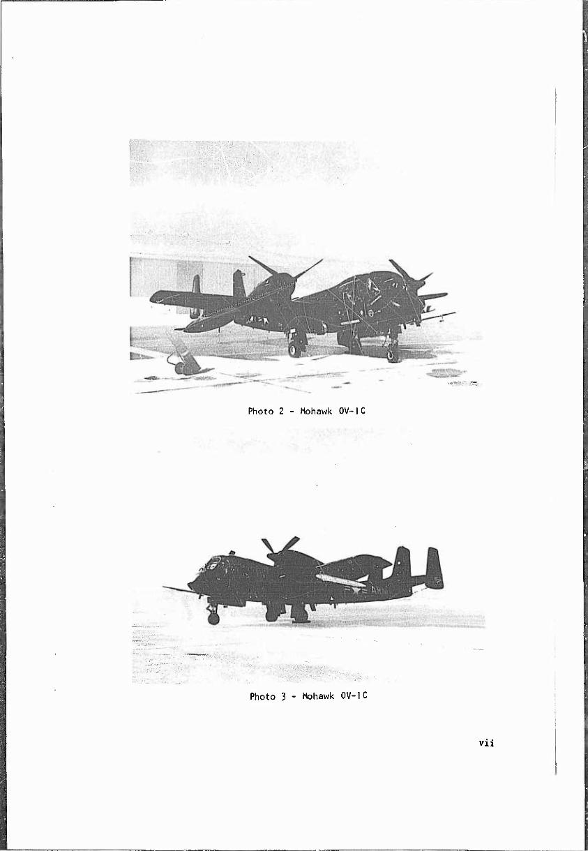
Photo 2 - Mohawk 0V-1C
Photo 3 - Mohawk 0V-1C
VXl
SECTION GENERAL
1.1 REFERENCES
a. Message TT18468, AMSTE-EL, Headquarters, U.S. Army Test and Evaluation Command (USATECOM), 2 November 1963, subject: Military Potential Test of Electronic Countermeasure (ECM) Equipment QRC-lSO-l.
b. Message TT19199, AMSTE-EL, Headquarters, USATECOM, 15 November 1963^ subject: Flight Certification Tests of the Q.RC-I6O-1 Installed on the 0V-1C Airplane.
c. Message STEAV-E 29-1-65, U. S. Army Aviation Test Activity (USAATA), 30 January 1964, subject: Flight Release of the OV-lCwith the (iRC-l60-l External Store Installed.
d. AFFTC-TN-59-21 , "AFFTC Stability and Control Techniques," U.S. Air Force Flight. Test Center (AFFTC), May 1959.
e. Military Specification MIL-F-8785 (ASG), "Flying Qualities of Piloted Airplanes," 1 September 195^.
f. Technical Manual TM-55-I510-204-10, "Operators' and Crew Members' Manual, Army Models 0V-1A, 0V-1B and 0V-1C Aircraft," Department of the Army, May 1963.
g. Report No. 1, NATO 9IS 21238, "Combined Stability and Control and Aircraft and Engine Performance Trials of the Model VAO-I Airplane," U.S. Naval Air Test Center, )] August i960.
h. Military Specification MIL-I-6115A, "Installation of Instrument Systems, Pi tot Tube Flush Static Post Operated.," 31 December i960.
i. AFFTC-TR-6273, "Flight Test Engineering Manual," AFFTC, May 1951.
1.2 AUTHORITY
a. Message TT18468, AMSTE-EL, Headquarters, USATECOM, 2 November 1963, subject: Military Potential Test of Electronic Countermeasure (ECM) Equipment (1RC-160-1 (Reference 1.1.a),
b. Message TTI9199, AMSTE-EL, Headquarters, USATECOM, 15 November 1963, subject: Flight Certification Tests of the (1RC-I60-1 Installed on the OV-IC Airplane (Reference l.l.b).
1.3 TEST OBJECTIVES
The objective of this test was to provide a recommendation for Airworthiness Certification of the ECM QRC-160-1 installed on the 0V-1C airplane for the Military Potential. Test of the System.
I.k RESPONSIBILITIES
The USAATA was assi9ned as Participating Test Authority in the Militan- Potential Test of the ECM QRC-160-1 installed on the OV-IC airplane and as such its specific responsibility was to conduct Airwortniness Certification Tests for the test program.
I.5 DESCRIPTION OF MATERIEL
1.5.1 PHYSICAL CHARACTERISTICS OF THE QRC-160-1
The only characteristics of the QRC-160-1 pertinent to this evaluation (i.e., factors influencing flying qualities) were its weight and dimensions. The QRC-lGO-l mounted on the left wing Aero 65A rack of the 0V-1C is shown in Photographs 1 and 2 (Pages vi and vii). The QRC-160-1 mounted at this station did not interfere with normal operation of the flight controls.
follows The n^rtinent physical characteristics of the Q.RC-160-1 are as
a. Weight 195 lb b. Mass Moment of Inertia
about Center of Gravity (CG.) 7?-,810 lb/in/
c. Length 93 in. d. Diameter 10.5 in.
1.5.2 PHYSICAL CHARACTERISTICS OF THE 0V-1 C
The QRC-160-1 was installed on a standard production OV-IC. The OV-IC is a two-place, twin-engine turboprop airplane, designed to operate from small, unimproved fields for purposes of tactical obser- vation. The airplane is a tricycle-gear, mid-wing, tri-tail type with engine nacelles mounted on top of the wings. The primary flight controls are unboosted and are operated by mechanical linkages with the exception of hydraulically boosted inboard ailerons that actuate with the outboard ailerons whenever the flaps are extended. The airplane is powered by two Lycoming T53-L-3 engines rated at 1005 engine shaft horsepower (ESHP) each.
The pertinent dimensions of the OV-IC are as follows:
a. Wing Span k2 ft. b. Wing Area 330 ft2
c. Maximum Length k] ft d. Static Wheel Base 11.7 ft. e. Vertical Tail Height 12.7 ft.
i .5.2.1 Control Surfaces of the 0V-1C
Pertinent details concerning control surfaces of the 0V-1C are as follows:
Control Surface
Elevator
Elevator Trim Tab
Aileron (Outboard)
Ai leron Spring Tab
Ai leron Trim Tab
Aileron (Inbo-fd)
Rudders
Combination Trim and Geared Leading Tab on the Center Rudder
Wing Flaps
Wing Slats
Speed Brakes
Deflection
25 deg Trailing Edge UP (TEU) to 15 deg Trai1ing Edge Down (TED)
7 deg TEU to 5 deg TED
25 deg TEU to 25 deg TED
15 deg TEU to 15 deg TED
15 deg TEU to 15 deg TED
k5 deg TEU from a 23 deg TED posi t ion No Down travel
25 deg Right to 25 deg Left
Trim tab travel 17 deg Right and 18 deg Left with zero rudder deflection. Geared leading tab (nonlinear) with a maximum deflection of 10 deg Right and 12 deg Left with neutral trim tab setting.
Takeoff 15 deg Down Landing kS deg Down
'0 percent chord movement Forward and 6 percent chord movement Down
0 deg or 60 deg
^
mammB—
1.6 BACKGROUND
The U.S. Army Electronic Proving Ground (USAEPG) was directed to conduct a Military Potential Test on the QRC-I60-I ECM installed on the OV-IC airplane. Prior to testing, Airworthiness Certification for the system was required. The USAATA was directed to perform such tests as were necessary for the Project Manager to issue an Airworthiness Certificat ion.
An OV-1C airplane, Serial Number 61-2699, was delivered to the USAATA on 22 November 1963. Instrumentation was accomplished. The first flight was conducted on '-i January 1964 and the airplane was delivered to the USAEPG at Fort Huachuca, Arizona, on 28 January 1964, for continuation of the QRC-I60-1 Military Potential Teüt.
Recommendation for Airworthiness Certification was issued by the USAATA in Message STEAV-E 29-1-65, 30 January 1964 (Reference 1.1.c).
1.7 FINDINGS
1.7.1 GENERAL
The philosophy employed in this evaluation was to test the QRC-160-1 installation thoroughly in one configuration inasmuch as time considerations precluded the development of a complete flight envelope. With this objective in mind, the decision was made to test the airplane with the (iRC-l60-l on the left wing and a full fuel drop tank on the right wing. This configuration was considered to be the most useful for the Military Potential Test of the system and the most critical from a stabi11ty-and- control viewpoint. Qualitative stability and control tests with the QRC-160-1 on the left wing and no external stores on the right wing verified this assumption. Unless otherwise stated, therefore, all tests and plots refer to the configuration of the QRC-160-1 on the left wing and a full fuel drop tank on the right wing.
Flight tests were conducted at an average density altitude of 7500 feet for all tests except the single-engine tests, which were conducted at a density altitude jf 5000 feet. The average takeoff gross weight for these tests was approximately 14,300 pounds and takeoff C .G. ranged between 23.3 percent mean aerodynamic chord (MAC) and 29.4 percent MAC.
All flight tests were conducted using the flight test procedures and reduction techniques outlined in Reference 1.1.d.
No jettison tests were performed during this evaluation; therefore, if the system is adopted for general Army use, jettison tests as well as tests to expand the flight envelope should be conducted. Until additional
■UMIIIH IM 1111111II11 ■HW—WIIIIH I II ——I ■
■ ■ ■ ' ■ ■ " ■■.■.-.
tests are conducted, the Q.RC-160-1 should be limited to the left wing external store station with no other external store installed than a drop tank on the right wing.
The standard of comparison used In this evaluation was MIL-F- 8785 (ASG), "Flying Qualities of Piloted Airplanes," (Reference I.l.e).
The following abbreviations are used throughout the report when referring to the various airplane configurations tested:
TABLE 1. ABBREVIATIONS FOR TESTED CONFIGURATIONS
Condi tion Symbol Trim Airspeed Flaps Landing Gear
Takeoff TO '•^stall 15° Down
Power-Apptoach PA '^ Vsta,l k50 Down
Cruise (Clean) CR 177 kts CAS Up Up
Level Flight at Normal Rated Power
NRP Velocity for Normal Rated
Power
Up Up
1.7.2 TAXIING, TAKEOFF AND INITIAL CLIMB
The airplane could be taxied with any amount of fuel in the right drop tank and with either or both engines unfeathered. The wheel brakes were effective for directional control and had to be used exten- sively when both engines were unfeathered. Asymmetric power for directional control was hazardous; and high yaw rates were encountered, particularly when returning from reverse thrust to forward thrust at high power. The rapid brake applications required to overcome these yaw rates will cause excessive tire wear. Feathering one engine during taxiing permitted slower taxi speeds and subsequently less brake wear. Taxiing In a direct crosswind of 15 knots was satisfactory with either engine feathered.
Control trim settirgsrecommended In the Operators' Manual (Refer- ence l.l.f) for takeoff (2 degrees up elevator, 5 degrees right aileron and 5 degrees right rudder) were adequate with the QRC-160-1 installed on the left wing when the right fuel drop tank was either empty or off
/
the airplane. Recommended trim settings to be used when the right drop tank is full are 0 degrees islevator, full-left aileron and 5 degrees right rudder.
Zero-degree flap takeoffs were found to be more critical than 15-degree flap takeoffs because of the decreased lateral control power available when the inboard ailerons were inoperative. No short takeoff and landing (STOL) takeoffs were conducted during this evaluation, and it is recommended that no STOL takeoffs be conducted until further testing of the OV-lCwith the QRC-lSO-l is accomplished. (Paragraph I.9.1.a)
Lift-off speed with the right drop tank full was determined by recommended single-engine speed. Lift-off should be accomplished at 110 knots indicated airspeed (KIAS) and flaps should not be raised until the airplane has accelerated to 120 KIAS, the recommended single-engine speed.
Limited asymmetric power flight characteristics were evaluated. Flight conditions and airplane configurations were chosen that would be typical of those encountered during the Military Potential Test at the U. S. Army Electronic Proving Ground. Tests were conducted in the takeoff and the cruise configurations with the (1RC-160-1 pod on the left wing and both a full drop tank on the right wing and no drop tank on the right wing. The minimum control speeds are summarized in Table 2.
TABLE 2 (See next page)
i
/
TABLE 2. MINIMUM CONTROL SPEEDS FOR TAKEOFF AND CRUISE CONFIGURATIONS]
Airplane Config- uration
External Store Config- uration
Left Engine Out Speed of Minimum Control - KIAS
Right Engine Out j Speed of Minimum Control - KIAS \
Propeller 1 Wi ndmiI 1ing|
Propeller Feathered
Propel lei Windmi11ing
Propeller 1 Feathered |
CR CIRC-160-1 left wing No store right wing 98 l 98 88 88 1
1 CR QRC-160-1 left wing Fu11 d rop tank right wing 101 96 112 117 1
1 T0 QRC-160-1 left wing No store r i ght wing 80 80 78 78
1 TC QRC-160-1 left wing Full drop tank right wing 83 | 80 100 90
Loss of the left engine was more critical than loss of tht right engine with the QRC-160-1 installed and no drop tank on the right wing. A positive rate of climb could be maintained at a gross weight of 12,500 pounds and a density altitude of 4000 feet. The minimum control speeds for both the propeller feathered and windmilling with the left engine out were 98 KIAS in the cruise configuration and 80 KIAS in the takeoff configuration. The minimum control speed was limited by aerodynamic stall, high right pedal forces (135 pounds) and lateral control available. A pedal force of 135 pounds is less than the 180-pound limit specified in MIL-F-8785 (ASG), paragraph 3.^.12; however, in the latter case, with full lateral control applied, the pedal becomes the primary control to keep the wings level and this cannot be satisfactorily accomplished while holding a force of 135 pounds. The same comment applies in the following discussions. The control stick oscillated laterally against the stops at the minimum control speed. The right engine-out minimum control speeds with the propeller both feathered and windmi11ing were 88 KIAS in the cruise configur?tion and 78 KIAS in the takeoff configuration. The minimum control speed was limited by
7
/
MCBHWMagwiaiiKW'.a
aerodynamic stall, left lateral control available and high left pedal forces (55 pounds cruise and 100 pounds in the takeoff configuration).
Loss of the right engine was more critical than loss of the left engine with the Q.RC-160-1 pod on the left wing and a full drop tank on the right wing. Tests were conducted at an average gross weight of 13,500 pounds and a density altitude of 5000 feet. The right engine-out propeller-feathered minimum control speed was 117 KIAS in the cruise configuration (limited by left lateral control available) and 90 KIAS in the takeoff configuration (limited by left lateral control available and high left pedal forces). With the right propeller wind- milling, the minimum control speed was 112 KIAS in the cruise config- uration (limited by left lateral control available) and 100 KIAS in the takeoff configuration (limited by high left pedal forces). The best climb performance appeared to be in the cruise configuration at approximately 120 KIAS. The left engine-out minimum control speed in the takeoff configuration was 80 KIAS with the propeller feathered and 83 KIAS with the propeller windmilling. The minimum control speed was determined by aerodynamic stall. The cruise configuration minimum control speed was 96 KIAS with the left propeller feathered and 101 KIAS with the propeller windmilling. The best climb performance appeared to be in the cruise configuration at 120 KIAS. As will be noted in the paragraph on stalls (1.7.9), stalls in the cruise configuration were preceded by an approximately 10-knot stall warning buffet. With the left engine out and the propeller windmilling, however, no warning preceded the stall.
Single-engine performance at a gross weight of 13,500 pounds and a density altitude of 5000 feet was marginal with the QRC-160-1 on the left wing and a full drop tank on the right wing. The Operators' Manual (Reference l.l.f) for the OV-IC should be updated to include single-engine performance and minimum control speeds at altitudes to service ceiling. (Paragraph 1.9.3)
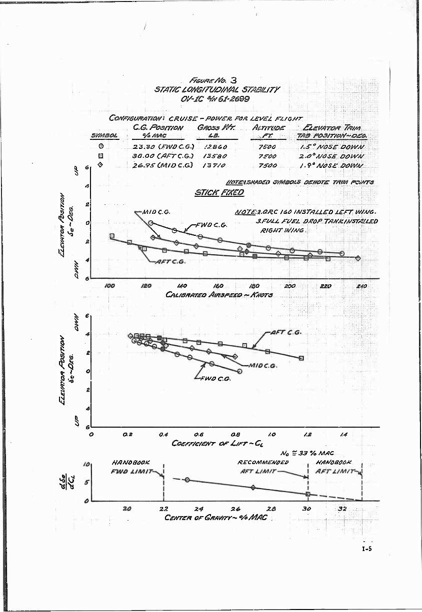
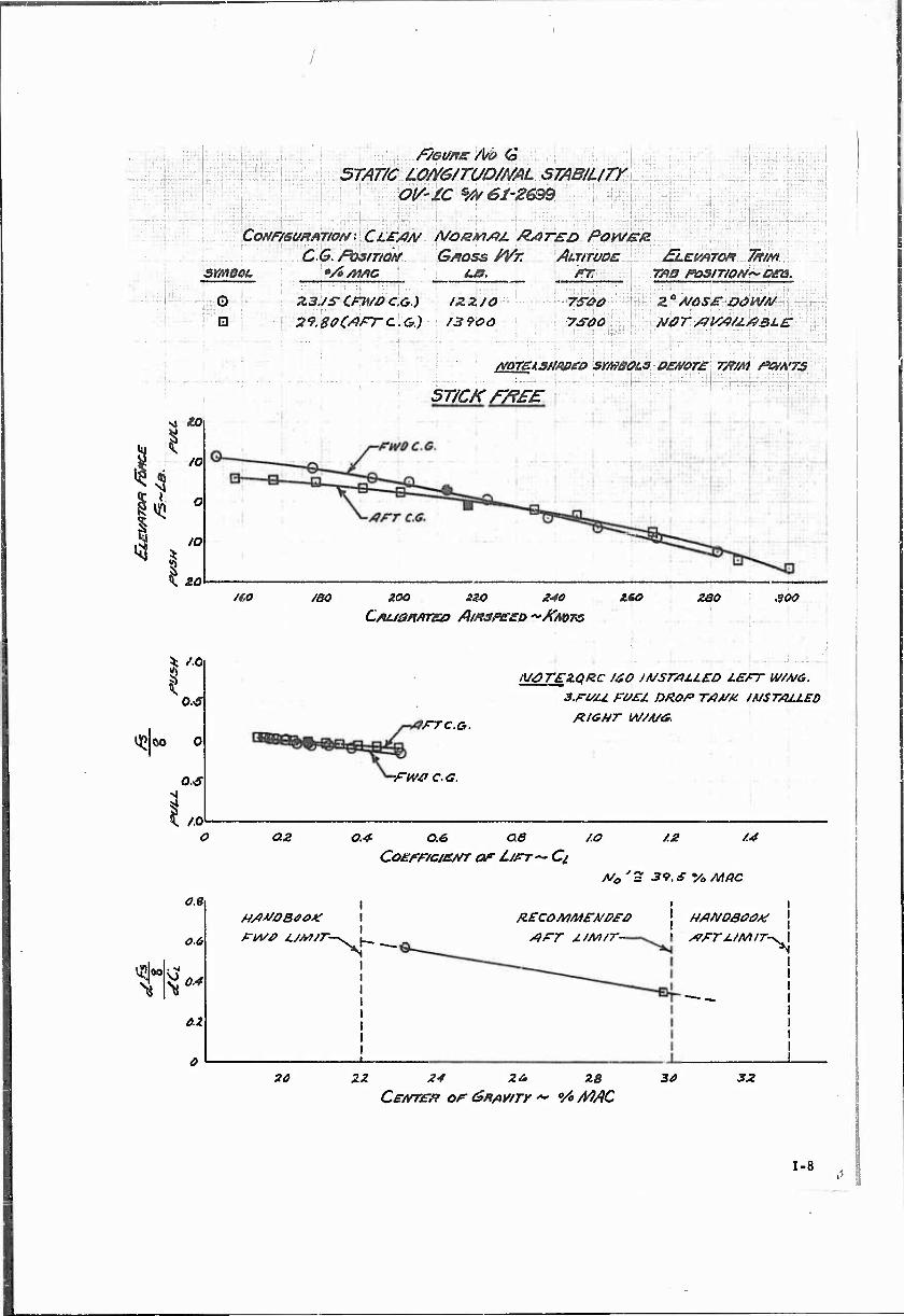
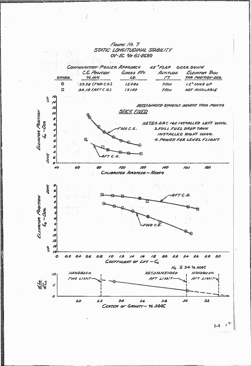
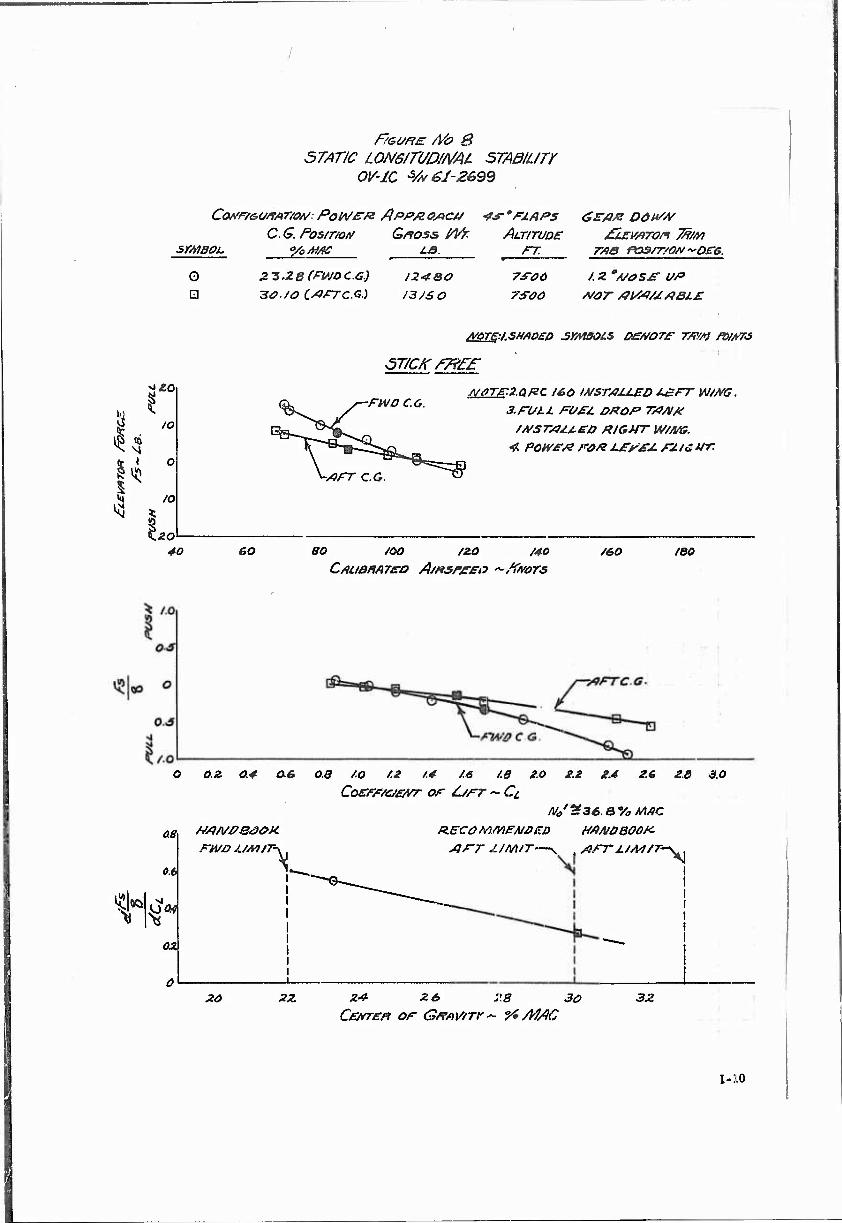
1.7.3 STATIC LONGITUDINAL STABILITY
The static longitudinal stability, both stick-fixed and stick- free, was evaluated at C.G. positions of approximately 23.3 percent MAC and 30 percent MAC for the takeoff, power-approach, cruise and maximum speed for level-flight trim conditions. All tests were conducted at an average density altitude of 7500 feet. The results of these tests are summarized in Figures No. 1 through 8, Section 3, Appendix I.
The OV-IC in the configuration tested and within the C.G. range recommended in this report (30 percent MAC) meets the requirement of MIL-F-8785 (ASG) that the stick-free (paragraph 3.3.1) and stick-fixed (paragraph 3.3.2) neutral points be aft of the most aft C.G. under all flight conditions. The neutral points obtained are summarized in Table 3.
8
TABLE 3. ST ICK-FREE AND STICK-FIXED NEUTRAL POINTS UNDER TESTED FLIGHT CONDITIONS
Trim Condition Stick-Fixed Neutral Point
N0 - percent MAC Stick-Free Neutral Point
No - percent MAC
PA
TO
CR
NRP
3h
38
33
32.5
36.8
M.5 |
k].5 \
39.5 !
The aft C.G. limit for the OV-IC as recommended in the Operators' and Crew Members' Manual is 33 percent MAC. The Naval Air Test Center Stability and Control Evaluation (Reference 1.1.g) recommended that the aft C.G, limit should be set at 30 percent MAC. The limited results of this evaluation indicate that the latter is a valid recommendation. As can be seen from the results in Table 3, stick-fixed neutral points for the cruise and maximum speed for level-flight trim points were forward of the Manual - recommended C.G. limit. On the basic of these tests and the limited testing accomplished, it is recommended that an aft C.G. limit, of 30 percent MAC be observed with the (iRC-l60-l installation. (Paragraph 1.9.1.b)
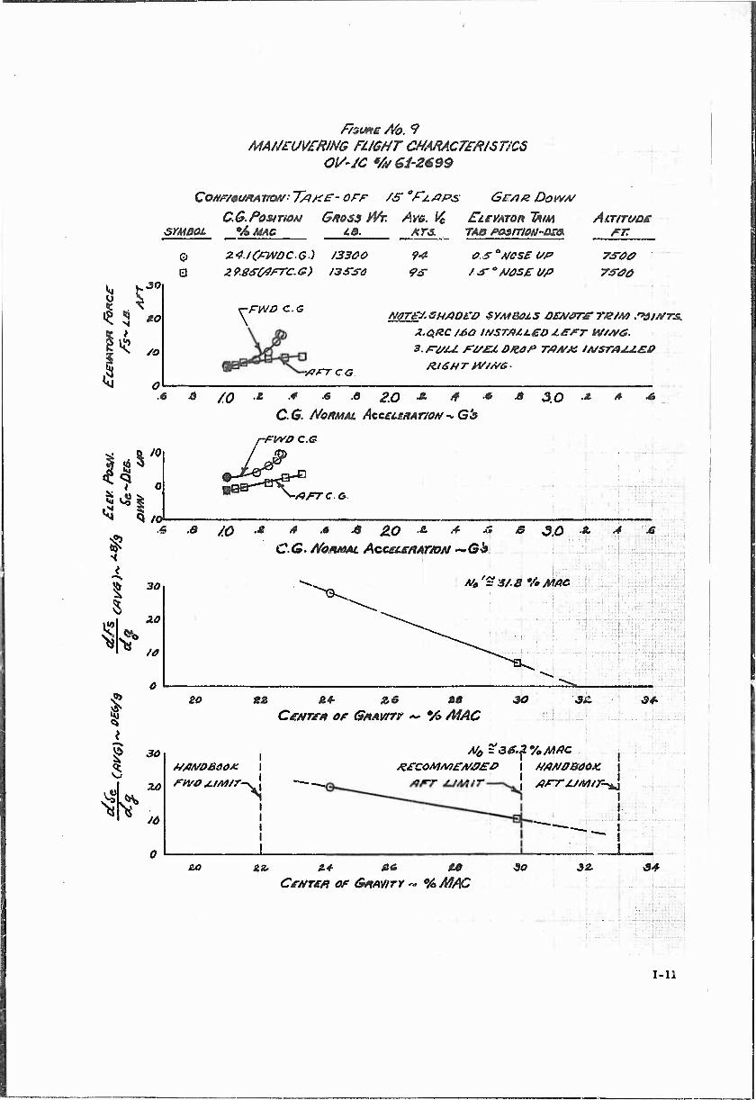
1.7.4 MANEUVERING STABILITY
Maneuvering stability tests were conducted at both a forward a,nd an aft C.G, using the steady-turn method. Tests were conducted in the cruise, takeoff and power-approach configurations. Turns were conducted at a constant airspeed while stabilizing at various load factors at varying altitudes. The results of these tests are presented in Figures No, 9 through 11, Section 3, Appendix I.
The stick-force and elevator-position gradients as a function of normal load factor were in all cases positive. All configurations tested were limited by aerodynamic stall. At forward C.G/s in the cruise configuration (I.e., forward of 26 percent MAC) as can be seen from Figure No. 10, the stick force per g was slightly higher than the maximum allowable specified in MIL-F-8785 (ASG), Paragraph 3.3.9.1. This was not considered objectionable. At an aft C.G, in the cruise configuration a condition occurred at the higher load factors that was
/
described by the pilot as "stick lightening.." This is substantiated by test results presented in Figure No, 10 which show the slope of the stick force versus g curve decreasing at the higheT g values. This decrease in gradient, however, was within the 50 percent of the average gradient allowed by MIL-F-8785 (ASG), Paragraph 3.3.9. This condition is acceptable at this C.G. but is indicative of the problems to be expected at more aft C.G.'s and previously reported in the Naval Air Test Center evaluation (Reference I.l.g),,
All maneuvering stability neutral points determined during this evaluation were aft of the most aft recommended C.G. (30 percent MAC) for operating with this system. Figure No. 9, however, shows a stick-free point neutral of 31.8 percent MAC, which is forward of the aft C.G. limit recommended by the Operators' and Crew Members' Manual Reference l.l.f). This reinforces the recommendation to limit the aft C.G. for OV-lC's to 30 percent MAC,
The results of this test indicated that the aft C.G. should be limited to 30 percent MAC when operating the OV-IC with the Q.RC-160-1 external store. (Paragraph 1.9.1.b)
].7.b DYNAMIC LONGITUDINAL STABILITY
Tests were conducted at both forward and aft CG.'s at a density altitude of 7500 feet to determine the characteristics of the dynamic longitudinal modes of motion of the 0V-1C with the QRC-lSO-l external store on the left wing and a full fuel drop tank on the right wing. The tests were conducted in the cruise,, takeoff and power-approach configurations.
In the following discussion the short-period mode is the periodic motion ov the airplane characterized by a change in angle of attack at an essentially constant airspeed. The period of this oscillation is a periodic motion of less than k seconds duration.
The short-period longitudinal mode of motion was investigated by abruptly displacing the longitudinal stick aft far enough from the trim condition to obtain an incremental acceleration of approximately 1/2 g. The control was then returned to the initial trim condition and the airplane response noted. The short-period response was essentially dead beat in all configurations tested.
The phugoid or long-period longitudinal mode was investigated by decreasing the airspeed from trim by approximately 10 knots, using the longitudinal control, and then returning the control to the trim position.
The phugoid oscillations in both the takeoff and power-approach configurations were lightly damped at the aft C.G. loading and
10
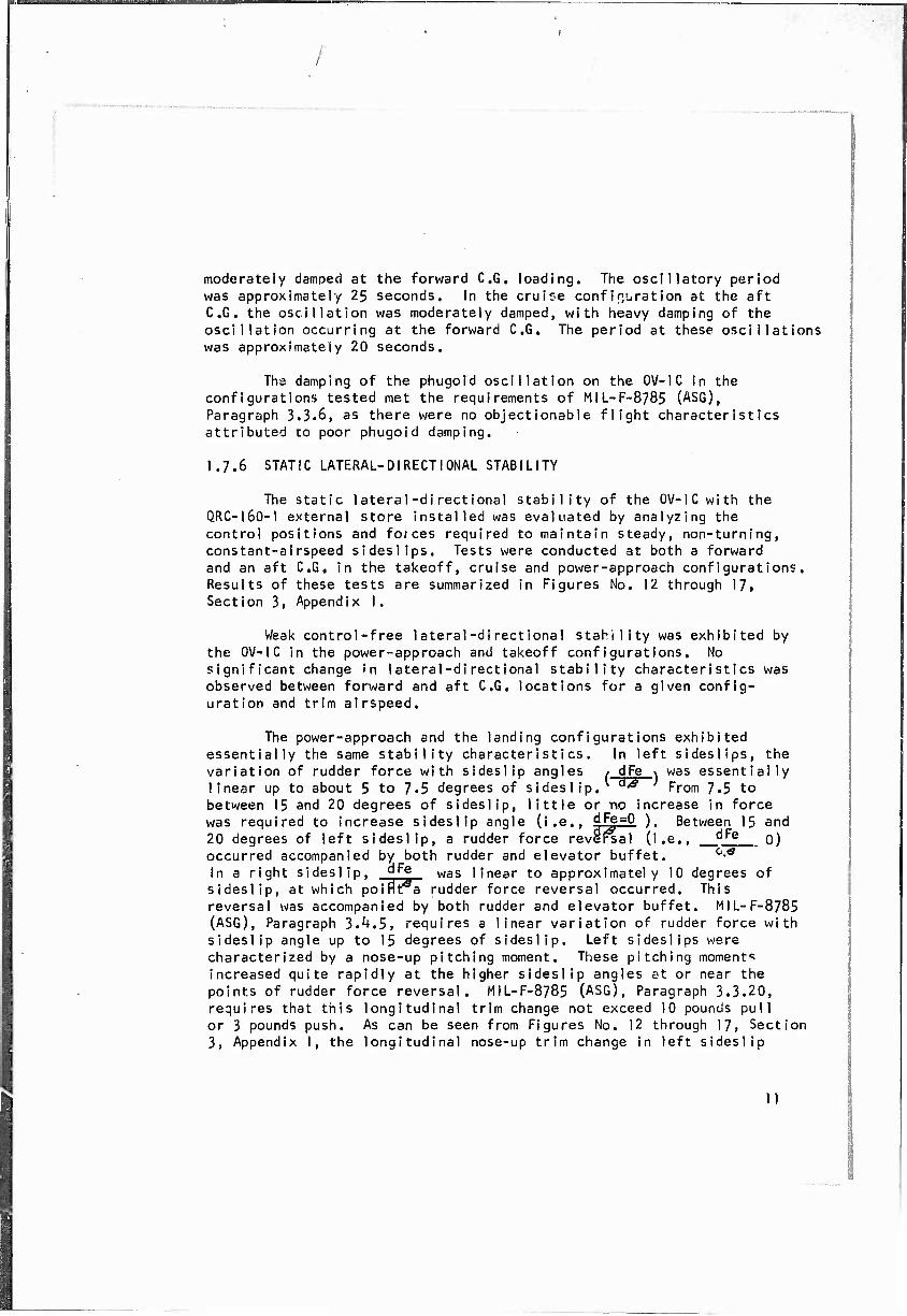
moderately damped at the forward C.G. loading. The oscillatory period was approximately 25 seconds. In the cruise confinuration at the aft C.G. the oscillation was moderately damped, with heavy damping of the oscillation occurring at the forward C.G. The period at these oscillations was approximately 20 seconds.
The damping of the phugoid oscillation on the 0V-1C in the configurations tested met the requirements of MIL-F-8785 (ASG), Paragraph 3.3.6, as there were no objectionable flight characteristics attributed to poor phugoid damping.
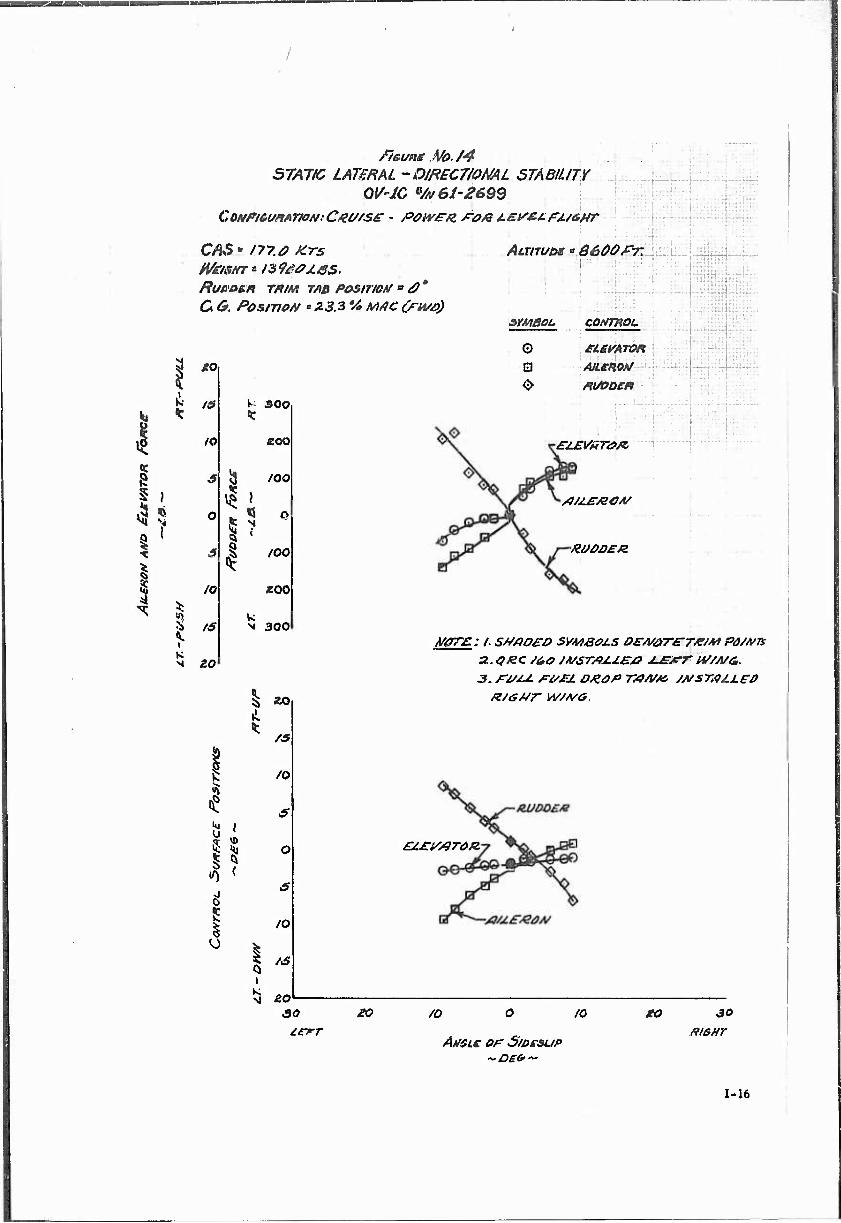
1.7.6 STATIC LATERAL-DIRECTIONAL STABILITY
The static lateral-directional stability of the OV-lCwith the O.RC-I6O-I external store installed was evaluated by analyzing the control positions and forces required to maintain steady, non-turning, constant-airspeed sideslips. Tests were conducted at both a forward and an aft C.G, in the takeoff, cruise and power-approach configurations. Results of these tests are summarized in Figures No. 12 through 17, Section 3, Appendix I.
Weak control-free lateral-directional stahility was exhibited by the 0V-1C in the power-approach and takeoff configurations. No significant change in lateral-directional stability characteristics was observed between forward and aft C.G. locations for a given config- uration and trim airspeed.
The power-approach and the landing configurations exhibited essentially the same stability characteristics. In left sideslips, the variation of rudder force with sideslip angles / dFe \ was essentially linear up to about 5 to 7.5 degrees of sideslip. °^ From 7.5 to between 15 and 20 degrees of sideslip, little or no increase in force was required to increase sideslip angle (i.e., dFe=0 ). Between 15 and 20 degrees of left sideslip, a rudder force revel^al (i.e., d^e o) occurred accompanied by both rudder and elevator buffet. ^ In a right sideslip, ^^ was linear to approximately 10 degrees of sideslip, at which poifrtTa rudder force reversal occurred. This reversal was accompanied by both rudder and elevator buffet. MIL-F-8785 (ASG), Paragraph 3.^.5, requires a linear variation of rudder force with sideslip angle up to 15 degrees of sideslip. Left sideslips were characterized by a nose-up pitching moment. These pitching momenta increased quite rapidly at the higher sideslip angles at or near the points of rudder force reversal. MIL-F-8785 (ASG), Paragraph 3.3.20, requires that this longitudinal trim change not exceed 10 pounds pull or 3 pounds push. As can be seen from Figures No. 12 through 17, Section 3, Appendix I, the longitudinal nose-up trim change in left sideslip
11
/
frequently exceeded the 3-pound specification requirement by as much as a factor of 3. Adequate dihedral effect as Indicated by the aileron force required to hold a steady sideslip ( !ja-) was present in a left
sideslip, and near neutral dihedral effect ( "§'^"" = 0) was present in
a right sideslip, MJL-F-8785 (ASG), Paragraph 3.^.7, requires a positive dihedral effect. In the cruise configuration no objectionable control- free stability characteristics were apparent until pedal forces of over 200 pounds, which Is higher than the MIL-F-8785 (ASG) requirement, were applied. At these higher pedal forces, there was a tendency for a force reversal. The dihedral effect remained positive and the longitudinal trim change was negligible at this configuration.
The control-fixed static lateral-directional stability was satisfactory in all configurations tested. Both the elevator and aileron positions as a function of sideslip were positive with no reversing tendencies. In right sideslips in all configurations tested there was a tendency for the control-fixed dihedral effect (i.e., cf\a
to decrease, but it never approached zero. The rudder position versus sideslip was essentially linear to the limit sideslip angles in all configurations tested.
On the basis of these tests, it Is recommended that notes concerning the problem areas mentioned be incorporated in the Operators' Manual for the OV-lCwhen the (iRC-J60-l is Installed. (Paragraph 1,9.l,c) It is also recommended that further tests be conducted on standard OV-l's to determine if the same problems exist. If present In all configurations, appropriate notations should be made in the Operators' and Crew Members' Manual. (Paragraph 1.9.2)
1.7.7 DYNAMIC LATERAL-DIRECTIONAL STABILITY
The dynamic lateral-directional stability mode of mot'on was evaluated by noting the airplane's response to a release from a steady non-turning sideslip. Releases were accomplished by both rapidly neutralizing the pedals and by releasing the pedals. Tests were accom- plished at both a forward CG. (23 percent MAC) and an uft CG. (29.5 percent MAC) in the power-approach, takeoff and cruise configurations.
The lateral-directional mode (i.e., Dutch Roll) was heavily damped In all configurations tested. All releases ended up In a slowly divergent spiral. No objectionable flight characteristics were attributed to the lateral-directional mode of motion.
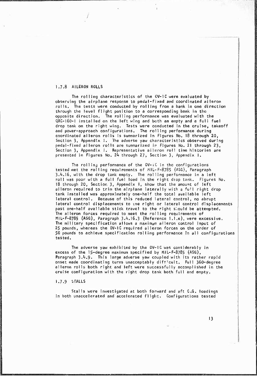
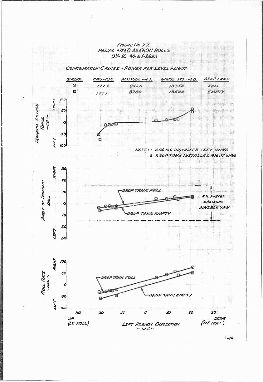
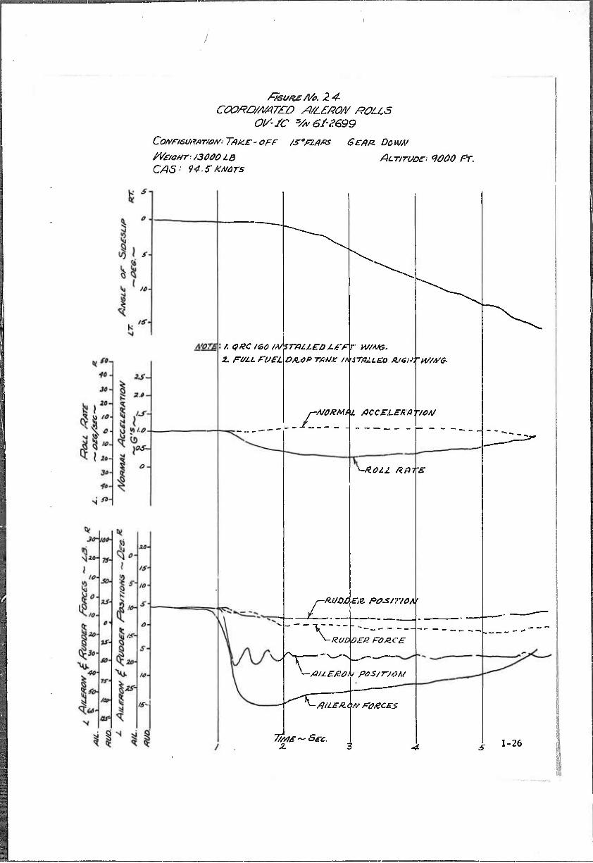
1.7.8 AILERON ROLLS
The rolling characteristics of the OV-lCwere evaluated by observing the airplane response to pedal-fixed and coordinated aileron rolls. The tests were conducted by rolling from a bank in one direction through the level flight position to a corresponding bank in the opposite direction. The rolling performance was evaluated with the QRC-I60-I installed on the left wing and both an empty and a full fuel drop tank on the right wing. Tests were conducted in the cruise, takeoff and power-approach configurations. The rolling performance during coordinated aileron rolls is summarized in Figures Mo. 18 through 20, Section 3, Appendix I. The adverse yaw civjracteristics observed during pedal-fixed aileron rolls are summarized ir Figures No. 21 through 23, Section 3, Appendix I. Representative aileron roll time histories are presented in Figures No. 2k through 27, Section 3, Appendix I.
The rollinj performance of the OV-1C in the configurations tested met the rolling requirements of MlL-F-8785 (ASG), Paragraph 3.^.16, with the drop tank empty. The rolling performance In a left roll was poor with a full fuel load in the right drop tank. Figures No. 18 through 20, Section 3, Appendix I, show that the amount of left aileron required to trim the airplane laterally with a full right drop tank installed was approximately one-half the total available left lateral control. Because of this reduced lateral control, no abrupt lateral control displacements to me right or lateral control displacements past one-half available stick travel to the right should be attempted. The aileron forces required to meet the rolling requirements of MIL-F-8785 (ASG), Paragraph 3.^.16.3 (Reference 1.1.e), were excessive. The military specification allows a maximum aileron control input of 25 pounds, whereas the 0V-1C required aileron forces on the order of 50 pounds to achieve specification rolling performance In all configurations tested.
The adverse yaw exhibited by the OV-1C was considerably in excess of the 15-degree maximum specified by MIL-F-8785 (ASG), Paragraph 3.^.9. This large adverse yaw coupled with its rather rapid onset made coordinating turns unacceptably dift'cult. Full 360-degree aileron rolls both right and left were successfully accomplished in the cruise configuration with the right drop tank both full and empty.
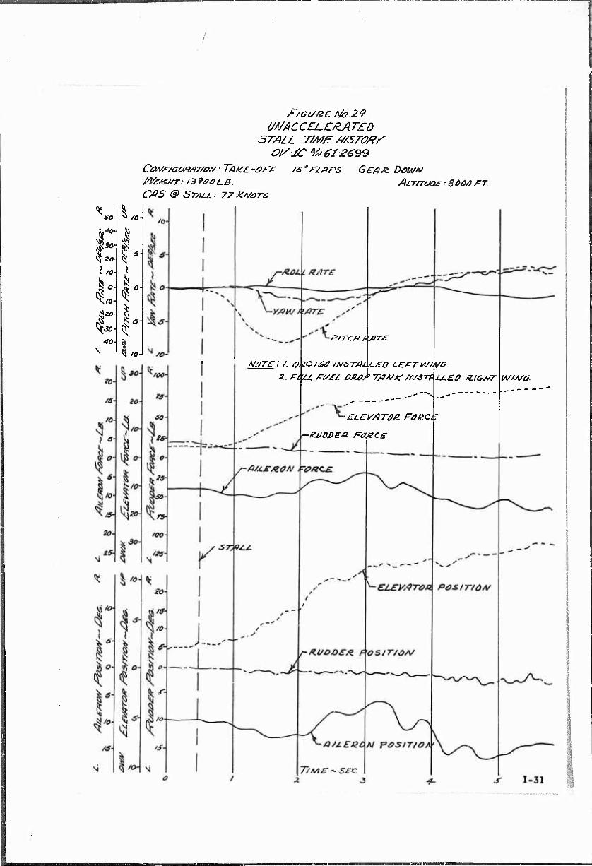
1.7.9 i-TALLS
Stalls were investigated at both forward and aft CG, loadings in both unaccelerated and accelerated flight. Configurations tested
13
üfffr^ni—'p^awMg *mM
included cruise, takeoff and power-approach. The stalling performance on the OV-lCwith the Q.RC-160-1 installed is summarized in Figure No. 28, Section 3, Appendix I. The calibrated airspeed at stall for several gross weights is shown in Table k.
TABLE 4, CALIBRATED AIRSPEED IN STALL TESTS
—
Configuration
Calibrated Ai rspeed at Stall - Knots
11,000 lb 13,000 lb 15,000 lb
PA 64 69.5 74
1 TO 67.5 74 79
CR 77 84 90
There was little difference in the stalling characteristics of the 0V-1C at the forward and aft C .G. loadings.
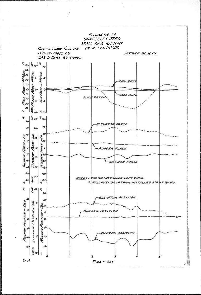
Stalls in the cruise configuration were characterized by a very noticeable buffet that occurred approximately 10 knots above the stall. Unaccelerated stalls in this configuration broke cleanly with no tendency to drop a wing. A time history of an unaccelerated stall in the cruise configuration is shown in Figure No. 30, Section 3. Appendix I. Accelerated stalls did not tend to break clean but were characterized by a break, partial recovery, then another break. The airplane, during these stalls, tended to roll out of the turn.
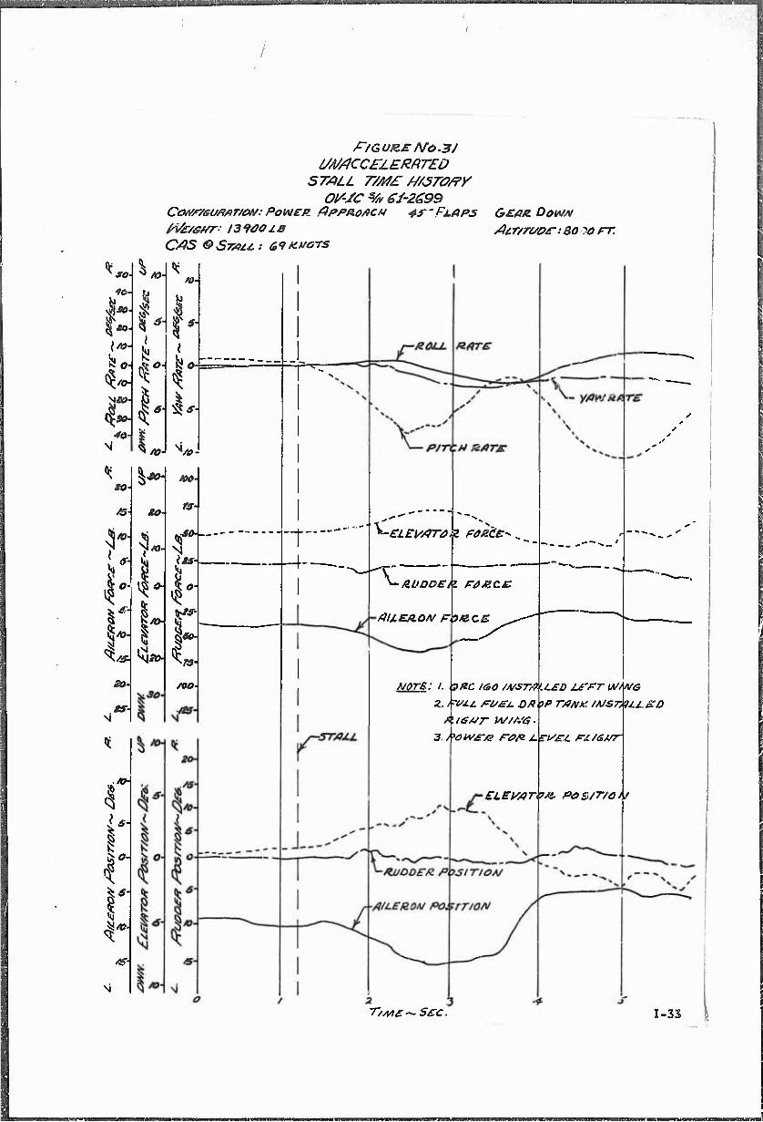
Stalls in the takeoff and power-approach configurations were characterized by a clean breaking stall with no stall warning. Time histories of an accelerated and an unaccelerated stall in the power- approach configuration are depicted in Figures No, 31 and 32, Section 3, Appendix I. Stalls with inadequate warning are especially dangerous on airplanes that must be operated near the stall to achieve ST0L performance. In the takeoff and power-approach configurations the 0V-1C did not meet the stall warning requirements of MIL-F-8785 (ASG), Paragraph 3.6.3. MIL-F-8785 (ASG) requires aircraft to have adequate stall warning. On the basis of the;e tests, it is recommended that an adequate stall warning device be incorporated on all 0V-1C series airplanes. (Paragraph 1.9.4) It is further recommended that tests be conducted to determine the feasibility of using an angle-of-attack indicator on the 0V-1C. (Paragraph 1.9.5)
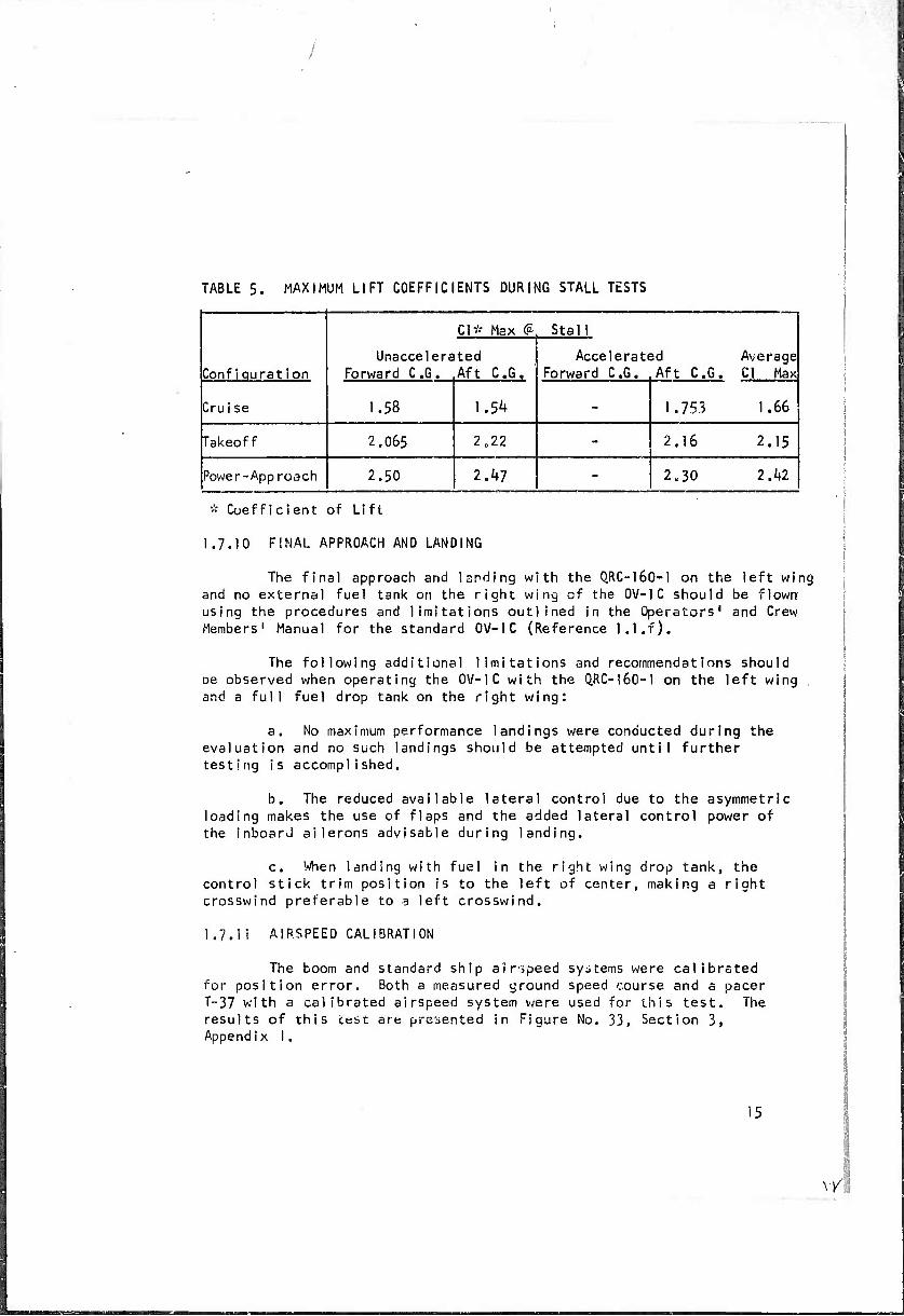
Table 5 summarizes the maximum lift coefficients obtained during the stall investigations:
14
TABLE 5. MAXIMUM LIFT COEFFICIENTS DURING STALL TESTS
Confiquratlon Unaccelers
Forward CG.
Cl* Max (£. Stall
3d Aft CG.
Average Cl Max
ted Aft CG.
Acceleratf Forward CG.
Crui se 1.58 1.54 - 1.753 1.66
Takeoff 2.065 2.22 - 2,16 2.15
Power-Approach 2.50 2.47 - 2U30 IM
* Coefficient of Lift
1.7.10 FINAL APPROACH AND LANDING
The final approach and landing with the Q.RC-160-1 on the left wing and no external fuel tank on the right wing of the OV-IC should be flown using the procedures and limitations outlined in the Operators' and Crew Members' Manual for the standard OV-IC (Reference l.l.f).
The following additional limitations and recommendations should be observed when operating the OV-IC with the Q.RC-16O-I on the left wing , and a full fuel drop tank on the right wing:
a. No maximum performance landings were conducted during the evaluation and no such landings should be attempted until further testing is accomplished.
b. The reduced available lateral control due to the asymmetric loading makes the use of flaps and the added lateral control power of the inboard ailerons advisable during landing.
c. When landing with fuel in the right wing drop tank, the control stick trim position is to the left of center, making a right crosswind preferable to a left crosswind.
1.7.11 AIRSPEED CALIBRATION
The boom and standard ship airspeed systems were calibrated for position error. Both a measured ground speed course and a pacer T-37 with a calibrated airspeed system were used for this test. The results of this test are presented in Figure No. 33, Section 3, Appendix I.
\Y\
The position error of the standard system is within the limits of MIL-1-6115A (Reference l.l.h) in all cases except in the high-speed flaps-down cases in the power-approach and takeoff configurations in which the limit exceeded by approximately 1 knot.
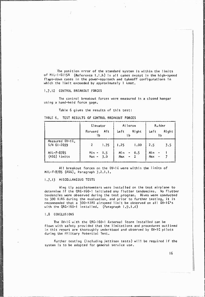
1.7.12 CONTROL BREAKOUT FORCES
The control breakout forces were measured in a closed hangar using a hand-held force gage.
MIL-F-8785 Min - 0.5 Min - 0.5 Min - I (ASG) Limits Max - 3.0 Max - 2 Max •- 7
All breakout forces on the GV-IC were within the limits of MiL-F-8785 (ASG), Paragraph 3.2.1.1.
1.7.13 MISCELLANEOUS TESTS
Wing tip accelerometers were installed on the test airplane to determine If the Q.RC-160-1 initiated any flutter tendencies. No flutter tendencies were observed during the test program. Dives were conducted to 300 KIAS during the evaluation, and prior to further testing, it is recommended that a 300-KIAS airspeed limit be observed on all OV-lC's with the QRC-I60-I installed. (Paragraph l.g.l.d)
1.8 CONCLUSIONS
The OV-IC with the QRC-160-1 External Store installed can be flown with safety provided that the limitations and procedures outlined in this report are thoroughly understood and observed by OV-IC pilots during the Military Potential Test.
Further testing (including jettison tests) will be required if the system is to be adopted for general service use.
16
The Operators' and Crew Members' Manual (Reference I.l.f) should be updated to Include single-engine performance and minimum control speeds at altitudes above sea level.
Additional testing should be conducted to determine whether the lateral-directional problems uncovered during this program are an inherent characteristic of 0V-1C aircraft.
The OV-IC has inadequate stall warning in the takeoff and power-approach configurations.
1,9 RECOMMENDATIONS
1.9.1 If the (1RC-160-1 installation on the OV-IC is adopted for service use, jettison tests as well as tests to expand the flight envelope should be conducted. Until this is accomplished, no QRC-I60-I external store jettisons should be attempted and the following flight limitations and configurations, specified in this report, should be observed:
a. No STOL takeoffs should be attempted with the Q,RC-l60-l installed until further tests are conducted (Paragraph 1.7.2, Page 6 ).
b. An aft C.G. limit of 30 percent MAC should be observed with the CIRC-I60-I installed (Paragraph 1.7.3, Page 9 ).
c. Pilots flying the OV-IC with the QRC-160-1 installed should be aware of the lateral-directional stability and control problems mentioned in the report (Paragraph 1.7.6, Page 12 ).
d. Prior to further tests an airspeed limit of 300 KIAS should be observed on OV-IC airplanes with the QRC-lSO-l installed (Paragraph 1.7.13, Page 16 ).
1.9.2 Further tests should be conducted to determine if the lateral- directiona1 problems observed during this test are characteristic of standard OV-lC's. If they are characteristic, appropriate notation should be inserted in the Operators' Manual (Paragraph I.7.61 Page |2 ).
1.9.3 The OV-IC Operators' Manual should be updated to include single- engine performance and minimum control speeds at altitudes above sea level (Paragraph 1.7.2, Page 8 ).
1.9.^ An adequate stall warning system should be incorporated on all 0V-1C airplanes (Paragraph 1.7.9, Page l^ ).
17
^—li-JLL—_*-
1.9.5 An angle-of-attack indicator should be evaluated on OV-1 series
airplanes (Paragraph 1.7.9, P«ge I'+K
18
■ s:-:v ■.::i.„.
SECTION 2 -- DETAILS AND RESULTS OF TESTS
The information and details of test normally presented in this section are incorporated in Section 1.7, Findings.
Ol/SC V* 61-2C99 Cow/eo/t/DT/ofif: POWER &ppRo/icu *?'FLAPS QEAAOOMN
Ws/s//r i39aoJ.B dcr/rc/os-:ao 10rr.
^ so 46- I. I
ß o- ^ o
40-
m-
I
ro* ^z*»-
so
/s
S"*H ice
SO-
i: ac-
ts-
^
1
its-
I- /oo-
•f v>
auDDEH Fajzcc
AllEAOM P.9&CE
£iEi//7raz Fames'* > __
A/OrE: I. ,?ÄC /<Sö /A/'STtfi.LED JJFFT \A//MG
z. FMCZ. risej. DP\>P rxvvAf wsTyßtjLSß
ZLEWTii/t PaS/TfOiS
T//ui£~- SEC. 1-33
F/GUJZC A/0.3JL
#CC£L£/ZAT£D STAU T/M£ M/5TO/?y
OI/-/C $& 6J-2699 Ccw/<s<MMT/tw: POWER/tpp/zoACti ^J-TXAPS Ge/ifii. Down
CAS 9 ör/U.t: 94.S-ACA/aTS /?7- /. <ä a s
$*>■
Is,*.
si
to
I so
10-
I " /o
L \
6-
r
/o-
\
Z5
\'3o\ *<IOO-
to-
I L ^
A:
fs/o-
T3-
N
/iJo-
/s-
\ /o-
\
I.
/o
20-
/S-
/o-
5-
x
-d.
i
P/TCrt RATS
RO/U-U/tTE
v/fh/jefire
r £r/i£-Mqross / -c;>ecr
-/zi/oorx yo/ics
— /}/£ E/ZOA/ ro&cE
3. EUJU. WZL OR
3. Pi7Ul/£-/e ra/s jLefS/.
ElEls/irOR POS
TAJLLEO ET (A/'A/G
jPTJJA/M. VA/srPjULEO RJÜA}
E'A/GA"'
A.
--An. 'SX^y-
-STAJ./.
IT/OA/
-t
ROOD^/S. POSIT/aw
: : , ■■•> os)Tto*A
T/ME ~ SB ?
„ s .'\*.
1-34
(*1
0 s!
Q ^
S O <1 □
5^
Q s?
o
Q ^0
§
§
§ s §
I
.....-. , i
I
W3J.S.-AS WOOff
V) «5» «i ?
S-MO/VTV ~ -ZfOV&J A/O/J^/SOc/
1-35
APPENDIX I I GENERAL AIRCRAFT INFORMATION
Flight Limitations. Weight and Balance and Instrumentation
1.0 FLIGHT LIMITATIONS
The flight and operating limits enumerated in the Operators' and Crew Members' Manual (Reference l.l.f) were observed during this evaluation of the QRC-16C-1 installed on the OV-IC.
The following limits observed during the program are of particular interest:
a. Gear and Flap Limits
(1 ) Maximum airspeed with gear and flaps extended is 150 KIAS. (2) Maximum normal acceleration with gear and flaps extended
is 2.0 g 's.
b. Prohibited Maneuvers
(1 ) Intent ional sp i ns . (2) Rolling pull-outs in turbulent air. (3) Abrupt control reversals.
c. Airspeed Limitations
Maximum permissible airspeed with external stores is 300 knots calibrated airspeed (KCAS).
d. Normal Acceleration Limits
(1) The maximum positive normal acceleration at 14,000 pounds gross weight is k,} g's.
(2) The maximum negative normal acceleration at 14,000 pounds gross is -].k g's.
(3) Maximum permissible negative load factor varies linearly from -1.1 g's at 280 KIAS to 0 g's at maximum airspeed.
2.0 WEIGHT AND BALANCE
The test airplane was weighed and balanced in a closed hangar with empty fuel, full oil and test instrumentation installed. The results of this weight and balance were:
ll-l
Basic Weight + Oil Centei of Gravity (C.G.)
10,450 lb 30,25 % MAC
The following gear-down, engine-start loading conditions were used during this evaluation. All data flights (less ballast) wet loaded as f o 1 1 Otis :
Item Weight - lb Arm - in.
Basic Weight + 01 1 10,450 164.43
2 Crew 350 61.00
Full Main Tank Fuel (297 Gal)* 1,930 161.00
QRC-160 Left Wing 196 170.00
Right Wing Drop Tank 137 162.50
Full Fuel Drop Tank (150 gal)* 975 162.50
*Fuel weight computed 6.5 lb/gal
This loading resulted in a mid C.G, loading of
Gross Weight Center of Gravity
14,038 lb 27.3 % MAC
The aft C.G, was obtained by using the above loadings and adding 250 pounds of ballast in the aft cargo compartment (Station 318). This resulted in a takeoff loading condition as follows:
Gross Weight Center )f Gravity
14,288 lb 29.4 % MAC
The forward C,G, was obtained by using the basic loading and adding 34l pounds of ballast in the nose at Station 11.5. This resulted in the following takeoff loading condition:
ütüaS wetgnt
Center of Gravity 14,379 lb 23.3 % MAC
11-2
The asymmetric lateral moment obtained by loading the (iRC-160-1 on the left wing fuel tank rack and a full load of luel in the right wing drop tank was 169,^60 in. - lb of right rolling moment. The asymmetric lateral moment obtained by loading the Q.RC-160-1 on the left wing fuel tank rack with no external stores on the right wing was 36,260 in. - lb of left rolling moment.
3.0 INSTRUMENTATION
3.1 The following flight test instrumentation was installed and maintained in CV-IC, S/N 61-2699, by personnel of the Logistic« Division of the USAATA, Edwards AFB, California.
Recorded on a 50-channel oscillograph were:
i, Angle of Attack 2. Angle of Si des 1 ip 3. Roil Rdte k. Yaw Rate 5. Pitch Rate 6. Longitudinal Stick Force
Lateral Stick Force 8. Pedal Force 9. Elevator Position 10. Rudder Position 11. Left-Hand Aileron Position 12. Flap Position 13. Center-of-Gravity Normal Accelerometer \k. Speed Brake Position 15. Pilot's and Observers' Event 16. Left and Right Power Lever Position 17- Gear Extension Signal 18. Lef Wing Tip Leading Edge Accelerometer 19. Lef Wing Tip Elastic Axis Accelerometer 20. Right Wing Tip Elastic Axis Accelerometer
3.2 The following sensitive, -alibrated instruments were installed in the cockpit and hand-recorded by an engineering observer:
a. Boom Ai rspeed b. Boom Alt imeter c. Standard System Airspeed d. Standard System Altimeter e. Free Air Temperature f. Engine Torque Pressure (Both Engines) g. Exhaust Gas Temperature (Both Engines)
11-3
Engine Nj Speed (Both Eng Ines) Engine Inlet Temperatures (Both Engines) Vertical Accelerometers Oscillograph Counter Angle of Sides]ip Rudder Pedal Force
Weight control was maintained by calibrating the standard ship fuel quantity indicator.
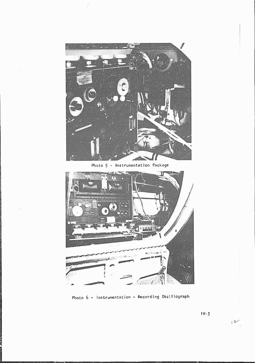
Photographs No. k, 5 and 6, Appendix IV, show details of the instrumentation installation.
\\~k
Symbol
KIAS KTAS KCAS or CG. MAC
\
//.
Fe Fa Fr
£ PA TO CR NRP
CAS
APPENDIX I II SYMBOLS AND ABBREVIATIONS
Def ini t ion
Knots Indicated Airspeed Knots True Airspeed Knots Calibrated Airspeed Center of Gravi ty Mean Aerodynamic Chord Stick Fixed Neutral Point Stick Free Neutral Point Lift Coefficient Elevator Deflection Ai leron Deflect ion Rudder Deflection Elevator Force Ai leron Force Rudder Force Dynamic Pressure Si desli p Angle Power Approach Takeoff Cruise Normal Rated Power
Units
Kts Kts Kts % MAC Jn % MAC % HAG
Ib/sq ft, deg
MM
APPENDIX IV PHOTOGRAPHS
IV-I
Photo k - Instrumentation - Engineer's and Pilot's Panel
AD Accession No. Final Report of USATECOM Project No, 6-3-6711-03, Airworthiness Certification Test of the QRC-16Ü-1 Installed on the OV-1C Airplane, January I965, DA Project No. l-G-6-'+1212-05^+0 (70 pp, 6 tables, 6 photographs, 33 figures) US Army Aviation Test Autivity (USAATA) Unclassified Report
The ORC-160-1 is an ECM External Store weighing 195 pounds used for the protection of aircraft. For this test, the inata1lation was mounted at the drop tank station on the left wing of tha 0V-1C. The nRC-i60-l can be employed with safety when mounted on the left wing of the OV-IC with either a full or an empty 150-gallon drop tank mounted on the right wing provided that a restricted flight envelope is observed. The results of this evaluation concurred with the recommendation by the Naval Air Test Center of an airplane centcr-of-gravity (C.G.) limit of 30 percent mean aerodynamic chord (MAC) rather than the Operators' Manual limit of 33 percent MAC. Additional testing should be conducted to determine whether the lateral- directional problems uncovered during this program are inherent characteristics of OV-1C aircraft. The Operators' Manuel for the OV-1C should be updated to include single-engine performance and minimum control speeds at altitudes above sea 1 eve 1.
AD Accession (._. Final Report of ÜSÄTEC0M Project No. 6-3-6711-03, Airworthiness Certification Test of the Q.RC-160-1 Installed on the OV-1C Airplane, January 1965. DA Project No. I-G-6-41212-D540 (70 pp, 6 tables, 6 photographs, 33 figures) 'JS Army Aviation Test Activity (USAATA) Unclassified Report
The O.RC-I6O-I is an ECM External Store weighimj 195 pounds used for the protection of aircraft. For this test, the installation was mounted at the drop tank station on the left wing of the 0V-1C. The QRC-I60-I can be employed with safety when mounted on the left wing of the OV-1C with either a full or an empty 150-gallon drop tank mounted on the right wing provided that a restricted flight envelope is observed. The results of this evaluation concurred with the recommendation by the Naval Air Test Center of an airplane center-of-gravity (C.G,) limit of 30 percent mean aerodynamic chord (MAC) rather than the Operators' Manual limit of 33 percent MAC. Additional testing should be conducted to determine whether the lateral- directional problems uncovered during this program are inherent characteristics of OV-1C aircraft. The Operators' Manual for the OV-1C should be updated to include single-engine performance and minimum control speeds at altitudes obuve sea level .