ASME Journal of Mechanical Design Minor and Mukherjee 1 Under-Actuated Kinematic Structures For Miniature Climbing Robots Mark A. Minor Assistant Professor Department of Mechanical Engineering University of Utah Salt Lake City, UT 84112 Ranjan Mukherjee Associate Professor Department of Mechanical Engineering Michigan State University East Lansing, MI 48824 Submitted: August 2001 Accepted with minor revisions May 31, 2002 Resubmitted with minor revisions September 19, 2002 Abstract This paper presents two biped designs for miniature climbing robots. The designs use under- actuation to satisfy space and weight constraints. In the first design, one actuator provides steering and another two propel the robot in a cartwheel style gait. The cartwheel gait is quite effective but space required for the maneuver precludes certain applications. The limitation is overcome in the second design, which uses under-actuation to provide two different forms of locomotion. It uses a crawling stride in confined environments and a faster pivoting gait in open environments. Such adaptability is achieved without increasing the number of actuators. Both robots have been built and have successfully demonstrated their mobility and maneuverability.
Transcript
ASME Journal of Mechanical Design
Minor and Mukherjee 1
Under-Actuated Kinematic Structures For Miniature Climbing Robots
Mark A. Minor
Assistant Professor Department of Mechanical Engineering
University of Utah Salt Lake City, UT 84112
Ranjan Mukherjee Associate Professor
Department of Mechanical Engineering Michigan State University East Lansing, MI 48824
Submitted: August 2001 Accepted with minor revisions May 31, 2002
Resubmitted with minor revisions September 19, 2002
Abstract
This paper presents two biped designs for miniature climbing robots. The designs use under-actuation to satisfy space and weight constraints. In the first design, one actuator provides steering and another two propel the robot in a cartwheel style gait. The cartwheel gait is quite effective but space required for the maneuver precludes certain applications. The limitation is overcome in the second design, which uses under-actuation to provide two different forms of locomotion. It uses a crawling stride in confined environments and a faster pivoting gait in open environments. Such adaptability is achieved without increasing the number of actuators. Both robots have been built and have successfully demonstrated their mobility and maneuverability.
ASME Journal of Mechanical Design
Minor and Mukherjee 2
1. Introduction Miniature climbing robots deployed in urban environments for reconnaissance can reduce risks to security personnel. Such robots should be sufficiently small to avoid detection and capable of travel on exterior and interior surfaces of a building. There are few gripping techniques suitable for adhering to flat inclined surfaces, and suction, despite limitations, is the inevitable choice for most practical applications. The purpose of our research has been to design miniature climbing robots, based on suction gripping, with high mobility characteristics. These characteristics include ability to scale surfaces with arbitrary inclination, complete mobility of travel on these surfaces, ability to travel with a reasonable pace, and transition between surfaces of different inclination. Although the ability to transition between surfaces of different inclination and complete mobility on the surfaces requires multiple actuators, the weight of the actuators and dynamic loads resulting from fast pace of travel can surpass limits of commercially available miniature suction mechanisms. The design challenge is therefore to provide full range of mobility using the fewest actuators.
The need for using fewer actuators in miniature climbing robots can be further appreciated if operational requirements are taken into consideration. Effective operation requires that the robots be small in size and semi-autonomous. They should therefore be untethered and capable of carrying sensors, computational resources, communication devices, power supply, and suction pumps. All of this hardware will occupy significant space and constrain the volume and location of space available for actuator placement. The weight of the hardware will also be significant and limit the number of actuators that can be incorporated.
The approximate dimensions of our robots were determined from functionality requirements and cost considerations. While functionality dictated that the robots have small dimensions to avoid detection, cost considerations suggested fabrication using off-the-shelf components and imposed limitations on miniaturization. Such limitations, for example, due to lack of availability of suction mechanisms in very small sizes, and high cost of custom-made lightweight high-density rechargeable batteries, lower bounded the physical size of specific components. Subject to these bounds, we designed our robots to have the smallest size with complete functionality. Among multiple kinematic structures that offered to provide complete functionality, we chose the biped morphology to minimize the size of our robots. In comparison to climbing robots discussed in the literature, our two designs presented here occupy significantly lower volume; of the order of 500 cc and 750 cc, respectively.
The traditional approach to robot design suggests that kinematic structures have at least as many degrees-of-freedom (DOF) as the dimension of the configuration space. To this end, robots are designed with number of joints equal to or exceeding the dimension of the configuration space with each joint driven by a single actuator. The configuration space of a biped that can transition between two flat surfaces of arbitrary inclination is five-dimensional. Three coordinates describe the location on the flat surface where the foot will be placed; the other two coordinates define the normal to the surface for proper foot orientation. A traditional design of our robot, based on five actuators, would be heavy and its weight would exceed the limits of the suction mechanism. Furthermore, the space used by five actuators will leave little space for placement of other hardware. This led us to explore under-actuated designs that incorporate fewer actuators but do not sacrifice mobility or other functionality. Such designs reduce the weight of the robot for two good reasons. First, the weight of each actuator constitutes a substantial portion of the total
ASME Journal of Mechanical Design
Minor and Mukherjee 3
weight, and second, elimination of an actuator allows us to downsize the others since each actuator is typically designed to carry the weight of the others.
In this paper we present two under-actuated kinematic designs for miniature climbing robots. We survey the literature on climbing robots and applications of under-actuation in section 2. Earlier work on under-actuation has relied mainly on the use of passive joints, where actuators are absent. Our concept of under-actuation is different and we use a single actuator to drive multiple joints simultaneously, and/or discretely, with none of the joints being passive. Our first design is presented in section 3. It utilizes three actuators in an under-actuated configuration with four joints; two of them are simultaneously driven by one of the three actuators. The robot achieves good mobility with a cartwheel style gait and steering capability on one foot. Our second design is presented in section 4. It uses three actuators to drive one prismatic joint and four revolute joints. One actuator drives the prismatic joint and two revolute joints in three discrete modes. In the first mode, the power from the actuator is transferred entirely to the prismatic joint to generate a crawling stride. In the second and third discrete modes the power is simultaneously transferred to the prismatic joint and either of the two revolute joints. The robot alternates between the second and third discrete modes to generate a pivoting gait suitable for open environments. Both robots were fabricated and used to demonstrate their feasibility and full range of mobility. In section 5 we provide future research directions and concluding remarks.
2. Background The concept of under-actuation in mechanical systems is based on the simple idea of minimizing the number of actuators without sacrificing basic functionality. Although a reduction in the number of actuators imposes constraints and complicates motion planning and control tasks, it is justified in many applications by the reduction in cost, weight, volume, and power consumption. Despite these advantages, the goal of under-actuation cannot be pursued in isolation since the design of under-actuated systems is closely linked to advances in motion planning and control.
In the literature, an under-actuated system is defined as one that has greater number of degrees-of-freedom (DOF) than the number of actuators [1, 2]. From a Lagrangian mechanics point of view, such systems have fewer non-conservative generalized forces than the number of generalized coordinates [3]. A few examples of such systems are articulated multibody systems floating freely in space, marine vehicles, and robot manipulators with passive joints. Free-floating systems in space refrain from using thrusters to conserve on-board fuel. In this under-actuated mode of operation, where generalized forces are absent, the configuration control problem is complicated by nonholonomic constraints resulting from conservation of angular momentum [4, 5]. Although these nonholonomic constraints result from integrability of dynamic equations, nonholonomic systems, in general, are often regarded as under-actuated systems. For systems with kinematic nonholonomic constraints, the definition of under-actuation is relaxed to indicate fewer control inputs than the number of configuration coordinates. An extensive survey of nonholonomic systems can be found in the article written by Kolmanovsky and McClamroch [6]. A discussion of under-actuation in marine vehicles can be similarly found in the articles by Bullo and Leonard [7] and Fossen [8], and the references therein.
The majority of articles on under-actuated systems deal with mechanisms and robot manipulators with passive joints. Examples of such systems include space manipulators [9, 10], terrestrial manipulators [11-14], the double pendulum [15, 16], walking machines [17], and brachiating
ASME Journal of Mechanical Design
Minor and Mukherjee 4
robots [18, 19]. The absence of actuators imposes second-order differential constraints, integrable only in special circumstances. In recent years, control methodologies have been developed to adequately deal with these constraints and as a result the concept of under-actuation has gained popularity.
The robot designs presented in this paper advocate a different concept of under-actuation. In this paradigm, under-actuation is achieved through imposition of holonomic constraints [3] and as a consequence, such mechanisms have DOF equal to the number of actuators. Although the number of actuators are equal to the DOF of the system, the robots can access a configuration space of dimension greater than their DOF with appropriate path planning and thereby parallels the concept of under-actuation in nonholonomic systems. In our robot designs, a single actuator is used to drive multiple joints simultaneously, and/or discretely, and such coupling between the joints predisposes the robots to specific gaits. Our robots do not have passive joints, which are difficult to control in the presence of gravity, but have restricted gait patterns that necessitate extensive path planning [20-22]. Under-actuation, in the form implemented in our first robot, has been used earlier in the design of mechanical hands [23] and articulated surgical devices [24]. The basic principle has also been implemented in completely actuated robots through synchronous operation of multiple actuators [25, 26]. In a significant paradigm shift from our first design, our second robot incorporates multiple modes of under-actuation. In this paradigm, power from a single actuator is distributed amongst a set of joints, but not to all of them simultaneously. In each mode of under-actuation, a particular subset of joints is driven and the remaining joints are locked to prevent rotation. The locking and release of joints is achieved with pins, which are engaged and disengaged by the under-actuated mechanism itself.
Although our robots are unique in terms of their size and kinematics, they are morphologically similar to many existing climbing robots. Most of the climbing robots in the literature use legged structures, with as few as two and as many as eight limbs. A larger number of limbs inherently provide redundant support and increase load capacity and safety. These benefits are, however, offset by the added complexity, size, and weight due to the additional limbs. For example, the quadruped robots, NINJA-1 [27], ROBUG II [28], and ROSTAM III [29], and the eight-legged robots, MSIV [30], and ROBUG III [31], are substantially in size and quite complex. To minimize size, our robots were designed to have a biped structure. Bipeds vary appreciably in the style of their middle joints and central body. For example, the robots ROBIN [32], Inchworm [33], and the one by Nishi [34] are based on a revolute middle joint. ROSTAM IV [29] uses a prismatic middle joint, and the robot by Yano, et al. [35] uses a rigid central body in the absence of a middle joint. Of the other robots found in the literature, Inchworm, is the closest in size to our own. Early specifications for Inchworm are as small as a 252 mm length and 52 mm height with a mass of 454 grams [33]. This is comparable to our first robot, which in a similar configuration measures 248 mm in length and 45mm in height and width, with a mass of 335 grams. The dimensions of a more recent version of Inchworm that includes a micro controller measure 330 mm x 80 mm and its weight is 588 grams [36]. String-type homogeneous modular robots [37-39] have also been examined for their capability to form legged structures with the potential for walking and possibly climbing. Once assembled to form a kinematic structure, these robots are likewise appreciably larger than those presented here. Simpler alternatives to complicated legged designs have also been explored. Most of these designs (for example, [40-42]) use sliding segments for locomotion.
ASME Journal of Mechanical Design
Minor and Mukherjee 5
Although suction is the most popular mechanism for climbing inclined surfaces, a few other mechanisms have been examined with limited application. These include the wheeled mechanism by Nishi [43], and mechanisms using magnets [33, 44] designed for climbing ferro-magnetic surfaces.
3. Under-Actuated Biped with Revolute Hip 3.1 Basic Kinematic Structure
A biped structure was chosen for our first robot due to its simplicity, weight savings, and reduced size. Several arrangements were investigated within this format but the fundamental variation considered was in the type of middle joint used. Specifically, three variations were considered. These variations, shown in Fig.1, have no middle joint, a prismatic middle joint, and a revolute middle joint. After comparing the mobility of these joint structures in walking between surfaces of different inclination, the revolute hip format was selected. A comparison between the revolute hip and the prismatic hip is shown in Fig.2.
A biped requires five degrees-of-freedom (DOF) to transition between flat surfaces of arbitrary inclination; three DOF are required for foot placement and two DOF for foot orientation. Since a design based on five actuators will be excessively heavy, we make a simplifying assumption. We assume that the robot will transition from one flat surface to another whose normal lies in the plane of the robot, assuming the robot to be a two-dimensional structure. This assumption is not very restrictive since the robot can change its configuration by appropriate path planning to satisfy the assumption if its initial configuration does not. The assumption is however important since it reduces the required DOF by one. To visualize the reduction in DOF, assume the robot to lie in the plane containing the normal to the inclined surface, as shown in Fig.3. During transition between the adjacent surfaces, the robot will require two DOF for foot placement at the Cartesian coordinates (x, y), which we
Figure 2. Mobility comparison between the revolute and prismatic hip bipeds
Figure 1. Variations in the middle joint of
biped robots
ASME Journal of Mechanical Design
Minor and Mukherjee 6
will soon show may not be specified for a given robot initial position, and one DOF for properly orienting the foot with angle θ. For the robot in Fig.3, the three DOF are provided by the three independent joint angles, α, β, and λ. A fourth DOF, not shown in Fig.3, will be additionally required to steer the robot such that it does not remain confined to a single plane.
To further reduce the number of actuators, we eliminate the requirement that the robot has to place its foot at a fixed location on the inclined surface. This provides the robot with freedom in choosing the location for foot placement and effectively reduces the DOF requirement from four to three. A schematic of our three-DOF design is shown in Fig.4. The robot has five links, Link 1 through Link 5, with Link 1 or Link 5 securely fixed to the traveling surface during motion. The other four links are driven by three actuators, with one of the actuators driving two of the links. Specifically, one actuator drives Joint 1 to steer the robot, a second actuator drives both Joints 2 and 3, and a third actuator drives Joint 4. Together, the second and third actuators drive Joints 2, 3, and 4 to generate a cartwheel gait (shown in Fig.4) that involves flipping of the robot structure. A belt drive is used to couple the articulation of Joints 2 and 3 and maintain the rotation of Joint 3 equal to twice the rotation of Joint 2. In Fig.4, the variables for Joints 1, 2, 3, and 4 are denoted by γ, α, λ, and β, respectively. Although the robot is under-actuated, we can use the kinematic expressions describing the position and orientation of the articulating foot to establish that the robot can easily transition between any two inclined surfaces.
To this end, let us assume that Link 5 is securely fixed to the ground, length of Link 3 and Link 4 is L2, and angles α and β are arbitrary, as in Fig.3. Since angle λ can be determined from the
Figure 4. Schematic of the under-actuated revolute hip biped
Figure 3. DOF requirement for foot placement at
an arbitrary location (x, y), with an arbitrary orientation θ
ASME Journal of Mechanical Design
Minor and Mukherjee 7
relation λ = 2α, the Cartesian coordinates of the tip of Link 1 can be written as x L L L= + + - + + -2 2 12 3 3 2cos cos( ) cos( / )b a b p a b p (1) y L L L L= + + + - + + -1 2 2 12 3 3 2sin sin( ) sin( / )b a b p a b p (2)
The angle of the inclined plane to which the articulating foot, Link 1, will be normal can be expressed as
q a b p= + -( )3 (3) For an arbitrary inclined surface, the angle of inclination, θ, will be provided. This will impose a constraint on the values of α and β, as evident from Eq.(3), and result in Cartesian coordinates of the tip of Link 1 in Eqs.(1) and (2) being expressed as a function of a single variable, α or β. For different values of this variable, we can obtain the locus of the tip of Link 1 in the x-y plane. The point of intersection between this locus and the inclined surface will determine the exact location where the robot will be constrained to place its foot. Although the robot will not be able to place its foot at an arbitrary location on the inclined surface, it will have the correct orientation of the foot to grasp the surface. A similar analysis can be carried out when Link 1 is securely fixed to the ground and the robot is attempting to grasp the inclined surface with Link 5. 3.2 Mechanical Design
3.2.1 Kinematic Stucture: An exploded view of the mechanical design of our robot is shown in Fig.5. This figure shows the details of the kinematic linkages, motors and their locations, and drive mechanisms for all DOF. Unlike Figs.3 and 4 where the suction cups were shown to be an integral part of the robot links for simplicity, they are shown as separate and distinct units in Fig.5. Following the terminology used by the designers of the suction cups, we refer to them as Smart Robotic Foot (SRF). The details of the design and functionality of SRF can be found in the paper by Danghi, et al. [45].
The overall robot structure is comprised of two legs, Links 3 and 4, and connected by a revolute joint at the hip. The hip joint, referred to as Joint 3 in Fig.4, is represented by Shaft 3 in Fig.5. At
Figure 5. An exploded view of the under-actuated revolute hip biped robot
ASME Journal of Mechanical Design
Minor and Mukherjee 8
the end of each leg is an ankle joint supporting a suction cup foot, the SRF [45]. The ankle in Link 3 is comprised of two separate joints providing steering and articulation. These joints, denoted by Joints 1 and 2 in Fig.4, are represented by Shafts 1 and 2 in the exploded view in Fig.5. Shaft 2 connects Link 3 with Link 2, Shaft 1 connects Link 2 with Link 1, and Link 1 is attached to one SRF. The ankle connected to Link 4 provides articulation to Link 5 via Shaft 4, which is representative of Joint 4 in Fig.4. Link 5 is connected to the other SRF and provides a mounting for the miniature camera to be used for reconnaissance.
As shown in both Figs.4 and 5, the motion of the ankle joint, Joint 2, and hip joint, Joint 3, are coupled by belt driven pulleys. Motor 2 drives the hip joint via a worm gear system and its own gear reduction unit. The shaft of the geared motor supports the worm of the worm gear system and the geared motor is supported by Link 4. The worm gear is pressed into Link 3 within a filleted raised shoulder to provide stability and improved coupling between the gear and the link. The revolute hip joint under consideration is created by Shaft 3, which is firmly retained by the left motor bracket integral to Link 4. The shaft provides a bearing surface for the worm gear and thus relative rotation between Links 3 and 4 is achieved when the worm rotates.
A pulley clamped to the end of Shaft 3 retains Link 3 in the space between the pulley and left motor bracket of Link 4. The pulley is fixed with respect to Link 4 and hence rotation of Link 3 results in relative motion between the pulley and Link 3. A rotation of the hip joint is therefore accompanied by motion of the belt, which in turn drives the mating pulley clamped to Link 2. The pulley fixed to Link 2 is designed to have a radius twice as that of the pulley fixed to Link 4. This results in Joint 2 rotating at half the speed of Joint 3. In accordance with Fig.4, the initial settings for Joints 2 and 3 were chosen as α = 45° and λ = 90°, respectively. By using a timing belt and a slight preload on the belt, consistent relative position of the joints were ensured.
When Link 2 rotates with respect to Link 3, the bevel gears housed in Link 2 rotate in a manner that depend on the motion of Motor 1. If Motor 1 is not turning, for example, rotation of Joint 2 results in rotation of the gear whose axis is parallel to Shaft 2, relative to Link 2. This in turn causes the gear fixed to Shaft 1 to rotate, and Link 1 to rotate with respect to Link 2. The motion of Joints 1 and 2, as a result, become coupled. The coupling can be eliminated and Joint 1 actuated independently from Joint 2 if the relative speeds of Motors 1 and 2 are chosen appropriately.
Using a worm gear drive similar to the one used with Motor 2, Motor 3 drives Joint 4 to generate relative motion between Links 4 and 5. The shaft of Motor 3 supports the worm (not visible in Fig.5) and Motor 3 is supported by Link 4. The mating worm gear is pressed into Link 5 within a filleted raised shoulder. Shaft 4, which is retained in the right bracket integral to Link 4, provides a bearing surface for the worm gear. Since the kinematic structure of the robot is the main focus of this paper, we do not discuss other design problems that were addressed in the course of building our prototype. Some of these problems include motor and drive selection based on dynamics of the robot, selection and placement of sensors for feedback, and optimization of the robot linkages for a low-weight rigid structure. These factors are discussed further in Minor [46]. A photograph of the prototype robot is shown in Fig.6.
3.2.2 Mechanical Characteristics: In the laboratory environment, the robot has adequately demonstrated its capability of producing its complete range of motion and scaling surfaces of different inclinations. Details of these
ASME Journal of Mechanical Design
Minor and Mukherjee 9
experiments can be found in Minor et. al. [47], but some results are highlighted here for convenience to the reader. The overall dimensions of the robot measure 248 mm x 45 mm x 45 mm when it is in its longest configuration similar to that shown Fig. 5. The weight of the robot is approximately 335 grams when operated with a tether, but ongoing efforts strive for onboard control and power supply. During initial tests [47], the robot was found to be capable of taking a 115 mm step on a surface within 6-29 seconds, but this time was later reduced to a few (between 5-10) seconds with the use of tactile sensors to sense foot orientation relative to the surface. Similar performance is achieved on horizontal as well as inclined surfaces. While this step length is fixed, proper motion planning allows smaller net distances to be traveled [20, 21]. Likewise, initial tests indicated that the time to climb between inclined surfaces varied between 10-45 seconds, but performance was improved upon incorporation of tactile sensors that helped to accommodate misalignment of the foot with the inclined surface. A series of snapshots showing the robot transitioning from a vertical surface to a horizontal ceiling is shown at the end of the paper in Figure 17. As the main focus of this paper is the uniqueness of the underactuated kinematic structures themselves, the reader is referred to the aforementioned references to learn more about the experimental performance of the system, which is highly dependent on the control and sensory systems not discussed here. 3.3 Benefits of Under-Actuation in Perspective
In our biped robot design, a belt drive was used to impose the holonomic constraint λ = 2α. This enables us to reduce the number of actuators from four to three, but constrains the robot to use a “flipping” stride, as shown in Figs.4 and 7. If the robot had four actuators for independent control of Joints 1, 2, 3, and 4, the robot would have the option of using a “crawling” stride, similar to that of an inchworm. The crawling stride is shown in Fig.7.
The flipping stride, in which the robot flips end-over-end, completely extends the body while grasping the surface with one foot. In comparison, the robot in its crawling stride would lift one
Figure 6. Photograph of a working prototype of the under-actuated revolute hip biped robot
ASME Journal of Mechanical Design
Minor and Mukherjee 10
foot up, push it ahead, anchor it down on the surface, lift the trailing foot and retract it. The flipping and crawling strides each possess distinct benefits and limitations. One measure of space requirement is the cross sectional area required for walking on a surface. Given that the robot is roughly 5 cm wide and 24.5 cm long, the flipping stride will pass through a maximum cross sectional area of approximately 122.5 cm2, Fig. 7. For comparison, the crawling stride, Fig. 7, would require only 57.5 cm2. Although the flipping stride requires more space, it generates a faster gait and is very suitable for open environments. For reduced detection and operation in confined environments, the crawling stride is more desirable. The flipping stride also creates a longer moment arm while climbing vertical surfaces and results in larger moments that must be supported by the suction feet. The crawling stride does not have this limitation but requires four actuators for maneuvering, rather than three. The weight of the additional actuator is significant and results in a much larger load on the suction feet. Since the initial operating environment of the robot was considered to be exterior surfaces of buildings, low importance was attached to the space required by the gait. The flipping stride was therefore chosen for lighter weight and higher speed.
Figure 7. Flipping and crawling strides of locomotion
4. Under-Actuated Biped with Prismatic Hip 4.1 Motivation and Approach
After successful development of the revolute hip biped, we focused our efforts on the design of a climbing robot comparable to the revolute hip biped in size and weight, but capable of operation in confined environments and passage through narrow spaces. Towards this end, we designed a prismatic hip biped capable of reconfiguring itself to have multiple forms of locomotion. It can use a crawling stride to walk through confined spaces as well as scale surfaces with different inclinations. Based upon its height of 85 mm and width 55 mm, it can crawl through passages with cross-sectional area equal to 46.8 cm2, which is less than the space required by the revolute hip crawling stride and less than half of the space required by the revolute hip flipping stride, both shown in Fig.7. In an open space, through reconfiguration of its kinematic structure, the prismatic hip biped can switch to a faster gait that involves turning on its feet alternately.
Similar to the revolute hip biped, we encountered stringent space and weight constraints while designing the prismatic hip biped. We utilized the concept of under-actuation but employed an approach different from the one adopted in our first design to improve adaptability. We designed the robot with three modes of under-actuation and the capability to switch between them. In this new paradigm, power from a single actuator is distributed amongst a set of joints of the robot,
ASME Journal of Mechanical Design
Minor and Mukherjee 11
but not to all of them simultaneously. In each of the three modes of under-actuation, a subset of the three joints is driven and the remaining joints locked to prevent rotation. The locking and release of joints is achieved with pins, which are engaged and disengaged by the mechanism itself. The concept of under-actuation intrinsic to our design is quite different from the traditional form of under-actuation where passive joints are controlled using their dynamic coupling with active joints.
The reconfigurable prismatic hip biped is shown in Fig.8. The robot uses three actuators to drive its five joints. Motors 1 and 3 drive Joints 1 and 5, respectively. These joints allow articulation of the feet relative to the legs. Motor 2 is responsible for actuating Joints 2, 3, and 4. Joints 2 and 3 are revolute joints and provide steering capability to the feet relative to the legs. Joint 4 enables prismatic motion of the legs, which allow the robot to expand and contract its body. In Fig.8, variables corresponding to Joints 1 through 5 are denoted by α, β, φ, d, and γ, respectively.
4.2 Mechanical Design
4.2.1 Body: A partially exploded view of the prismatic hip biped depicting the main sub-assemblies is shown in Fig.9. The robot consists of identical pairs of legs, feet, and ankles. The ankles are mounted at the ends of the legs and provide support to the feet. The body of the robot consists of upper and lower halves that support and guide motion of the legs via the indicated outer and middle roller guides. The upper half of the body also supports Motor 2, which is mounted parallel to the legs in order to reduce the height of the robot. Power is transmitted from Motor 2 through the helical gears to the drive pinion that propels geared Racks 1 and 2.
4.2.2 Legs: The linear motion of the geared racks is transmitted to the legs via lock pins, if the lock-pins are engaged with the racks. This results in change of the kinematic variable d, shown in Fig.8. The lock pins pass through and are retained within slots1 on the legs by bearings that are pressed onto the ends of the pins. The pins engage notches on the racks and couple the rack and leg motions. A spring contained within the assembly, not shown, forces the lock pin to engage the rack. The slots in the legs are designed to allow de-coupling of the legs and racks. Lock-pin cams contained within the upper and lower halves of the body, shown in Fig.9, generate the forces necessary to displace the pin for de-coupling. The cams disengage the lock-pin from the
1 Since the slots are not visible in Fig.9, we have included Fig.10. In this figure, the slot in Leg 1 is clearly visible.
Figure 8. Prototype of the prismatic hip biped
ASME Journal of Mechanical Design
Minor and Mukherjee 12
rack as the leg pushes the lock pin bearings into the cam slot. The cam system is designed such that when the pin disengages from the rack it locks the legs with the body. This locking effect prevents the leg from moving relative to the body but allows the rack to continue moving resulting in ankle and foot rotation. As shown in Fig.8, rotation of Ankles 1 and 2 are denoted by the kinematic variables β and φ, respectively.
4.2.3 Ankles: The ankles are designed such that the robot can both rotate and articulate its feet with respect to the legs. The rotation of the feet is enabled by Motor 2, which drives the bevel gear attached to the ankle pinion gear, shown in Fig.11. This drives the orthogonal bevel gear whose axis coincides with the axis of the articulation drive shaft. This bevel gear rotates freely on the drive shaft and transmits power to the bevel connected to the foot, causing it to rotate. The foot is articulated by the ankle motor (Motor 1 for Ankle 1 and Motor 3 for Ankle 2). Through a couple of gear reduction units, the ankle motor drives the articulation drive shaft, which is clamped to the ankle bracket. This causes the ankle bracket to articulate with respect to the ankle body and hence articulation
Figure 9. Partially exploded view of the prismatic hip biped
Figure 10. Exploded view of one leg of the
prismatic hip biped
ASME Journal of Mechanical Design
Minor and Mukherjee 13
of the foot with respect to the leg. During articulation, the freely rotating bevel gear acts as a planetary gear to the bevel connected to the ankle pinion and causes simultaneous foot rotation. This coupling can be easily eliminated by appropriately selecting the speed of Motor 2 relative to the speed of the ankle motor.
The range of ankle articulation of the prismatic hip biped is shown in Fig.12. Interference with the leg limits articulation range of Ankle 1 to °<<°− 6050 α with the sign based on the convention shown in Fig.8. The joint limits for Ankle 2 is similar, with the exception that the locking pin on Leg 2 provides extra interferenceAs a result, articulation range of Ankle 2 is limited to °<<°− 4060 γ . Despite these joint limits, the robot can cross between surfaces with relative inclinations as little as -90° and as large as 120°, as shown in Fig.13.
Figure 11. Ankle structure of prismatic hip biped
Figure 12. Range of articulation of ankles of the prismatic hip biped
Figure 13. The prismatic hip biped walking between different inclined surfaces
ASME Journal of Mechanical Design
Minor and Mukherjee 14
4.2.4 Mechanical Characteristics: While in a configuration similar to that of Fig. 8, the maximum bounding dimensions of the robot with its legs fully extended are 219 mm long, 55 mm wide, and 85 mm tall. With the legs fully contracted, the robot length is reduced to approximately 159 mm. The actual change in length, d, Fig. 8, is approximately 75 mm, which is appreciably greater than the change in length of the robot due to the fact that the geared racks protrude in varying degrees from the ends of the legs, Fig 9. The robot weight, with an onboard DSP controller, amplifiers, and external tethered power source is approximately 450 grams. Further details of the robot can be found in Xiao, Minor, et al [22]. 4.3 Modes of Under-Actuation
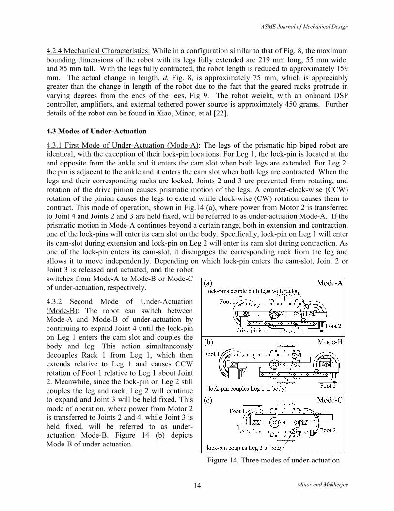
4.3.1 First Mode of Under-Actuation (Mode-A): The legs of the prismatic hip biped robot are identical, with the exception of their lock-pin locations. For Leg 1, the lock-pin is located at the end opposite from the ankle and it enters the cam slot when both legs are extended. For Leg 2, the pin is adjacent to the ankle and it enters the cam slot when both legs are contracted. When the legs and their corresponding racks are locked, Joints 2 and 3 are prevented from rotating, and rotation of the drive pinion causes prismatic motion of the legs. A counter-clock-wise (CCW) rotation of the pinion causes the legs to extend while clock-wise (CW) rotation causes them to contract. This mode of operation, shown in Fig.14 (a), where power from Motor 2 is transferred to Joint 4 and Joints 2 and 3 are held fixed, will be referred to as under-actuation Mode-A. If the prismatic motion in Mode-A continues beyond a certain range, both in extension and contraction, one of the lock-pins will enter its cam slot on the body. Specifically, lock-pin on Leg 1 will enter its cam-slot during extension and lock-pin on Leg 2 will enter its cam slot during contraction. As one of the lock-pin enters its cam-slot, it disengages the corresponding rack from the leg and allows it to move independently. Depending on which lock-pin enters the cam-slot, Joint 2 or Joint 3 is released and actuated, and the robot switches from Mode-A to Mode-B or Mode-C of under-actuation, respectively.
4.3.2 Second Mode of Under-Actuation (Mode-B): The robot can switch between Mode-A and Mode-B of under-actuation by continuing to expand Joint 4 until the lock-pin on Leg 1 enters the cam slot and couples the body and leg. This action simultaneously decouples Rack 1 from Leg 1, which then extends relative to Leg 1 and causes CCW rotation of Foot 1 relative to Leg 1 about Joint 2. Meanwhile, since the lock-pin on Leg 2 still couples the leg and rack, Leg 2 will continue to expand and Joint 3 will be held fixed. This mode of operation, where power from Motor 2 is transferred to Joints 2 and 4, while Joint 3 is held fixed, will be referred to as under-actuation Mode-B. Figure 14 (b) depicts Mode-B of under-actuation.
Figure 14. Three modes of under-actuation
ASME Journal of Mechanical Design
Minor and Mukherjee 15
If the robot is anchored on Foot 1 during Mode-B, the body of the robot will rotate in the CW direction as it expands in length. If the robot is anchored on Foot 2, the robot body will expand but not rotate. Instead, Foot 1 will rotate in the CCW direction. If this is the case, Foot 1 can be anchored after it has turned in the CCW direction by some angle. At this time, reversal in the direction of rotation of the drive pinion will cause Foot 1 to rotate CW relative to the body and contraction of the robot body along Joint 4. Since Foot 1 now provides support, it will result in CCW rotation of the robot. In under-actuation Mode-B, the robot can therefore rotate both in the CW and CCW directions about Joint 2 while standing on Foot 1.
4.3.3 Third Mode of Under-Actuation (Mode-C): If the legs of the robot keep contracting in under-actuation Mode-A, the lock-pin on Leg 2 will enter its cam-slot and couple the body with Leg 2. The leg will simultaneously decouple from Rack 2, which will then move relative to the leg and cause CW rotation of Foot 2. Since the lock-pin on Leg 1 will still couple it with its rack, the robot will continue to contract along Joint 4 while Joint 2 will remain fixed. This mode of operation, where power from Motor 2 will be transferred to Joints 3 and 4, while Joint 2 is held fixed, will be referred to as under-actuation Mode-C. Figure 14 (c) depicts Mode-C of under-actuation. Similar to Mode-B, where the robot can rotate bi-directionally about Joint 2 standing on Foot 1, the robot can rotate bi-directionally about Joint 3 standing on Foot 2 in Mode-C. In our design, the amount of foot rotation possible is 380° for both Mode-B and Mode-C. This is accompanied by change in length of the robot by 21 mm along Joint 4.
4.4 Locomotion Gaits
4.4.1 Crawling: The prismatic hip biped can switch between the three modes of under-actuation, discussed above, to generate two distinct locomotion gaits, namely, Crawling and Pivoting. The crawling gait allows the robot to move through confined passages with a modest pace. The pivoting gait enables faster locomotion in relatively unrestricted environments. Both gaits allow the robot to steer and walk along a straight line on a flat surface, and move between different inclined surfaces.
While using the crawling stride, the robot operates in under-actuation Mode-A to walk along a straight line. Initially perched on one foot, say Foot 1, the robot lifts its body through articulation of its ankle joint, Joint 1. It then expands the body using Mode-A and articulates Joint 1 to lower its body and bring Foot 2 in contact with the walking surface. Once Foot 2 is anchored, the robot articulates Joint 5 to raise the body and lift Foot 1, contract the body using Mode-A, and articulates Joint 5 to bring Foot 1 back in contact with the walking surface. By repeating the procedure, the robot moves along a straight line, covering a net distance of approximately 7.5 cm. A series of snap shots illustrating this walking gait on a vertical surface are shown at the end of the paper in Figure 18. The cross-sectional area normal to the path that is required for the inchworm like gait is only 52.5 cm2. If the robot needs to change direction, it switches to Mode-B or Mode-C, depending on the foot it uses for steering. After steering, it reverts back to Mode-A for motion along a straight line.
In the crawling stride, the prismatic hip biped can steer on either foot, both in the CW and CCW directions. Figure 15 depicts these four cases. To steer in the CW direction on Foot 1, the robot anchors Foot 1 and adopts Mode-B of under-actuation. After steering, the robot switches from Mode-B to Mode-A to continue walking along a straight line. To steer in the CCW direction on Foot 1, the robot anchors itself on Foot 2 and winds up Foot 1 in Mode-B. It then anchors itself
ASME Journal of Mechanical Design
Minor and Mukherjee 16
on Foot 1 to unwind and steer in Mode-B. The angle of steering is limited by the initial angle of windup but since the initial windup can be as large as 380°, the robot can steer in any direction. After steering in the desired direction, the robot switches to Mode-A and continues to walk along a straight line.
The steering action on Foot 2 is similar to steering on Foot 1 with the exception that the robot switches between Mode-A and Mode-C of under-actuation. To steer in the CW direction, the robot anchors itself on Foot 1 and winds up Foot 2 in Mode-C. It then anchors itself on Foot 2 to unwind and steer in Mode-C. After steering in the desired direction, the robot reverts to Mode-A and continues walking along a straight line. To steer in the CCW direction, the robot anchors Foot 2 and adopts Mode-C of under-actuation. After steering, the robot switches to Mode-A to continue walking along a straight line. Snapshots illustrating the robot maneuvering a passageway using a combination of walking and steering techniques are shown in Figure 19 at the end of the paper.
Figure 15. Steering capabilities of the prismatic hip biped
ASME Journal of Mechanical Design
Minor and Mukherjee 17
Apart from walking and steering on a flat surface, the robot can move between inclined surfaces using the crawling gait. To move between arbitrarily inclined surfaces, the robot adopts Mode-A for expanding or contracting its length along Joint 4 and articulates Joints 1 and 5 to properly orient the foot to be anchored. The crawling gait has been demonstrated experimentally while walking on flat and inclined surfaces, and while climbing between surfaces with different inclinations. Further details on these results can be found in Xiao, Minor, et al [22].
4.4.2 Pivoting: The pivoting gait employs all three modes of under-actuation to generate a faster stride. Consider the robot to be initially supported by Foot 2 and in Mode-C of under-actuation, as in Fig.16 (a). In this configuration, the robot lifts its body by articulating Joint 5, and rotates its body about Joint 3. After 180° rotation, the robot lowers its body by articulating Joint 5 and anchors Foot 1 on the walking surface. It then switches from Mode-C to Mode-A and expands its body along Joint 4. After full extension of the body, it switches from Mode-A to Mode-B. At this time, the robot lifts its body by articulating Joint 1 and rotates the body by 180°. Subsequently, it lowers its body by articulating Joint 1 and anchors Foot 2 on the walking surface. By repeating the procedure of alternately pivoting on Foot 1 and Foot 2, the robot essentially walks along a straight line. After the pivoting actions about both feet, the result is that Foot 2 has traveled a distance of 15.5 cm along the line of motion. The distance traveled is twice as large as that of the crawling stride, but the cross-sectional area required for the maneuver is approximately five times greater, or 250 cm2. The excessive space required for the maneuver should however not be construed as a disadvantage since the pivoting gait will be employed in open environments only. Apart from walking along a straight line, the robot can steer in the pivoting gait by turning an angle different from 180°, as shown in Fig.16 (b). Since the robot alternately pivots on both feet, steering is possible on either foot. Intermediate step lengths as small as a few mm can similarly be achieved by rotating less than 180° during the walking pivoting gait shown in Fig.16 (a), but the crawling stride described previously is much more efficient in terms of space usage and complexity of motion.
Figure 16. Walking and steering using the pivoting gait
ASME Journal of Mechanical Design
Minor and Mukherjee 18
5. Conclusion
In this paper we addressed the problem of autonomous climbing robot design for reconnaissance applications. While such applications require robots to avoid detection and impose constraints on their size, autonomous capability require self-sufficiency and pose the problem of excess weight. In the absence of a better alternative, suction mechanisms were used in our design for providing grasping capability. This compounds the problem since miniature suction mechanisms have very limited capacity of supporting weight. In the presence of stringent size and space constraints, the design challenge was addressed by using under-actuated kinematic structures that reduce weight by using fewer actuators, but provide full range of mobility. Two designs were presented based on the biped morphology. The first design is quite simple and uses three actuators to drive four revolute joints. Through kinematic coupling of two joints, the number of actuators is reduced and the robot is predisposed to a cartwheel style gait. The cartwheel gait requires significant space for maneuvering and generates large moments on the suction mechanisms. These disadvantages are overcome in the second design, which advocates a new concept of under-actuation. In this design, the robot operates in three discrete modes of under-actuation and switches between the modes to adopt one of two specialized gaits. The robot adopts the crawling gait to pass through narrow passages and a faster pivoting gait in relatively open environments. Climbing robots were manufactured based on both designs, and they amply demonstrated their full range of mobility. In concert with the applications for which they are intended, the robots are indeed significantly smaller than many of those that can be referenced in the literature. Our future research is aimed at further miniaturization of climbing robots, development of kinematic structures with improved adaptability, and providing existing climbing robots the ability to climb surfaces with undulations and imperfections.
Acknowledgement This work was supported by the Defense Advanced Research Projects Agency, DARPA Contract No. DAANO2-98-C-4025.
ASME Journal of Mechanical Design
Minor and Mukherjee 19
(a) Start on Foot 2
(b) Lifting Foot 1
(c) Lifting Foot 1
(d) Foot 1 contacts surface
(e) Foot 2 releases
(f) Transition complete
Figure 17. Revolute hip biped crossing from a vertical surface to a horizontal ceiling
(a) Start
(b) Lift Foot 2
(c) Contract
Body
(d) Lower
Foot 2
(e) Lift Foot 1
(f) Expand
Body
(g) Lower
Foot 1 Figure 18. Prismatic hip robot climbing a wall
(a) Start: contracted.
(b) Expand body
(c) Contract legs
(d) Rotate
(e) Unwind foot
(f) Expand legs
(g) Contract legs
(h) Rotate
(i) Unwind foot
(j) Expand legs
(k) Contract legs
(l) Rotate
(m) Unwind foot
(n) Contract legs
(o) Expand legs
Figure 19. Prismatic hip robot turning a corner
ASME Journal of Mechanical Design
Minor and Mukherjee 20
References 1. Bergerman, M., C. Lee, and Y. Xu, "Experimental study of an underactuated
manipulator", Proceedings of the 1995 IEEE/RSJ International Conference on Intelligent Robots and Systems, Pittsburgh, PA., 2, p317-322, 1995.
2. Spong, M.W., "Partial feedback linearization of underactuated mechanical systems", Proceedings of the IEEE/RSJ/GI International Conference on Intelligent Robots and Systems, Munich, Ger., 1, p314-321, 1994.
3. Greenwood, D.T., Principles of Dynamics, Englewood Cliff, NJ.: Prentice Hall, 1988. 4. Nakamura, Y. and R. Mukherjee, "Nonholonomic path planning of space robots via a
bidirectional approach," IEEE Transactions on Robotics and Automation, 7(4), p500-514, 1991.
5. Mukherjee, R. and M. Kamon, "Almost smooth time-invariant control of planar space multibody systems," IEEE Transactions on Robotics and Automation, 15(2), p268-280, 1999.
6. Kolmanovsky, I. and N.H. McClamroch, "Developments in nonholonomic control problems," IEEE Control Systems Magazine, p20-36, 1995.
7. Bullo, F. and N.E. Leonard, "Motion primitives for stabilization and control of underactuated vehicles", 4th IFAC Nonlinear Control Systems Design Symposium 1998. NOLCOS '98, Enschede, Netherlands, 1, p133-138, 1998.
8. Fossen, T.L., J.-M. Godhavn, S.P. Berge, and K.-P. Lindegaard, "Nonlinear control of underactuated ships with forward speed compensation", Preprints of the 4th IFAC Nonlinear Control Systems Design Symposium 1998. NOLCOS '98, Enschede, Netherlands, 1, p121-126, 1998.
9. Pei, H.-L. and Y. Xu, "Control of underactuated free floating robots in space", Proceedings of the 1998 IEEE/RSJ International Conference on Intelligent Robots and Systems, Victoria, Can., 2, p1364-1369, 1998.
10. Mukherjee, R. and D. Chen, "Control of free-flying underactuated space manipulators to equilibrium manifolds," IEEE Transactions on Robotics and Automation, 9(5), p561-570, 1993.
11. Jain, A. and G. Rodriguez, "Analysis of the kinematics and dynamics of underactuated manipulators," IEEE Transactions on Robotics and Automation, 9(4), p411-422, 1993.
12. Arai, H., K. Tanie, and N. Shiroma, "Time-scaling control of an underactuated manipulator," Journal of Robotic Systems, 15(9), p525-36, 1998.
13. Yu, K.-H., Y. Shito, and H. Inooka, "Position control of an underactuated manipulator using joint friction," International Journal of Non-Linear Mechanics, 33(4), p607-614, 1998.
14. de Luca, A. and G. Oriolo, "Motion planning and trajectory control of an underactuated three-link robot via dynamic feedback linearization", Proceedings 2000 IEEE International Conference on Robotics and Automation, San Francisco, CA., 3, p2789-2795, 2000.
15. Fantoni, I., R. Lozano, and M.W. Spong, "Energy based control of the Pendubot," IEEE Transactions on Automatic Control, 45(4), p725-729, 2000.
16. Ramos, L.E., B. Castillo-Toledo, and J. Alvarez, "Nonlinear regulation of an underactuated system", Proceedings of the 1997 IEEE International Conference on Robotics and Automation, Albuquerque, NM., 4, p3288-3293, 1997.
ASME Journal of Mechanical Design
Minor and Mukherjee 21
17. McGeer, T., "Passive Dynamic Walking," International Journal of Robotics Research, 9(2), p62-82, 1990.
18. Moran, A., H. Odagaki, and M. Hayase, "Dynamics and control of underactuated brachiation robots", Proceedings of the 1997 1st IEEE/ASME International Conference on Advanced Intelligent Mechatronics, AIM'97, Tokyo, Jpn., p98, 1997.
19. Nakanishi, J., T. Fukuda, and D.E. Koditschek, "Brachiating robot controller," IEEE Transactions on Robotics and Automation, 16(2), p109-123, 2000.
20. Yue, M., N. Xi, M. Minor, and R. Mukherjee, "Dynamic workspace analysis and motion planning for a micro biped walking robot", Proceedings. 2000 IEEE/RSJ International Conference on Intelligent Robots and Systems (IROS 2000), Piscataway, NJ, USA, 3, p1900-5, 2000.
21. Yue, M., M. Minor, N. Xi, and R. Mukherjee, "Kinematics Workspace Analyses of a Miniature Walking Robot", Proc. 1999 IEEE/RSJ International Conference on Intelligent Robots and Systems, Kyongju, Korea, p1798-1803, 1999.
22. Xiao, J., M. Minor, H. Dulimarta, N. Xi, R. Mukherjee, and R.L. Tummala, "Modeling and control of an under-actuated miniature crawler robot", Proceedings of RSJ/IEEE International Conference on Intelligent Robots and Systems, Piscataway, NJ, USA, 3, p1546-51, 2001.
23. Guo, G., W.A. Gruver, and X. Qian, "A new design for a dexterous robotic hand mechanism," IEEE Control Systems Magazine, 12(4), p35-38, 1992.
24. Minor, M. and R. Mukherjee, "Mechanism for dexterous end-effector placement during minimally invasive surgery," Journal of Mechanical Design, Transactions of the ASME, 121(4), p472-479, 1999.
25. Hirose, S. and M. Sato, "Coupled Drive of the Multi-DOF Robot", IEEE International Conference on Robotics and Automation - 1989, Scottsdale, AZ., p1610-1616, 1989.
26. Hirose, S. and K. Arikawa, "Coupled and decoupled actuation of robotic mechanisms", ICRA 2000: IEEE International Conference on Robotics and Automation, San Francisco, Ca., p33-39, 2000.
27. Hirose, S., A. Nagakubo, and R. Toyama, "Machine That Can Walk and Climb on Floors, Walls, and Ceilings", Fifth International Conference on Advanced Robotics, p753-758, 1991.
28. Luk, B., A. Collie, and J. Billingsley, "Robug II: An intelligent wall climbing robot", Proceedings of the 1991 IEEE International Conference on Robotics and Automation, Sacramento, Ca., p2342-2347, 1991.
29. Bahr, B., Y. Li, and M. Najafi, "Design and Suction Cup Analysis of a Wall Climbing Robot," Computers & Electrical Engineering, 22(3), p193-209, 1996.
30. Ikeda, K., T. Nozaki, and S. Shimada, "Development of a Self-contained Wall Climbing Robot," Journal of Mechanical Engineering Laboratory, 46(2), p128-137, 1992.
31. Luk, B.L., A.A. Collie, V. Piefort, and G.S. Virk, "Robug III: A Tele-operated Climbing and Walking Robot", IEE Conference Publication, Proceedings of the 1996 UKACC International Conference on Control, Stevenage, Engl., 1, p347-352, 1996.
32. Pack, R.T., J.L. Christopher, and K. Kawamura, "A Rubbertuator-Based Structure-Climbing Inspection Robot", Proceedings of the 1997 IEEE International Conference on Robotics and Automation, ICRA., Albuquerque, NM., 3, p1869-74, 1997.
ASME Journal of Mechanical Design
Minor and Mukherjee 22
33. Kotay, K.D. and D.L. Rus, "Navigating 3D steel web structures with an inchworm robot", Proceedings of IEEE/RSJ International Conference on Intelligent Robots and Systems. IROS '96, New York, NY, USA, 1, p368-75, 1996.
34. Nishi, A., "A Biped Walking Robot Capable of Moving on a Vertical Wall," Mechatronics, 2(6), p543-554, 1992.
35. Yano, T., T. Suwa, M. Murakami, and T. Yamamoto, "Development of a Semi Self-Contained Wall Climbing Robot with Scanning Type Suction Cups", Proceedings of the 1997 IEEE/RSJ International Conference on Intelligent Robot and Systems, Grenoble, Fr., 2, p900-905, 1997.
36. Kotay, K.D. and D.L. Rus, "Task-reconfigurable robots: navigators and manipulators", Proceedings of the 1997 IEEE/RSJ International Conference on Intelligent Robot and Systems. Innovative Robotics for Real-World Applications. IROS '97, New York, NY, USA, 2, p1081-9, 1997.
37. Castano, A. and P. Will, "Mechanical design of a module for reconfigurable robots", Proceedings. 2000 IEEE/RSJ International Conference on Intelligent Robots and Systems (IROS 2000), Piscataway, NJ, USA, 3, p2203-9, 2000.
38. Yim, M., D.G. Duff, and K.D. Roufas, "PolyBot: a modular reconfigurable robot", Proceedings 2000 ICRA. IEEE International Conference on Robotics and Automation, Piscataway, NJ, USA, p514-20, 2000.
39. Murata, S., E. Yoshida, K. Tomita, H. Kurokawa, A. Kamimura, and S. Kokaji, "Hardware design of modular robotic system", Proceedings. 2000 IEEE/RSJ International Conference on Intelligent Robots and Systems (IROS 2000), Piscataway, NJ, USA, 3, p2210-17, 2000.
40. White, T.S., N. Hewer, B.L. Luk, and J. Hazel, "Design and Operational Performance of a climbing robot used for weld inspection in hazardous environments." Proceedings of the 1998 IEEE International Conference on Control Applications, Trieste, Italy, p451-455, 1998.
41. Briones, L., P. Bustamante, and M. Serna, "Robicen: A wall climbing pneumatic robot for inspection in nuclear power plants," Robotics & Computer-Integrated Manufacturing, 11(4), p287-292, 1994.
42. Bach, F.-W., H. Haferkamp, J. Lindemaier, and M. Rachkov, "Underwater Climbing Robot for contact Arc Metal Drilling and Cutting." Proceedings of the 1996 IEEE 22nd International Conference on Industrial Electronics, Control, and Instrumentation, IECON, Taipei, Taiwan, 3, p1560-1565, 1996.
43. Nishi, A., "Development of Wall Climbing Robots," Computers & Electrical Engineering, 22(2), p123-149, 1996.
44. Hirose, S. and H. Tsutsumitake, "Disk Rover: A Wall-Climbing Robot using Permanent Magnet Disks", Proceedings. 1992 lEEE/RSJ International Conference on Intelligent Robots and Systems, Raleigh, NC., 3, p2074-2079, 1992.
45. Dangi, G., J. Stam, and D. Aslam, "Design, Fabrication, and Testing of a Smart Robotic Foot for Microrobotic Systems", Proceedings of the 31st International Symposium on Robotics (ISR 2000), Montreal, Que., Canada, p283-287, 2000.
46. Minor, M.A., Design and Control of Constrained Robotic Systems for Enhanced Dexterity and Mobility, Ph.D. Dissertation, Michigan State University, East Lansing, MI, 2000.
ASME Journal of Mechanical Design
Minor and Mukherjee 23
47. Minor, M., H. Dulimarta, G. Danghi, R. Mukherjee, R. Lal Tummala, and D. Aslam, "Design, implementation, and evaluation of an under-actuated miniature biped climbing robot", Proceedings. 2000 IEEE/RSJ International Conference on Intelligent Robots and Systems (IROS 2000), Piscataway, NJ, USA, 3, p1999-2005, 2000.