28
Underground Commercial Electric Service © SCANA Corporation 2018 Revised: February 2019

Underground Commercial Electric Service
© SCANA Corporation 2018
Revised: February 2019

Table of Contents
Underground Commercial Electric Service
Section 1: Specifications and Requirements
General ...................................................................................................................2 Definition of Terms ..................................................................................................2 Company and Developer’s Responsibilities Defined ...............................................3 Reimbursement .......................................................................................................6
Section 2: Underground Commercial Service ....................................................7
Section 3: Design Considerations
Transformer Bank and Dip Location ........................................................................8 Truck Access ...........................................................................................................8 Customer Ground Conductor ..................................................................................8 Pad Mount Transformer Location ............................................................................8 Fuel Storage Clearance ..........................................................................................8
Section 4: Construction Details and Coordination
Foreign Utilities and Obstructions ...........................................................................9 Right-of-Way ...........................................................................................................9 Trench Excavation and Backfill ...............................................................................9
Section 5: Construction Drawings .......................................................................10
© SCANA Corporation 2018 1

Section 1: Specifications and Requirements
A. General
These specifications and requirements for South Carolina Electric & Gas Company and the Developer, which are general in nature, cover the material, construction, workmanship and procedures for the typical installation of underground electrical facilities to new commercial projects. The method of feed shall be at the discretion of South Carolina Electric & Gas Company. The developer/owner should contact the Company as soon possible in the planning stage of the project to address electrical service issues such as voltage, service point, etc.
B. Definition of Terms
1) The term “Company” when used herein means South Carolina Electric & GasCompany.
2) The term “Developer” when used herein means the party entering into theagreement with the Company.
3) “Radial service” shall mean a cable connected to an overhead line (or other sourceof electrical energy) extending down the pole and under the ground to one or moretransformers together with the necessary accessories to assure proper operation.
4) “Loop service” shall mean a cable extending from an overhead line down the pole(or other source of electrical energy) under the ground to a transformer, extended(or looped) to additional transformers one at a time, then extended to and upanother pole to an overhead line. Such service may have a normally open point,as Company may deem appropriate.
5) “Underground secondary service” shall mean secondary service wires furnished,installed, owned and maintained by the customer which run from transformer(overhead or pad-mount) or other point of service (i.e.; hand-hole, Company ownedpole, Customer owned pole, etc) identified by Company to customer’s load center.
6) “Foreign Utility” shall mean any electric, gas, communication, water, sewer,drainage or other utility not owned by SCE&G Co.
© SCANA Corporation 2018 2

C. Company and Developer’s Responsibilities Defined
1) In order to receive electric service, the Developer shall:
a) Furnish (at no cost to the Company) an acceptable drawing or plat (electronicformat is standard) showing details of property lines, buildings, dedicatedeasements, sediment and erosion control measures, water lines, sewage,drainage, any other underground facilities and a grading plan showing initial andfinal contours. Environmentally sensitive areas must be shown on proposedlayouts (wetlands, bodies of water, cemeteries, historical sites, etc.)
b) Coordinate the approval of governmental agencies required for the development(i.e.; buffer zones, wetlands, zoning, land disturbance, etc.)
c) Provide suitable easements for electrical service including restrictions for theelimination of encroachments, which may interfere with the continued operationand maintenance of the underground electric facilities.
d) Specify the length of time anticipated for the completion of the project (includingeach stage or phase of development when known) and provide the date’stemporary and permanent electric service is required. Coordinate major schedulechanges with the Company. Furnish technical details of electrical service needsincluding voltages, size and type of connected loads and similar data.
e) Install and maintain permanent property corners prior to the start of work by theCompany.
f) Initiate stabilization measures as required both before and after installation ofunderground lines and include this activity in sequencing of construction activitiesin the Storm Water Pollution Prevention Plan. Developer will be responsible fortemporary stabilization, if necessary, once final grade is established and prior toCompany trenching activities. Do not initiate final stabilization on easement priorto Company installing underground lines. Any inlet protection will be responsibilityof the developer.
g) Establish final grade and tamp any required filling or grading before the start of anyunderground distribution construction. Costs incurred due to changes in earthgrades after the start of construction will be borne by the Developer.
h) Furnish, install, own and maintain the concrete transformer pad and vehicular
© SCANA Corporation 2018 3

protection bollards, if required. Furnish and install all necessary conduits, pull wire, pull boxes, bends, including necessary trenching and back filling, in accordance with Company drawings and specifications, from the transformer location to the source. This shall include galvanized bends, transformer entrance conduit and the first section of PVC SCH40 conduit up the pole. Installation by the Developer shall comply with Company drawing 06.04-08 and be subject to Company acceptance.
i) Furnish, install, own, and maintain the meter base for services served by atransformer capacity of 150 KVA or less. Transformer capacity will be based onexpected load rather than main disconnect size. Services larger than those listedabove will generally be metered using current transformers. Note – This is ageneral guideline only; Company Metering Department should be consulted toconfirm proper equipment needed for each situation. These guidelines are subjectto change as metering technology changes.
j) Keep the transformer and primary cable unencumbered and accessible formaintenance and provide suitable vehicular barriers where required per Companydrawing 17.02-01D.
k) Notify Palmetto Utility Protection Service (811) for marking of underground facilitiesprior to digging. Hand dig foreign utility trenches in areas crossing electrical cablesalready in place to eliminate contact with electrical cables.
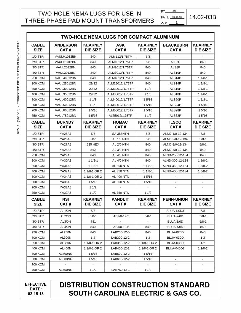
l) Furnish and install secondary conduit and conductors, including connectors forconnection at service point. Required service conductor sizes are 1/0 through 750KCMIL stranded copper or 1/0 through 750 KCMIL stranded aluminum cables ormultiple conductors of these sizes. Connectors for use in pad mount transformersshall be 2-hole compression, lug type, as specified on drawings 14.02-03A, 14.02-03B and 14.02-03C.
m) Take service at the service point identified by the Company. For pad mounttransformers, the number of secondary service connections is limited to themaximum as shown on the tables in drawing 17.02-01C. Secondary servicecables shall comply with the National Electrical Code, current edition, as aminimum when installed. Secondary cables carrying metered energy shall beinstalled in separate conduit or raceways from all other cables or wires.
n) Furnish, install, operate and maintain phase converters for three phase loads(where Developer has elected not to utilize single phase) in areas with only single
© SCANA Corporation 2018 4

phase available. Developer can elect to pay a difference in cost and monthly operating fee for three phase service in lieu of installing phase converter.
o) The developer will be fully responsible for compliance with any tree or bufferordinances affecting SCE&G easements. Any funding or tree replacement will bethe responsibility of the developer. Buffer requirements are in addition to andseparate from SCE&G easements. The developer shall be fully aware of allappropriate ordinances that can affect SCE&G's right of way and should take thisinto account when assigning the easement.
p) The developer shall be fully responsible, as required by local ordinances, toestablish and maintain tree barricades around all trees required to be preserved.Any required barricades shall be in place prior to SCE&G beginning design orinstallation of underground facilities. The standard method of construction will beby an open-trench (trencher or back hoe). Any encroachments in barricaded areaswill require directional bores to protect trees and shall be considered as non-standard service to the developer and at the developer’s expense. The developershall be solely responsible and liable for any tree damages incurred during theinstallation of underground electric facilities that are caused by the developer’sfailure to properly barricade any significant trees, as prescribed by localordinances.
The developer will be responsible for coordination of the approval of governmental agencies required for the development (i.e.; buffer zones, wetlands, storm water permitting, zoning, etc.)
Wetlands
Provide official verification and confirmation of the wetlands and permits that have been issued, as stated in a letter from the U.S. Army Corps of Engineers (USACE). The letter must reference the detailed site plan drawing (same dated version) and include a file number. Stake or mark the wetlands boundaries prior to construction by SCE&G. If unable to provide the above information, SCE&G will provide a Wetlands Determination Authorization Form for developer to sign giving SCE&G permission to have the impacted property surveyed for jurisdictional wetlands, which could include the USACE entering the property. Any costs associated with survey and resulting delineation required will be at developer’s expense.
© SCANA Corporation 2018 5

Storm Water
Obtain coverage under the NPDES General Permit for Storm Water Discharges from Construction Activities for all easements and areas of electric line construction and provide official verification of this coverage. Provide site maps showing the locations of all sediment and erosion control measures planned for electric line construction and include these areas in the Storm Water Pollution Prevention Plan.
Developer will be responsible for installation, maintenance, and inspection of all sediment and erosion control measures around electric lines. Notice of Termination will not be submitted by Developer prior to Company completing all electric line installation.
2) The Company shall:
a) Furnish, install, connect, own and maintain all required overhead facilities, primarycables, and the pad mount transformer. Metering facilities will be installed atlocations approved by the Company. Connecting these metering facilities shall behandled on an individual basis.
b) Prepare an electrical distribution layout for Developer’s approval prior toconstruction. The layout will be the Developer’s plat, drawing or other informationincluded in paragraph C 1 (a) above. If changes requested by the Developer afterapproval result in additional expenses, the Developer shall bear these additionalexpenses, including reimbursement to the Company for all changes.
c) Supply the Developer a copy of the approved print prior to beginning construction.
D. Reimbursement
The Developer may be required to pay the Company for the cost of facilities installed in excess of standard as determined by the Company. The Developer may also be required to pay a contribution in aid of construction for projects where the construction cost to expected revenue ratio is above a level set by the Company. This will be in addition to the charge for non-standard service. An estimate of the amount of such reimbursement will be made available to the customer upon request before work begins. All designs must be analyzed by Company engineers. The Developer will be required to reimburse the Company for all costs associated with all changes made at the Developer’s request to the electrical distribution layout after it is approved by the Developer and the Company.
© SCANA Corporation 2018 6

Section 2: Underground Commercial Service
A) The standard method for providing commercial underground service will be from anoverhead transformer bank with an underground service (reference drawings 06.04-06 and 06.04-07. Underground secondary service will be furnished, installed, ownedand maintained by the customer.
B) The Company may elect to use underground primary and a pad mount transformerfor large loads or in all-underground areas. The maximum length of undergroundprimary from dip pole or switchgear to a pad mount transformer is 300 feet.
C) Requests for underground primary, pad mount transformers, loop feeds, or other non-standard service will be considered, but the customer will be expected to pay thedifference in cost in excess of standard service as well as a monthly operating fee forthese facilities.
D) The customer’s request for underground service is subject to Company review andapproval.
E) Some of these conditions may not apply to customers served from a network or totallyunderground system. These situations will be handled on an individual basis.
F) These conditions also may not apply when, in the opinion of the Company, theelectrical demand exceeds 2500 KVA or other conditions dictate the need for a specialdesign or substation. These situations will also be handled on an individual basis.
© SCANA Corporation 2018 7
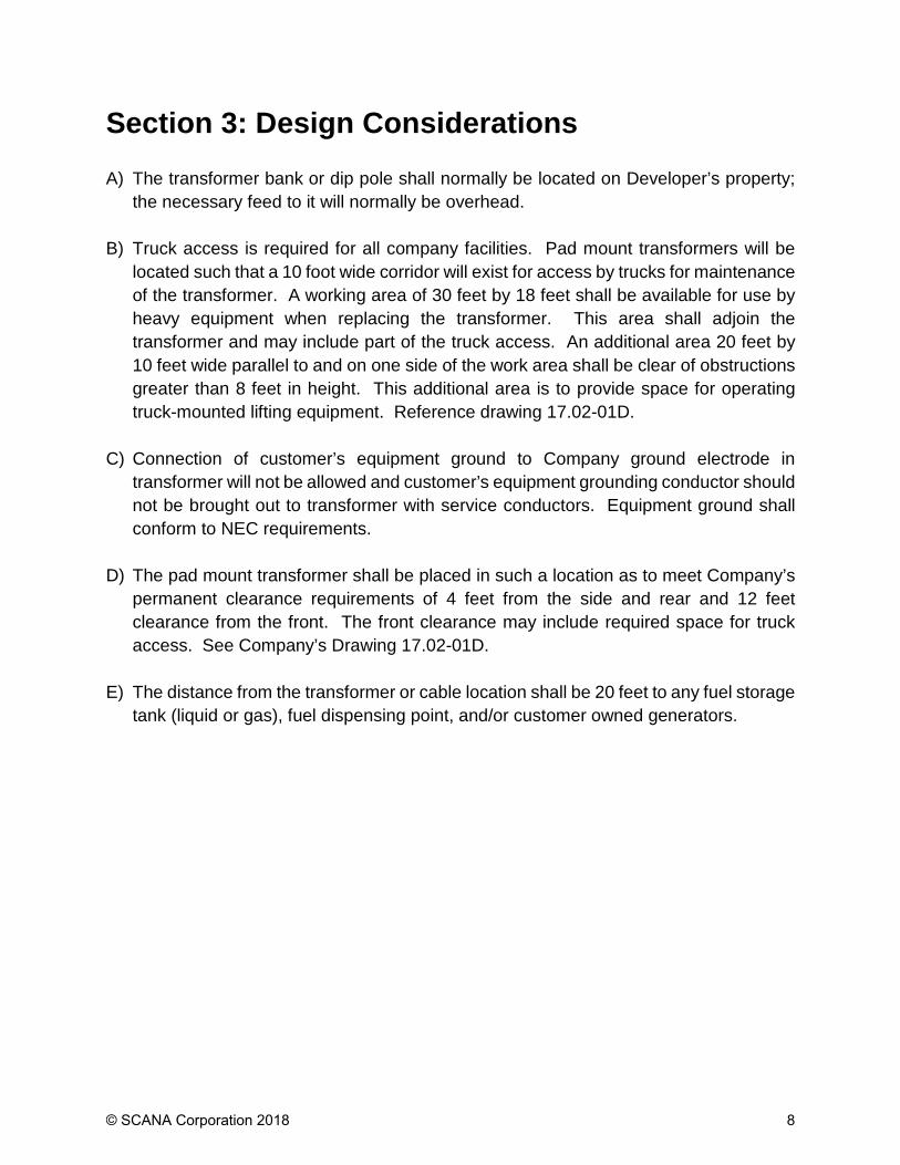
Section 3: Design Considerations
A) The transformer bank or dip pole shall normally be located on Developer’s property;the necessary feed to it will normally be overhead.
B) Truck access is required for all company facilities. Pad mount transformers will belocated such that a 10 foot wide corridor will exist for access by trucks for maintenanceof the transformer. A working area of 30 feet by 18 feet shall be available for use byheavy equipment when replacing the transformer. This area shall adjoin thetransformer and may include part of the truck access. An additional area 20 feet by10 feet wide parallel to and on one side of the work area shall be clear of obstructionsgreater than 8 feet in height. This additional area is to provide space for operatingtruck-mounted lifting equipment. Reference drawing 17.02-01D.
C) Connection of customer’s equipment ground to Company ground electrode intransformer will not be allowed and customer’s equipment grounding conductor shouldnot be brought out to transformer with service conductors. Equipment ground shallconform to NEC requirements.
D) The pad mount transformer shall be placed in such a location as to meet Company’spermanent clearance requirements of 4 feet from the side and rear and 12 feetclearance from the front. The front clearance may include required space for truckaccess. See Company’s Drawing 17.02-01D.
E) The distance from the transformer or cable location shall be 20 feet to any fuel storagetank (liquid or gas), fuel dispensing point, and/or customer owned generators.
© SCANA Corporation 2018 8

Section 4: Construction Details and Coordination Installation of underground electric service facilities shall be performed in accordance with plans and specifications furnished by the Company. The following stipulations are made to clarify certain details of the trenching and backfilling agreements involving the Company and the Developer. 1) Foreign Utilities and Obstructions
Field determination of the locations and elevations of all foreign utilities and obstructions in areas of conflict with primary and secondary cables and transformer pads shall be performed by the Developer. The location of all crossing facilities shall be clearly marked by the Developer. See drawing 16.01-05.
2) Right-of-Way
Construction will not begin until satisfactory rights-of-way (including easements) are made available to Company. Developer is responsible for all stabilization requirements, sediment and erosion control measures, and clean up of debris from right-of-way clearing operations to include but not limited to limbs, trees and stumps. Company will utilize proper installation techniques, but is not responsible for damage to landscape, bodies of water, trees or flora during installation of facilities. Obstructions to the performance of Company work such as construction materials and equipment shall have been cleared away by the Developer prior to the start of Company construction.
3) Trench Excavation and Backfill
Trench excavation and backfill is the responsibility of the Developer. It is the Developer’s responsibility to ensure compliance with OSHA and other Federal, State and local requirements while doing this work. Backfill shall be dirt, sand, or soil excavated from the trench, or other suitable soils, free from rock, organic materials, construction materials or other debris.
© SCANA Corporation 2018 9
Section 5: Construction Drawings Drawing Title 06.04-06 .................... Commercial Hybrid Service on SCE&G Pole 06.04-07 .................... Commercial Hybrid Service on Customer Pole 06.04-08 .................... Commercial Requirements for Pad Mount Transformer Service 12.01-04 .................... Pad Mount Switchgear Clearance Requirements 14.02-03A .................. Two-Hole Nema Lugs for 3Φ Pad Mount Transformers 14.02-03B .................. Two-Hole Nema Lugs for 3Φ Pad Mount Transformers 14.02-03C ................. Two-Hole Nema Lugs for 3Φ Pad Mount Transformers 16.01-04 .................... Joint Use with Communication & Gas at Transformer Locations 16.01-05 .................... Non-Joint Use Trenching Detail 16.01-06 .................... Road Crossing Detail 17.02-01A .................. Radial Feed 3Φ Transformer Concrete Pad Detail 17.02-01B .................. Loop Feed 3Φ Transformer Concrete Pad Detail 17.02-01C ................. 3Φ Transformer Concrete Pad Supplemental Details 17.02-01D ................. Guide for Locating/Spotting 3Φ Pad Mount Transformer 19.01-03 .................... Meter Clearance Requirements 19.01-04 .................... Meter Socket Mounting Configurations 19.01-05 .................... Modular (Ganged) Meter Assembly
© SCANA Corporation 2018 10

COMMERCIAL HYBRID
SERVICE ON SCE&G POLE
JAL
07-10-17
1
06.04-06
DISTRIBUTION CONSTRUCTION STANDARD
SOUTH CAROLINA ELECTRIC & GAS CO.
EFFECTIVE
DATE:
08-07-17
NOTES:
1. SEE DRAWINGS 06.01-01 AND 06.01-02 FOR GENERAL INFORMATION AND NOTES.
2. HANDHOLE OR SECONDARY CABINET LOCATION WILL BE DETERMINED BY SCE&G
REPRESENTATIVE. SEE SECTION 13 FOR SECONDARY ENCLOSURES AND HANDHOLES.
3. SCE&G WILL INSTALL CONDUIT AND CONDUCTOR FROM TRANSFORMER TO HANDHOLE OR
SECONDARY CABINET.
4. THE CUSTOMER'S POINT OF SERVICE IS THE HANDHOLE OR SECONDARY CABINET. CUSTOMER
WILL INSTALL CONDUIT AND CONDUCTOR FROM METER BASE TO THE HANDHOLE OR
SECONDARY CABINET.
5. METERING, SELF-CONTAINED OR CT, WILL BE DETERMINED BY SCE&G METERING DEPARTMENT.
TYPICALLY ANY DEMAND ABOVE 150 KVA REQUIRES CT METERING. CONTACT METERING
DEPARTMENT FOR RECOMMENDATION.
6. SEE DRAWING 07.02-01 FOR REQUIRED FOREIGN ATTACHMENT CLEARANCES.
30"
12"
12"
CUSTOMER BUILDING / FACILITY
CLEARANCE DISTANCE
DETERMINED BY SCE&G
REPRESENTATIVE
SCE&G
NEUTRAL
SEE NOTE 2
SEE NOTE 4
SEE NOTE 3
SEE NOTE 5
RE
V. 1 (07/10/17) - U
PD
AT
ED
S
EC
TIO
N R
EF
ER
EN
CE
IN
N
OT
E 2

COMMERCIAL HYBRID SERVICE
ON CUSTOMER POLE
JAL
11-15-16
0
06.04-07F
OR
ME
RLY
D
WG
# H
UG
S, S
2
DISTRIBUTION CONSTRUCTION STANDARD
SOUTH CAROLINA ELECTRIC & GAS CO.
EFFECTIVE
DATE:
01-15-17
NOTES:
1. CUSTOMER TO INSTALL CUSTOMER OWNED POLE, CONDUIT, WEATHERHEAD AND
CONDUCTOR.
2. SCE&G POINT OF SERVICE TO CUSTOMER IS CUSTOMER OWNED POLE.
3. CUSTOMER TO PROVIDE 6 FEET PIGTAIL AT CONDUIT WEATHERHEAD.
4. SCE&G WILL CONNECT CUSTOMER SERVICE WIRE TO SCE&G SERVICE WIRE.
5. METERING, SELF-CONTAINED OR CT, WILL BE DETERMINED BY SCE&G METERING
DEPARTMENT. TYPICALLY ANY DEMAND ABOVE 150 KVA REQUIRES CT METERING.
CONTACT METERING DEPARTMENT FOR RECOMMENDATION.
6. SEE DRAWING 07.02-01 FOR REQUIRED FOREIGN ATTACHMENT CLEARANCES.
12"
CUSTOMER BUILDING/FACILITY
CUSTOMER OWNED POLE, CONDUIT AND CONDUCTOR
(SEE NOTE 1)
10' - 20'
RECOMMENDED
ALTERNATE
METER LOCATION
(SEE NOTE 5)
CUSTOMER OWNED & MAINTAINED
CONDUIT AND CONDUCTOR
SCE&G POLE SEE NOTE 3

CUSTOMER REQUIREMENTS FOR
PAD MOUNT TRANSFORMER SERVICE
JAL
09-20-17
2
06.04-08
DISTRIBUTION CONSTRUCTION STANDARD
SOUTH CAROLINA ELECTRIC & GAS CO.
EFFECTIVE
DATE:
02-15-18
X0 X1 X2 X3
2
3
4
5
6
10
8
7
1
9
NOTES
A. ITEMS 3, 9 & 10 WILL BE FURNISHED AND INSTALLED BY THE
CUSTOMER TO SCE&G SPECIFICATIONS. CONDUIT(S) MUST BE FREE
OF DEBRIS. ANY IMPROPERLY INSTALLED ITEM CAUSING SCE&G TO
CORRECT COULD REQUIRE REIMBURSEMENT.
B. ITEMS 1, 2, 4, 7 & 8 WILL BE FURNISHED, INSTALLED AND MAINTAINED
BY SCE&G.
C. ITEM 5 WILL BE FURNISHED BY THE CUSTOMER AND INSTALLED BY
SCE&G.
D. ITEM 6 WILL BE FURNISHED, INSTALLED AND MAINTAINED BY THE
CUSTOMER.
E. THE RISER CONDUIT (ITEM 10) SHOULD BE ATTACHED TO THE POLE
OPPOSITE ONCOMING TRAFFIC. EXACT LOCATION SHOULD BE
SPOTTED BY SCE&G PRIOR TO INSTALLATION.
F. ALL METAL (CONDUCTING) CONDUITS LOCATED WITHIN THE
TRANSFORMER MUST BE BONDED TO SCE&G GROUND ROD AND
SYSTEM NEUTRAL.
ITEMS
1. SCE&G PRIMARY DIP POLE
2. SCE&G PRIMARY CABLE AND ACCESSORIES
3. CONCRETE TRANSFORMER PAD
(SEE DRAWINGS 17.02-01A - 17.02-01D)
4. THREE PHASE PAD-MOUNT TRANSFORMER
5. CUSTOMER SERVICE CABLE CONNECTORS
(SEE DRAWINGS 14.02-03A - 14.02-03C)
6. CUSTOMER SERVICE CONDUIT AND CONDUCTORS
7. GROUND RODS
8. GALVANIZED IRON CONDUIT U-GUARD
(6" X 5' OR AS SPECIFIED BY SCE&G)
9. GALVANIZED IRON CONDUIT SWEEPS
(DIAMETER EQUAL TO ITEM 10 AND 36" MINIMUM RADIUS)
10. CONDUIT (5" PVC SCH40 OR AS SPECIFIED BY SCE&G)
(INCLUDE PULL STRING FROM POLE TO PAD)
36"
30"
10
RE
V. 2 (09/20/17) - U
PD
AT
ED
N
OT
E B
T
O IN
CLU
DE
IT
EM
8
10
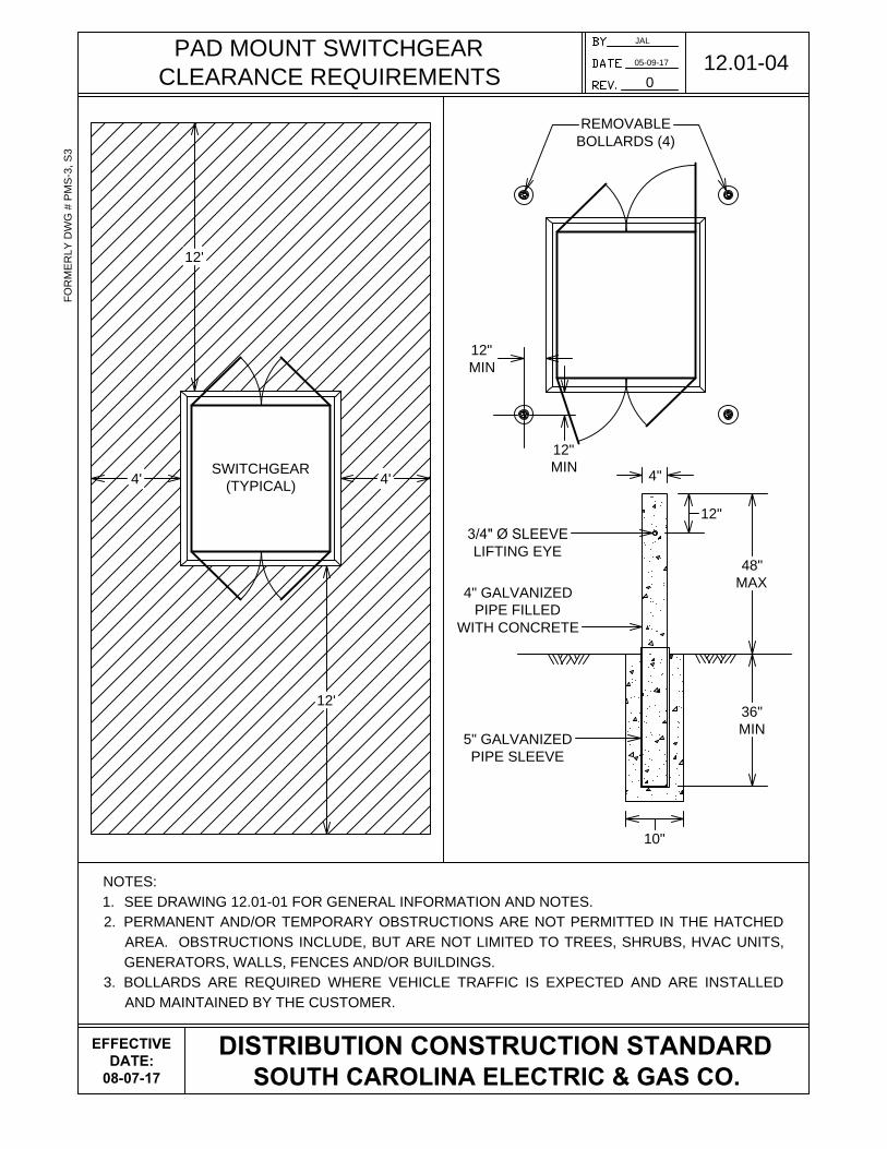
PAD MOUNT SWITCHGEAR
CLEARANCE REQUIREMENTS
NOTES:
1. SEE DRAWING 12.01-01 FOR GENERAL INFORMATION AND NOTES.
2. PERMANENT AND/OR TEMPORARY OBSTRUCTIONS ARE NOT PERMITTED IN THE HATCHED
AREA. OBSTRUCTIONS INCLUDE, BUT ARE NOT LIMITED TO TREES, SHRUBS, HVAC UNITS,
GENERATORS, WALLS, FENCES AND/OR BUILDINGS.
3. BOLLARDS ARE REQUIRED WHERE VEHICLE TRAFFIC IS EXPECTED AND ARE INSTALLED
AND MAINTAINED BY THE CUSTOMER.
JAL
05-09-17
0
12.01-04F
OR
ME
RLY
D
WG
# P
MS
-3, S
3
DISTRIBUTION CONSTRUCTION STANDARD
SOUTH CAROLINA ELECTRIC & GAS CO.
SWITCHGEAR
(TYPICAL)
4'4'
12'
12'
48"
MAX
36"
MIN
3/4" Ø SLEEVE
LIFTING EYE
4"
REMOVABLE
BOLLARDS (4)
12"
5" GALVANIZED
PIPE SLEEVE
10"
12"
MIN
12"
MIN
4" GALVANIZED
PIPE FILLED
WITH CONCRETE
EFFECTIVE
DATE:
08-07-17

TWO-HOLE NEMA LUGS FOR USE IN
THREE-PHASE PAD MOUNT TRANSFORMERS
JAL
01-10-18
1
14.02-03A
TWO-HOLE NEMA LUGS FOR STRANDED/COMPRESSED ALUMINUM
CABLE
SIZE
ANDERSON
CAT #
KEARNEY
DIE SIZE
ASK
CAT #
KEARNEY
DIE SIZE
BLACKBURN
CAT #
KEARNEY
DIE SIZE
1/0 STR VAUL1012BN 5/8 ALM1012/1.75TP 5/8 ALS6P 840
2/0 STR VAUL2012BN 840 ALM2012/1.75TP 840 ALS8P 840
3/0 STR VAUL3012BN 840 ALM3012/1.75TP 840 ALS10P 840
4/0 STR VAUL4012BN 840 ALM4012/1.75TP 840 ALS12P 840
250 KCM VAUL25012BN 29/32 ALM25012/1.75TP 840 ALS14P 1 1/8-1
300 KCM VAUL30012BN 29/32 ALM30012/1.75TP 1 1/8 ALS16P 1 1/8-1
350 KCM VAUL35012BN 29/32 ALM35012/1.75TP 1 1/8 ALS18P 1 1/8-1
400 KCM VAUL40012BN 1 1/8 ALM40012/1.75TP 1 5/16 ALS20P 1 1/8-1
500 KCM VAUL50012BN 1 1/8 ALM50012/1.75TP 1 5/16 ALS24P 1 5/16
600 KCM VAUL60012BN 1 5/16 ALM60012/1.75TP 1 5/16 ALS32P 1 5/16
700 KCM VAUL75012BN 1 5/16 AL70012/1.75TP 1 5/16 - -
750 KCM VAUL75012BN 1 5/16 AL75012/1.75TP 1 1/2 ALS44P 1 1/2
DISTRIBUTION CONSTRUCTION STANDARD
SOUTH CAROLINA ELECTRIC & GAS CO.
CABLE
SIZE
BURNDY
CAT #
KEARNEY
DIE SIZE
HOMAC
CAT #
KEARNEY
DIE SIZE
ILSCO
CAT #
KEARNEY
DIE SIZE
1/0 STR YA25A7 5/8 AL 1/0 NTN 5/8 ALND-1/0-12-134 5/8
2/0 STR YA26A3 5/8-1 AL 2/0 NTN 5/8-1 ALND-2/0-12-134 5/8-1
3/0 STR YA27A5 635 HEX AL 3/0 NTN 737 ALND-3/0-12-134 5/8-1
4/0 STR YA28A5 840 AL 4/0 NTN 840 ALND-4/0-12-134 840
250 KCM YA29A3 840 AL 250 NTN 840 ALND-250-12-134 840
300 KCM YA30A3 1 1/8-1 AL 300 NTN 1-2 ALND-300-12-134 1 5/8-2
350 KCM YA31A3 1 1/8-1 AL 350 NTN 1 1/8-1 ALND-350-12-134 1 5/8-2
400 KCM YA32A3 1 1/8-1 OR 2 AL 400 NTN 1 1/8-1 ALND-400-12-134 1 5/8-2
500 KCM YA34A3 1 1/8-1 OR 2 AL 500 NTN 1 5/16 - -
600 KCM YA36A3 1 5/16 AL 600 NTN 1 5/16 - -
700 KCM YA39A5 1 1/2 - - - -
750 KCM YA39A5 1 1/2 AL 750 NTN 1 1/2 - -
CABLE
SIZE
NSI
CAT #
KEARNEY
DIE SIZE
PANDUIT
CAT #
KEARNEY
DIE SIZE
PENN-UNION
CAT #
KEARNEY
DIE SIZE
1/0 STR AL1/0N 5/8 - - BLUA-1/0D3 5/8
2/0 STR AL2/0N 5/8-1 LAB2/0-12-5 5/8-1 BLUA-2/0D 5/8-1
3/0 STR AL3/0N 781 - - BLUA-3/0D 5/8-1
4/0 STR AL4/0N 840 LAB4/0-12-5 840 BLUA-4/0D 840
250 KCM AL250N 840 LAB250-12-5 840 BLUA-025D 840
300 KCM AL300N 1-2 LAB300-12-2 1-2 BLUA-030D 1-2
350 KCM AL350N 1 1/8-1 OR 2 LAB350-12-2 1 1/8-1 OR 2 BLUA-035D 1-2
400 KCM AL400N 1 1/8-1 OR 2 LAB400-12-2 1 1/8-1 OR 2 BLUA-040D2 1 1/8-2
500 KCM AL500NG 1 5/16 LAB500-12-2 1 5/16 - -
600 KCM AL600NG 1 5/16 LAB600-12-2 1 5/16 - -
700 KCM - - - - - -
750 KCM AL750NG 1 1/2 LAB750-12-1 1 1/2 - -
EFFECTIVE
DATE:
02-15-18
RE
V. 1
(01/10/18) - C
OR
RE
CT
ED
D
IE
S
IZ
E F
OR
B
UR
ND
Y Y
A39A
5
JAL
01-10-18
1
14.02-03B
DISTRIBUTION CONSTRUCTION STANDARD
SOUTH CAROLINA ELECTRIC & GAS CO.
TWO-HOLE NEMA LUGS FOR USE IN
THREE-PHASE PAD MOUNT TRANSFORMERS
TWO-HOLE NEMA LUGS FOR COMPACT ALUMINUM
CABLE
SIZE
ANDERSON
CAT #
KEARNEY
DIE SIZE
ASK
CAT #
KEARNEY
DIE SIZE
BLACKBURN
CAT #
KEARNEY
DIE SIZE
1/0 STR VAULH1012BN 840 ALM112/1.75TP 5/8 - -
2/0 STR VAULH1012BN 840 ALM1012/1.75TP 5/8 ALS6P 840
3/0 STR VAUL2012BN 840 ALM2012/1.75TP 840 ALS8P 840
4/0 STR VAUL3012BN 840 ALM3012/1.75TP 840 ALS10P 840
250 KCM VAUL40012BN 840 ALM4012/1.75TP 840 ALS14P 1 1/8-1
300 KCM VAUL25012BN 29/32 ALM25012/1.75TP 840 ALS14P 1 1/8-1
350 KCM VAUL30012BN 29/32 ALM30012/1.75TP 1 1/8 ALS16P 1 1/8-1
400 KCM VAUL35012BN 29/32 ALM35012/1.75TP 1 1/8 ALS18P 1 1/8-1
500 KCM VAUL40012BN 1 1/8 ALM40012/1.75TP 1 5/16 ALS20P 1 1/8-1
600 KCM VAUL50012BN 1 1/8 ALM50012/1.75TP 1 5/16 ALS24P 1 5/16
700 KCM VAUL60012BN 1 5/16 ALM60012/1.75TP 1 5/16 ALS28P 1 5/16
750 KCM VAUL75012BN 1 5/16 AL75012/1.75TP 1 1/2 ALS32P 1 5/16
CABLE
SIZE
BURNDY
CAT #
KEARNEY
DIE SIZE
HOMAC
CAT #
KEARNEY
DIE SIZE
ILSCO
CAT #
KEARNEY
DIE SIZE
1/0 STR YA25A7 5/8 SA 386NTN 5/8 ALND-1/0-12-134 5/8
2/0 STR YA26A3 5/8-1 AL 1/0 NTN 5/8 ALND-2/0-12-134 5/8-1
3/0 STR YA27A5 635 HEX AL 2/0 NTN 840 ALND-3/0-12-134 5/8-1
4/0 STR YA28A5 840 AL 3/0 NTN 840 ALND-4/0-12-134 840
250 KCM YA29A3 840 AL 4/0 NTN 840 ALND-250-12-134 840
300 KCM YA30A3 1 1/8-1 AL 4/0 NTN 840 ALND-300-12-134 1 5/8-2
350 KCM YA31A3 1 1/8-1 AL 300 NTN 1 1/8-1 ALND-350-12-134 1 5/8-2
400 KCM YA32A3 1 1/8-1 OR 2 AL 350 NTN 1 1/8-1 ALND-400-12-134 1 5/8-2
500 KCM YA34A3 1 1/8-1 OR 2 AL 400 NTN 1 5/16 - -
600 KCM YA36A3 1 5/16 AL 600 NTN 1 5/16 - -
700 KCM YA39A5 1 1/2 - - - -
750 KCM YA39A5 1 1/2 AL 750 NTN 1 1/2 - -
CABLE
SIZE
NSI
CAT #
KEARNEY
DIE SIZE
PANDUIT
CAT #
KEARNEY
DIE SIZE
PENN-UNION
CAT #
KEARNEY
DIE SIZE
1/0 STR AL1/0N 5/8 - - BLUA-1/0D3 5/8
2/0 STR AL2/0N 5/8-1 LAB2/0-12-5 5/8-1 BLUA-2/0D 5/8-1
3/0 STR AL3/0N 781 - - BLUA-3/0D 5/8-1
4/0 STR AL4/0N 840 LAB4/0-12-5 840 BLUA-4/0D 840
250 KCM AL250N 840 LAB250-12-5 840 BLUA-025D 840
300 KCM AL300N 1-2 LAB300-12-2 1-2 BLUA-030D 1-2
350 KCM AL350N 1 1/8-1 OR 2 LAB350-12-2 1 1/8-1 OR 2 BLUA-035D 1-2
400 KCM AL400N 1 1/8-1 OR 2 LAB400-12-2 1 1/8-1 OR 2 BLUA-040D2 1 1/8-2
500 KCM AL500NG 1 5/16 LAB500-12-2 1 5/16 - -
600 KCM AL600NG 1 5/16 LAB600-12-2 1 5/16 - -
700 KCM - - - - - -
750 KCM AL750NG 1 1/2 LAB750-12-1 1 1/2 - -
EFFECTIVE
DATE:
02-15-18
RE
V. 1
(01/10/18) - C
OR
RE
CT
ED
D
IE
S
IZ
E F
OR
B
UR
ND
Y Y
A39A
5

JAL
05-30-17
0
14.02-03C
DISTRIBUTION CONSTRUCTION STANDARD
SOUTH CAROLINA ELECTRIC & GAS CO.
TWO-HOLE NEMA LUGS FOR USE IN
THREE-PHASE PAD MOUNT TRANSFORMERS
FO
RM
ER
LY
D
WG
# C
AA
-6, S
2
TWO-HOLE NEMA LUGS FOR STRANDED/COMPRESSED COPPER
CABLE
SIZE
ANDERSON
CAT #
KEARNEY
DIE SIZE
ASK
CAT #
KEARNEY
DIE SIZE
BLACKBURN
CAT #
KEARNEY
DIE SIZE
1/0 STR CHL10BN 1/2 ELL1012/1.75XSH 1/2 LCN10 1/2
2/0 STR CHL20BN 9/16 ELL2012/1.75XSH 9/16 LCN20 9/16
3/0 STR CHL30BN 9/16 ELL3012/1.75XSH 5/8 LCN30 9/16
4/0 STR CHL40BN 5/8-1 ELL4012/1.75XSH 5/8-1 LCN40 5/8-1
250 KCM CHL250BN 11/16 ELL25012/1.75XSH 11/16 LCN250 11/16
300 KCM CHL300BN 781 ELL30012/1.75XSH 781 LCN300 781
350 KCM CHL350BN 840 ELL35012/1.75XSH 840 LCN350 840
400 KCM CHL400BN 15/16 ELL40012/1.75XSH 15/16 LCN400 15/16
500 KCM CHL500BN 1-2 ELL50012/1.75XSH 1-2 LCN500 1-2
600 KCM CHL600BN 1 1/8 ELL60012/1.75XSH 1 1/8-2 LCN600 1 1/8-2
700 KCM CHL750BNTT 1 5/16 ELL70012/1.75XSH 1 5/16 - -
750 KCM CHL750BNTT 1 5/16 ELL75012/1.75XSH 1 5/16 - -
CABLE
SIZE
BURNDY
CAT #
KEARNEY
DIE SIZE
HOMAC
CAT #
KEARNEY
DIE SIZE
ILSCO
CAT #
KEARNEY
DIE SIZE
1/0 STR YA252N 1/2 L 1/0 N 1/2 CLND-1/0-12-134 1/2
2/0 STR YA262N 9/16 L 2/0 N 9/16 CLND-2/0-12-134 9/16
3/0 STR YA272N 5/8-1 L 3/0 N 5/8 CLND-3/0-12-134 9/16
4/0 STR YA282N 5/8-1 L 4/0 N 5/8-1 CLND-4/0-12-134 5/8-1
250 KCM YA292N 737 L 250 N 11/16 CLND-250-12-134 11/16
300 KCM YA302N 737 OR 781 L 300 N 781 CLND-300-12-134 781
350 KCM YA312N 840 L 350 N 840 - -
400 KCM YA322N 840 L 400 N 15/16 CLND-400-12-134 840
500 KCM YA342N 1-2 L 500 N 1-2 CLND-500-12-134 1-2
600 KCM YA362N 1 1/8-2 L 600 N 1 1/8-2 CLND-600-12-134 1 1/8-2
700 KCM - - - - - -
750 KCM - - L 750 N 1 5/16 - -
CABLE
SIZE
NSI
CAT #
KEARNEY
DIE SIZE
PANDUIT
CAT #
KEARNEY
DIE SIZE
PENN-UNION
CAT #
KEARNEY
DIE SIZE
1/0 STR L10N 1/2 LCC1/0-12-X 1/2 BBLU-1/0D3 1/2
2/0 STR L20N 9/16 LCC2/0-12-X 9/16 BBLU-2/0D 9/16
3/0 STR L30N 5/8 LCC3/0-12-X 5/8 BBLU-3/0D 9/16
4/0 STR L40N 5/8-1 LCC4/0-12-X 5/8-1 BBLU-4/0D 5/8-1
250 KCM L250N 11/16 LCC250-12-X 11/16 BBLU-025D 11/16
300 KCM L300N 781 LCC300-12-X 781 BBLU-030D 781
350 KCM L350N 840 LCC350-12-X 840 BBLU-035D 840
400 KCM L400N 15/16 LCC400-12-6 15/16 BBLU-040D 15/16
500 KCM L500N 1-2 LCC500-12-6 1-2 BBLU-050D 1
600 KCM L600N 1 1/8-2 LCC600-12-6 1 1/8-2 BBLU-060D 1 1/8-2
700 KCM - - - - - -
750 KCM L750NG 1 5/16 LCC750-12-6 1 5/16 - -
EFFECTIVE
DATE:
08-07-17

JAL
06-09-17
0
16.01-04F
OR
ME
RLY
D
WG
# T
-1, S
5
DISTRIBUTION CONSTRUCTION STANDARD
SOUTH CAROLINA ELECTRIC & GAS CO.
12"
18"
42"
SOIL BACKFILL
CLEAN DIRT OR SAND
GAS
SECONDARY CABLE
PRIMARY CABLE
6"
WARNING TAPE
TRACER WIRE
30"
COMMUNICATION
CABLE
48"
18"
℄
JOINT USE WITH COMMUNICATION AND GAS AT
TRANSFORMER LOCATIONS TRENCHING DETAIL
NOTES:
1. ALL DIMENSIONS ARE MINIMUMS.
2. THE BOTTOM OF THE TRENCH SHALL BE UNDISTURBED, TAMPED, OR RELATIVELY SMOOTH
EARTH. WHERE THE EXCAVATION IS IN ROCK, THE CONDUIT/CABLE SHALL BE LAID ON A
PROTECTIVE LAYER OF CLEAN WELL-TAMPED BACKFILL.
3. BACKFILL WITHIN SIX INCHES OF THE CONDUIT/CABLE SHALL BE FREE OF MATERIAL WITH
SHARP EDGES. BACKFILL SHALL BE ADEQUATELY COMPACTED (MACHINE COMPACTION
SHALL NOT BE USED WITHIN SIX INCHES OF THE CABLE/CONDUIT).
TRANSFORMER
EFFECTIVE
DATE:
08-07-17
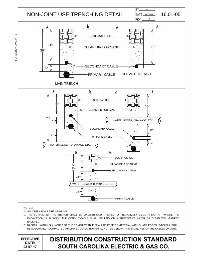
NON-JOINT USE TRENCHING DETAIL
JAL
06-09-17
0
16.01-05
FO
RM
ER
LY
D
WG
# T
-2
DISTRIBUTION CONSTRUCTION STANDARD
SOUTH CAROLINA ELECTRIC & GAS CO.
6"
30"
36"
30"
MAIN TRENCH
SERVICE TRENCH
SOIL BACKFILL
CLEAN DIRT OR SAND
SECONDARY CABLE
PRIMARY CABLE
NOTES:
1. ALL DIMENSIONS ARE MINIMUMS.
2. THE BOTTOM OF THE TRENCH SHALL BE UNDISTURBED, TAMPED, OR RELATIVELY SMOOTH EARTH. WHERE THE
EXCAVATION IS IN ROCK, THE CONDUIT/CABLE SHALL BE LAID ON A PROTECTIVE LAYER OF CLEAN WELL-TAMPED
BACKFILL.
3. BACKFILL WITHIN SIX INCHES OF THE CONDUIT/CABLE SHALL BE FREE OF MATERIAL WITH SHARP EDGES. BACKFILL SHALL
BE ADEQUATELY COMPACTED (MACHINE COMPACTION SHALL NOT BE USED WITHIN SIX INCHES OF THE CABLE/CONDUIT).
30"
>48"
SOIL BACKFILL
CLEAN DIRT OR SAND
SECONDARY CABLE
PRIMARY CABLE
WATER, SEWER, DRAINAGE, ETC.
6"
<42"
WATER, SEWER, DRAINAGE, ETC.
12"
30"
42"
TO
48"
WATER, SEWER, DRAINAGE, ETC.
SECONDARY CABLE
PRIMARY CABLE
SOIL BACKFILL
CLEAN DIRT OR SAND
12"
12"
12"
6"
EFFECTIVE
DATE:
08-07-17

ROAD CROSSING DETAIL
NOTES:
1. ALL DIMENSIONS ARE MINIMUMS.
2. GRAY SCHEDULE 40 ELECTRICAL CONDUIT IS REQUIRED FOR ALL ROAD AND PARKING LOT CROSSINGS. CONDUIT
SHALL BE CONTINUOUS WITH GLUED JOINTS, PULL STRING INSTALLED, AND CAPPED AT EACH END. CAPPED END
LOCATIONS TO BE IDENTIFIED BY A RED PVC MARKER, I.E., CONDUIT STUB PAINTED RED.
3. CONDUIT MUST TERMINATE WITHIN THE SCE&G ELECTRIC EASEMENT OF THE PROPERTY LOT (TERMINIATING IN
ROAD RIGHT-OF-WAY IS UNACCEPTABLE).
4. SEE DRAWING 16.01-02 FOR VERTICAL CLEARANCES.
JAL
06-12-17
0
16.01-06
FO
RM
ER
LY
D
WG
# T
-5
DISTRIBUTION CONSTRUCTION STANDARD
SOUTH CAROLINA ELECTRIC & GAS CO.
CROSSING
R/W
SECONDARY CONDUIT
PRIMARY CONDUIT
R/W
PVC MARKER
30"
36"
LOT 47
P
LP
L
P
L
P
L
P
L
P
L
ROAD
(50' R/W)
ROAD (50' R/W)
36"
SOIL BACKFILL
CLEAN DIRT OR SAND
PRIMARY CABLE
8'
WATER, SEWER,
DRAINAGE, ETC.
PARALLEL CLEARANCE
ROAD CROSSINGS
PVC MARKER
30"
36"
LOT 46
LOT 50
LOT 49
LOT 48
EFFECTIVE
DATE:
08-07-17
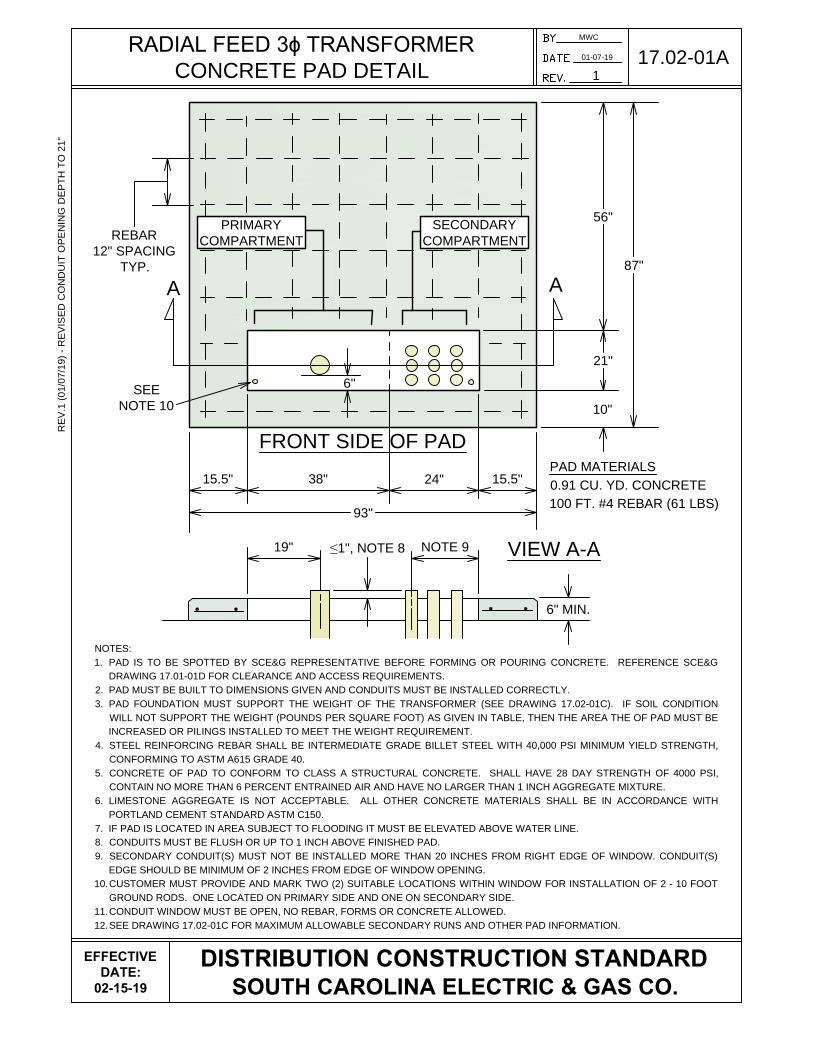
RADIAL FEED 3ɸ TRANSFORMER
CONCRETE PAD DETAIL
MWC
01-07-19
1
17.02-01AR
EV
.1 (01/07/19) - R
EV
IS
ED
C
ON
DU
IT
O
PE
NIN
G D
EP
TH
T
O 21"
DISTRIBUTION CONSTRUCTION STANDARD
SOUTH CAROLINA ELECTRIC & GAS CO.
EFFECTIVE
DATE:
02-15-19
15.5"
A
A
6"
FRONT SIDE OF PAD
SECONDARY
COMPARTMENT
PRIMARY
COMPARTMENT
87"
56"
21"
10"
93"
≤1", NOTE 8
6" MIN.
VIEW A-A
19" NOTE 9
SEE
NOTE 10
PAD MATERIALS
0.91 CU. YD. CONCRETE
100 FT. #4 REBAR (61 LBS)
NOTES:
1. PAD IS TO BE SPOTTED BY SCE&G REPRESENTATIVE BEFORE FORMING OR POURING CONCRETE. REFERENCE SCE&G
DRAWING 17.01-01D FOR CLEARANCE AND ACCESS REQUIREMENTS.
2. PAD MUST BE BUILT TO DIMENSIONS GIVEN AND CONDUITS MUST BE INSTALLED CORRECTLY.
3. PAD FOUNDATION MUST SUPPORT THE WEIGHT OF THE TRANSFORMER (SEE DRAWING 17.02-01C). IF SOIL CONDITION
WILL NOT SUPPORT THE WEIGHT (POUNDS PER SQUARE FOOT) AS GIVEN IN TABLE, THEN THE AREA THE OF PAD MUST BE
INCREASED OR PILINGS INSTALLED TO MEET THE WEIGHT REQUIREMENT.
4. STEEL REINFORCING REBAR SHALL BE INTERMEDIATE GRADE BILLET STEEL WITH 40,000 PSI MINIMUM YIELD STRENGTH,
CONFORMING TO ASTM A615 GRADE 40.
5. CONCRETE OF PAD TO CONFORM TO CLASS A STRUCTURAL CONCRETE. SHALL HAVE 28 DAY STRENGTH OF 4000 PSI,
CONTAIN NO MORE THAN 6 PERCENT ENTRAINED AIR AND HAVE NO LARGER THAN 1 INCH AGGREGATE MIXTURE.
6. LIMESTONE AGGREGATE IS NOT ACCEPTABLE. ALL OTHER CONCRETE MATERIALS SHALL BE IN ACCORDANCE WITH
PORTLAND CEMENT STANDARD ASTM C150.
7. IF PAD IS LOCATED IN AREA SUBJECT TO FLOODING IT MUST BE ELEVATED ABOVE WATER LINE.
8. CONDUITS MUST BE FLUSH OR UP TO 1 INCH ABOVE FINISHED PAD.
9. SECONDARY CONDUIT(S) MUST NOT BE INSTALLED MORE THAN 20 INCHES FROM RIGHT EDGE OF WINDOW. CONDUIT(S)
EDGE SHOULD BE MINIMUM OF 2 INCHES FROM EDGE OF WINDOW OPENING.
10.CUSTOMER MUST PROVIDE AND MARK TWO (2) SUITABLE LOCATIONS WITHIN WINDOW FOR INSTALLATION OF 2 - 10 FOOT
GROUND RODS. ONE LOCATED ON PRIMARY SIDE AND ONE ON SECONDARY SIDE.
11.CONDUIT WINDOW MUST BE OPEN, NO REBAR, FORMS OR CONCRETE ALLOWED.
12.SEE DRAWING 17.02-01C FOR MAXIMUM ALLOWABLE SECONDARY RUNS AND OTHER PAD INFORMATION.
REBAR
12" SPACING
TYP.
38" 24" 15.5"

LOOP FEED 3ɸ TRANSFORMER
CONCRETE PAD DETAIL
MWC
01-07-19
1
17.02-01BR
EV
.1 (01/07/19) - R
EV
IS
ED
C
ON
DU
IT
O
PE
NIN
G D
EP
TH
T
O 21"
DISTRIBUTION CONSTRUCTION STANDARD
SOUTH CAROLINA ELECTRIC & GAS CO.
EFFECTIVE
DATE:
02-15-19
A
A
24" 37" 25" 24"
110"
9"
18" NOTE 9
6"
6" MIN.
70"
21"
10"
101"
VIEW A-A
REBAR
12" SPACING
TYP.
SEE
NOTE 10
PAD MATERIALS
1.3 CU. YD. CONCRETE
150 FT. #4 REBAR (88 LBS)
SECONDARY
COMPARTMENT
PRIMARY
COMPARTMENT
NOTES:
1. PAD IS TO BE SPOTTED BY SCE&G REPRESENTATIVE BEFORE FORMING OR POURING CONCRETE. REFERENCE SCE&G DRAWING
17.01-01D FOR CLEARANCE AND ACCESS REQUIREMENTS.
2. PAD MUST BE BUILT TO DIMENSIONS GIVEN AND CONDUITS MUST BE INSTALLED CORRECTLY.
3. PAD FOUNDATION MUST SUPPORT THE WEIGHT OF THE TRANSFORMER (SEE DRAWING 17.02-01C). IF SOIL CONDITION WILL NOT
SUPPORT THE WEIGHT (POUNDS PER SQUARE FOOT) AS GIVEN IN TABLE, THEN THE AREA THE OF PAD MUST BE INCREASED OR
PILINGS INSTALLED TO MEET THE WEIGHT REQUIREMENT.
4. STEEL REINFORCING REBAR SHALL BE INTERMEDIATE GRADE BILLET STEEL WITH 40,000 PSI MINIMUM YIELD STRENGTH,
CONFORMING TO ASTM A615 GRADE 40.
5. CONCRETE OF PAD TO CONFORM TO CLASS A STRUCTURAL CONCRETE. SHALL HAVE 28 DAY STRENGTH OF 4000 PSI, CONTAIN NO
MORE THAN 6 PERCENT ENTRAINED AIR AND HAVE NO LARGER THAN 1 INCH AGGREGATE MIXTURE.
6. LIMESTONE AGGREGATE IS NOT ACCEPTABLE. ALL OTHER CONCRETE MATERIALS SHALL BE IN ACCORDANCE WITH PORTLAND
CEMENT STANDARD ASTM C150.
7. IF PAD IS LOCATED IN AREA SUBJECT TO FLOODING IT MUST BE ELEVATED ABOVE WATER LINE.
8. CONDUITS MUST BE FLUSH OR UP TO 1 INCH ABOVE FINISHED PAD.
9. SECONDARY CONDUIT(S) MUST NOT BE INSTALLED MORE THAN 20 INCHES FROM RIGHT EDGE OF WINDOW. CONDUIT(S) EDGE
SHOULD BE MINIMUM OF 2 INCHES FROM EDGE OF WINDOW OPENING.
10.CUSTOMER MUST PROVIDE AND MARK TWO (2) SUITABLE LOCATIONS WITHIN WINDOW FOR INSTALLATION OF 2 - 10 FOOT GROUND
RODS. ONE LOCATED ON PRIMARY SIDE AND ONE ON SECONDARY SIDE.
11.CONDUIT WINDOW MUST BE OPEN, NO REBAR, FORMS OR CONCRETE ALLOWED.
12.SEE DRAWING 17.02-01C FOR MAXIMUM ALLOWABLE SECONDARY RUNS AND OTHER PAD INFORMATION.
FRONT SIDE OF PAD
≤1"
NOTE 8
LOOP IN LOOP OUT

3ɸ TRANSFORMER CONCRETE PAD
SUPPLEMENTAL DETAILS
MWC
01-07-19
1
17.02-01CR
EV
.1 (01/07/19) - IN
CR
EA
SE
D C
ON
DU
CT
OR
S P
ER
P
HA
SE
DISTRIBUTION CONSTRUCTION STANDARD
SOUTH CAROLINA ELECTRIC & GAS CO.
EFFECTIVE
DATE:
02-15-19
TRANSFORMER PROPERTIES
TRANSFORMER
KVA
MAXIMUM CONDUCTORS
PER PHASE APPROXIMATE
WEIGHT (LBS)
APPROXIMATE
LBS/FT^2
VOLTAGE
120 / 208 Y
VOLTAGE
277 / 480 Y
150 16 144,000
150
225 16 144,500
150
300 16 145,000
300
500 16 146,000
300
750 16 1410,000
400
1000 - 1410,000
400
1500 - 1412,000
500
2000 - 1614,500
500
2500 - 1815,000
500
NOTES:
1. PAD MUST BE DIMENSIONALLY CORRECT, INCLUDING LOCATION OF CONDUITS. FAILURE
TO DO SO CAN DELAY SERVICE AND REQUIRE CORRECTIVE ACTION BY THE CUSTOMER.
2. ALLOWABLE NUMBER OF SECONDARY RUNS IS LIMITED BY TRANSFORMER KVA SIZE.
3. SECONDARY CONDUCTOR IS ALLOWED ONLY IN SECONDARY COMPARTMENT.
4. LIMIT CUSTOMER CONDUCTORS PER PHASE TO ENSURE THAT SPACE IS AVAILABLE FOR
LIGHTING AND CT METERING WHEN APPLICABLE.

GUIDE FOR LOCATING/SPOTTING
3ɸ PAD-MOUNTED TRANSFORMER
MWC
07-07-17
0
17.02-01D
FO
RM
ER
LY
D
WG
# T
UG
-1 S
H 4
DISTRIBUTION CONSTRUCTION STANDARD
SOUTH CAROLINA ELECTRIC & GAS CO.
EFFECTIVE
DATE:
08-07-17
TOP VIEW
X X X X
FENCE
PR
OP
ER
TY
LIN
E
BU
ILD
IN
G, B
RIC
K W
ALL, E
TC
.
4' - 0" MIN.
4' - 0" MIN. 4' - 0" MIN.
CONCRETE
PAD
SS
S
8' - 0" MIN
(TYPICAL ALL SIDES)
FENCE, BUILDING OR ANY
ABOVE GRADE OBSTRUCTION
12' - 0" MIN.
FROM DOOR SIDE
ANY UG UTILITY
I.E. WATER, SEWER, DRAINAGE, ETC.
REMOVABLE
BOLLARD
(TYPICAL)
METER
PAD WINDOW
NOTES:
1. PAD LOCATION AND ORIENTATION (DOORS/WINDOWS) MUST BE SPOTTED BY SCE&G REPRESENTATIVE. APPROVAL OF SITE
BEFORE POURING CONCRETE IS RECOMMENDED. UNACCEPTABLE CONSTRUCTION WILL BE REJECTED AND CORRECTION
REQUIRED BEFORE PLACEMENT OF SCE&G EQUIPMENT.
2. TRUCK ACCESS - 10 FEET MINIMUM CORRIDOR IS REQUIRED TO WITHIN 1 FOOT OF PAD FOUNDATION.
3. TRUCK WORK AREA - SETTING OR REMOVING TRANSFORMER REQUIRES KNUCKLE BOOM TRUCK AND TRAILER. THEREFORE 30'
X 18' CLEAR WORK AREA ADJACENT TO TRANSFORMER PAD IS REQUIRED.
4. OVERHANGING VERTICAL CLEARANCE OF 40 FEET IS REQUIRED ABOVE CONCRETE PAD.
5. MINIMUM SAFE WORKING ZONE OF 12 FEET IS REQUIRED FROM TRANSFORMER ACCESS DOOR. ONLY EXCEPTION IS EASILY
REMOVABLE FENCE/OBJECT.
6. IF ALL SIDES ARE SCREENED AN INSIDE VENTILATION AREA OF 625 SQUARE FEET (25' X 25') MINIMUM MUST BE PROVIDED.
7. FUEL STORAGE TANKS, FUEL DISPENSING POINTS, AND CUSTOMER OWNED GENERATORS MUST BE A MINIMUM OF 20 FEET
FROM THE PAD EDGE.
8. FLAMMABLE WALLS OR FENCING MUST BE MINIMUM OF 10 FEET FROM PAD EDGE.
9. NO UNDERGROUND UTILITIES UNDER OR WITHIN 8 FEET OF PAD (CONCRETE FOUNDATION).
10. MINIMUM "ABOVE GRADE" CLEARANCE ON ALL SIDES IS 4 FEET MINIMUM, EXCEPTION IS FRONT OR DOOR SIDE REQUIRING SAFE
WORKING ZONE OF 12 FEET.
11. REMOVABLE BOLLARDS ARE REQUIRED WHERE VEHICLE TRAFFIC IS EXPECTED. THESE DEVICES ARE TO PROTECT THE
PAD-MOUNTED GEAR FROM VEHICLE DAMAGE.
12. REMOVABLE BOLLARDS ARE PROVIDED, INSTALLED AND MAINTAINED BY THE CUSTOMER.
12"
12"
4' - 0" (MAX.)
3' - 0" (MIN.)
REMOVABLE BOLLARD
4" GALVANIZED PIPE
FILLED WITH CONCRETE
WITH 5" GALVANIZED PIPE SLEEVE
5" PIPE SLEEVE
12"
3/4" Ø SLEEVE
LIFTING EYE
4" 3"3"

METER CLEARANCE REQUIREMENTS
NOTES:
1. SEE DRAWING 19.01-01 FOR GENERAL INFORMATION AND NOTES.
2. PERMANENT AND/OR TEMPORARY OBSTRUCTIONS ARE NOT PERMITTED WITHIN THREE
FEET IN ANY DIRECTION OF AN ELECTRIC METER.
3. OBSTRUCTIONS INCLUDE, BUT ARE NOT LIMITED TO TREES, SHRUBS, HVAC UNITS,
GENERATORS, WALLS, FENCES, GAS METERS AND/OR BUILDINGS.
4. SEE DRAWING 19.01-05 FOR GANGED METER SOCKETS.
JAL
07-10-17
1
19.01-03
DISTRIBUTION CONSTRUCTION STANDARD
SOUTH CAROLINA ELECTRIC & GAS CO.
EFFECTIVE
DATE:
06-05-17
3' 3'
3'
6'-0" MAX
4'-6" MIN
3'
3' 3'
SEE NOTE 3
RE
V. 1 (07/10/17) - A
DD
ED
G
AS
M
ET
ER
S T
O N
OT
E 3
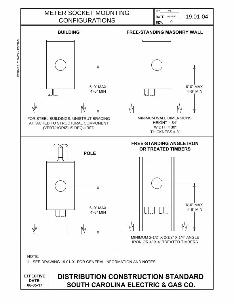
METER SOCKET MOUNTING
CONFIGURATIONS
NOTE:
1. SEE DRAWING 19.01-01 FOR GENERAL INFORMATION AND NOTES.
JAL
05-03-17
0
19.01-04
FO
RM
ER
LY
D
WG
# P
MT
R-5
DISTRIBUTION CONSTRUCTION STANDARD
SOUTH CAROLINA ELECTRIC & GAS CO.
BUILDING
FREE-STANDING ANGLE IRON
OR TREATED TIMBERS
FOR STEEL BUILDINGS, UNISTRUT BRACING
ATTACHED TO STRUCTURAL COMPONENT
(VERT/HORIZ) IS REQUIRED
6'-0" MAX
4'-6" MIN
MINIMUM 2-1/2" X 2-1/2" X 1/4" ANGLE
IRON OR 4" X 4" TREATED TIMBERS
6'-0" MAX
4'-6" MIN
POLE
FREE-STANDING MASONRY WALL
6'-0" MAX
4'-6" MIN
6'-0" MAX
4'-6" MIN
MINIMUM WALL DIMENSIONS:
HEIGHT = 84"
WIDTH = 30"
THICKNESS = 8"
EFFECTIVE
DATE:
06-05-17

MODULAR (GANGED) METER ASSEMBLY
NOTES:
1. SEE DRAWING 19.01-01 FOR GENERAL INFORMATION AND NOTES.
2. EACH METER SOCKET SHALL BE PLAINLY AND PERMANENTLY MARKED, I.E., STENCILED
WITH ENAMEL PAINT, WITH UNIT NUMBER OR OTHER DESCRIPTION ON THE INSIDE OF THE
METER SOCKET AND ON THE OUTSIDE OF THE METER SOCKET COVER.
3. SCE&G PERSONNEL SHALL VERIFY THE UNIT NUMBER OR OTHER DESCRIPTION MATCHES
WHAT IS STENCILED BEFORE SETTING A METER.
4. SCE&G CANNOT ATTACH TO MAIN BREAKER OR DISCONNECT DEVICE. IF INSTALLED,
CUSTOMER CONNECTION POINT WILL BE A HANDHOLE OR OTHER DESIGNATED LOCATION.
JAL
05-03-17
0
19.01-05
FO
RM
ER
LY
D
WG
# M
TR
-G
DISTRIBUTION CONSTRUCTION STANDARD
SOUTH CAROLINA ELECTRIC & GAS CO.
ON
OFF
FINISHED GRADE OR FLOOR
6'-0" MAX
3'-6" MIN
SEE NOTE 4
101
102
103 107
106
105
104
EFFECTIVE
DATE:
06-05-17


