Undersampled Phase Shift ON-OFF Keying for Camera Communication
Pengfei Luo1, Zabih Ghassemlooy1, Hoa Le Minh1, Xuan Tang2, Hsin-Mu Tsai3 1Optical Communications Research Group, NCRLab, Faculty of Engineering and Environment,
Northumbria University, Newcastle-upon-Tyne, United Kingdom Email: {oliver.luo, z.ghassemlooy, hoa.le-minh}@northumbria.ac.uk
2Department of Electronic Engineering, Tsinghua University, Beijing, China Email: [email protected]
3Department of Computer Science and Information Engineering, National Taiwan University, Taipei, Taiwan Email: [email protected]
Abstract—In this paper, an optical camera communication system utilizing the under-sampled phase shift ON-OFF keying modulation is proposed to support non-flickering visible light communication. This system sends three types of light symbols through light emitting diode (LED) lamps, which are recorded by a camera. By employing a dual LED lamp with a designated mapping and framing method, the data rate can reach up to 3 times of the camera’s frame rate. The experiment results show that the proposed camera communication system can achieve 150 bps error-free communications for a range up to 12 m.
Keywords—camera communications; phase shift keying; visible light communication
I. INTRODUCTION As a result of the major advances in solid-state lighting
technologies, we are seeing a rapid installation of high luminance light-emitting diode (LED) lighting fixtures at a global level in places such as homes, offices, shopping mall, transportations, traffic and street lights, and mobile phone (flash light). Compared to the traditional lighting fixtures, LEDs have an interesting feature such as higher energy efficiency and the ability to be switched on and off at fast rates [1]. Therefore, LEDs have been considered not only for illumination, but also for wireless data communications [2]. In indoor application such a technology can offer a noticeable spectrum relief for the wireless local area networks that uses the congested radio frequency spectrum. In indoor applications, the typical illumination level of > 400 lux is sufficient enough for data transmission at high signal-to-noise ratio (SNR) [3].
In optical wireless communications visible LEDs can be used for downlink as well as uplink communications [4]. Whereas photodiodes (PD) (PIN or an avalanche photodiode) are typically adopted as the receiver. Such systems have reasonably high bandwidth in the range of tens of megahertz (MHz) [5]. Higher data rates (i.e > 1 Gbps) can be achieved by employing high spectral efficiency modulation schemes including orthogonal frequency-division multiplexing (OFDM) [6], wavelength-division multiplexing (WDM) [7], spatial-division multiplexing (SDM) [8]. Alternatively higher data rates can be achieved by exploiting the spectral efficiency
of multiple LEDs commonly used to provide sufficient illumination. This is achieved by means of implementing optical multiple-input and multiple-output (MIMO) communication system [9], offer high data rate by increasing the spectral efficiency [10]. However, in indoor environments there are no fading and therefore, optical wireless links are envisaged to be highly correlated enabling only minor diversity gains with MIMO. Additionally signal collision due to multiple LEDs based link will lead to the interference that will ultimately degrade the system bit error rate (BER) performance [11].
In recent few years we have seen extensive use of smartphones, tablets, Google glasses etc. in our daily life. Such devices have built-in cameras, which can be used to capture images and videos, therefore, have potential to be utilized as visible light communications (VLC) receivers [9]. In [12] VLC system employing image sensor-based camera has been reported. This image sensor-based communication system or camera communication (CamCom) offers non-interference communication with SDM [13], which extracts different signal from different spatial position from the captured videos or photos. On the other hand, LEDs are being widely used for lighting in most modern vehicles and for traffics lights, which can be readily modified to act as VLC transmitters. Therefore, to develop intelligent transport systems (ITS), VLC can be used between the cars and the road side infrastructures by utilizing the vehicle lighting, traffic and street signals and smartphone cameras. Smartphone can be mounted in a car, motorbikes, and its camera can be used to capture the images of lights from the vehicles nearby.
For most commercial cameras, the frame rate is relatively low, typically 24 frames per second (fps), 30 fps 50 fps and 60 fps, which results in low data rate as if they were used as communication receivers [14]. However, such low speed data rates is sufficient for certain application scenarios, e.g. collision detection, information on hazardous road condition and capturing the vehicle’s diagnostic information via the vehicles’ taillights [15].
In [14] a CamCom scheme utilizing the rolling shutter effect of a complementary metal-oxide-semiconductor (CMOS) camera and Manchester coding was proposed to
2014 Sixth International Conference on Wireless Communications and Signal Processing (WCSP)
increase the data rate. However in this approach the whole CMOS sensor should be flooded with light, which greatly restricts the communication distance. Casio’s PicapiCamera uses smartphone screen or LED lamps to send a blinking signal from LEDs at different colours, which is then read by the camera on the other smartphone. This is realized through combination of location information and cloud service based on VLCs [16]. In [17] an under-sampled frequency shift ON-OFF keying (UFSOOK) modulation scheme with low data rate capabilities has been proposed with no bit flicker or frame flicker. With UFSOOK the camera can decodes video frames back to the data stream at a data rate of 15 bps using a 30 fps camera.
In this paper, an under-sampled phase shift ON-OFF keying (UPSOOK) modulation scheme is proposed, which is similar to the phase shift keying (PSK). We send the mark (logic 1) and space (logic 0) with the same frequency and amplitude but with the opposite phase carrier signals. At the receiver, the transmitted signal is under-sampled by a low frame rate camera, and the captured videos are then processed by the UPSOOK demodulation scheme. The proposed system can be used in VLC marketing similar to quick response (QR) code, or in car-to-car VLC system to exchange traffic information between nearby vehicles.
The rest of the paper is organized as follows. In Section II, we introduce the concept of the UPSOOK modulation, signal mapping, as well as framing method. An experimental setup to evaluate the system performance is described in Section III. Finally conclusions and future work are given in Section IV.
II. CAMERA COMMUNICATION
A. UPSOOK When recording a video, the camera captures continuous
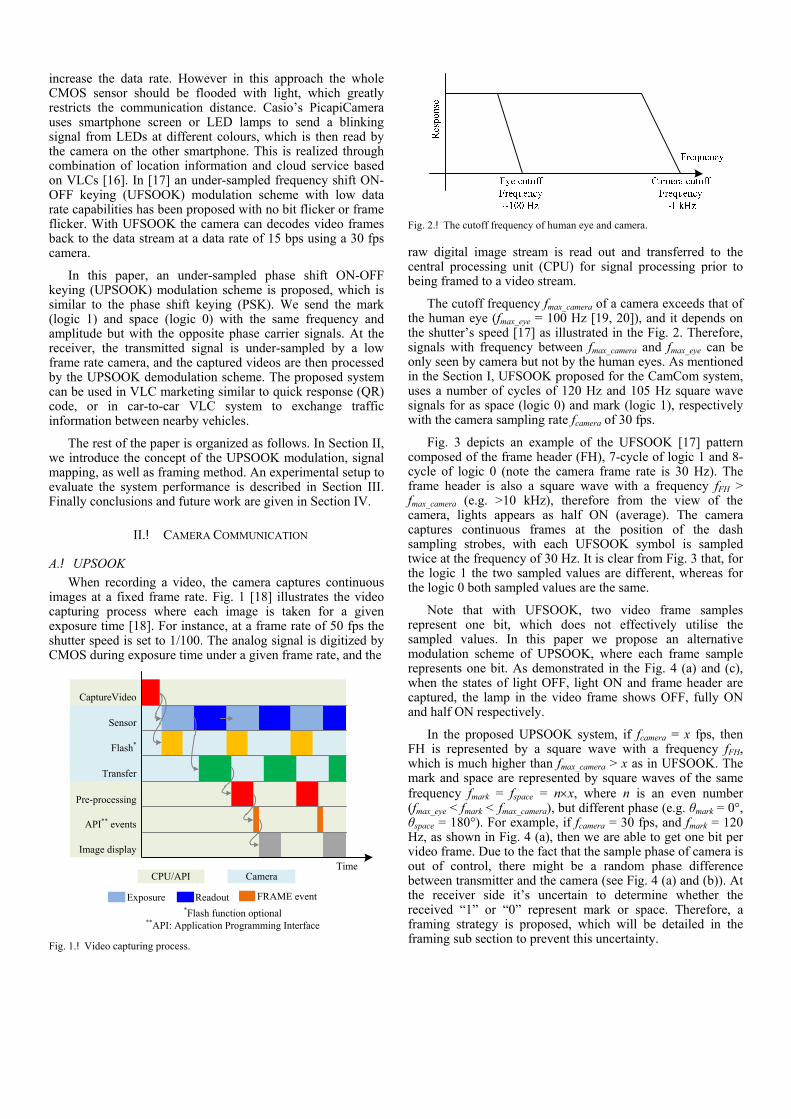
images at a fixed frame rate. Fig. 1 [18] illustrates the video capturing process where each image is taken for a given exposure time [18]. For instance, at a frame rate of 50 fps the shutter speed is set to 1/100. The analog signal is digitized by CMOS during exposure time under a given frame rate, and the
Fig. 1. Video capturing process.
Fig. 2. The cutoff frequency of human eye and camera.
raw digital image stream is read out and transferred to the central processing unit (CPU) for signal processing prior to being framed to a video stream.
The cutoff frequency fmax_camera of a camera exceeds that of the human eye (fmax_eye = 100 Hz [19, 20]), and it depends on the shutter’s speed [17] as illustrated in the Fig. 2. Therefore, signals with frequency between fmax_camera and fmax_eye can be only seen by camera but not by the human eyes. As mentioned in the Section I, UFSOOK proposed for the CamCom system, uses a number of cycles of 120 Hz and 105 Hz square wave signals for as space (logic 0) and mark (logic 1), respectively with the camera sampling rate fcamera of 30 fps.
Fig. 3 depicts an example of the UFSOOK [17] pattern composed of the frame header (FH), 7-cycle of logic 1 and 8-cycle of logic 0 (note the camera frame rate is 30 Hz). The frame header is also a square wave with a frequency fFH > fmax_camera (e.g. >10 kHz), therefore from the view of the camera, lights appears as half ON (average). The camera captures continuous frames at the position of the dash sampling strobes, with each UFSOOK symbol is sampled twice at the frequency of 30 Hz. It is clear from Fig. 3 that, for the logic 1 the two sampled values are different, whereas for the logic 0 both sampled values are the same.
Note that with UFSOOK, two video frame samples represent one bit, which does not effectively utilise the sampled values. In this paper we propose an alternative modulation scheme of UPSOOK, where each frame sample represents one bit. As demonstrated in the Fig. 4 (a) and (c), when the states of light OFF, light ON and frame header are captured, the lamp in the video frame shows OFF, fully ON and half ON respectively.
In the proposed UPSOOK system, if fcamera = x fps, then FH is represented by a square wave with a frequency fFH, which is much higher than fmax_camera > x as in UFSOOK. The mark and space are represented by square waves of the same frequency fmark = fspace = nux, where n is an even number (fmax_eye < fmark < fmax_camera), but different phase (e.g. θmark = 0°, θspace = 180°). For example, if fcamera = 30 fps, and fmark = 120 Hz, as shown in Fig. 4 (a), then we are able to get one bit per video frame. Due to the fact that the sample phase of camera is out of control, there might be a random phase difference between transmitter and the camera (see Fig. 4 (a) and (b)). At the receiver side it’s uncertain to determine whether the received “1” or “0” represent mark or space. Therefore, a framing strategy is proposed, which will be detailed in the framing sub section to prevent this uncertainty.
Time
FRAME eventExposure Readout
CPU/API Camera
*Flash function optional**API: Application Programming Interface
CaptureVideo
Sensor
Flash*
Transfer
Pre-processing
API** events
Image display
Fig. 3. An example of the UFSOOK pattern “FH,0,1” (fcamera = 30 fps, fFH = 25 kHz, fspace = 120 Hz, fmark = 105 Hz).
Fig. 4. An example of the UPSOOK patterns (fcamera = 30 fps, fFH = 10 kHz, fspace = fmark = 120 Hz, θmark = 0º, θspace = 180º): (a) and (b) are two sampeled resutles for the same transmited signal, and (c) demonstrates the three possible smapled results.
B. Mapping From Section I, it is clear that the captured light from the
LED lamp has three states: OFF, fully ON and half ON when adopting UFSOOK or UPSOOK. Therefore, for m LEDs > m-bit per video frame can be allocated if a signal mapping method is employed.
In this paper as a proof of concept we have used 2 LED lamps. Therefore, the captured lights have 9 states in total. Accordingly, a mapping method is proposed to maximize the use of frame efficiency, which is listed in the Table I. Each parallel output of index 0-7 in Table I carries 3-bit data per symbol, for instance, when the original data (0, 0, 0) is to be sent, after signal mapping two space symbols will be
TABLE I. SIGNAL MAPPING
Index Serial Input Parallel Output
0 0, 0, 0 SPACE, SPACE
1 0, 0, 1 SPACE, MARK
2 0, 1, 0 SPACE, FH
3 0, 1, 1 MARK, SPACE
4 1, 0, 0 MARK, MARK
5 1, 0, 1 MARK, FH
6 1, 1, 0 FH, SPACE
7 1, 1, 1 FH, MARK
8 - - - FH, FH
TABLE II. SIGNAL DEMAPPING
Index Parallel Input Serial Output
0 OFF, OFF 0, 0, 0
1 OFF, FULLY ON 0, 0, 1
2 OFF, HALF ON 0, 1, 0
3 FULLY ON, OFF 0, 1, 1
4 FULLY ON, FULLY ON 1, 0, 0
5 FULLY ON, HALF ON 1, 0, 1
6 HALF ON, OFF 1, 1, 0
7 HALF ON, FULLY ON 1, 1, 1
8 HALF ON, HALF ON - - -
transmitted through two LED lamps at the same time. While for index 8, it is used as the start frame of each data frame, which will be discussed in the next sub section.
Similarly, at the receiver side, when the camera captures two OFF states in one video frame, according to Table II, the demapped data should be (0, 0, 0). To make the mapping and demapping method work correctly, the phase different error — if it exists — should be corrected as has been discussed in the previous Section. So a frame strategy is proposed to achieve this function.
C. Framing Since we employ two LED lamps in this paper, the
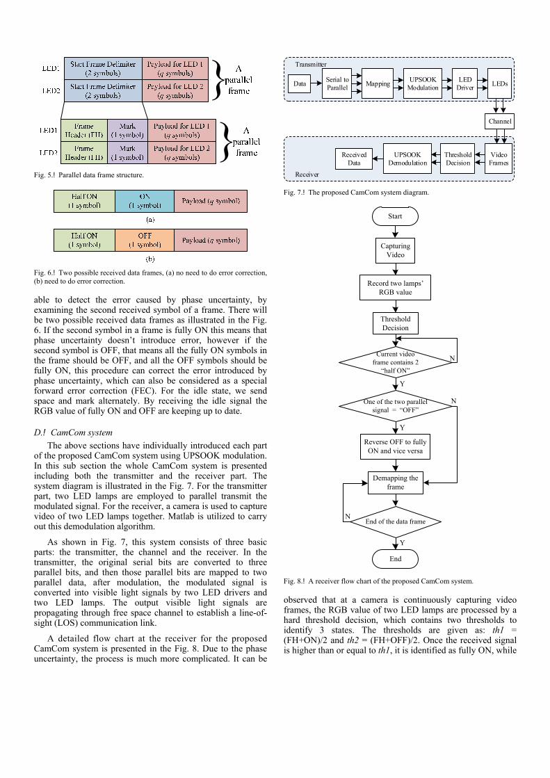
proposed data frame strategy is described as follows: each two q-mapped UPSOOK symbols are packed as the payload of a parallel data frame, and a start frame delimiter (SFD) is added at the beginning of each payload to enable asynchronous communication as shown in Fig. 5. For each SFD, it is composed of 2 symbols, the first symbol is the frame header, which is the square wave with a frequency of fFH and with a time duration of 1/fcamera. The second symbol of SFD is the mark symbol which is also a square wave with a frequency of fmark and a time duration of 1/fcamera. as shown in the first two symbols in Fig. 4 (a) and Fig. 5.
In Fig. 4 it may be seen that the phase uncertainty problem will only cause error when receiving a mark or a space signal, while it has no effect on frame header signal. Therefore, if we send data according to the proposed frame strategy, we are
Frame header Logic 1 Logic 0
Light ON
Light OFF
time
(b)0.5 0 0 1
Light ON
Light OFF
time
(a)
(c)0.50 1
0.5 1 1 0 time
Light ON
Light OFF
Fig. 5. Parallel data frame structure.
Fig. 6. Two possible received data frames, (a) no need to do error correction, (b) need to do error correction.
able to detect the error caused by phase uncertainty, by examining the second received symbol of a frame. There will be two possible received data frames as illustrated in the Fig. 6. If the second symbol in a frame is fully ON this means that phase uncertainty doesn’t introduce error, however if the second symbol is OFF, that means all the fully ON symbols in the frame should be OFF, and all the OFF symbols should be fully ON, this procedure can correct the error introduced by phase uncertainty, which can also be considered as a special forward error correction (FEC). For the idle state, we send space and mark alternately. By receiving the idle signal the RGB value of fully ON and OFF are keeping up to date.
D. CamCom system The above sections have individually introduced each part
of the proposed CamCom system using UPSOOK modulation. In this sub section the whole CamCom system is presented including both the transmitter and the receiver part. The system diagram is illustrated in the Fig. 7. For the transmitter part, two LED lamps are employed to parallel transmit the modulated signal. For the receiver, a camera is used to capture video of two LED lamps together. Matlab is utilized to carry out this demodulation algorithm.
As shown in Fig. 7, this system consists of three basic parts: the transmitter, the channel and the receiver. In the transmitter, the original serial bits are converted to three parallel bits, and then those parallel bits are mapped to two parallel data, after modulation, the modulated signal is converted into visible light signals by two LED drivers and two LED lamps. The output visible light signals are propagating through free space channel to establish a line-of-sight (LOS) communication link.
A detailed flow chart at the receiver for the proposed CamCom system is presented in the Fig. 8. Due to the phase uncertainty, the process is much more complicated. It can be
Fig. 7. The proposed CamCom system diagram.
Fig. 8. A receiver flow chart of the proposed CamCom system.
observed that at a camera is continuously capturing video frames, the RGB value of two LED lamps are processed by a hard threshold decision, which contains two thresholds to identify 3 states. The thresholds are given as: th1 = (FH+ON)/2 and th2 = (FH+OFF)/2. Once the received signal is higher than or equal to th1, it is identified as fully ON, while
Data Serial to Parallel Mapping UPSOOK
ModulationLED
Driver LEDs
Channel
VideoFrames
Threshold Decision
UPSOOKDemodulation
Received Data
Transmitter
Receiver
Capturing Video
Current video frame contains 2
“half ON”
ThresholdDecision
Record two lamps’ RGB value
Reverse OFF to fully ON and vice versa
Demapping the frame
Y
One of the two parallel signal = “OFF”
Y
N
Start
End
End of the data frameN
Y
N
Fig. 9. Experimental setup of the proposed CamCom system.
the value of received signal is higher than or equal to th2 while smaller than th1, it is considered as half ON, else OFF. In the flow chart, a SFD detection module is always monitoring the two parallel received signals from the two lamps. Once the frame headers are detected from both lamps at the same video frame, our algorithm considers this as the beginning of a data frame, and checks the second received signal from both the two parallel channels, once that signal is OFF, all OFF need to be replaced by fully ON, \ ON also need to be replaced by OFF inside of the same data frame to eliminate the error caused by phase uncertainty. After this process, the demapping process shown in the Table II will be applied for each data frame to obtain the original data until the last data frame. Therefore, once the video frame rate of a camera is x fps and two LED lamps are employed the achievable raw data rate of the proposed system is 3x bps.
III. PERFORMANCE EVALUATION
A. System setup In order to experimentally test the proposed UPSOOK
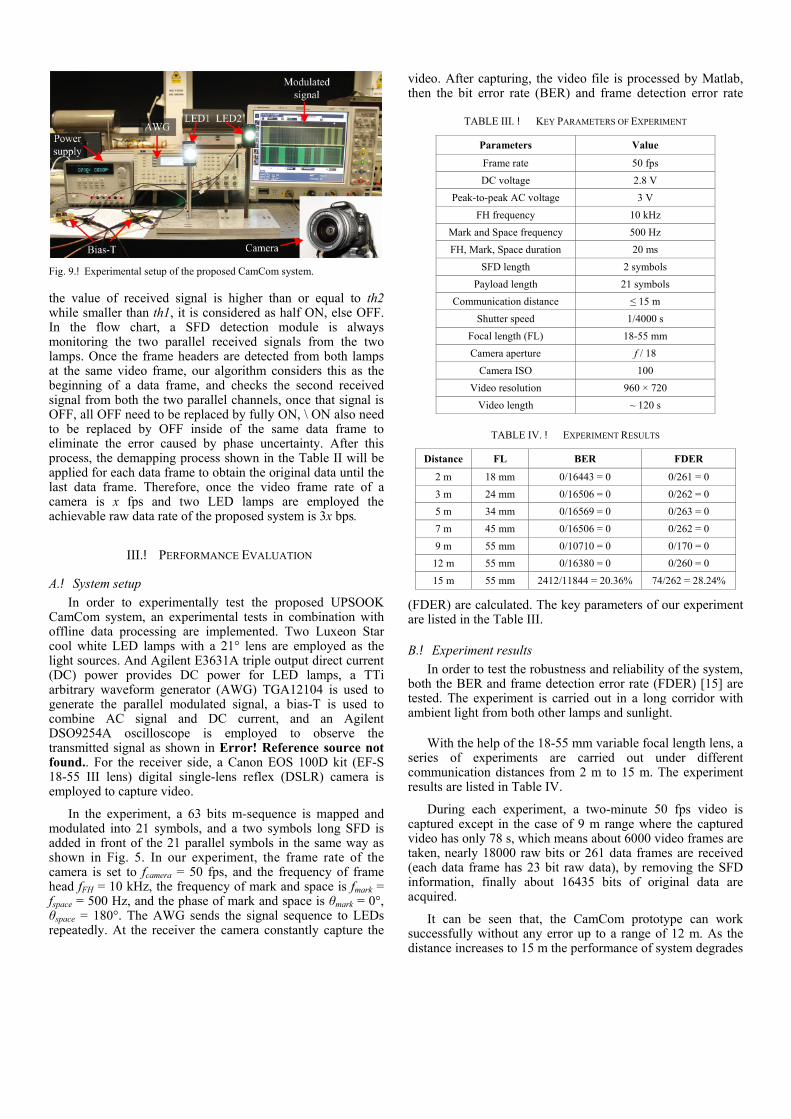
CamCom system, an experimental tests in combination with offline data processing are implemented. Two Luxeon Star cool white LED lamps with a 21° lens are employed as the light sources. And Agilent E3631A triple output direct current (DC) power provides DC power for LED lamps, a TTi arbitrary waveform generator (AWG) TGA12104 is used to generate the parallel modulated signal, a bias-T is used to combine AC signal and DC current, and an Agilent DSO9254A oscilloscope is employed to observe the transmitted signal as shown in Error! Reference source not found.. For the receiver side, a Canon EOS 100D kit (EF-S 18-55 III lens) digital single-lens reflex (DSLR) camera is employed to capture video.
In the experiment, a 63 bits m-sequence is mapped and modulated into 21 symbols, and a two symbols long SFD is added in front of the 21 parallel symbols in the same way as shown in Fig. 5. In our experiment, the frame rate of the camera is set to fcamera = 50 fps, and the frequency of frame head fFH = 10 kHz, the frequency of mark and space is fmark = fspace = 500 Hz, and the phase of mark and space is θmark = 0°, θspace = 180°. The AWG sends the signal sequence to LEDs repeatedly. At the receiver the camera constantly capture the
video. After capturing, the video file is processed by Matlab, then the bit error rate (BER) and frame detection error rate
TABLE III. KEY PARAMETERS OF EXPERIMENT
Parameters Value
Frame rate 50 fps DC voltage 2.8 V
Peak-to-peak AC voltage 3 V FH frequency 10 kHz
Mark and Space frequency 500 Hz FH, Mark, Space duration 20 ms
SFD length 2 symbols Payload length 21 symbols
Communication distance ≤ 15 m Shutter speed 1/4000 s
Focal length (FL) 18-55 mm Camera aperture f / 18
Camera ISO 100 Video resolution 960 × 720
Video length ~ 120 s
TABLE IV. EXPERIMENT RESULTS
Distance FL BER FDER
2 m 18 mm 0/16443 = 0 0/261 = 0 3 m 24 mm 0/16506 = 0 0/262 = 0 5 m 34 mm 0/16569 = 0 0/263 = 0 7 m 45 mm 0/16506 = 0 0/262 = 0 9 m 55 mm 0/10710 = 0 0/170 = 0 12 m 55 mm 0/16380 = 0 0/260 = 0 15 m 55 mm 2412/11844 = 20.36% 74/262 = 28.24%
(FDER) are calculated. The key parameters of our experiment are listed in the Table III.
B. Experiment results In order to test the robustness and reliability of the system,
both the BER and frame detection error rate (FDER) [15] are tested. The experiment is carried out in a long corridor with ambient light from both other lamps and sunlight.
With the help of the 18-55 mm variable focal length lens, a series of experiments are carried out under different communication distances from 2 m to 15 m. The experiment results are listed in Table IV.
During each experiment, a two-minute 50 fps video is captured except in the case of 9 m range where the captured video has only 78 s, which means about 6000 video frames are taken, nearly 18000 raw bits or 261 data frames are received (each data frame has 23 bit raw data), by removing the SFD information, finally about 16435 bits of original data are acquired.
It can be seen that, the CamCom prototype can work successfully without any error up to a range of 12 m. As the distance increases to 15 m the performance of system degrades
evidently, this is because the pixel size of LED decreases as the distance increases which makes it hard to distinguish OFF, half ON and fully ON state.
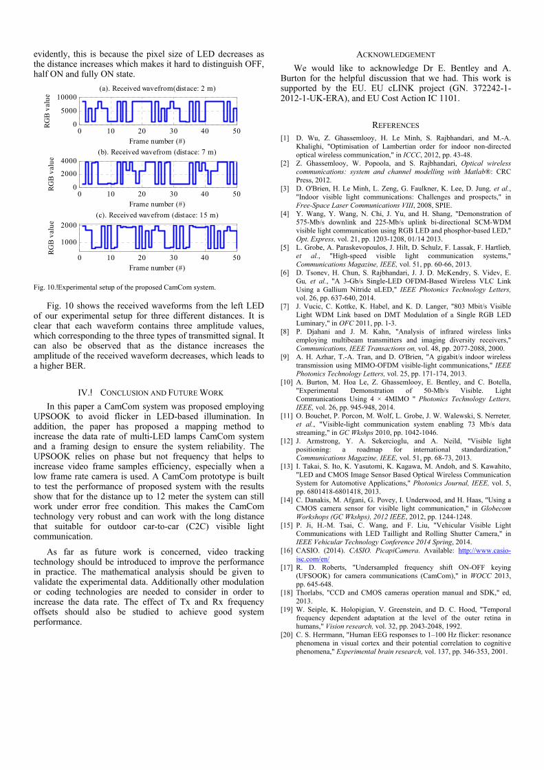
Fig. 10. Experimental setup of the proposed CamCom system.
Fig. 10 shows the received waveforms from the left LED of our experimental setup for three different distances. It is clear that each waveform contains three amplitude values, which corresponding to the three types of transmitted signal. It can also be observed that as the distance increases the amplitude of the received waveform decreases, which leads to a higher BER.
IV. CONCLUSION AND FUTURE WORK In this paper a CamCom system was proposed employing
UPSOOK to avoid flicker in LED-based illumination. In addition, the paper has proposed a mapping method to increase the data rate of multi-LED lamps CamCom system and a framing design to ensure the system reliability. The UPSOOK relies on phase but not frequency that helps to increase video frame samples efficiency, especially when a low frame rate camera is used. A CamCom prototype is built to test the performance of proposed system with the results show that for the distance up to 12 meter the system can still work under error free condition. This makes the CamCom technology very robust and can work with the long distance that suitable for outdoor car-to-car (C2C) visible light communication.
As far as future work is concerned, video tracking technology should be introduced to improve the performance in practice. The mathematical analysis should be given to validate the experimental data. Additionally other modulation or coding technologies are needed to consider in order to increase the data rate. The effect of Tx and Rx frequency offsets should also be studied to achieve good system performance.
ACKNOWLEDGEMENT We would like to acknowledge Dr E. Bentley and A.
Burton for the helpful discussion that we had. This work is supported by the EU. EU cLINK project (GN. 372242-1-2012-1-UK-ERA), and EU Cost Action IC 1101.
REFERENCES [1] D. Wu, Z. Ghassemlooy, H. Le Minh, S. Rajbhandari, and M.-A.
Khalighi, "Optimisation of Lambertian order for indoor non-directed optical wireless communication," in ICCC, 2012, pp. 43-48.
[2] Z. Ghassemlooy, W. Popoola, and S. Rajbhandari, Optical wireless communications: system and channel modelling with Matlab®: CRC Press, 2012.
[3] D. O'Brien, H. Le Minh, L. Zeng, G. Faulkner, K. Lee, D. Jung, et al., "Indoor visible light communications: Challenges and prospects," in Free-Space Laser Communications VIII, 2008, SPIE.
[4] Y. Wang, Y. Wang, N. Chi, J. Yu, and H. Shang, "Demonstration of 575-Mb/s downlink and 225-Mb/s uplink bi-directional SCM-WDM visible light communication using RGB LED and phosphor-based LED," Opt. Express, vol. 21, pp. 1203-1208, 01/14 2013.
[5] L. Grobe, A. Paraskevopoulos, J. Hilt, D. Schulz, F. Lassak, F. Hartlieb, et al., "High-speed visible light communication systems," Communications Magazine, IEEE, vol. 51, pp. 60-66, 2013.
[6] D. Tsonev, H. Chun, S. Rajbhandari, J. J. D. McKendry, S. Videv, E. Gu, et al., "A 3-Gb/s Single-LED OFDM-Based Wireless VLC Link Using a Gallium Nitride uLED," IEEE Photonics Technology Letters, vol. 26, pp. 637-640, 2014.
[7] J. Vucic, C. Kottke, K. Habel, and K. D. Langer, "803 Mbit/s Visible Light WDM Link based on DMT Modulation of a Single RGB LED Luminary," in OFC 2011, pp. 1-3.
[8] P. Djahani and J. M. Kahn, "Analysis of infrared wireless links employing multibeam transmitters and imaging diversity receivers," Communications, IEEE Transactions on, vol. 48, pp. 2077-2088, 2000.
[9] A. H. Azhar, T.-A. Tran, and D. O'Brien, "A gigabit/s indoor wireless transmission using MIMO-OFDM visible-light communications," IEEE Photonics Technology Letters, vol. 25, pp. 171-174, 2013.
[10] A. Burton, M. Hoa Le, Z. Ghassemlooy, E. Bentley, and C. Botella, "Experimental Demonstration of 50-Mb/s Visible. Light Communications Using 4 × 4MIMO " Photonics Technology Letters, IEEE, vol. 26, pp. 945-948, 2014.
[11] O. Bouchet, P. Porcon, M. Wolf, L. Grobe, J. W. Walewski, S. Nerreter, et al., "Visible-light communication system enabling 73 Mb/s data streaming," in GC Wkshps 2010, pp. 1042-1046.
[12] J. Armstrong, Y. A. Sekercioglu, and A. Neild, "Visible light positioning: a roadmap for international standardization," Communications Magazine, IEEE, vol. 51, pp. 68-73, 2013.
[13] I. Takai, S. Ito, K. Yasutomi, K. Kagawa, M. Andoh, and S. Kawahito, "LED and CMOS Image Sensor Based Optical Wireless Communication System for Automotive Applications," Photonics Journal, IEEE, vol. 5, pp. 6801418-6801418, 2013.
[14] C. Danakis, M. Afgani, G. Povey, I. Underwood, and H. Haas, "Using a CMOS camera sensor for visible light communication," in Globecom Workshops (GC Wkshps), 2012 IEEE, 2012, pp. 1244-1248.
[15] P. Ji, H.-M. Tsai, C. Wang, and F. Liu, "Vehicular Visible Light Communications with LED Taillight and Rolling Shutter Camera," in IEEE Vehicular Technology Conference 2014 Spring, 2014.
[17] R. D. Roberts, "Undersampled frequency shift ON-OFF keying (UFSOOK) for camera communications (CamCom)," in WOCC 2013, pp. 645-648.
[18] Thorlabs, "CCD and CMOS cameras operation manual and SDK," ed, 2013.
[19] W. Seiple, K. Holopigian, V. Greenstein, and D. C. Hood, "Temporal frequency dependent adaptation at the level of the outer retina in humans," Vision research, vol. 32, pp. 2043-2048, 1992.
[20] C. S. Herrmann, "Human EEG responses to 1–100 Hz flicker: resonance phenomena in visual cortex and their potential correlation to cognitive phenomena," Experimental brain research, vol. 137, pp. 346-353, 2001.