47
Understanding & Logging Electrical Power & Energy We’ll start at 11:00 AM EST Welcome To: CopyrightΘ 2020 Chauvin ArnouxΘ, Ιnc. d..b.a. AEMC Instruments

Understanding & Logging
Electrical Power & Energy
We’ll start at 11:00 AM EST
Welcome To:
CopyrightΘ 2020 Chauvin ArnouxΘ, Ιnc. d..b.a. AEMC Instruments

Understanding & Logging
Electrical Power & Energy
Mark Gutekunst, Mid Atlantic Sales Engineer
Training Webinars
• Bi-monthly webinar subjects include;
▪ Testing Insulation Resistance
▪ Remote Power Monitoring and NEC 220.87
▪ Introduction to Power Quality
• In-person & On-line Understanding Ground Resistance
Testing training – see AEMC website for times and costs
• Private training seminars – ask your AEMC Sales Engineer
for more information.

What is Electrical Energy
• Electrical Energy is what powers
all our electrical devices. The use
of this energy is metered by
electrical utilities and measured in
Watt-hours (Wh), This is what you
get billed for.
Power vs. Energy
• Power and Energy are related, but different
• Power – measured in Watts and is rate of how much
electrical energy a device instantaneously consumes.
• Energy – measured in Watt-hours, is the accumulated
use of power over time

• When a 100 watt light is turned on:• It begins to draw current from the utility.
• If the light stays on for an hour, the utility bills you for
100 Watt-hours
• If the light only stayed on for ½ an hour, the utility bills
you for 50 Watt-hours.
Power vs. Energy

• In a Single Phase System, a pair of voltage leads (L1 and
Neutral) are used to monitor the voltage and 1 CT (Current
Transducer) is used to monitor the current.
• In Split phase systems, 3 voltage leads are used (L1, L2,
Neutral) to monitor the voltage and 2 CT’s are used to monitor
the currents.
• In 3 phase / 3 wire systems, 3 voltage leads (L1, L2, L3) and
used to monitor voltages and 1 or 2 CT’s are used to monitor
currents.
• In 3 phase / 4 wire systems, 4 voltage leads (L1, L2, L3, &
Neutral) are used to monitor voltages and 3 or 4 CT’s are used
to monitor currents.
Power vs. Energy

Why Would You Want To
Record Energy• Energy is what our utility bills us for (in addition to other
things such as PF, Peak Demand, Harmonics, etc.)
• Energy is always one of the most significant operational
costs of any facility.
• Lowering Energy usage reduces operating expenses.
• Using energy efficient devices or turning off unused
devices can significantly reduce energy usage and
therefore operating costs.
• KEY: YOU NEED TO KNOW WHAT IS BEING
USED BEFORE YOU CAN PLAN WHAT TO DO

Let’s Look a Single-Phase System
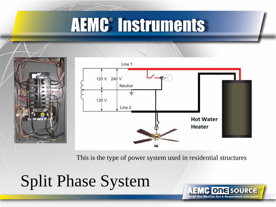
Split Phase System
This is the type of power system used in residential structures
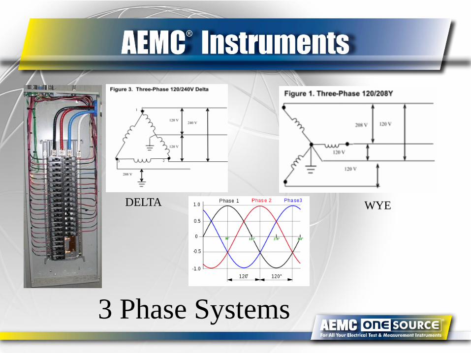
3 Phase Systems
DELTA WYE

Types of Power
• Apparent Power - VA - Volts x Amps, power
grid must be able to supply
• Real Power - Watts - Volts x Amps x Cos ϴ,
energy consumed by resistive load
• Reactive Power - VARS - Volts x Amps x Sin ϴ,
energy stored in the inductor or capacitor
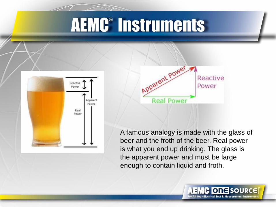
A famous analogy is made with the glass of
beer and the froth of the beer. Real power
is what you end up drinking. The glass is
the apparent power and must be large
enough to contain liquid and froth.

When The Load is Resistive
• Devices like incandescent light bulbs
• Phase angle ϴ is 0 degrees and VA = Watts,
• Real Power equals Apparent Power
• Power Factor = 1
• All energy is converted to work
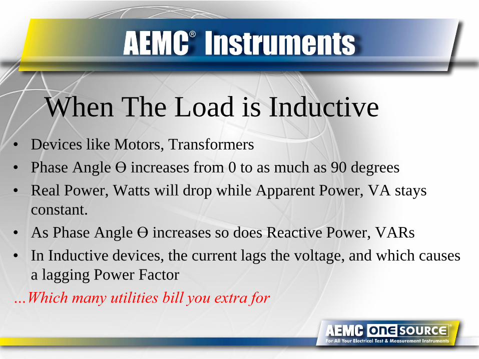
When The Load is Inductive• Devices like Motors, Transformers
• Phase Angle ϴ increases from 0 to as much as 90 degrees
• Real Power, Watts will drop while Apparent Power, VA stays
constant.
• As Phase Angle ϴ increases so does Reactive Power, VARs
• In Inductive devices, the current lags the voltage, and which causes
a lagging Power Factor
…Which many utilities bill you extra for

When The load is Capacitive• Devices like Computers, LED lights
• Phase Angle ϴ increases from 0 to as much as 90 degrees
• Real Power, Watts will drop while Apparent Power, VA stays
constant
• As Phase Angle ϴ increases, so does Reactive Power, VARs
• In this case, the current leads the voltage, and we would have a
leading Power Factor
…Which many utilities bill you extra for

The Electricians’ FriendELI the ICE Man
In an inductive circuit the
Voltage leads the Current (ELI)
In a capacitive circuit the
Current leads the Voltage (ICE)

How do I measure & log power,
what do I need?• Device capable of measuring required phase voltages and
phase currents: single to 3 phase
• Capable of measuring True RMS
• Memory to record Power over time frame required
• Real time clock to record Time of Day (TOD)
• Report Generation capability included
• Suitable for required CAT (voltage inpulse) rating
• Weather consideration: interior or exterior

Who Uses Energy Loggers
▪Electrical Contractors
▪Design Engineers
▪Electric Utility Technicians
▪Plant Maintenance Staff
▪Field Service Technicians
▪Consultants

Why is CAT Rating so important???
Category Description
CAT IAt the signal level
parts of electronic equipment
CAT IIAt local level environment,
Portable equipment appliances
CAT IIIAt an interior, fixed installation
distribution level of AC main power
CAT IVOutside of a building,
main power line at service level

WHAT IS CAT IV Rating???Test instruments are rated on their ability to withstand a voltage impulse, which is applied
through a specified level of resistance (See table).
The ratings are broken down by categories — CAT I, II, III, and IV.
CAT IV-rated test instruments are designed for testing on the primary supply source, which also includes
120V or 240V overhead or underground lines that power detached buildings or underground lines that
power well pumps. The CAT IV rating covers the highest and most dangerous level of transient
overvoltage electricians encounter when working on utility service equipment like exterior transformers

Use as a traditional clamp meter
Use as a wireless communicating power meter

Models Series
400 seriesModels 401 and 403 are general purposemeasures to 1000VAC/1400VDC and 1000AAC/(model 403)1500ADCModels 405 and 407 also measures Power and Harmonics
MSRP: $309 to $489
600 seriesModels 601 and 603 are general purposemeasures to 1000VAC/1400VDC and 2000AAC/(model 603)3000ADCModels 605 and 607 also measures Power and Harmonics
MSRP: $411 to $560
The models 407 and 607 can record and employ Bluetoothcommunication for Report Generation
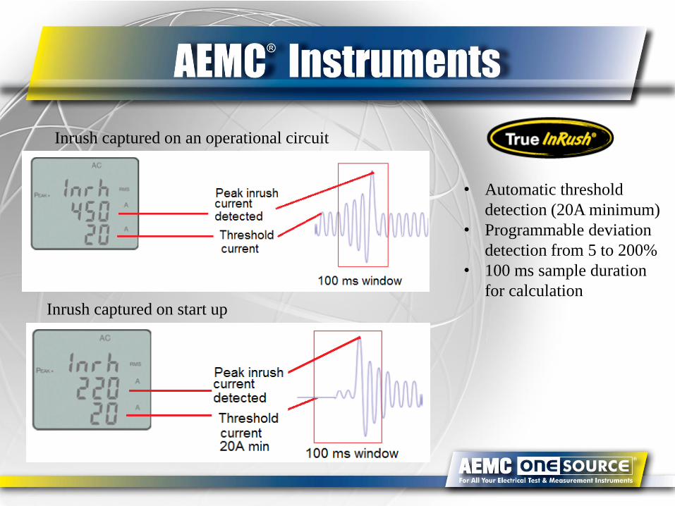
Inrush captured on an operational circuit
Inrush captured on start up
• Automatic threshold
detection (20A minimum)
• Programmable deviation
detection from 5 to 200%
• 100 ms sample duration
for calculation

AEMC Clamp-On Overview
✓ Up to 1000V CAT IV rated✓ 2000 Amp AC 3000 ADC ✓ AC+DC measurement (can measure ripple on a DC signal)✓ IP54 rated✓ Measures real, apparent and reactive power to 3 MW with 1W resolution
with 1 and 3 phase display✓ 40 to 70 and 400Hz fundamental reference for harmonic measurements✓ Bluetooth communication (model 407, 607)✓ Stores up to 1,000 measurements with user programmable storage rates✓ InRush measurement with 1mS response time and 100 ms sample
duration periods ✓ Phase rotation measurement✓ Agency approvals UL, CSA, VDE,GS and TUV✓ UL 94VO flame retardant/self extinguishing plastic✓ RoHS (Lead Free) compliance pending

Model 401,403, 405, 601,603, 605
▪ Meter
▪ Cat IV 1000V rated Silicone lead set
▪ K Thermocouple (excluding 405, 605)
▪ Set of 4 AA 1.5 V Batteries
▪ Soft case
▪ User Manual
What is Included?

Model 407 and 607
▪ Meter
▪ Cat IV 1000V rated Silicone lead set
▪ Bluetooth adaptor
▪ Set of 4 AA 1.5V Batteries
▪ Hard shell case
▪ DataView® Thumb Drive
▪ User Manual
What is Included?

Power & Energy
Loggers
PEL 102/103/105
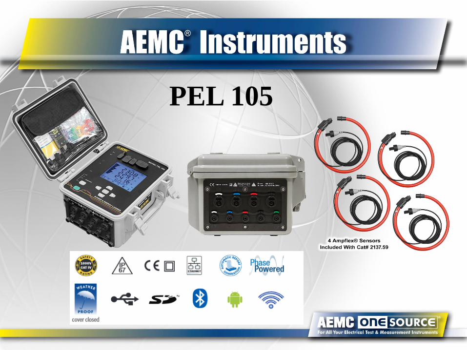
PEL 105

PEL Phase Power Adapter for Models 102 and 103▪ Powers the PEL 102/103 from phase power
▪ Powers from phase to neutral or phase to phase
▪ Provides isolation between measurement and instrument
power
▪ Range of use: Phase-to-neutral voltage: 110 to 277VAC
Phase-to-phase voltage: 110 to 480VAC
▪ Max. input voltage: Permanent: 530Vac; Transient:
550VAC
▪ Min. input voltage: 85VAC (-20%)
▪ Max. output voltage: 360V peak
▪ Frequency: 50/60Hz
▪ Consumption: 100VA max at 50/60Hz

PEL102/103/105 capabilities▪ Simple to use, minimal set up, records everything
▪ Offers all the necessary functions for Power/Energy data logging for most of the 50Hz, 60Hz,
400Hz and DC distribution systems worldwide
▪ User configurable for single phase to 3 phase Delta, Wye electrical systems, 17 electrical distribution system hook-
ups supported
▪ Direct current measurements from 200mA up to 10,000A with MA193 external current sensors
▪ Energy measurements VAh, Wh (source/load indication) and varh (including quadrant indication)
▪ Power Factor (PF), Cos (ᵠ), and Tan (ᵠ), Crest Factor and DPF measurements
▪ Harmonics up to the 50th order for 50/60 Hz voltages and currents
▪ RMS and DC measurements @ 128 samples/cycle – all phases simultaneously (16/cycle @ 400Hz)
▪ Storage of measured and calculated values on a removable SD-Card or SDHC-Card up to 32GB
▪ Automatic recognition of the connected current sensors/probes
▪ Configuration of current and voltage ratios to external PT and CT ratios
▪ USB, LAN, and Bluetooth (class 1 300 ft) communication
▪ DataView® software for data download, real-time communication with a PC and report generation with pre-written
or custom templates, included with system.
▪ Complies with NEC 220.87 monitoring requirements: Determining Existing Loads which requires monitoring
15-minute demand periods for 30 days with a recording power meter when 1 year’s historical data is not available
before upgrading the service.

Distribution Systems SupportedSingle-Phase Power Networks
►.Single-Phase 2-Wire
►.Single-Phase 3-Wire (Split-phase)
Three-Phase 3-Wire Power Networks►.Three-phase 3-wire Δ (with two current sensors)
►.Three-phase 3-wire Δ (with three current sensors)
►.Three-phase 3-wire Open Δ (with two current sensors)
►.Three-phase 3-wire Open Δ (with three current sensors)
►.Three-phase 3-wire Y (with two current sensors)
►.Three-phase 3-wire Y (with three current sensors)
►.Three-phase 3-wire Δ Balanced (with one current sensors)
Three-phase 4-Wire Y Power Networks
►.Three-phase 4-wire Y (with three current sensors)
►.Three-phase 4-wire Y Balanced►.Three-phase 4-wire Y 2½ Element
►.Three-phase 4-wire Δ►.Three-phase 4-wire Open Δ
DC Power Networks
►.DC 2-wire
►.DC 3-wire
►.DC 3-wire


PEL Physical Features – Front PanelInput Indicators
Backlit LCD
Enter Button
Navigation Button
Selection Button
Power Button
Port Indicators
PEL 102PEL 103

PEL Display

Measurement TabDataView PEL Control Panel
• Select network type
• Set PT ratio
• Select flexible probe range and number of
wraps
• Select CT ratios for specific probes and
adapters
• Select frequency/detection

DataView PEL Control Panel – Real Time Display
Displays all measurements
and calculations for:
▪ RMS measurements
▪ Power
▪ Harmonics

DataView PEL Control Panel – Recorded Data
Tool Bar
Selection Buttons
Tabular listing @
Cursor position
Movable cursor
Plot/List area
Logger Tree
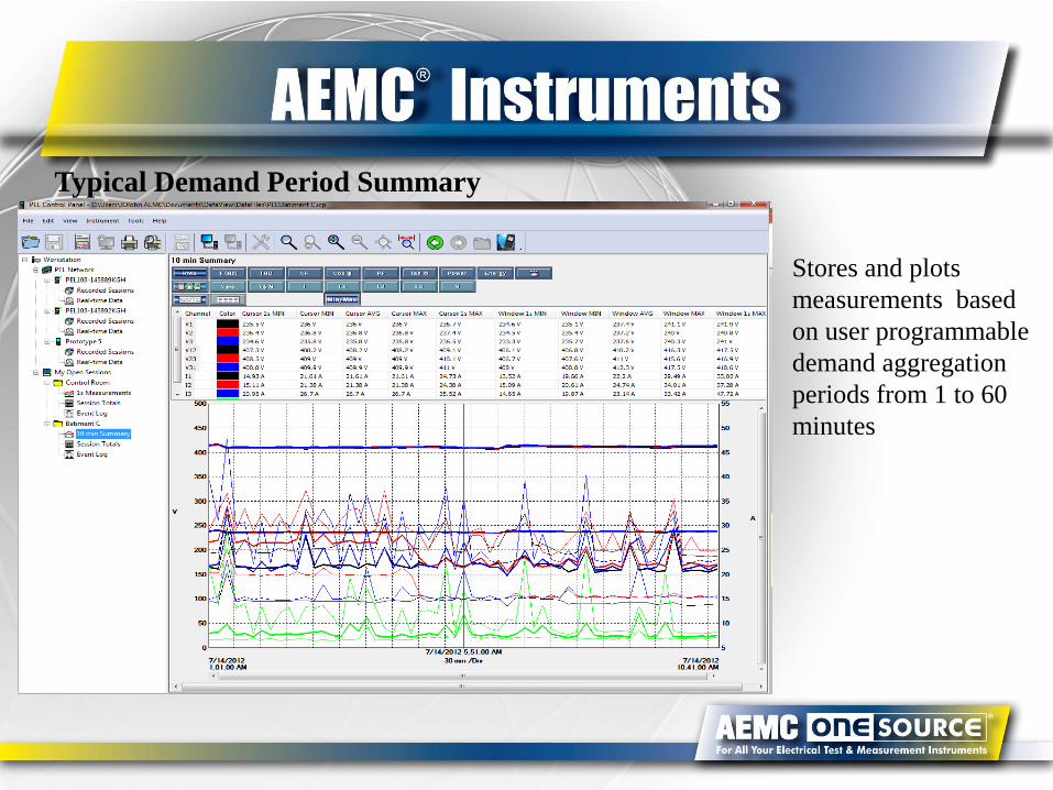
Typical Demand Period Summary
Stores and plots
measurements based
on user programmable
demand aggregation
periods from 1 to 60
minutes

Here is a typical output

Here’s another look

What is Included?
MSRP PEL102: $1795
MSRP PEL103: $1995
Phase Power Adapter MSRP: $200
MSRP PEL105: $3050

Android App Available
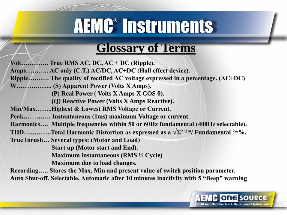
Glossary of TermsVolt…………. True RMS AC, DC, AC + DC (Ripple).
Amps……….. AC only (C.T.) AC/DC, AC+DC (Hall effect device).
Ripple………. The quality of rectified AC voltage expressed in a percentage. (AC+DC)
W…………….. (S) Apparent Power (Volts X Amps).
(P) Real Power ( Volts X Amps X COS θ).
(Q) Reactive Power (Volts X Amps Reactive).
Min/Max……..Highest & Lowest RMS Voltage or Current.
Peak…………. Instantaneous (1ms) maximum Voltage or current.
Harmonics…. Multiple frequencies within 50 or 60Hz fundamental (400Hz selectable).
THD………….Total Harmonic Distortion as expressed as a √Σ2 Hm/ Fundamental 2=%.
True Inrush… Several types: (Motor and Load)
Start up (Motor start and End).
Maximum instantaneous (RMS ½ Cycle)
Maximum due to load changes.
Recording….. Stores the Max, Min and present value of switch position parameter.
Auto Shut-off. Selectable, Automatic after 10 minutes inactivity with 5 “Beep” warning

Optional Accessories
MA193 included in base price

For More Information
Free Technical Support: Call 800-343-1391
E-mail: [email protected]
Call me - Mark Gutekunst: 508.698.5655, email:
Checkout our website: www.AEMC.com

For More Information
SE US: Chad Dugas, [email protected], 508.698. 5655
Central US: Brent McKinley, [email protected], 508.698.5649
N. Central, NE US: George Vlachos, [email protected], 508.698.5651
Central South USA: Gregg Wong: [email protected], 508.698.5652
Western US: Tim Cowgill, [email protected], 508.698.5618
CA, OR, WA: Mark Van Til, [email protected], 508.698.5654


