Ausrock 2018 The Fourth Australasian Ground Control in Mining Conference 1 Understanding and Modelling Squeezing Ground Conditions at the Ballarat Gold Mine R Talebi 1 , B Roache 2 and A Vakili 3 1. Geotechnical Engineer, Northern Star Resources Ltd, Kalgoorlie WA 6430. Email: [email protected]2. Geotechnical Manager, Mining One Consultants Pty Ltd, Melbourne VIC 3000. Email: [email protected]3. Principal Geotechnical Engineer, Mining One Consultants Pty Ltd, Melbourne VIC 3000. Email: [email protected]ABSTRACT When a highly anisotropic or weak rock mass is subjected to high-stress conditions, it can lead to large ongoing deformations or squeezing ground conditions. Squeezing ground conditions can impose increased support costs, delays associated with rehabilitation, and disruption to production schedules. Ultimately, in more severe cases, it may result in complete drive closure. Several recent case studies investigated the squeezing mechanism and measures to control squeezing ground in underground mines and also to design appropriate ground support systems. Effective management of squeezing ground conditions requires a sound understanding of the failure mechanism and the driving forces. Once the failure mechanism is understood, the appropriate ground support system should be tailored to specifically manage the critical driving forces that control the squeezing mechanism. Support type, support stiffness, reinforcement length, support density, installation times and mining sequence all have important impact on the effectiveness of the support system. This paper provides a case study at the Ballarat Gold Mine in Australia, where drive squeezing was associated with foliated ground conditions located below 700 m depth. Numerical modelling was used to better understand the failure mechanism and the driving forces that lead to squeezing conditions. The effectiveness of various support types was compared to installed ground support performance. This has provided a credible methodology for assessing and optimising the selection of reinforcement in squeezing ground conditions.
Transcript
Ausrock 2018 The Fourth Australasian Ground Control in Mining Conference
1
Understanding and Modelling Squeezing Ground Conditions at the Ballarat Gold Mine
R Talebi1, B Roache2 and A Vakili3
1. Geotechnical Engineer, Northern Star Resources Ltd, Kalgoorlie WA 6430. Email: [email protected] 2. Geotechnical Manager, Mining One Consultants Pty Ltd, Melbourne VIC 3000. Email:
[email protected] 3. Principal Geotechnical Engineer, Mining One Consultants Pty Ltd, Melbourne VIC 3000. Email:
ABSTRACT When a highly anisotropic or weak rock mass is subjected to high-stress conditions, it can lead to large ongoing deformations or squeezing ground conditions. Squeezing ground conditions can impose increased support costs, delays associated with rehabilitation, and disruption to production schedules. Ultimately, in more severe cases, it may result in complete drive closure. Several recent case studies investigated the squeezing mechanism and measures to control squeezing ground in underground mines and also to design appropriate ground support systems.
Effective management of squeezing ground conditions requires a sound understanding of the failure mechanism and the driving forces. Once the failure mechanism is understood, the appropriate ground support system should be tailored to specifically manage the critical driving forces that control the squeezing mechanism. Support type, support stiffness, reinforcement length, support density, installation times and mining sequence all have important impact on the effectiveness of the support system.
This paper provides a case study at the Ballarat Gold Mine in Australia, where drive squeezing was associated with foliated ground conditions located below 700 m depth. Numerical modelling was used to better understand the failure mechanism and the driving forces that lead to squeezing conditions. The effectiveness of various support types was compared to installed ground support performance. This has provided a credible methodology for assessing and optimising the selection of reinforcement in squeezing ground conditions.
Ausrock 2018 The Fourth Australasian Ground Control in Mining Conference
2
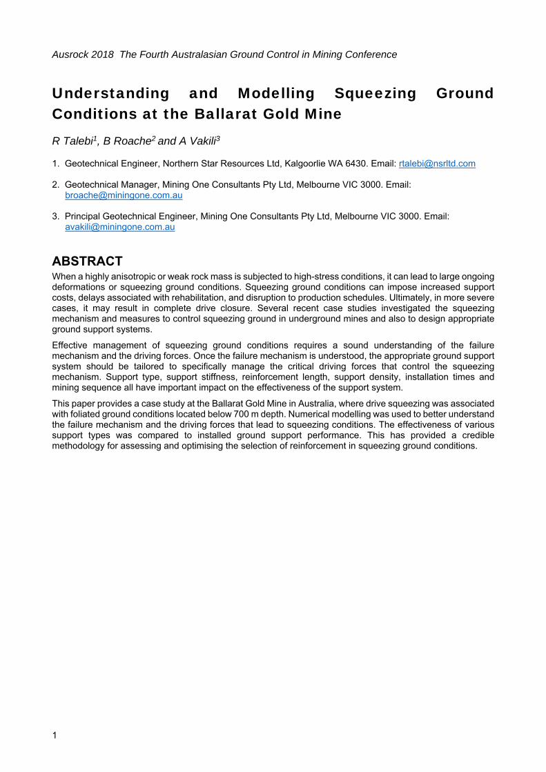
INTRODUCTION The Ballarat Gold Mine is located in Victoria, Australia, 115 km from Melbourne, see Error! Reference source not found.. Gold production re-started in 2011 under the ownership of Castlemaine Goldfields. Currently the mine produces about 46,000 ounces of gold per annum. A number of orebodies have been mined along a north-south strike to a depth of about 750 m below surface level. Mining of ore has generally been by longitudinal stoping methods.
FIG 1 Location of Ballarat Gold Mine
Squeezing ground conditions have been experienced at the Ballarat Gold Mine in defined areas, such as in the Victoria and the Llanberris mining compartments. In general, the extent of the squeezing was about 2% side wall strain which is usually manageable with one pass ground support systems. This was the case until mining commenced in the Lower Llanberris where extreme squeezing was experienced in some areas.
Experience in mines with extreme squeezing conditions has shown that it is not a realistic option to stop deformation in squeezing ground. It has been demonstrated that such an approach results in frequent rehabilitation and higher ground support costs. Many mines are pursuing a modified support strategy whereby the objective becomes one of controlling rather than arresting the degree of squeezing. Mines often use the ground support applied in more static conditions and then adapt these to the squeezing conditions. Selecting the ground support system for extreme squeezing at the Ballarat Gold Mine has used this approach. Numerical assessment has been used to understand the components of the driving forces of squeezing and displacements around the drive for Ballarat’s conditions and to help optimise rock bolt selections.
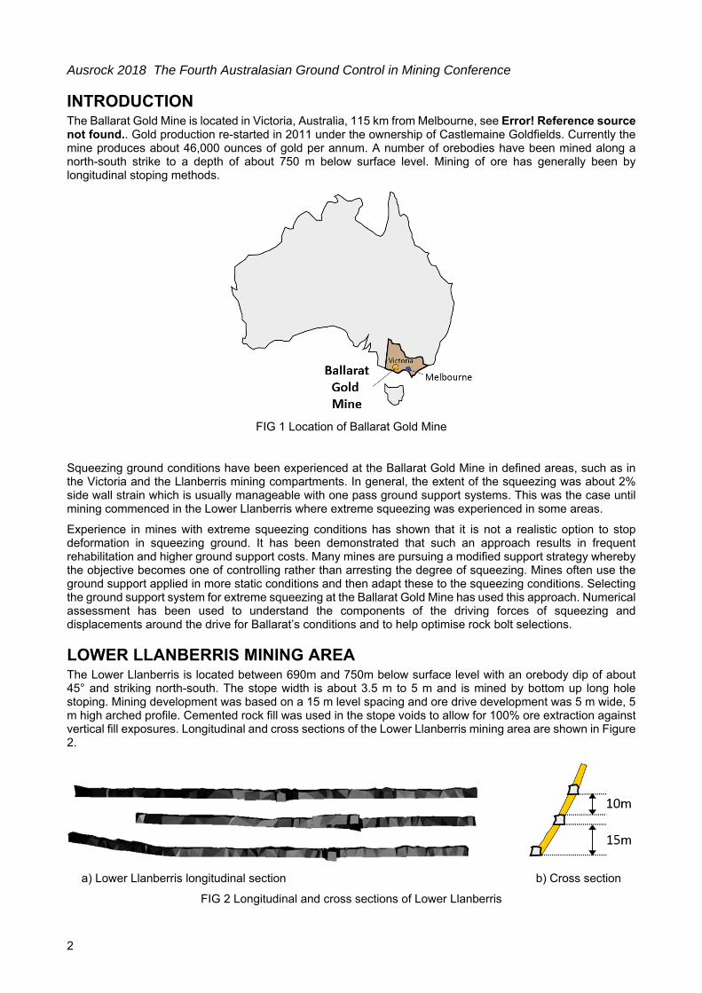
LOWER LLANBERRIS MINING AREA The Lower Llanberris is located between 690m and 750m below surface level with an orebody dip of about 45° and striking north-south. The stope width is about 3.5 m to 5 m and is mined by bottom up long hole stoping. Mining development was based on a 15 m level spacing and ore drive development was 5 m wide, 5 m high arched profile. Cemented rock fill was used in the stope voids to allow for 100% ore extraction against vertical fill exposures. Longitudinal and cross sections of the Lower Llanberris mining area are shown in Figure 2.
a) Lower Llanberris longitudinal section b) Cross section
FIG 2 Longitudinal and cross sections of Lower Llanberris
Ausrock 2018 The Fourth Australasian Ground Control in Mining Conference
3
Ground Conditions and Movements The main rock types in the Lower Llanberris are siltstone, shale and quartz. Bedding planes dominate the rock mass, which forms a steeply dipping foliation. The first ore drive development in Lower Llanberris was within fair to poor ground conditions, with localised extremely poor conditions at the intersection with major fault structures. The ore drive can be described as being positioned along a fault, with associated weak intact rock strength. The majority of ground movement was isolated to the walls, where the walls buckled and squeezed into the drive.
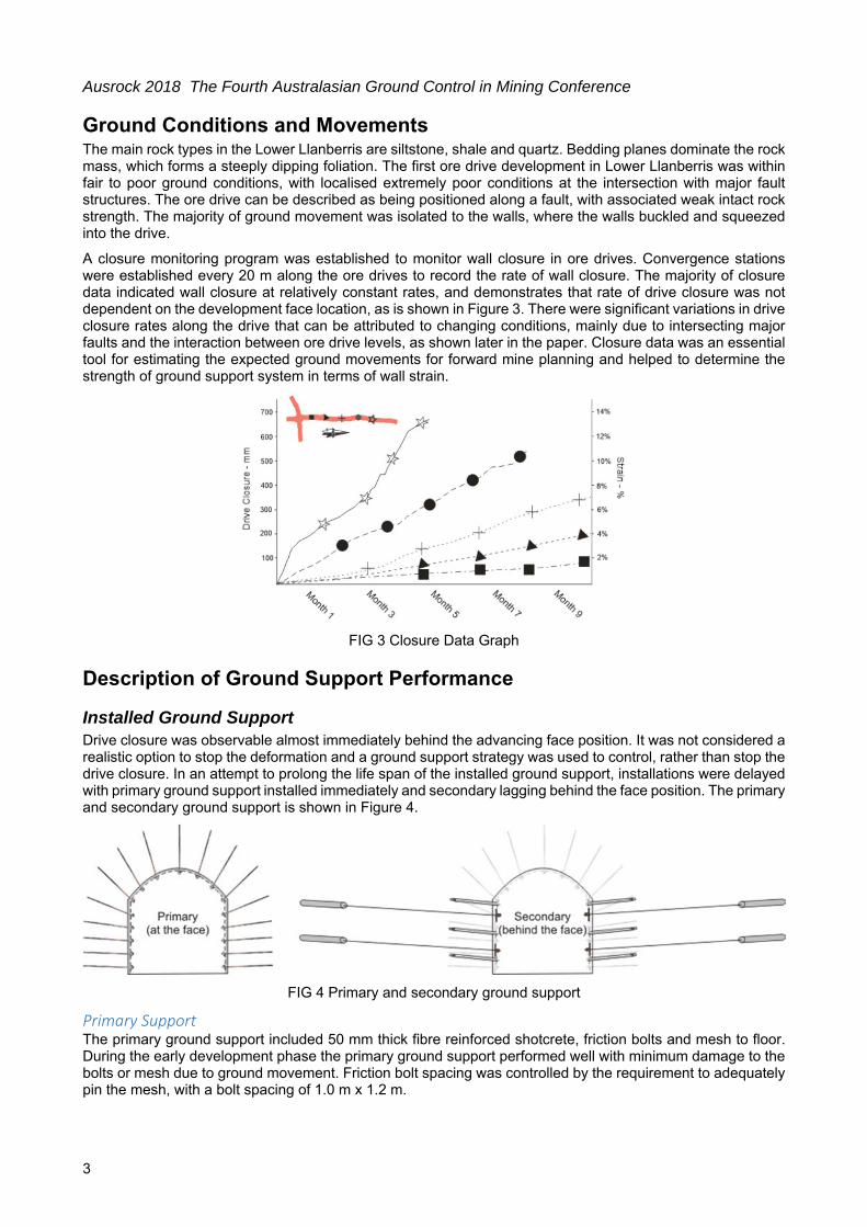
A closure monitoring program was established to monitor wall closure in ore drives. Convergence stations were established every 20 m along the ore drives to record the rate of wall closure. The majority of closure data indicated wall closure at relatively constant rates, and demonstrates that rate of drive closure was not dependent on the development face location, as is shown in Figure 3. There were significant variations in drive closure rates along the drive that can be attributed to changing conditions, mainly due to intersecting major faults and the interaction between ore drive levels, as shown later in the paper. Closure data was an essential tool for estimating the expected ground movements for forward mine planning and helped to determine the strength of ground support system in terms of wall strain.
FIG 3 Closure Data Graph
Description of Ground Support Performance
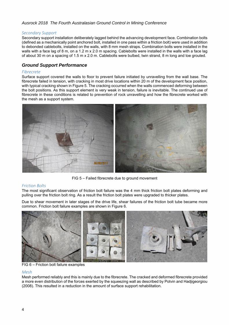
Installed Ground Support Drive closure was observable almost immediately behind the advancing face position. It was not considered a realistic option to stop the deformation and a ground support strategy was used to control, rather than stop the drive closure. In an attempt to prolong the life span of the installed ground support, installations were delayed with primary ground support installed immediately and secondary lagging behind the face position. The primary and secondary ground support is shown in Figure 4.
FIG 4 Primary and secondary ground support
Primary Support The primary ground support included 50 mm thick fibre reinforced shotcrete, friction bolts and mesh to floor. During the early development phase the primary ground support performed well with minimum damage to the bolts or mesh due to ground movement. Friction bolt spacing was controlled by the requirement to adequately pin the mesh, with a bolt spacing of 1.0 m x 1.2 m.
Ausrock 2018 The Fourth Australasian Ground Control in Mining Conference
4
Secondary Support Secondary support installation deliberately lagged behind the advancing development face. Combination bolts (defined as a mechanically point anchored bolt, installed in one pass within a friction bolt) were used in addition to debonded cablebolts, installed on the walls, with 8 mm mesh straps. Combination bolts were installed in the walls with a face lag of 8 m, on a 1.2 m x 2.0 m spacing. Cablebolts were installed in the walls with a face lag of about 30 m on a spacing of 1.5 m x 2.0 m. Cablebolts were bulbed, twin strand, 8 m long and toe grouted.
Ground Support Performance
Fibrecrete Surface support covered the walls to floor to prevent failure initiated by unravelling from the wall base. The fibrecrete failed in tension, with cracking in most drive locations within 20 m of the development face position, with typical cracking shown in Figure 5. The cracking occurred when the walls commenced deforming between the bolt positions. As this support element is very weak in tension, failure is inevitable. The continued use of fibrecrete in these conditions is related to prevention of rock unravelling and how the fibrecrete worked with the mesh as a support system.
FIG 5 – Failed fibrecrete due to ground movement
Friction Bolts The most significant observation of friction bolt failure was the 4 mm thick friction bolt plates deforming and pulling over the friction bolt ring. As a result the friction bolt plates were upgraded to thicker plates.
Due to shear movement in later stages of the drive life, shear failures of the friction bolt tube became more common. Friction bolt failure examples are shown in Figure 6.
FIG 6 – Friction bolt failure examples
Mesh Mesh performed reliably and this is mainly due to the fibrecrete. The cracked and deformed fibrecrete provided a more even distribution of the forces exerted by the squeezing wall as described by Potvin and Hadjigeorgiou (2008). This resulted in a reduction in the amount of surface support rehabilitation.
Ausrock 2018 The Fourth Australasian Ground Control in Mining Conference
5
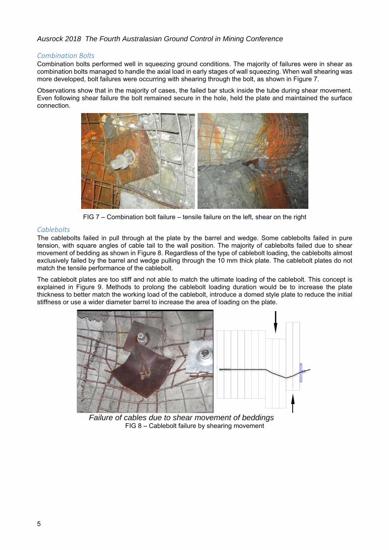
Combination Bolts Combination bolts performed well in squeezing ground conditions. The majority of failures were in shear as combination bolts managed to handle the axial load in early stages of wall squeezing. When wall shearing was more developed, bolt failures were occurring with shearing through the bolt, as shown in Figure 7.
Observations show that in the majority of cases, the failed bar stuck inside the tube during shear movement. Even following shear failure the bolt remained secure in the hole, held the plate and maintained the surface connection.
FIG 7 – Combination bolt failure – tensile failure on the left, shear on the right
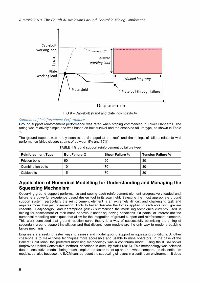
Cablebolts The cablebolts failed in pull through at the plate by the barrel and wedge. Some cablebolts failed in pure tension, with square angles of cable tail to the wall position. The majority of cablebolts failed due to shear movement of bedding as shown in Figure 8. Regardless of the type of cablebolt loading, the cablebolts almost exclusively failed by the barrel and wedge pulling through the 10 mm thick plate. The cablebolt plates do not match the tensile performance of the cablebolt.
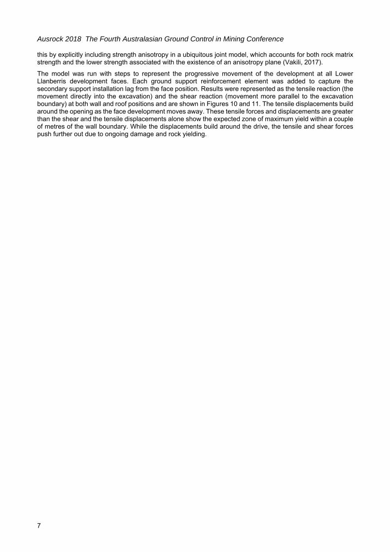
The cablebolt plates are too stiff and not able to match the ultimate loading of the cablebolt. This concept is explained in Figure 9. Methods to prolong the cablebolt loading duration would be to increase the plate thickness to better match the working load of the cablebolt, introduce a domed style plate to reduce the initial stiffness or use a wider diameter barrel to increase the area of loading on the plate.
Failure of cables due to shear movement of beddings FIG 8 – Cablebolt failure by shearing movement
Ausrock 2018 The Fourth Australasian Ground Control in Mining Conference
6
FIG 9 – Cablebolt strand and plate incompatibility
Summary of Reinforcement Performance Ground support reinforcement performance was rated when stoping commenced in Lower Llanberris. The rating was relatively simple and was based on bolt survival and the observed failure type, as shown in Table 1.
The ground support was rarely seen to be damaged at the roof, and the ratings of failure relate to wall performance (drive closure strains of between 5% and 15%).
TABLE 1 Ground support reinforcement by failure type
Application of Numerical Modelling for Understanding and Managing the Squeezing Mechanism Observing ground support performance and seeing each reinforcement element progressively loaded until failure is a powerful experience based design tool in its own right. Selecting the most appropriate ground support system, particularly the reinforcement element is an extremely difficult and challenging task and requires more than just observation. Tools to better describe the forces applied to each rock bolt type are essential. Hadjigeorgiou and Karampinos (2017) summarised the modelling techniques currently used in mining for assessment of rock mass behaviour under squeezing conditions. Of particular interest are the numerical modelling techniques that allow for the integration of ground support and reinforcement elements. This work concluded that ground reaction curve theory is a way of successfully optimising the timing of secondary ground support installation and that discontinuum models are the only way to model a buckling failure mechanism.
Engineers are seeking faster ways to assess and model ground support in squeezing conditions. Another challenge is to make these techniques more accessible and usable to mine operators. In the case of the Ballarat Gold Mine, the preferred modelling methodology was a continuum model, using the IUCM solver (Improved Unified Constitutive Method), described in detail by Vakili (2016). This methodology was selected due to constitutive models being much simpler and faster to set up and run when compared to discontinuum models, but also because the IUCM can represent the squeezing of layers in a continuum environment. It does
Ausrock 2018 The Fourth Australasian Ground Control in Mining Conference
7
this by explicitly including strength anisotropy in a ubiquitous joint model, which accounts for both rock matrix strength and the lower strength associated with the existence of an anisotropy plane (Vakili, 2017).
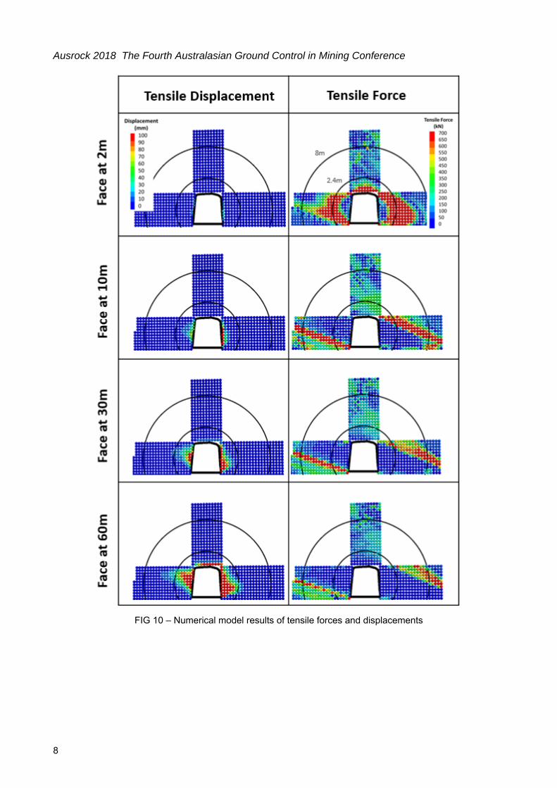
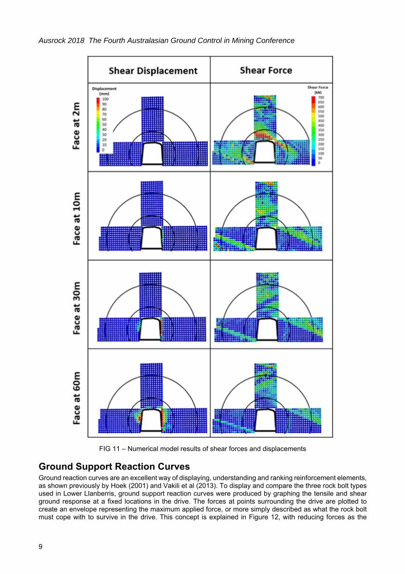
The model was run with steps to represent the progressive movement of the development at all Lower Llanberris development faces. Each ground support reinforcement element was added to capture the secondary support installation lag from the face position. Results were represented as the tensile reaction (the movement directly into the excavation) and the shear reaction (movement more parallel to the excavation boundary) at both wall and roof positions and are shown in Figures 10 and 11. The tensile displacements build around the opening as the face development moves away. These tensile forces and displacements are greater than the shear and the tensile displacements alone show the expected zone of maximum yield within a couple of metres of the wall boundary. While the displacements build around the drive, the tensile and shear forces push further out due to ongoing damage and rock yielding.
Ausrock 2018 The Fourth Australasian Ground Control in Mining Conference
8
FIG 10 – Numerical model results of tensile forces and displacements
Ausrock 2018 The Fourth Australasian Ground Control in Mining Conference
9
FIG 11 – Numerical model results of shear forces and displacements
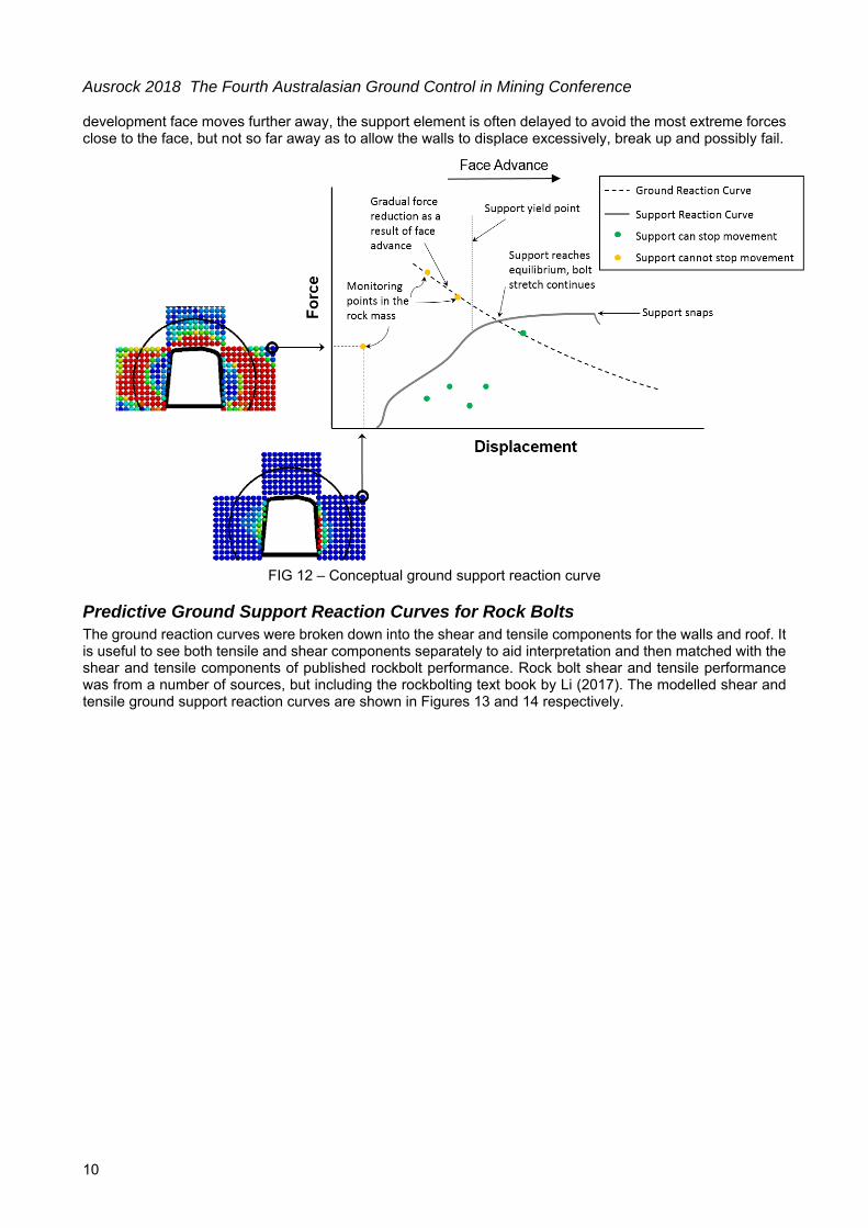
Ground Support Reaction Curves Ground reaction curves are an excellent way of displaying, understanding and ranking reinforcement elements, as shown previously by Hoek (2001) and Vakili et al (2013). To display and compare the three rock bolt types used in Lower Llanberris, ground support reaction curves were produced by graphing the tensile and shear ground response at a fixed locations in the drive. The forces at points surrounding the drive are plotted to create an envelope representing the maximum applied force, or more simply described as what the rock bolt must cope with to survive in the drive. This concept is explained in Figure 12, with reducing forces as the
Ausrock 2018 The Fourth Australasian Ground Control in Mining Conference
10
development face moves further away, the support element is often delayed to avoid the most extreme forces close to the face, but not so far away as to allow the walls to displace excessively, break up and possibly fail.
FIG 12 – Conceptual ground support reaction curve
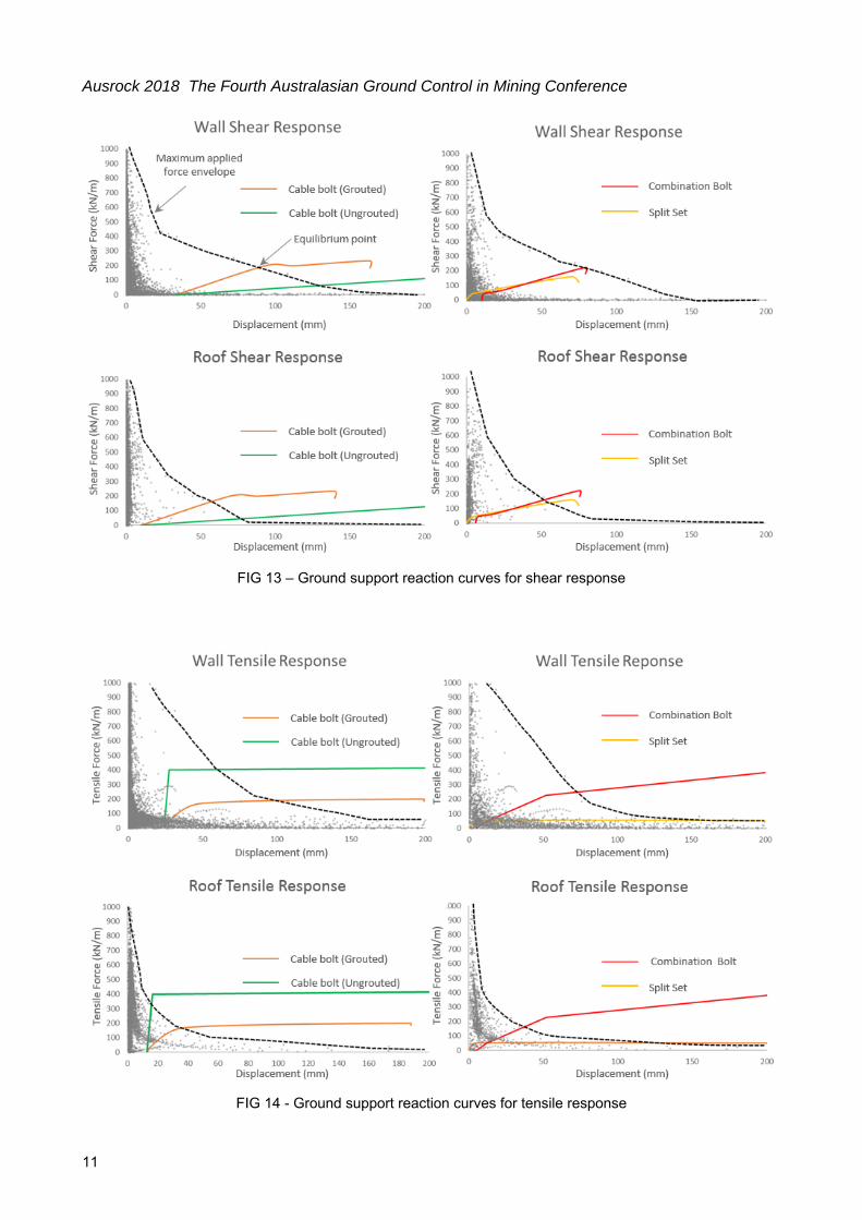
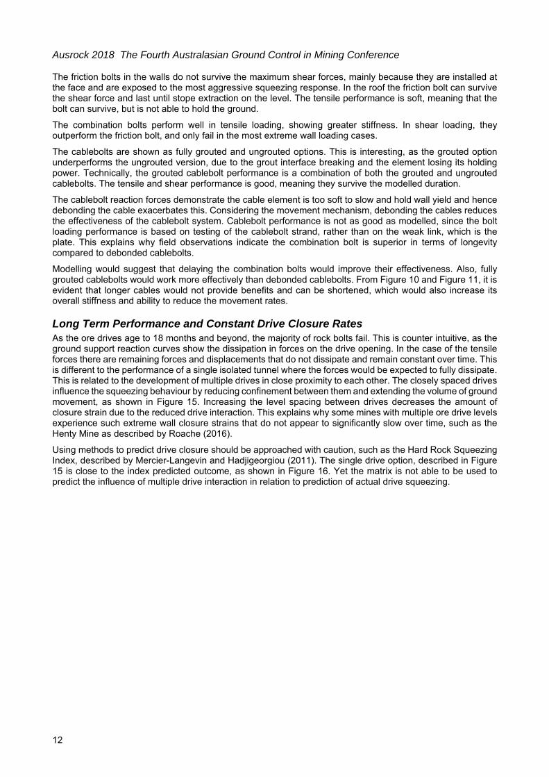
Predictive Ground Support Reaction Curves for Rock Bolts The ground reaction curves were broken down into the shear and tensile components for the walls and roof. It is useful to see both tensile and shear components separately to aid interpretation and then matched with the shear and tensile components of published rockbolt performance. Rock bolt shear and tensile performance was from a number of sources, but including the rockbolting text book by Li (2017). The modelled shear and tensile ground support reaction curves are shown in Figures 13 and 14 respectively.
Ausrock 2018 The Fourth Australasian Ground Control in Mining Conference
11
FIG 13 – Ground support reaction curves for shear response
FIG 14 - Ground support reaction curves for tensile response
Ausrock 2018 The Fourth Australasian Ground Control in Mining Conference
12
The friction bolts in the walls do not survive the maximum shear forces, mainly because they are installed at the face and are exposed to the most aggressive squeezing response. In the roof the friction bolt can survive the shear force and last until stope extraction on the level. The tensile performance is soft, meaning that the bolt can survive, but is not able to hold the ground.
The combination bolts perform well in tensile loading, showing greater stiffness. In shear loading, they outperform the friction bolt, and only fail in the most extreme wall loading cases.
The cablebolts are shown as fully grouted and ungrouted options. This is interesting, as the grouted option underperforms the ungrouted version, due to the grout interface breaking and the element losing its holding power. Technically, the grouted cablebolt performance is a combination of both the grouted and ungrouted cablebolts. The tensile and shear performance is good, meaning they survive the modelled duration.
The cablebolt reaction forces demonstrate the cable element is too soft to slow and hold wall yield and hence debonding the cable exacerbates this. Considering the movement mechanism, debonding the cables reduces the effectiveness of the cablebolt system. Cablebolt performance is not as good as modelled, since the bolt loading performance is based on testing of the cablebolt strand, rather than on the weak link, which is the plate. This explains why field observations indicate the combination bolt is superior in terms of longevity compared to debonded cablebolts.
Modelling would suggest that delaying the combination bolts would improve their effectiveness. Also, fully grouted cablebolts would work more effectively than debonded cablebolts. From Figure 10 and Figure 11, it is evident that longer cables would not provide benefits and can be shortened, which would also increase its overall stiffness and ability to reduce the movement rates.
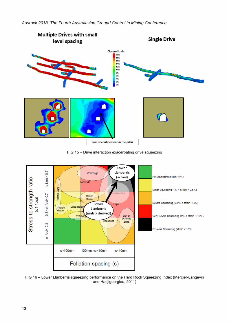
Long Term Performance and Constant Drive Closure Rates As the ore drives age to 18 months and beyond, the majority of rock bolts fail. This is counter intuitive, as the ground support reaction curves show the dissipation in forces on the drive opening. In the case of the tensile forces there are remaining forces and displacements that do not dissipate and remain constant over time. This is different to the performance of a single isolated tunnel where the forces would be expected to fully dissipate. This is related to the development of multiple drives in close proximity to each other. The closely spaced drives influence the squeezing behaviour by reducing confinement between them and extending the volume of ground movement, as shown in Figure 15. Increasing the level spacing between drives decreases the amount of closure strain due to the reduced drive interaction. This explains why some mines with multiple ore drive levels experience such extreme wall closure strains that do not appear to significantly slow over time, such as the Henty Mine as described by Roache (2016).
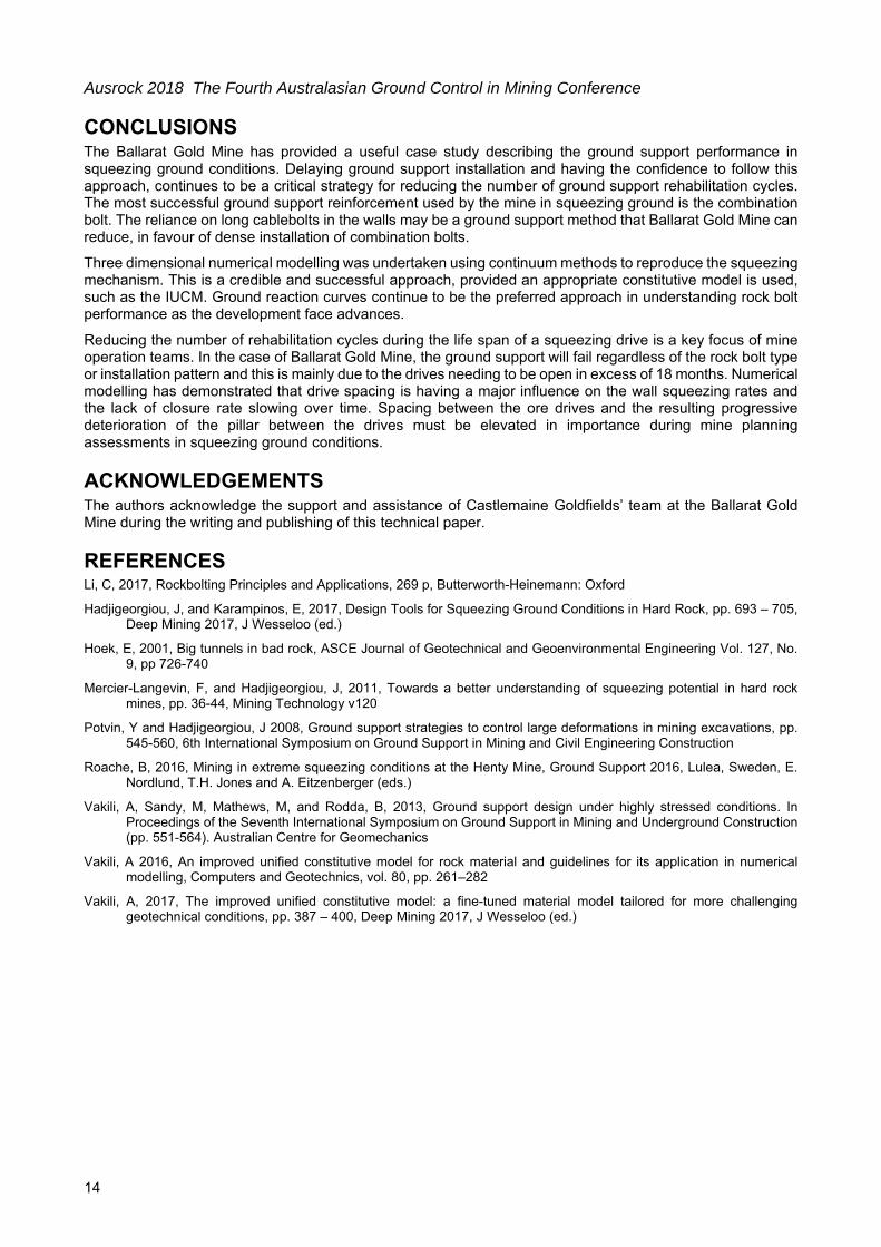
Using methods to predict drive closure should be approached with caution, such as the Hard Rock Squeezing Index, described by Mercier-Langevin and Hadjigeorgiou (2011). The single drive option, described in Figure 15 is close to the index predicted outcome, as shown in Figure 16. Yet the matrix is not able to be used to predict the influence of multiple drive interaction in relation to prediction of actual drive squeezing.
Ausrock 2018 The Fourth Australasian Ground Control in Mining Conference
FIG 16 – Lower Llanberris squeezing performance on the Hard Rock Squeezing Index (Mercier-Langevin and Hadjigeorgiou, 2011)
Ausrock 2018 The Fourth Australasian Ground Control in Mining Conference
14
CONCLUSIONS The Ballarat Gold Mine has provided a useful case study describing the ground support performance in squeezing ground conditions. Delaying ground support installation and having the confidence to follow this approach, continues to be a critical strategy for reducing the number of ground support rehabilitation cycles. The most successful ground support reinforcement used by the mine in squeezing ground is the combination bolt. The reliance on long cablebolts in the walls may be a ground support method that Ballarat Gold Mine can reduce, in favour of dense installation of combination bolts.
Three dimensional numerical modelling was undertaken using continuum methods to reproduce the squeezing mechanism. This is a credible and successful approach, provided an appropriate constitutive model is used, such as the IUCM. Ground reaction curves continue to be the preferred approach in understanding rock bolt performance as the development face advances.
Reducing the number of rehabilitation cycles during the life span of a squeezing drive is a key focus of mine operation teams. In the case of Ballarat Gold Mine, the ground support will fail regardless of the rock bolt type or installation pattern and this is mainly due to the drives needing to be open in excess of 18 months. Numerical modelling has demonstrated that drive spacing is having a major influence on the wall squeezing rates and the lack of closure rate slowing over time. Spacing between the ore drives and the resulting progressive deterioration of the pillar between the drives must be elevated in importance during mine planning assessments in squeezing ground conditions.
ACKNOWLEDGEMENTS The authors acknowledge the support and assistance of Castlemaine Goldfields’ team at the Ballarat Gold Mine during the writing and publishing of this technical paper.
Hadjigeorgiou, J, and Karampinos, E, 2017, Design Tools for Squeezing Ground Conditions in Hard Rock, pp. 693 – 705, Deep Mining 2017, J Wesseloo (ed.)
Hoek, E, 2001, Big tunnels in bad rock, ASCE Journal of Geotechnical and Geoenvironmental Engineering Vol. 127, No. 9, pp 726-740
Mercier-Langevin, F, and Hadjigeorgiou, J, 2011, Towards a better understanding of squeezing potential in hard rock mines, pp. 36-44, Mining Technology v120
Potvin, Y and Hadjigeorgiou, J 2008, Ground support strategies to control large deformations in mining excavations, pp. 545-560, 6th International Symposium on Ground Support in Mining and Civil Engineering Construction
Roache, B, 2016, Mining in extreme squeezing conditions at the Henty Mine, Ground Support 2016, Lulea, Sweden, E. Nordlund, T.H. Jones and A. Eitzenberger (eds.)
Vakili, A, Sandy, M, Mathews, M, and Rodda, B, 2013, Ground support design under highly stressed conditions. In Proceedings of the Seventh International Symposium on Ground Support in Mining and Underground Construction (pp. 551-564). Australian Centre for Geomechanics
Vakili, A 2016, An improved unified constitutive model for rock material and guidelines for its application in numerical modelling, Computers and Geotechnics, vol. 80, pp. 261–282
Vakili, A, 2017, The improved unified constitutive model: a fine-tuned material model tailored for more challenging geotechnical conditions, pp. 387 – 400, Deep Mining 2017, J Wesseloo (ed.)