Understanding Carbon Monoxide Capture Using Metal−OrganicFrameworksAna Martín-Calvo, Francisco D. Lahoz-Martín, and Sofía Calero*1Department of Physical, Chemical, and Natural Systems, University Pablo de Olavide, Carretera de Utrera km. 1, 41013 Seville, Spain
*S Supporting Information
ABSTRACT: We have used molecular simulations to analyze the effect of water onthe adsorption of carbon monoxide in metal−organic frameworks. We have developeda model for carbon monoxide that not only reproduces the required experimentalproperties more accurately than previous models, but also takes into account the effectof the dipole moment on the interaction of the molecule with water and with themetal−organic framework. Our simulations were performed for Cu-BTC and IRMOF-1 with different contents of water, up to the highest water loading that each metal−organic framework can contain without losing stability. To carry out this study, wecomputed the entropies and energies of adsorption, the Henry coefficients, theadsorption isotherms in the dry and hydrated structures, and the moleculardistributions of carbon monoxide based on the topology of the framework and onthe interactions with the molecules of water. Our results show that the adsorption ofcarbon monoxide can be increased or decreased by controlling the amount of water inthe structures.
1. INTRODUCTIONMetal−organic frameworks (MOFs) are porous materialsconsisting on metallic centers linked by organic ligands. Theirvariety of pores and cavities with different sizes and shapesmake these materials good candidates for storage andseparation processes. Among metal−organic frameworks, Cu-BTC and IRMOF-1 are two of the most studied structures.1−3
Cu-BTC was first synthesized by Chui et al.4 as a metalcoordination polymer based on copper centers and 1,3,5-benzenetricarboxylate (BTC) linker molecules. This conforma-tion generates a cubic structure characterized by small and largecages connected by windows. There are two alternating types oflarge cages: one with its inner surface composed of benzenerings from BTC with their 6-fold axes pointing toward thecenter of the pore and one in which the inner surface is notformed by the rings of BTC.5
IRMOF-1 is the smallest structure from the family ofisoreticular metal−organic frameworks (IRMOFs) and was firstreported by the group of Yaghi.6,7 This structure is formed byZn4O(CO2)6 units linked by phenylene ligands. The linkage ofthe Zn4O complexes is forced to alternate between linkerspointing outward and inward, resulting in a structure with twoalternating types of cavities: small cavities with diameters ofabout 11 Å and large cavities with diameters of about 15 Å.7
The aim of this work was to analyze the effect that thepresence of water exerts in the Cu-BTC and IRMOF-1structures in terms of the capture of carbon monoxide.Therefore, it was important to first evaluate the stabilities ofCu-BTC and IRMOF-1 in the presence of water. The stabilityof Cu-BTC in water is still an open subject. Li and Yangreported that Cu-BTC is stable after water adsorption,8 whereas
Liang et al.9 reported the opposite and mentioned that thestability found by Li and Yang might be attributable to relativelyrapid adsorption/desorption cycles used in their experiments.Following the same line of thought, Liu et al. suggested that thehydrothermal stability of Cu-BTC is prone to decrease afterheat treatment and water vapor adsorption.10 On the otherhand, Henninger et al.11 showed water loading capacities in Cu-BTC about 324 g/kg for higher desorption temperatures. In avery recent work, Gul-E-Noor et al.12 reported that thepresence of water in Cu-BTC leads to the decomposition of thestructure. Kusgens et al. concluded that, despite its instabilityupon direct exposure to water, Cu-BTC is a promising materialin trace water removal.13 In a theoretical study Grajciar et al.14
observed that the structure of Cu-BTC with one or twomolecules of water per paddle wheel remains relativelyunchanged. However, they also showed that the stability variesfor different water contents and different decompositionproducts. Taken together, these works indicate that Cu-BTCcan be considered relatively stable upon hydration/dehydrationat room temperature and for the water contents considered inthis work.8,15,16
Regarding IRMOF-1, it is well-known that this structure isvery sensitive to water, losing its high surface area afterprolonged exposure to humid air.17 An important point is that,at low water, content the structure is maintained despite adecrease of the lattice parameter. Only water quantities higherthan 4% make the structure clearly unstable.18 Recent studies
Received: December 1, 2011Revised: February 16, 2012Published: February 21, 2012
have provided evidence that, at low water contents, themolecules of water are isolated in the lattice, but at around 6.6wt % water, the basicity of water after solvation and the largecoordination spheres of zinc provoke an irreversible latticedisruption by displacement of the organic ligand.19,20
Several works have studied adsorption and separationprocesses in Cu-BTC and IRMOF-1 for gases of environmentalinterest such as carbon dioxide, nitrogen, and hydrocarbons, aswell as their mixtures.21−33 These studies note the importanceof performing adsorption analysis in searching for an optimalseparation or storage of these gases. However, despite theimportance of carbon monoxide, as a byproduct from theincomplete combustion of gasoline, oil, gas, and carbon, amongothers, only a few works have provided insight into the captureor separation of this molecule using MOFs.34−43
Only two models of carbon monoxide have been reported inthe literature. The first model was proposed by Piper et al. in1984 for the study of solid CO−Ar systems.44 The secondmodel was developed by Straub and Karplus seven years laterfor the analysis of the photodissociation of carbon monoxidefrom myoglobin.45 These models have been applied to otherstudies with reasonable agreement with experimentaldata.36,39,40,42 However, none of the previous works were ableto reproduce the experimental vapor−liquid equilibrium curveof the molecules, and this is a crucial property for the accuratereproduction of adsorption in confined systems.46−51 Anadditional option for these models is the use of the genericuniversal force field (UFF)52 to mimic the molecule.Sirjoosingh et al. employed this strategy for the separation ofcarbon monoxide from carbon dioxide using ZIF-68 and ZIF-69 structures.36 The use of the generic force field to mimiccarbon monoxide is limited by the point charges that must beassigned to atoms that are not included in the UFF model. Thepoint charges used with this force field were computed usingthe Mulliken analysis and correspond to 0.107 e for the carbonatom and −0.107 e for the oxygen atom. These charges lead toa dipole moment of 0.58 D, whereas the experimental value forcarbon monoxide is 0.112 D.53
In this work, we analyzed the effect of water on theadsorption of carbon monoxide in Cu-BTC and IRMOF-1.Because water is a very polar molecule (1.85 D), a model forcarbon monoxide with the correct dipole moment seemsimportant. Therefore, we developed a new model for thecarbon monoxide molecule that not only reproduces thevapor−liquid equilibrium curve, the vapor pressure curve, andthe bulk density for a wide range of temperatures, but alsoprovides a dipole moment of 0.112 D. Using this model, weanalyzed the adsorption properties of carbon monoxide in Cu-BTC and IRMOF-1 as dehydrated and hydrated structures.This model and methodology used for our study are detailed insection 2. The obtained results are discussed in section 3, andthe most relevant conclusions are summarized in section 4.
2. METHODOLOGYWe used Gibbs-ensemble Monte Carlo simulations to computethe vapor−liquid equilibrium curve of carbon monoxide.During the simulations, the Lennard-Jones parameters of thecarbon monoxide model were fitted to reproduce theexperimental curve.54 This is the first and the most importantstep in the performance of adsorption studies in poroussystems.46−51 We mimicked the carbon monoxide moleculeswith a rigid model characterized by a bond length of 1.128 Åbetween the carbon and oxygen atoms. The atoms had partial
charges of −0.2424 and −0.2744 e, respectively. A dummyatom with a point charge of 0.517 e is located 0.6443 Å fromthe carbon atom, to reproduce the experimental dipole momentof the molecule (0.112 D).53 In addition, we performed Gibbs-ensemble Monte Carlo simulations with the models proposedby Piper et al.44 and by Straub and Karplus.45 The first model ischaracterized by four interaction centers: the carbon andoxygen atoms, with positive and null partial charges,respectively, and two sites that provide negative charges tothe molecule, giving a dipole moment of 0.43 D. The modelreported of Straub and Karplus is similar to that proposed inthis work. It is based on three interaction centers: the carbonand oxygen atoms, both with negative charges, and a positivelycharged dummy atom to compensate these charges, resulting ina dipole moment of 0.35 D. Details of these models are listed inTable 1.
To simulate water molecules, we used the Tip5pEw model.55
This model was parametrized for being used with the Ewaldsummation method, and it has been successfully applied inprevious works, providing results for water that are in goodagreement with experimental data.16,55
We considered the Cu-BTC and IRMOF-1 frameworks to berigid and to interact with carbon monoxide by Lennard-Jonesand Coulombic potentials. The Lennard-Jones parameters weretaken from the DREIDING generic force field,56 except that forcooper, which was taken from UFF.52 The charges for IRMOF-1 were obtained from Frost et al.57 As the goal of this study wasto analyze the effect of the presence of water in the structure forcarbon monoxide capture, we used a set of charges previouslyvalidated for Cu-BTC that provides the best agreement withexperimental values of water adsorption in this structure.16
Simulations were performed for one unit cell of a = b = c =26.343 Å for Cu-BTC and a = b = c = 25.832 Å for IRMOF-1.The computed helium void fractions were 0.76 for Cu-BTCand 0.82 for IRMOF-1. The full sets of parameters and chargeframeworks used in this work for the frameworks are listed inthe Supporting Information (Table S1).The adsorbate−adsorbate and adsorbate−framework inter-
actions were modeled with Lennard-Jones parameters andCoulombic potentials. The Lennard-Jones parameters wereobtained from Lorentz−Berthelot mixing rules, except for theinteractions between carbon monoxide and Cu-BTC, for whichthe Lennard-Jones parameters are listed in Table S2 of the
Table 1. Lennard-Jones Parameters, Partial Charges, andBond Lengths for the Models of Carbon MonoxideConsidered in This Work
this work C 3.636 16.141 −0.2424 0O 2.979 98.014 −0.2744 1.128site − − 0.5168 0.6443
The Journal of Physical Chemistry C Article
dx.doi.org/10.1021/jp211563e | J. Phys. Chem. C 2012, 116, 6655−66636656
Supporting Information. Coulombic potentials were obtainedby using the Ewald summation method.To compute the adsorption isotherms, we used grand-
canonical Monte Carlo (GCMC) simulations fixing thechemical potential, volume, and temperature. The pressurewas obtained from the fugacity using the Peng−Robinsonequation of state. As Monte Carlo moves, we used translation,rotation, regrowth at a random position, and reinsertion. Tocompare our results with available experimental isotherms,absolute (abs) adsorptions were converted to excess (exc)adsorptions using the expression58
= − PVzRT
adsorption adsorptionexc abs
where P is the pressure of the system, V is the pore volume ofthe structure, z is the compressibility of the gas, R is the gasconstant, and T is the temperature of the system.The Henry coefficients and heats of adsorption at zero
coverage were computed using Monte Carlo in the NVTensemble. The Henry coefficient is related to the excesschemical potential, which was computed using Widom's test-particle method. Detailed information about these methods canbe found elsewhere.59
3. RESULTS AND DISCUSSION
We computed adsorption isotherms of carbon monoxide inmetal−organic frameworks at 298 K for a range of pressuresspanning from 1 to 105 kPa. Adsorption isotherms comparingthe different models of carbon monoxide in Cu-BTC andIRMOF-1 are shown in Figure 1. The model proposed by Piperet al. provides the highest adsorption, followed by our model,the generic model using UFF, and finally by the modelproposed by Straub and Kaplus. The discrepancies amongmodels can be attributed to the different topologies of theframeworks. The sensitivity of the adsorption in the differentmodels seems to be directly related to the shape and size of thepores. To validate this theory, we performed additionalsimulations in MIL-47. This structure is characterized bychannels with a diamond shape in one direction, generated byvanadium metallic centers linked by organic ligands 1,4-benzenedicarboxylate. The group of Ferey was the first toreport this framework from the family of hybrid structurescalled MIL (Materials of the Institut Lavoisier).60 For thesimulations, we used the crystal structure from Alaerts et al.61
The simulation cell consisted of a supercell with a = 27.27 Å, b= 32.29 Å, and c = 27.88 Å. The force field was taken fromDREIDING,56 except for the value for vanadium, which wastaken from UFF.52 The atomic charges for MIL-47 were takenfrom previous works.62,63 All of these parameters are compiledin the Supporting Information (Table S1).Adsorption properties at zero coverage for carbon monoxide
in Cu-BTC, IRMOF-1, and MIL-47 are summarized in Table 2.It is interesting to highlight that, not only at zero coverage butalso at low and intermediate values of pressure (Figure 1), theadsorption seems to be rather insensitive to the model, exceptin theh case of Cu-BTC. The computed Henry coefficients andenergies and entropies of adsorption in the low-coverageregime are highly dependent on the size of the cages. Weobserved differences of up to 30% in the heat of adsorption forthe structure with small cages (Cu-BTC). However, thesedifferences were found to be negligible for structures with largercages such as IRMOF-1 and MIL-47.
At high pressure (Figure 1), the adsorption behaviorsobtained for the different models were directly related to thesize of the cage, the critical temperature, the vapor pressure,and the liquid density of the adsorbate. Hence, we obtainedhigher values of adsorption for the structure with larger cages,namely, IRMOF-1. This structure also gave larger differences inadsorption depending on the model used for the adsorbate.Although the large cages of Cu-BTC are larger in diameter thanthose of MIL-47, we found that differences in adsorption due tovariations in the carbon monoxide models were similar. Thisinteresting result is evidence that adsorption in the structures isgoverned by the combination of the size and shape of the pores.Among the different models, the one reported by Piper et
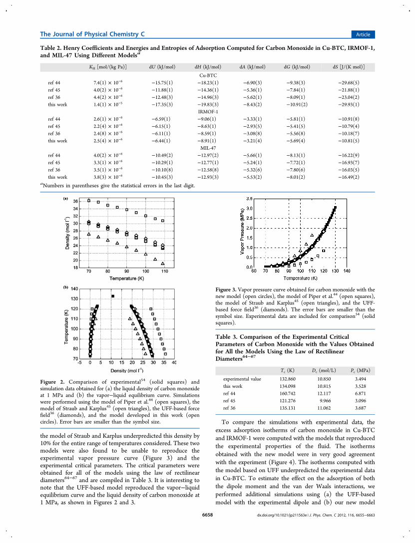
al.44 gave the highest values for the liquid density and thecritical temperature (Figure 2), leading to higher adsorptions inthe three structures. This model overpredicted the liquiddensity of carbon monoxide at 1 MPa by 15%. On the contrary,
Figure 1. Adsorption isotherms of carbon monoxide in (a) Cu-BTC,(b) IRMOF-1, and (c) MIL-47 at 298 K. The isotherms werecomputed using the model of Piper et al.44 (squares), the model ofStraub and Karplus45 (triangles), the UFF-based force field36
(diamonds), and the model developed in this work (circles). Theerror bars are smaller than the symbol size.
The Journal of Physical Chemistry C Article
dx.doi.org/10.1021/jp211563e | J. Phys. Chem. C 2012, 116, 6655−66636657
the model of Straub and Karplus underpredicted this density by10% for the entire range of temperatures considered. These twomodels were also found to be unable to reproduce theexperimental vapor pressure curve (Figure 3) and theexperimental critical parameters. The critical parameters wereobtained for all of the models using the law of rectilineardiameters64−67 and are compiled in Table 3. It is interesting tonote that the UFF-based model reproduced the vapor−liquidequilibrium curve and the liquid density of carbon monoxide at1 MPa, as shown in Figures 2 and 3.
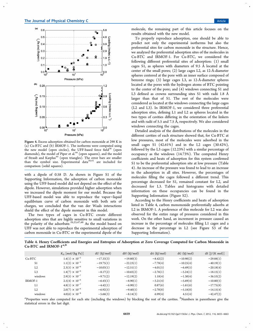
To compare the simulations with experimental data, theexcess adsorption isotherms of carbon monoxide in Cu-BTCand IRMOF-1 were computed with the models that reproducedthe experimental properties of the fluid. The isothermsobtained with the new model were in very good agreementwith the experiment (Figure 4). The isotherms computed withthe model based on UFF underpredicted the experimental datain Cu-BTC. To estimate the effect on the adsorption of boththe dipole moment and the van der Waals interactions, weperformed additional simulations using (a) the UFF-basedmodel with the experimental dipole and (b) our new model
Table 2. Henry Coefficients and Energies and Entropies of Adsorption Computed for Carbon Monoxide in Cu-BTC, IRMOF-1,and MIL-47 Using Different Modelsa
KH [mol/(kg Pa)] dU (kJ/mol) dH (kJ/mol) dA (kJ/mol) dG (kJ/mol) dS [J/(K mol)]
aNumbers in parentheses give the statistical errors in the last digit.
Figure 2. Comparison of experimental54 (solid squares) andsimulation data obtained for (a) the liquid density of carbon monoxideat 1 MPa and (b) the vapor−liquid equilibrium curve. Simulationswere performed using the model of Piper et al.44 (open squares), themodel of Straub and Karplus45 (open triangles), the UFF-based forcefield36 (diamonds), and the model developed in this work (opencircles). Error bars are smaller than the symbol size.
Figure 3. Vapor pressure curve obtained for carbon monoxide with thenew model (open circles), the model of Piper et al.44 (open squares),the model of Straub and Karplus45 (open triangles), and the UFF-based force field36 (diamonds). The error bars are smaller than thesymbol size. Experimental data are included for comparison54 (solidsquares).
Table 3. Comparison of the Experimental CriticalParameters of Carbon Monoxide with the Values Obtainedfor All the Models Using the Law of RectilinearDiameters64−67
dx.doi.org/10.1021/jp211563e | J. Phys. Chem. C 2012, 116, 6655−66636658
with a dipole of 0.58 D. As shown in Figure S1 of theSupporting Information, the adsorption of carbon monoxideusing the UFF-based model did not depend on the effect of thedipole. However, simulations provided higher adsorption whenwe increased the dipole moment for our model. Because theUFF-based model was able to reproduce the vapor−liquidequilibrium curve of carbon monoxide with both sets ofcharges, we concluded that the van der Waals interactionsshield the effect of the dipole moment in this model.The two types of cages in Cu-BTC create different
adsorption sites that are highly sensitive to small variations inthe polarity of the adsorbate.16,23,47,48 As the model based onUFF was not able to reproduce the experimental adsorption ofcarbon monoxide in Cu-BTC or the experimental dipole of the
molecule, the remaining part of this article focuses on theresults obtained with the new model.To properly reproduce adsorption, one should be able to
predict not only the experimental isotherms but also thepreferential sites for carbon monoxide in the structure. Hence,we analyzed the preferential adsorption sites of the molecules inCu-BTC and IRMOF-1. For Cu-BTC, we considered thefollowing different preferential sites of adsorption: (1) smallcages S1, as spheres with diameters of 9.5 Å located at thecenter of the small pores; (2) large cages L2, as 12-Å-diameterspheres centered at the pore with an inner surface composed ofbenzene rings; (3) large cages L3, as 12-Å-diameter sphereslocated at the pores with the hydrogen atoms of BTC pointingto the center of the pore; and (4) windows connecting S1 andL3 defined as crowns surrounding sites S1 with radii 1.8 Ålarger than that of S1. The rest of the molecules wereconsidered as located at the windows connecting the large cages(L2 and L3). In IRMOF-1, we considered three preferentialadsorption sites, defining L1 and L2 as spheres located in thetwo types of cavities differing in the orientation of the linkersand with radii of 5.5 and 7.5 Å, respectively. We also consideredwindows connecting the cages.Detailed analysis of the distributions of the molecules in the
different cavities of each structure showed that, for Cu-BTC atlow pressures, most of the molecules were adsorbed in thesmall cages S1 (42.61%) and in the L2 cages (30.42%),followed by the L3 cages (12.23%) with a similar percentage ofoccupancy as the windows (14.73%). The computed Henrycoefficients and heats of adsorption for this system confirmedS1 to be the preferential adsorption site at low pressure (Table4). An increase of the pressure was found to lead to an increasein the adsorption in all sites. However, the percentages ofmolecules filling the cages followed a different trend. Thispercentage decreased for S1, remained constant for L2, anddecreased for L3. Tables and histograms with detailedinformation on these occupancies can be found in theSupporting Information (Figure S2).According to the Henry coefficients and heats of adsorption
listed in Table 4, carbon mononoxide preferentially adsorbs atL2 in IRMOF-1. A preference of this molecule for L2 was alsoobserved for the entire range of pressures considered in thiswork. On the other hand, an increment in pressure caused anincrease in the percentage of molecules filling L1 cages and adecrease in the percentage in L2 (see Figure S3 of theSupporting Information).
Figure 4. Excess adsorption obtained for carbon monoxide at 298 K in(a) Cu-BTC and (b) IRMOF-1. The isotherms were computed usingthe new model (open circles), the UFF-based force field36 (opendiamonds), the model of Piper et al.44 (open squares), and the modelof Straub and Karplus44 (open triangles). The error bars are smallerthan the symbol size. Experimental data38,41 are included forcomparison (solid squares).
Table 4. Henry Coefficients and Energies and Entropies of Adsorption at Zero Coverage Computed for Carbon Monoxide inCu-BTC and IRMOF-1a,b
KH [mol/(kg Pa)] dU (kJ/mol) dH (kJ/mol) dA (kJ/mol) dG (kJ/mol) dS [J/(K mol)]
aProperties were also computed for each site (including the windows) by blocking the rest of the cavities. bNumbers in parentheses give thestatistical errors in the last digit.
The Journal of Physical Chemistry C Article
dx.doi.org/10.1021/jp211563e | J. Phys. Chem. C 2012, 116, 6655−66636659
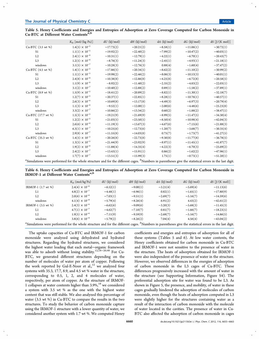
The uptake capacities of Cu-BTC and IRMOF-1 for carbonmonoxide were analyzed using dehydrated and hydratedstructures. Regarding the hydrated structures, we consideredthe highest water loading that each metal−organic frameworkwas able to adsorb without losing stability.12,18−20,48 For Cu-BTC, we generated different structures depending on thenumber of molecules of water per atom of copper. Followingthe work reported by Gul-E-Noor et al.,12 we analyzed foursystems with 35.3, 17.7, 8.9, and 4.5 wt % water in the structure,corresponding to 0.5, 1, 2, and 4 molecules of water,respectively, per atom of copper. As the structure of IRMOF-1 collapses at water contents higher than 3.9%,18 we considereda system with 3.5 wt % as the one with the highest watercontent that was still stable. We also analyzed this percentage ofwater (3.5 wt %) in Cu-BTC to compare the results in the twostructures. To study the behavior of carbon monoxide captureusing the IRMOF-1 structure with a lower quantity of water, weconsidered another system with 1.7 wt %. We computed Henry
coefficients and energies and entropies of adsorption for all ofthese systems (Tables 5 and 6). At low water contents, theHenry coefficients obtained for carbon monoxide in Cu-BTCand IRMOF-1 were not sensitive to the presence of water inthe structure. The heats of adsorption obtained for IRMOF-1were also independent of the presence of water in the structure.However, we observed differences in the energies of adsorptionof carbon monoxide in the L3 cages of Cu-BTC. Thesedifferences progressively increased with the amount of water inthe structure (see Supporting Information, Figure S4). Thepreferential adsorption site for water was found to be L3. Asshown in Figure 5, the presence, and mobility, of water in thesecages gradually hindered the adsorption of molecules of carbonmonoxide, even though the heats of adsorption computed in L3were slightly higher for the structures containing water as aresult of the interaction of carbon monoxide with the moleculeof water located in the cavities. The presence of water in Cu-BTC also affected the adsorption of carbon monoxide in cages
Table 5. Henry Coefficients and Energies and Entropies of Adsorption at Zero Coverage Computed for Carbon Monoxide inCu-BTC at Different Water Contentsa,b
KH [mol/(kg Pa)] dU (kJ/mol) dH (kJ/mol) dA (kJ/mol) dG (kJ/mol) dS [J/(K mol)]
aSimulations were performed for the whole structure and for the different cages. bNumbers in parentheses give the statistical errors in the last digit.
Table 6. Henry Coefficients and Energies and Entropies of Adsorption at Zero Coverage Computed for Carbon Monoxide inIRMOF-1 at Different Water Contentsa,b
KH (mol/kg/Pa) dU (kJ/mol) dH (kJ/mol) dA (kJ/mol) dG (kJ/mol) dS [J/(K mol)]
aSimulations were performed for the whole structure and for the different cages. bNumbers in parentheses give the statistical errors in the last digit.
The Journal of Physical Chemistry C Article
dx.doi.org/10.1021/jp211563e | J. Phys. Chem. C 2012, 116, 6655−66636660
S1 and L2, although to a lower extent. At a fixed value ofpressure, low contents of water appeared to to favor adsorptionin S1. This is because the molecules of water, preferentiallyadsorbed in L3, displaced the molecules of carbon monoxide tothe small cages. An additional increase of the water contentsfirst induced the presence of some traces of water in S1 and L2(10−20 wt %) and then caused the displacement of all of themolecules to L3, forming clusters (20−35 wt %). It is for thisreason that the adsorption of carbon monoxide decreased atmedium water contents, increasing again for structures withlarger water contents (see Supporting Information, Table S3).In IRMOF-1, both water and carbon monoxide were found
to be preferentially adsorbed in cavity L2. This is the larger ofthe two types of cavities in the structure and has the metalcenters more exposed than in L1 (Figure 6). Because of this
distribution, the interactions of molecules of water and carbonmonoxide with the metal atoms of the framework are strongerin this cage. As the water content in IRMOF-1 was low (up to3.5 wt %), the adsorption of carbon monoxide in the structurewas not found to be influenced by the molecules of water (seeFigures S5 and S6 and Table S4 of the SupportingInformation).
4. CONCLUSIONS
This work points out the differences in the adsorption ofcarbon monoxide by hydrated and dehydrated metal−organicframeworks. For the correct analysis of these differences, anaccurate and realistic model for carbon monoxide is needed.We have developed a model that reproduces the experimentaldipole moment and bulk properties of the molecule such as the
Figure 5. Carbon monoxide adsorbed in the S1 (top), L2 (bottom left), and L3 (bottom right) cages of Cu-BTC as a function of pressure and watercontent. The values of the maxima have been normalized to 1.
Figure 6. View of the metallic centers of IRMOF-1 from the inside of cages L1 (left) and L2 (right). The different atoms from the figure are carbon(blue), oxygen (red), hydrogen (white), and zinc (gray).
The Journal of Physical Chemistry C Article
dx.doi.org/10.1021/jp211563e | J. Phys. Chem. C 2012, 116, 6655−66636661
vapor−liquid equilibrium curve, vapor pressures, and liquiddensities at 1 MPa. Using this model, we demonstrated that thepresence of water can be used to enhance or hinder theadsorption of carbon monoxide in the MOF structure. Thisseems especially important in structures formed by cages ofdifferent sizes and shapes. According to our results, it is possibleto combine the topology of the framework and the polarity ofthe adsorbed molecules to obtain higher loadings. Thesefindings could be further exploited to increase the efficiency ofcurrent adsorption and separation processes.
■ ASSOCIATED CONTENT
*S Supporting InformationLennard-Jones parameters and partial charges used for Cu-BTC, IRMOF-1, and MIL-47 (Tables S1 and S2). Distributionsof the amounts of molecules of carbon monoxide per unit celladsorbed in each site of Cu-BTC and IRMOF-1 (Tables S3 andS4, respectively). Influence of the dipole and the model ofadsorption of carbon monoxide (Figure S1). Percentages ofadsorption of carbon monoxide in the cavities of Cu-BTC andIRMOF-1 (Figures S2 and S3, respectively) at differentpressures. Adsorption isotherms of carbon monoxide in Cu-BTC and IRMOF-1 (Figures S4 and S5, respectively) atdifferent water contents of the structure. Distribution of carbonmonoxide in IRMOF-1 as a function of the pressure and thewater content in the structure (Figure S6). This material isavailable free of charge via the Internet at http://pubs.acs.org.
NotesThe authors declare no competing financial interest.
■ ACKNOWLEDGMENTSThis work was supported by the Spanish “Ministerio de Cienciae Innovacion” (CTQ2010-16077/BQU), the “Junta deAndalucia” (P07-FQM-02595), and the European ResearchCouncil through an ERC Staring Grant (ERC-StG′11 RASPA-project). A.M.-C. thanks the Spanish “Ministerio de Educacion”for her predoctoral fellowship.
■ REFERENCES(1) Rowsell, J. L. C.; Yaghi, O. M. Microporous Mesoporous Mater.2004, 73, 3.(2) Li, J. R.; Kuppler, R. J.; Zhou, H. C. Chem. Soc. Rev. 2009, 38,1477.(3) Czaja, A. U.; Trukhan, N.; Muller, U. Chem. Soc. Rev. 2009, 38,1284.(4) Chui, S. S. Y.; Lo, S. M. F.; Charmant, J. P. H; Orpen, A. G.;Williams, I. D. Science 1999, 283, 1148.(5) Getzschmann, J.; Senkovska, I.; Wallacher, D.; Tovar, M.; Fairen-Jimenez, D.; Duren, T.; van Baten, J. M.; Krishna, R.; Kaskel, S.Microporous Mesoporous Mater. 2010, 136, 50.(6) Eddaoudi, M.; Kim, J.; Rosi, N.; Vodak, D.; Wachter, J.; O’Keeffe,M.; Yaghi, O. M. Science 2002, 295, 469.(7) Li, H.; Eddaoudi, M.; O’Keeffe, M.; Yaghi, O. M. Nature 1999,402, 276.(8) Li, Y. W.; Yang, R. T. AIChE J. 2008, 54, 269.(9) Liang, Z. J.; Marshall, M.; Chaffee, A. L. Greenhouse Gas ControlTechnol. 2009, 1 (9), 1265.(10) Liu, J.; Wang, Y.; Benin, A. I.; Jakubczak, P.; Willis, R. R.; LeVan,M. D. Langmuir 2010, 26, 14301.
(11) Henninger, S. K.; Schmidt, F. P.; Henning, H. M. Appl. Therm.Eng. 2010, 30, 11.(12) Gul-E-Noor, F.; Jee, B.; Poppl, A.; Hartman, M. R.; Himsl, D.;Bertmer, M. Phys. Chem. Chem. Phys. 2011, 13, 7783.(13) Kusgens, P.; Rose, M.; Senkovska, I.; Frode, H.; Henschel, A.;Siegle, S.; Kaskel, S. Microporous Mesoporous Mater. 2009, 120, 325.(14) Grajciar, L.; Bludsky, O.; Nachtigall, P. J. Phys. Chem. Lett. 2010,1, 3354.(15) Prestipino, C.; Regli, L.; Vitillo, J. G.; Bonino, F.; Damin, A.;Lamberti, C.; Zecchina, A.; Solari, P. L.; Kongshaug, K. O.; Bordiga, S.Chem. Mater. 2006, 18, 1337.(16) Castillo, J. M.; Vlugt, T. J. H.; Calero, S. J. Phys. Chem. C 2008,112, 15934.(17) Huang, L. M.; Wang, H. T.; Chen, J. X.; Wang, Z. B.; Sun, J. Y.;Zhao, D. Y.; Yan, Y. S. Microporous Mesoporous Mater. 2003, 58, 105.(18) Greathouse, J. A.; Allendorf, M. D. J. Am. Chem. Soc. 2006, 128,13312.(19) Bellarosa, L.; Calero, S.; Lopez, N., manuscript submitted.(20) Bellarosa, L.; Castillo-Sanchez, J. M.; Vlugt, T. J. H.; Calero, S.;Lopez, N., manuscript submitted.(21) Krishna, R.; van Baten, J. A. Langmuir 2010, 26, 3981.(22) Yazaydin, A. O.; Snurr, R. Q.; Park, T. H.; Koh, K.; Liu, J.;LeVan, M. D.; Benin, A. I.; Jakubczak, P.; Lanuza, M.; Galloway, D. B.;Low, J. J.; Willis, R. R. J. Am. Chem. Soc. 2009, 131, 18198.(23) Martin-Calvo, A.; Garcia-Perez, E.; Castillo, J. M.; Calero, S.Phys. Chem. Chem. Phys. 2008, 10, 7085.(24) Yazaydin, A. O.; Benin, A. I.; Faheem, S. A.; Jakubczak, P.; Low,J. J.; Willis, R. R.; Snurr, R. Q. Chem. Mater. 2009, 21, 1425.(25) Millward, A. R.; Yaghi, O. M. J. Am. Chem. Soc. 2005, 127,17998.(26) Yang, Q. Y.; Zhong, C. L.; Chen, J. F. J. Phys. Chem. C 2008,112, 1562.(27) Babarao, R.; Hu, Z. Q.; Jiang, J. W.; Chempath, S.; Sandler, S. I.Langmuir 2007, 23, 659.(28) Babarao, R.; Jiang, J. W.; Sandler, S. I. Langmuir 2009, 25, 5239.(29) Keskin, S.; Sholl, D. S. J. Phys. Chem. C 2007, 111, 14055.(30) Alaerts, L.; Seguin, E.; Poelman, H.; Thibault-Starzyk, F.; Jacobs,P. A.; De Vos, D. E. Chem.Eur. J. 2006, 12, 7353.(31) Walton, K. S.; Millward, A. R.; Dubbeldam, D.; Frost, H.; Low,J. J.; Yaghi, O. M.; Snurr, R. Q. J. Am. Chem. Soc. 2008, 130, 406.(32) Yang, Q. Y.; Zhong, C. L. J. Phys. Chem. B 2006, 110, 17776.(33) Liu, J. C.; Culp, J. T.; Natesakhawat, S.; Bockrath, B. C.; Zande,B.; Sankar, S. G.; Garberoglio, G.; Johnson, J. K. J. Phys. Chem. C 2007,111, 9305.(34) Britt, D.; Tranchemontagne, D.; Yaghi, O. M. Proc. Natl. Acad.Sci. U.S.A. 2008, 105, 11623.(35) Deng, H. X.; Doonan, C. J.; Furukawa, H.; Ferreira, R. B.;Towne, J.; Knobler, C. B.; Wang, B.; Yaghi, O. M. Science 2010, 327,846.(36) Sirjoosingh, A.; Alavi, S.; Woo, T. K. J. Phys. Chem. C 2010, 114,2171.(37) Valenzano, L.; Civalleri, B.; Chavan, S.; Palomino, G. T.; Arean,C.; Bordiga, S. J. Phys. Chem. C 2010, 114, 11185.(38) Wang, Q. M.; Shen, D. M.; Bulow, M.; Lau, M. L.; Deng, S. G.;Fitch, F. R.; Lemcoff, N. O.; Semanscin, J. Microporous MesoporousMater. 2002, 55, 217.(39) Karra, J. R.; Walton, K. S. Langmuir 2008, 24, 8620.(40) Wang, S.; Yang, Q. Y.; Zhong, C. L. Sep. Purif. Technol. 2008, 60,30.(41) Saha, D.; Deng, S. G. J. Chem. Eng. Data 2009, 54, 2245.(42) Karra, J. R.; Walton, K. S. J. Phys. Chem. C 2010, 114, 15735.(43) Xu, Q.; Zhong, C. L. J. Phys. Chem. C 2010, 114, 5035.(44) Piper, J.; Morrison, J. A.; Peters, C. Mol. Phys. 1984, 53, 1463.(45) Straub, J. E.; Karplus, M. Chem. Phys. 1991, 158, 221.(46) Garcia-Sanchez, A.; Ania, C. O.; Parra, J. B.; Dubbeldam, D.;Vlugt, T. J. H.; Krishna, R.; Calero, S. J. Phys. Chem. C 2009, 113,8814.(47) Calero, S.; Martin-Calvo, A.; Hamad, S.; Garcia-Perez, E. Chem.Commun. 2011, 47, 508.
The Journal of Physical Chemistry C Article
dx.doi.org/10.1021/jp211563e | J. Phys. Chem. C 2012, 116, 6655−66636662
(48) Martin-Calvo, A.; Garcia-Perez, E.; Garcia-Sanchez, A.; Bueno-Perez, R.; Hamad, S.; Calero, S. Phys. Chem. Chem. Phys. 2011, 13,11165.(49) Garcia-Perez, E.; Gascon, J.; Morales-Florez, V.; Castillo, J. M.;Kapteijn, F.; Calero, S. Langmuir 2009, 25, 1725.(50) Calero, S.; Dubbeldam, D.; Krishna, R.; Smit, B.; Vlugt, T. J. H.;Denayer, J. F. M.; Martens, J. A.; Maesen, T. L. M. J. Am. Chem. Soc.2004, 126, 11377.(51) Dubbeldam, D.; Calero, S.; Vlugt, T. J. H.; Krishna, R.; Maesen,T. L. M.; Smit, B. J. Phys. Chem. B 2004, 108, 12301.(52) Rappe, A. K.; Casewit, C. J.; Colwell, K. S.; Goddard, W. A. III;Skiff, W. M. J. Am. Chem. Soc. 1992, 114, 10024.(53) Burrus, C. A. J. Chem. Phys. 1959, 31, 1270.(54) NIST Chemistry WebBook; NIST Standard Reference Database69; National Institute of Standards and Technology (NIST):Gaithersburg, MD, 2005; available at http://webbook.nist.gov/chemistry/.(55) Rick, S. W. J. Chem. Phys. 2004, 120, 6085.(56) Mayo, S. L.; Olafson, B. D.; Goddard, W. A. III. J. Phys. Chem.1990, 94, 8897.(57) Frost, H.; Snurr, R. Q. J. Phys. Chem. C 2007, 111, 18794.(58) Duren, T.; Sarkisov, L.; Yaghi, O. M.; Snurr, R. Q. Langmuir2004, 20, 2683.(59) Myers, A. L.; Monson, P. A. Langmuir 2002, 18, 10261.(60) Barthelet, K.; Marrot, J.; Riou, D.; Ferey, G. Angew. Chem., Int.Ed. 2001, 41, 281.(61) Alaerts, L.; Kirschhock, C.; Maes, M.; van der Veen, M.; Finsy,V.; Depla, A.; Martens, J.; Baron, G.; Jacobs, P.; Denayer, J.; De Vos,D. Angew. Chem., Int. Ed. 2007, 46, 4293.(62) Bueno-Perez, R.; Garcia-Perez, E.; Gutierrez-Sevillano, J. J.;Merkling, P. J.; Calero, S. Adsorption Sci. Technol. 2010, 28, 823.(63) Castillo, J. M.; Vlugt, T. J. H.; Calero, S. J. Phys. Chem. C 2009,113, 20869.(64) Martin, M. G.; Siepmann, J. I. J. Phys. Chem. B 1998, 102, 2569.(65) Rowlinson, J. S.; Widom, B. Molecular Theory of Capillarity;Oxford University Press: New York, 1989.(66) Rowlinson, J. S.; Swinton, F. L. Liquids and Liquid Mixtures;Butterworths: London, 1982.(67) Atkins, P. W. Physical Chemistry; Oxford Higher Education:New York, 1990.
The Journal of Physical Chemistry C Article
dx.doi.org/10.1021/jp211563e | J. Phys. Chem. C 2012, 116, 6655−66636663