6


IFC08-001
Understanding emulsified water filtration from diesel fuels
Chuanfang Yang Stephen Larsen
Steve Wagner
Donaldson Company, Inc
ABSTRACT
Emulsified water filtration becomes more difficult when diesel fuel’s surfactancy is high, especially for additized ultralow sulfur diesel fuel (ULSD). The increased surfactancy can be reflected by the decreased fuel/water interfacial tension (IFT) and the lowered microseparometer rating (MSEP), which in turn result in the increased stability of water-in-fuel emulsion. It was found in our research with IFT ranging from 7 mN/m to 40 mN/m, MSEP from 0 to 100, that the lower the IFT and the MSEP, the smaller the water droplet size, and the more difficult the filtration even with composite coalescing materials. Coalescers made of glass and silicone impregnated cellulose are proven to be more effective than the traditional cellulose having water repellency. However, with careful material engineering, it’s possible to filter emulsified water with over 95% efficiency even at very low IFT and conventional fuel flow rate. It was also confirmed that media face velocity significantly affects the filtration efficiency, particularly when the IFT is low. Based on our findings, we think a test standard with specified fuel properties such as IFT and MSEP, and standardized media face velocities, be considered.
INTRODUCTION
As ultralow sulfur diesel (ULSD, S<15 ppm) is replacing the regular low sulfur (S<500 ppm) diesel for on and off-road vehicles powered by diesel engines, there is an urgent need to develop an effective fuel/water separator to remove water from the fuels. The detrimental effects of coarse and/or emulsified water have been well documented in literature and SAE test standards SAE J 1488 and J1839. Coarse water removal from fuels does not normally present technical difficulties, but emulsified water does. It is believed that traditional media on the market are not capable of achieving emulsified water/fuel separation efficiency of 95% in ULSD due to the low fuel/water interfacial tension (IFT). The problem is attributed to the change in fuel chemistry due to fuel additization. ULSD is blended with more synthetic lubricant additives than current fuel in order to keep the fuel lubricity normal. The lack of lubricity is due to the loss of the natural lubricants in the refinery fuel desulphurization process to meet the EU4 and US07 emission requirement. The effect of synthetic lubricant additives has several implications of which three are reviewed below. First, it increases the surfactancy of the fuel. Second, it
reduces the IFT of the water and fuel in many cases; and third, it reduces the water droplet size in fuel. As a whole, it makes water/fuel emulsion more stable for phase separation to occur. This is reflected in the disarming of a fuel/water separator, whether it being a stripper or a coalescer. Other additives in fuel could also disarm fuel/water separators, for example, the detergent additives used to prevent fuel injector fouling, and some of the surfactant-contained cetane improvers. The mechanisms of filter disarming by surfactants are not well understood. There are conflicting views; some people attribute it to surfactant adsorption on the filter media, and others argue the increased emulsion film stability is the cause. Donaldson Company has built extensive infrastructure to understand the fundamentals of fuel/water separation, and conducted numerous tests per modified SAE J1488 standard, in which the IFT was controlled well below 15 mN/m. Following are some highlights of our discoveries and in-depth understanding.
UNDERSTANDING THE TEST STANDARDS Currently there are three test standards and an ISO/TS to follow for fuel/water filtration test. For coarse water, the droplet size is defined as 180-260 um in SAE J1839. Water is injected after the fuel transfer pump without experiencing intensive mechanical shear. Droplets this large can be easily separated by a water repellent medium. For ISO/TS 16332, the same thing would occur for coarse water with a median size of 300 um. Note that the IFT is 10-15 mN/m lower, which could indicate that the agglomeration or coalescing of water droplets might be more difficult. The initial larger droplet size (300 um vs. 180-260 um) can cancel this interfacial tension effect. Note also that the fuel pump type is not specified purposely due to the fact that the pumps do not really contribute to the generation of the large water droplets. It is worth mentioning here that the use of the SAE standard is entirely voluntary, as indicated on the cover page of the standard. That gives room to the individuals to apply the standard in a better or worse way to characterize their filters based on their own understanding of the problem. The fundamental difference between SAE and ISO is beyond the scope of this paper’s review on the topic of emulsified water separation.
Southwest Research 8th International Filtration Conference
1
For emulsified water separation test, SAE J1488 is not really comparable with ISO 4020 because of the undefined water droplet size. ISO 4020 is typically used for low fuel flow tests, while SAE J1488 can be used for a maximal fuel flow rate up to 100 L/min. The key differentiating factors are the fuel pump applied and the test water concentration. For SAE J1488, centrifugal pump with strong mechanical shear (3500rpm) and 0.25% water concentration are recommended, so the water droplet generated is supposed to be much finer and better dispersed in fuel. On the contrary, ISO 4020 recommends a low shear diaphragm pump with 2% water injection, so the droplet formed should be much larger and a significant droplet agglomeration is expected due to the higher water concentration. The implication of these differences is that the SAE J1488 can be a more stringent test standard as opposed to ISO 4020. As a result, a filter passing the ISO test may not pass the SAE test even when the water concentration of the ISO is 7 times higher. This has to do with the emulsion stability and the fuel flow rate which will be discussed in the next sections. The ISO/TS 16332 is targeted at tests using fuels with low IFT (15 mN/m). There are options for choosing the inject water concentration from 1500 ppm to 2%. The water droplet is generated through an orifice installed after the fuel pump, with a suggested median droplet size of 60 um. This has not become an ISO test standard yet, but it does shed some light on how the test should be conducted for the future diesel fuels including ULSD and biodiesel, whose surfactancy can be much higher. We believe that by lowering the IFT of SAE J1488 from 25-30 mN/m to below 15 mN/m can allow us to do a stricter test for emulsified water separation. However, we must measure the mean or median droplet size to confirm our hypothesis. We anticipate the size to be much smaller than 60 um because of the strong mechanical shear generated by the centrifugal pump. We also expect the water-in-fuel emulsion formed in ULSD is more stable than in regular low sulfur diesel fuel due to the increased surfactancy effect. In addition, we have found fuels from different suppliers with the same IFT will respond to filters similarly because the fuel additive packages used are different. And finally, we believe filter configuration could have significant effect on emulsified water filtration efficiency by manipulating media face velocity and fuel flow dynamics.
Southwest Research 8th International Filtration Conference
EMULSIFIED WATER DROPLET SIZE
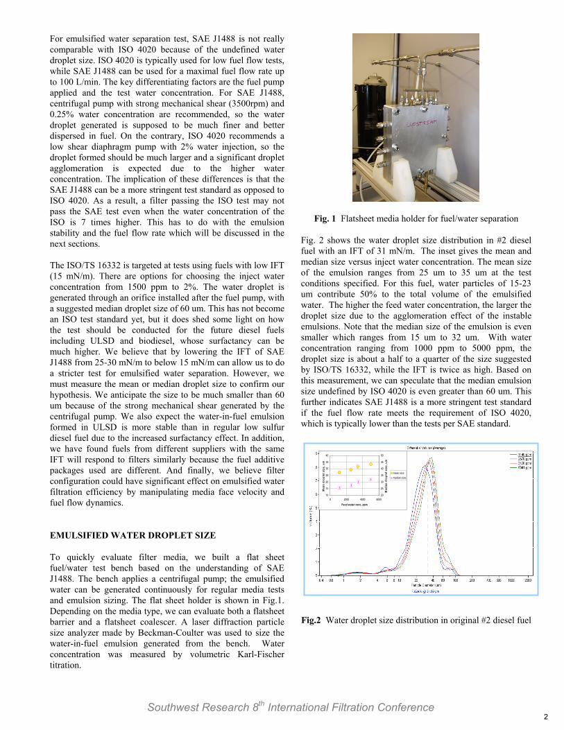
To quickly evaluate filter media, we built a flat sheet fuel/water test bench based on the understanding of SAE J1488. The bench applies a centrifugal pump; the emulsified water can be generated continuously for regular media tests and emulsion sizing. The flat sheet holder is shown in Fig.1. Depending on the media type, we can evaluate both a flatsheet barrier and a flatsheet coalescer. A laser diffraction particle size analyzer made by Beckman-Coulter was used to size the water-in-fuel emulsion generated from the bench. Water concentration was measured by volumetric Karl-Fischer titration.
Fig. 1 Flatsheet media holder for fuel/water separation
Fig. 2 shows the water droplet size distribution in #2 diesel fuel with an IFT of 31 mN/m. The inset gives the mean and median size versus inject water concentration. The mean size of the emulsion ranges from 25 um to 35 um at the test conditions specified. For this fuel, water particles of 15-23 um contribute 50% to the total volume of the emulsified water. The higher the feed water concentration, the larger the droplet size due to the agglomeration effect of the instable emulsions. Note that the median size of the emulsion is even smaller which ranges from 15 um to 32 um. With water concentration ranging from 1000 ppm to 5000 ppm, the droplet size is about a half to a quarter of the size suggested by ISO/TS 16332, while the IFT is twice as high. Based on this measurement, we can speculate that the median emulsion size undefined by ISO 4020 is even greater than 60 um. This further indicates SAE J1488 is a more stringent test standard if the fuel flow rate meets the requirement of ISO 4020, which is typically lower than the tests per SAE standard.
10
15
20
25
30
35
40
0 2000 4000 6000
Feed water conc, ppm
Mea
n dr
ople
t siz
e, u
m
20
25
30
35
40
45
50
Med
ian
drop
let s
ize,
um
mean sizemedian size
10
15
20
25
30
35
40
0 2000 4000 6000
Feed water conc, ppm
Mea
n dr
ople
t siz
e, u
m
20
25
30
35
40
45
50
Med
ian
drop
let s
ize,
um
mean sizemedian size
Fig.2 Water droplet size distribution in original #2 diesel fuel
2

Water-in-fuel emulsion size is significantly affected by the fuel type of interest as shown in Fig.3. The major property of the fuels measured is the IFT. It varies from 8 mN/m to 38 mN/m depending on how the fuel is pretreated or where the fuel is obtained. The rule of thumb generally is; the higher the IFT, the larger the droplet size, the less stable the emulsion, the easier the filtration. The increasing stability of the emulsion is also reflected, although not obvious, by the fact that once the IFT is reduced the mean droplet size gradually stops changing versus fuel flow rate as shown by the bottom two lines in Fig.3.
Southwest Research 8th International Filtration Conference
ULSD presents a special case with the lowest IFT and the smallest droplet size. It indicates the emulsion formed in this fuel is the most stable, and the filtration of such an emulsion is therefore the most difficult.
Fig.3 Mean droplet size vs. fuel IFT and flow rate
Again, the mean droplet size is a strong but not linear function of fuel IFT as shown in Fig. 4. For example, the clay (Fuller’s earth) treated #2 diesel fuel gives more than twice the size as compared to ULSD, while its IFT is 4 times higher. One critical but indirect piece of evidence that can be deduced from the plot is the behavior of the emulsion stability. As feed water concentration increases, the droplet size also increases accordingly for the #2 diesel. However, this is not the case for the ULSD. No size change was observed because of the much greater emulsion stability which prevents the water droplets from coalescing. For the #2 diesel with a higher IFT, because the interface between fuel and water is less stable, higher feed water concentration simply means more droplet agglomeration opportunities for particles to grow in size. IFT EFFECT ON FUEL/WATER FILTRATION As discussed above and as demonstrated in Fig.5, the lower the IFT, the smaller the droplet size, the more stable the emulsion, the more difficult the separation,. The reason lies in
Fuel flow rate 0.4 L/min
0
10
20
30
40
50
60
0 1000 2000 3000 4000 5000 6000
Inject Water Concentration (ppm)
Mea
n D
ropl
et S
ize
(um
)
Original #2 diesel fuel, IFT 31.8 dynes/cm Clay Treated #2 diesel, IFT 38.0 dynes/cm
Additized #2 diesel, IFT 20.9 dynes/cm Original ULSD, IFT 8.4 dynes/cm
Fig.4 Mean droplet size as a function of fuel IFT and inject water concentration
Inject water concentration 2500 ppm
0
10
20
30
40
50
60
0.3 0.4 0.5 0.6 0.7 0.8 0.9
Fuel Flow Rate (L/min)
Mea
n D
ropl
et S
ize
(um
)
Original #2 diesel fuel, IFT 31.8 dynes/cm Clay Treated #2 diesel, IFT 38.0 dynes/cm
Additized #2 diesel, IFT 20.9 dynes/cm Original ULSD, IFT 8.4 dynes/cm
the role of surfactant and/or fuel surfactancy. The presence of surfactant minimizes the two phase (fuel/water) system’s energy by reducing their interfacial tension so that they can overcome phase separation to be better mixed. Smaller droplet size favors such mixing which leads to more system stability.
Fig.5 Filter efficiency drops as IFT decreases However, looking at IFT only can be very misleading since IFT does not necessarily tell the fuel surfactancy. Surfactancy is related directly to the surfactant type, the surfactant concentration, the synergistic effect of co-solvent or co-surfactant, and so on. The surfactancy was indirectly measured in each of our tests with microseparometry (MSEP) The MSEP rating ranges from 00 to 100. The smaller the value, the higher the fuel surfactancy, which makes emulsified water separation more difficult. A low IFT fuel can often be translated also as a low MSEP fuel, but not always. Depending on the fuel chemistry, especially the additive package, low IFT fuel could also represent high MSEP fuel. However, rarely the opposite is true. It is more helpful to monitor both fuel IFT and MSEP to predict a filter medium’s behavior for emulsified water separation in such a fuel.
3

EFFECT OF FACE VELOCITY AND WATER CONCENTRATION
Southwest Research 8th International Filtration Conference
We found that media face velocity has a significant effect on media filtration efficiency, especially for low IFT fuels as illustrated in Fig. 6. This figure represents an additized fuel with IFT of 23 mN/m; the MSEP measured is 65 on average. The amount of water fed to the media during the flatsheet test varied from 60 g to 330 g. Flow rate of 0.4 L/min corresponds to a typical fuel flow for a conventional fuel system in terms of media face velocity. The dramatic drop in efficiency at higher flow rates is an indication that for emulsified water filtration a large media surface area is required to reduce the face velocity in order to prevent water from passing through the media. We found the similar effect of inject water concentration on media’s fuel/water separation efficiency. The higher the concentration, the lower the efficiency for low IFT fuels. However, the efficiency is more sensitive to water concentration at higher fuel flow rates, similar to what is shown in Fig.6. We conclude that it is the product of the water concentration and the fuel flow rate, which is the challenge water flux that determines the filter’s performance, provided the fuel type is given. Based on this knowledge, a better filter design can be developed. Cautions must be taken though to choose a good quality fuel/water filter when high fuel flow is required. For fuels such as ULSD and biodiesel, if emulsified water needs to be handled, minimizing the media face velocity is critical as the water concentration can be unpredictable. In this circumstance, the filter configuration design is very important in order to pack more media in a limited volume.
0
20
40
60
80
100
0.2 0.4 0.6 0.8 1
Flow rate, L/min
Ave
rage
effi
cien
cy, %
amt fed 60 gamt fed 150 gamt fed 240 gamt fed 330 g
Fig. 6 Filter media efficiency as a function of fuel flow rate
FILTER ELEMENT CHARACTERIZATION IN DIFFERENT ULSD We have described the effect of IFT on filter media’s ability to remove emulsified water. We also claim that coarse water is less a concern regardless of IFT. In addition, we understand that IFT sometimes does not tell the whole story about a fuel’s surfactancy, which is indirectly rated by MSEP. To verify all these, we chose three ULSD from three major suppliers to characterize filter elements from different manufacturers for fuel/water filtration. The three fuels have different fuel/water
IFT and MSEP so we expect filters to perform differently in each of them. Table 1 shows the test results, the fuel flow rate of all the tests is 5.7 L/min.
As expected, all the filters show over 96% efficiency in Supplier X’s fuel due to the higher IFT and MSEP. Fuel from Supplier Z is the toughest for most media to handle. Fuel from Supplier Y ranks in the middle due to its medium MSEP rating. Note that the IFT of Supplier Y’s fuel is comparable with Supplier Z’s fuel. This again is the reason why we need to look at both IFT and MSEP for fuel characterization. DISCUSSION Three typical fuel/water filtration media are commercially available on the market, which include silicone treated cellulose, combination of glass and cellulose in either co-pleated form or separated stage form, and the combination of meltblowns and cellulose. All these media can be badly disarmed by surfactant-rich fuels so their separation efficiency on emulsified water can be a huge concern in an application. The challenge to media suppliers is therefore significant and urgent. Regarding test standards, the current
Tabl
e 1.
Em
ulsi
fied
wat
er fi
ltrat
ion
effic
ienc
y in
orig
inal
fuel
s per
SA
E J1
488
TW
A: T
ime
wei
ghte
d av
erag
e ef
ficie
ncy
ULS
D
Supp
lier
X
Y
Z
Fi
lter
ID
TWA
E%
ΔP
i ps
i ΔP
f ps
i TW
A
E%
ΔPi
psi
ΔPf
psi
TWA
E%
ΔP
i ps
i ΔP
f ps
i A
99
.4
0.08
0.
15
82.7
0.
07
0.22
29
.6
0.10
0.
27
B
98.0
0.
07
0.13
93
.1
0.07
0.
13
52.4
0.
09
0.28
C
96.8
0.
08
0.29
95
.5
0.07
0.
25
96.5
0.
09
0.22
D
99
.1
0.08
0.
21
70.2
0.
06
0.36
38
.6
0.09
0.
47
E /
/ /
/ 38
.6
0.36
0.
55
Fuel
pr
oper
ties
IFT=
28-3
2 m
N/m
M
SEP=
97-1
00
IFT=
8-13
mN
/m
MSE
P=72
-89
IFT=
7-14
mN
/m
MSE
P=0-
50
4

SAE J1488 is yet to be modified subject to the massive fuel change from low sulfur to ULSD and its blend with biodiesel. Because of the more obvious effect of media face velocity on a filter’s fuel/water filtration efficiency in low IFT fuels, it should be reasonable to report face velocity in addition to fuel flow rate in standard test. Meanwhile, the effect of solid particle contamination on a medium’s fuel/water separation performance needs to be fully addressed. One of the commonly accepted ideas to increase emulsified water filtration efficiency is to enhance a medium’s surface water repellency. This is true only to a certain limit as shown in Fig. 7. Comparing media M and N, N has a much high water contact angle, and its emulsified water separation efficiency is 99.3% in contrast to 84.2% for M. Note that this test was conducted in a clay-treated fuel whose IFT is well above 35 mN/m. In a fuel with low IFT, because of the increased emulsion stability, the water droplet is much smaller and what’s more, the droplet could deform and conform its shape to the flow channel and therefore escape the capture by the medium. Bearing the complexity of the problem in mind, it is recommended that a surfactant resistant medium be designed to remove over 95% emulsified water from fuels with IFT ranging from 10-15 mN/m.
CONCLUSIONS
1. The difficulty of emulsified water filtration is because the emulsion formed in highly additized fuel such as ULSD is more stable.
2. The reduction in water droplet size for fuels with low IFT and low MSEP is an indication of increased water-in-fuel emulsion stability.
3. SAE J1488 can be a more stringent test standard than ISO 4020 and ISO/TS 16332 for filter evaluation once the fuel/water IFT is reduced to below 15 mN/m.
4. The emulsified water filtration efficiency also depends on media face velocity and the challenge water concentration. This is especially the case for fuels of high surfactancy in light of low IFT and low MSEP.
5. A surfactant resistant medium should be designed to remove emulsified water in fuels highly saturated with surfactant.
6. We believe filter configuration innovation with the right selection of filter media will be the optimized choice for engine fuel filtration.
ACKNOWLEDGMENTS
Thanks go to Dan Larsen for polishing the article, Paul Kojetin and Gregory Ufken for proof-reading
CONTACT
Chuanfang Yang, Ph.D.
Corporate Technology
Donaldson Company, Inc
Fig.7 Water contact angle image on M (top) and N (bottom) N is a result of chemical treatment of M
Southwest Research 8th International Filtration Conference 5


