37
1 Understanding MPLS OAM capabilities to troubleshoot MPLS Networks Mukhtiar A. Shaikh ([email protected] ) Moiz Moizuddin ([email protected] )
| Date post: | 21-Apr-2018 |
| Category: |
Documents |
| Upload: | trinhquynh |
| View: | 228 times |
| Download: | 2 times |

1
Understanding MPLS OAM capabilities to troubleshoot MPLS Networks
Mukhtiar A. Shaikh ([email protected])Moiz Moizuddin ([email protected])

222
Agenda
• MPLS Overview• Existing Ping/Trace Capabilities • LSP Ping/Trace
–Theory of Operation–MPLS Echo Packet–Configuration and Troubleshooting Using LSP Ping/Trace
•LSP Ping•LSP Trace
–AToM VCCV• Summary

333
MPLS OAM Overview
IngressPE CECE
EgressPE
MPLS OAM
End-End OAMAttachment VC OAM’s Attachment VC OAM’s
PWE3 orVPN Label
LSP Created by LDP and/or RSVP-TE
• Converged network implies a wide range of applications and OAM needs
• IP Based ToolsA flexible set of toolsLSP Ping / Traceroute

444
Agenda
• MPLS Overview• Existing Ping/Trace Capabilities • LSP Ping/Trace
–Theory of Operation–MPLS Echo Packet–Configuration and Troubleshooting Using LSP Ping/Trace
•LSP Ping•LSP Trace
–AToM VCCV• Summary

555
IP Ping/Trace
• PING makes use of the Internet Control MessageProtocol (ICMP) protocol
• Ping message of 2 typestype=8: ICMP echo request messagestype=0: ICMP echo reply message
• Traceroute makes use of the Internet Control Message Protocol (ICMP) protocol and TTL field on the IP header
• Traceroute is sent in a UDP packet encapsulated on an IP packet
• TTL-field of an IP datagram is decremented by each hop
666
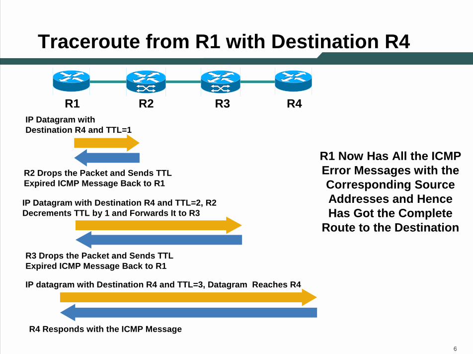
Traceroute from R1 with Destination R4
R1 R4R2 R3IP Datagram with Destination R4 and TTL=1
R2 Drops the Packet and Sends TTL Expired ICMP Message Back to R1
IP Datagram with Destination R4 and TTL=2, R2 Decrements TTL by 1 and Forwards It to R3
R3 Drops the Packet and Sends TTL Expired ICMP Message Back to R1
IP datagram with Destination R4 and TTL=3, Datagram Reaches R4
R4 Responds with the ICMP Message
R1 Now Has All the ICMP Error Messages with the Corresponding Source Addresses and Hence Has Got the Complete
Route to the Destination

777
Traceroute from R1 to R4 in MPLS Environment
R1 R4R2 R3
Label Used to Reach R4->67
Label Used to Reach R4->61
Label Used to Reach R1->22
Label Used to Reach R1->29
IP Packet’s TTL Field Is Copied onto the TTL Field of Label Header
MPLS Packet Destination R4 and TTL=1
Label Used to Reach R4->Pop
TTL=2

888
Agenda
• MPLS Overview• Existing Ping/Trace Capabilities • LSP Ping/Trace
–Theory of Operation–MPLS Echo Packet–Configuration and Troubleshooting Using LSP Ping/Trace
•LSP Ping•LSP Trace
–AToM VCCV• Summary

999
LSP Ping
• LSP Ping/Trace, like the traditional IP Ping, is based on echo request and echo reply
• LSP Ping/Trace doesn’t use an ICMP packet• Relies on IPv4(or IPv6) UDP packets with port 3503• UDP packets received with port 3503 are either an
MPLS echo or an MPLS echo-reply

101010
• We use the same label stack as used by the LSP and this makes the echo to be switched inband of LSP
• The IP header destination address field of the echo request is a 127/8 address
• An Echo reply, which may or not be labelled, has outgoing interface IP address as the source; destination IP address/port are copied from the echo-request’s source address/port
Theory of Operation
R3R1
MPLS Echo-req
49SA=Source AddrDA=Destination Addr
EchoEcho50 SASA DA=127/8
50
MPLS Echo-Reply
EchoEcho49 SASA DA=127/8
EchoEchoSASA DA=127/8LSP
R2R4Pos0/0Pos1/0

111111
Theory of Operation (Cont.)
• Various reasons for LSP to breakBroken LDP adjacencyMPLS not enabledMismatch labelsSoftware/hardware corruption
• Regular IP ping will be successful
R1
LSP Broken
4950
R3 R2R4
x

121212
Theory of Operation (Cont.)
• Presence of the 127/8 address in the IP header destination address field causes the packet to be consumed by any routers trying to forward the packet using the ip header
• In this case R2 would not forward the echo-req to R1 but rather consumes the packet and sends a reply to R3 accordingly
R3R1
LSP Broken
MPLS Echo-req
49SA=Source AddrDA=Destination Addr
EchoEcho50 SASA DA=127/8 EchoEchoSASA DA=127/8
50
R2R4
x

131313
Agenda
• MPLS Overview• Existing Ping/Trace Capabilities • LSP Ping/Trace
–Theory of Operation–MPLS Echo Packet–Configuration and Troubleshooting Using LSP Ping/Trace
•LSP Ping•LSP Trace
–AToM VCCV• Summary

141414
Packet Format of an MPLS LSP Echo
MPLS LSP Echo Request and Replies Are UDP Packets with Header and TLVs
TLVsTLVs
Timestamp Sent (NTP Seconds)Timestamp Sent (NTP Seconds)Timestamp Sent (NTP Fraction of usecs)Timestamp Sent (NTP Fraction of usecs)
Timestamp Received (NTP Seconds)Timestamp Received (NTP Seconds)
Timestamp Received (NTP Fraction of usecs)Timestamp Received (NTP Fraction of usecs)
Sequence Number Sender’s Handle
Message Type Reply ModeReply Mode Return Code Rtrn Subcode Rtrn Subcode Version Number Must Be Zero
IP/MPLS Header
Echo
Hea
der
Echo
Hea
der

151515
Packet Format of anMPLS LSP Echo (Cont.)
TLVsTLVs
Timestamp Sent (NTP Seconds)Timestamp Sent (NTP Seconds)Timestamp Sent (NTP Fraction of usecs)Timestamp Sent (NTP Fraction of usecs)
Timestamp Received (NTP Seconds)Timestamp Received (NTP Seconds)Timestamp Received (NTP Fraction of usecs)Timestamp Received (NTP Fraction of usecs)
Sequence Number Sender’s Handle
Reply ModeReply Mode Return Code Rtrn Subcode Rtrn Subcode Must Be Zero
IP/MPLS Header
Version Number: It’s Set to One Message Type: Message Type Field Tells Whether the Packet Is an MPLS Echo Request or MPLS Echo Reply
MPLS EchoReply2
MPLS Echo Request1
MeaningValueMessage Type
Version Number Version Number Version Number Message TypeMessage Type

161616
Packet Format of an MPLS LSP Echo (Cont.)
Reply Mode: The Reply Mode Is Used to Control How the Target Router Replies to MPLS Echo Request
TLVsTLVs
Timestamp Sent (NTP Seconds)Timestamp Sent (NTP Seconds)Timestamp Sent (NTP Fraction of usecs)Timestamp Sent (NTP Fraction of usecs)
Timestamp Received (NTP Seconds)Timestamp Received (NTP Seconds)Timestamp Received (NTP Fraction of usecs)Timestamp Received (NTP Fraction of usecs)
Sequence Number Sender’s Handle
Message Type Return Code Rtrn Subcode Rtrn Subcode Version Number Must Be Zero
IP/MPLS Header
Reply via an IPv4 UDP packet with Router Alert
3
Reply via an IPv4 UDP Packet2
Do Not Reply1
MeaningValueReply ModeReply Mode

171717
TLVsTLVs
Timestamp Sent (NTP Seconds)Timestamp Sent (NTP Seconds)Timestamp Sent (NTP Fraction of usecs)Timestamp Sent (NTP Fraction of usecs)
Timestamp Received (NTP Seconds)Timestamp Received (NTP Seconds)Timestamp Received (NTP Fraction of usecs)Timestamp Received (NTP Fraction of usecs)
Sequence Number Sender’s Handle
Message Type Reply ModeReply Mode Return Code Rtrn Subcode Rtrn Subcode Version Number Must Be Zero
IP/MPLS Header
Return Code
• The router initiating the LSP ping/trace would set the return code to zero
• The replying router would set it accordingly based on the table shown
Replying Router Has No Mapping for the FEC 4
Replying Router Is Not One of the "Downstream Routers"
5
Malformed Echo Request Received1
The Error Code Is Contained in the Error Code TLV0
Replying Router Is One of the "Downstream Routers", and Its Mapping for this FEC on the Received Interface Is the Given Label
6
Replying Router Is an Egress for the FEC3
One Or More of the TLVs Was Not Understood 2
MeaningValue
Return CodeReturn Code

181818
Target FEC Stack TLV
9
7
6
5
4
3
2
1
Sub Type
Reserved
RSVP IPv6 Session Query 56
RSVP IPv4 Session Query 20
LDP IPv6 Prefix17
VPN IPv6 prefix 25
VPN IPv4 Prefix 13
L2 Circuit ID 10
LDP IPv4 Prefix5
ValueFieldLength
181818
Pad3
Downstream Mapping2
Vendor Enterprise Code 5
Error Code4
Target FEC Stack1
MeaningValue

191919
Sub-TLVs
0x0001 Length = 5
Prefix Length
Ipv4 Prefix
15160 7 8
31
• LDP IPv4 Prefix Sub-tlv
0x0003 Length = 20 IPv4 Tunnel Endpoint Address
0 15 16 31
Must Be Zero Tunnel ID Extended Tunnel ID
Must Be Zero LSP ID IPv4 Tunnel Sender Address
• RSVP IPv4 Prefix Sub-tlv

202020
L2 Circuit Type (Sub-TLV)• L2 Circuit Type Sub-tlv
0x0009 Length = 16
PWID Type PWID Length=4
Remote PE Address
Source PE Address
PWID
• L3VPN (VPN IPv4 prefix) Sub-tlv

212121
Downstream Mapping TLV
R2 R3R1 E0/0 10.200.12.1
10.200.12.2 E0/1
10.200.23.3 E1/1
E1/0 10.200.23.210.200.0.2 10.200.0.310.200.0.1
R1’s Downstream Mapping for 10.200.0.3 Common_HeaderMTU: Mtu of E0/0Address Type 1Downstream Intf Addr 10.200.12.1Downstream Label 50
R2’s Downstream Mapping for 10.200.0.3 Common_HeaderMTU: Mtu of E1/0Address Type 1Downstream Intf Addr 10.200.23.2
Label 50
Pad3Downstream Mapping2
Vendor Enterprise Code 5Error Code4
Target FEC Stack1MeaningValue

222222
Agenda
• MPLS Overview• Existing Ping/Trace Capabilities • LSP Ping/Trace
–Theory of Operation–MPLS Echo Packet–Configuration and Troubleshooting Using LSP Ping/Trace
•LSP Ping•LSP Trace
–AToM VCCV• Summary

232323
R3#ping mpls ip 10.200.0.4/32Sending 5, 100-byte MPLS Echos to 10.200.0.4/32,
timeout is 2 seconds, send interval is 0 msec:
Codes: '!' - success, 'Q' - request not transmitted,'.' - timeout, 'U' - unreachable,'R' - downstream router but not target
Type escape sequence to abort.UUUUUSuccess rate is 0 percent (0/5)
Troubleshooting Using LSP Ping (IPv4)MPLS Disabled at the P Router (R1)
MPLS Disabled on R1R3
R4
R1 LSP Broken
R3#ping mpls ipv4 10.200.0.4/32 verboseSending 5, 100-byte MPLS Echos to 10.200.0.4/32,
timeout is 2 seconds, send interval is 0 msec:
Codes: '!' - success, 'Q' - request not transmitted,'.' - timeout, 'U' - unreachable,'R' - downstream router but not target
Type escape sequence to abort.U 10.200.21.1, return code 4U 10.200.21.1, return code 4U 10.200.21.1, return code 4U 10.200.21.1, return code 4U 10.200.21.1, return code 4
Success rate is 0 percent (0/5)
R2
• If a Regular Ping Is Done from R3 to R4, It Would Be Successful But an LSP Ping Would Fail
R3#ping 10.200.0.4!!!!!Success rate is 100 percent (5/5), round-trip min/avg/max = 24/28/32 ms
• The Response Would Come from R1

242424
R1R6
R5
R3R4
R2
Troubleshooting Using LSP Ping (IPv4)(Using Router Alert)
Echo-req Is Sent from R1-R6
R6 Issues an Echo-replyR5 Has a Wrong Label Binding and Forward the Packet to R4R3 Would Drop the PacketSo LSP Ping Fails
Send a ping from R1 with Router Alert reply mode option
R5 Receives a Reply with RA
It Process Switch the Packet Correctly to R2

252525
Troubleshooting Using LSP Ping (RSVP IPv4)
R1R3
Tunnel 1
Tunnel 2
R2
R4
LSP Ping Is Initiated from R1 through Tunnel 1
Due to an Error on R2 the LSP Ping Is Switched into Tun 2
R4 Would Recognize that dest addr, LSP id and Tu id Are Different and Would Reply with a Return Code 4
262626
Agenda
• MPLS Overview• Existing Ping/Trace Capabilities • LSP Ping/Trace
–Theory of Operation–MPLS Echo Packet–Configuration and Troubleshooting Using LSP Ping/Trace
•LSP Ping•LSP Trace
–AToM VCCV• Summary
272727
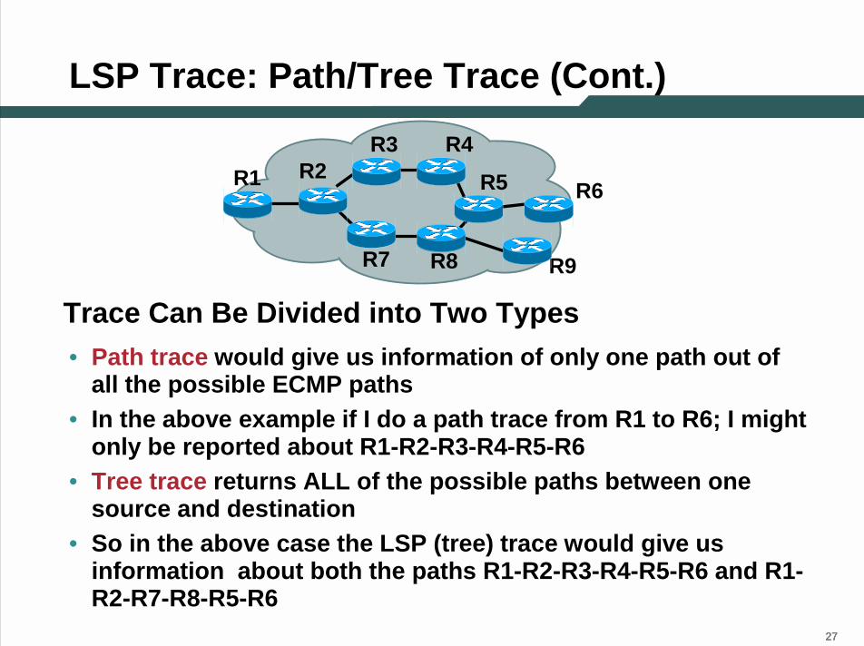
LSP Trace: Path/Tree Trace (Cont.)
• Path trace would give us information of only one path out of all the possible ECMP paths
• In the above example if I do a path trace from R1 to R6; I mightonly be reported about R1-R2-R3-R4-R5-R6
• Tree trace returns ALL of the possible paths between one source and destination
• So in the above case the LSP (tree) trace would give us information about both the paths R1-R2-R3-R4-R5-R6 and R1-R2-R7-R8-R5-R6
R1R3
R2
R7
R6R5R4
R8 R9
Trace Can Be Divided into Two Types

282828
Troubleshooting Using LSP Trace (IPv4)
• There is an intermittent response for the data traffic using theLSP R3-R4-R1-R2
• Sweeping LSP ping tells us that packets over 1500 are failing
R3R2
R1R4
Output with regular trace..
R3#tracer 10.200.0.2
Type escape sequence to abort.Tracing the route to 10.200.0.2
1 10.200.34.4 [MPLS: Label 44 Exp 0] 0 msec 0 msec 0 msec2 10.200.14.1 [MPLS: Label 22 Exp 0] 0 msec 0
msec 0 msec3 10.200.12.2 0 msec * 0 msec
R3#
But if an LSP trace is done, output looks as follows
R3#tracer mpls ip 10.200.0.2/32Tracing MPLS Label Switched Path to 10.200.0.2/32, timeout is 2 seconds
Codes: '!' - success, 'Q' - request not transmitted,'.' - timeout, 'U' - unreachable,'R' - downstream router but not target
Type escape sequence to abort.0 10.200.34.3 MRU 4470 [Labels: 44 Exp: 0]
R 1 10.200.14.4 MRU 1500 [Labels: 22 Exp: 0] 4 msR 2 10.200.12.1 MRU 4474 [implicit-null] 15 ms! 3 10.200.12.2 20 ms

292929
Troubleshooting UsingLSP Trace (RSVP IPv4)Customer Complains That He’s Seeing Latency; Customer Traffic Is Going Through Tunnel 1
Due to an Error on R2 the Customer Traffic Is Switched into Tunnel 2
LSP Ping from R1 Would Work as All the Five Values in the LSP Ping Would Be Correct
When We Do LSP Trace R5 Would Not Be Able to Match the 5 Tuples and Would Reply with a Return Code of 4
R1 R3
Tunnel 1
R2
R4
R5 Tunnel 2 (Longer/ Slower path)
R1#ping mpls traffic-eng tunnel tunnel1
R1#trace mpls traffic-eng tunnel tunnel1
303030
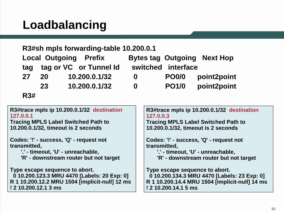
Loadbalancing
R3#trace mpls ip 10.200.0.1/32 destination 127.0.0.3Tracing MPLS Label Switched Path to 10.200.0.1/32, timeout is 2 seconds
Codes: '!' - success, 'Q' - request not transmitted,
'.' - timeout, 'U' - unreachable,'R' - downstream router but not target
Type escape sequence to abort.0 10.200.134.3 MRU 4470 [Labels: 23 Exp: 0]
R 1 10.200.14.4 MRU 1504 [implicit-null] 14 ms! 2 10.200.14.1 5 ms
R3#sh mpls forwarding-table 10.200.0.1Local Outgoing Prefix Bytes tag Outgoing Next Hoptag tag or VC or Tunnel Id switched interface27 20 10.200.0.1/32 0 PO0/0 point2point
23 10.200.0.1/32 0 PO1/0 point2pointR3#
R3#trace mpls ip 10.200.0.1/32 destination 127.0.0.1Tracing MPLS Label Switched Path to 10.200.0.1/32, timeout is 2 seconds
Codes: '!' - success, 'Q' - request not transmitted,
'.' - timeout, 'U' - unreachable,'R' - downstream router but not target
Type escape sequence to abort.0 10.200.123.3 MRU 4470 [Labels: 20 Exp: 0]
R 1 10.200.12.2 MRU 1504 [implicit-null] 12 ms! 2 10.200.12.1 3 ms

313131
Agenda
• MPLS Overview• Existing Ping/Trace Capabilities • LSP Ping/Trace
–Theory of Operation–MPLS Echo Packet–Configuration and Troubleshooting Using LSP Ping/Trace
•LSP Ping•LSP Trace
–AToM VCCV• Summary
323232
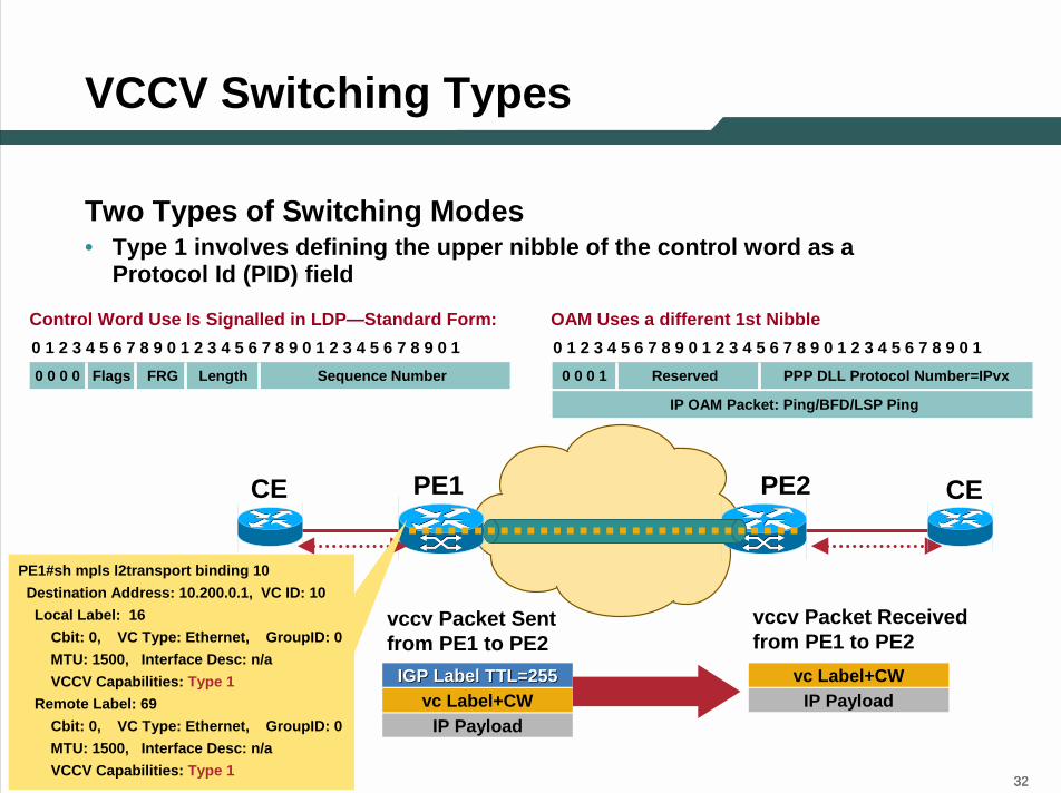
VCCV Switching Types
Two Types of Switching Modes• Type 1 involves defining the upper nibble of the control word as a
Protocol Id (PID) field
0 1 2 3 4 5 6 7 8 9 0 1 2 3 4 5 6 7 8 9 0 1 2 3 4 5 6 7 8 9 0 10 0 0 0 Flags FRG Length Sequence Number
OAM Uses a different 1st NibbleControl Word Use Is Signalled in LDP—Standard Form:0 1 2 3 4 5 6 7 8 9 0 1 2 3 4 5 6 7 8 9 0 1 2 3 4 5 6 7 8 9 0 1
0 0 0 1 Reserved PPP DLL Protocol Number=IPvx
IP OAM Packet: Ping/BFD/LSP Ping
PE2PE1CE CE
vccv Packet Sent from PE1 to PE2
vccv Packet Received from PE1 to PE2
vc Label+CWIP Payload
IGP Label TTL=255IGP Label TTL=255 vc Label+CWIP Payload
PE1#sh mpls l2transport binding 10Destination Address: 10.200.0.1, VC ID: 10Local Label: 16
Cbit: 0, VC Type: Ethernet, GroupID: 0MTU: 1500, Interface Desc: n/aVCCV Capabilities: Type 1
Remote Label: 69Cbit: 0, VC Type: Ethernet, GroupID: 0MTU: 1500, Interface Desc: n/aVCCV Capabilities: Type 1

333333
VCCV Switching Types (Cont.)
• Type 2 involves shimming a MPLS router alert label between the IGP label stack and VC label
PE2PE1CE CE
PE1#sh mpls l2transport binding 10Destination Address: 10.200.0.1, VC ID: 10Local Label: 16
Cbit: 0, VC Type: Ethernet, GroupID: 0MTU: 1500, Interface Desc: n/aVCCV Capabilities: Type 2
Remote Label: 69Cbit: 0, VC Type: Ethernet, GroupID: 0MTU: 1500, Interface Desc: n/aVCCV Capabilities: Type 2
vccv Packet Sent from PE1 to PE2
vccv Packet Received from PE1 to PE2
IP Payload
Rtr Alert Label 0x0001vc Label+CW
IGP Label TTL=255IGP Label TTL=255
IP Payload
Rtr Alert Label 0x0001vc Label+CW

343434
Troubleshooting Using LSP Ping (L2 CKT)
• Return code 4 sent due to some error condition either of the following has occurred
Wrong VC ID Wrong VC TypeWrong Source Address
R3
AToM Tunnel
MPLS Echo-req
R1#*Jan 19 19:32:17.726: LSPV: AToM echo request rx packet handler*Jan 19 19:32:17.726: LSPV: Echo packet received: src 10.200.0.3, dst 127.0.0.1, size 122*Jan 19 19:32:17.734: LSPV: Echo Hdr decode: version 1, msg type 1, reply mode 2 , return_code 0, return_subcode 0, sender handle 850000D1, sequence number 1, ti mestamp sent 20:22:30 UTC Mon Jan 19 2004, timestamp rcvd 00:00:00 UTC Mon Jan 1 1900*Jan 19 19:32:17.734: LSPV: tlvtype 1, tlvlength 20*Jan 19 19:32:17.734: LSPV: AToM FEC decode: srcaddr 10.200.0.1, destaddr 10.200 .0.3, vcid 10, vctype 5*Jan 19 19:32:17.734: LSPV: Target FEC stack length = 20, retcode = 3*Jan 19 19:32:17.734: LSPV: tlvtype 3, tlvlength 8*Jan 19 19:32:17.734: LSPV: Pad TLV decode: type 1, size 8*Jan 19 19:32:17.734: LSPV: Echo Hdr encode: version 1, msg type 2, reply mode 2 , return_code 4, return_subcode 0, sender handle 850000D1, sequence number 1, ti mestamp sent 20:22:30 UTC Mon Jan 19 2004, timestamp rcvd 19:32:17 UTC Mon Jan 1 9 2004
R1
MPLS Echo-reply with Return Code 4
R3#ping mpls pseudowire <IPv4 peer IP addr > <VC ID>?destination Destination address or address rangeexp EXP bits in mpls headerinterval Send interval between requests in Routercpad Pad TLV patternrepeat Repeat countreply Reply modesize Packet sizesource Source specified as an IP addresssweep Sweep range of sizestimeout Timeout in secondsttl Time to liveverbose verbose mode for ping output
Pinging from R3 to R1 through AToM TunnelR3#ping mpls pseudowire 10.200.0.1 10

353535
Agenda
• MPLS Overview• Existing Ping/Trace Capabilities • LSP Ping/Trace
–Theory of Operation–MPLS Echo Packet–Configuration and Troubleshooting Using LSP Ping/Trace
•LSP Ping•LSP Trace
–AToM VCCV• Summary

363636
Summary
• Traditional ping/trace not able to detect the problems in the MPLS networks.
• LSP ping/trace brings a new set of tools to troubleshoot MPLS forwarding plane problems
• VCCV adds new capability to help troubleshoot layer2 VPN issues

373737
THANK YOU


