RELAYSRelays are used throughout the automobile. Relays which come in assorted sizes, ratings,and applications, are used as remote control switches. A typical vehicle can have 20 relaysor more.
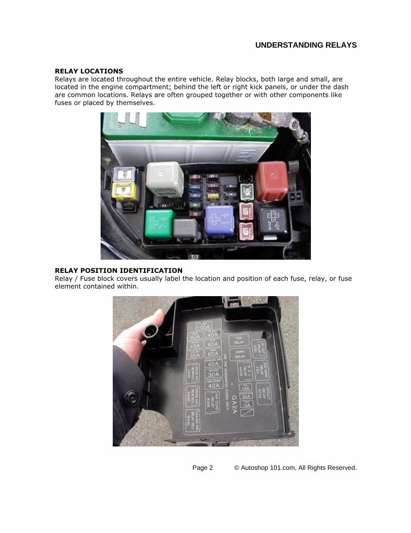
RELAY LOCATIONSRelays are located throughout the entire vehicle. Relay blocks, both large and small, arelocated in the engine compartment; behind the left or right kick panels, or under the dashare common locations. Relays are often grouped together or with other components likefuses or placed by themselves.
RELAY POSITION IDENTIFICATIONRelay / Fuse block covers usually label the location and position of each fuse, relay, or fuseelement contained within.
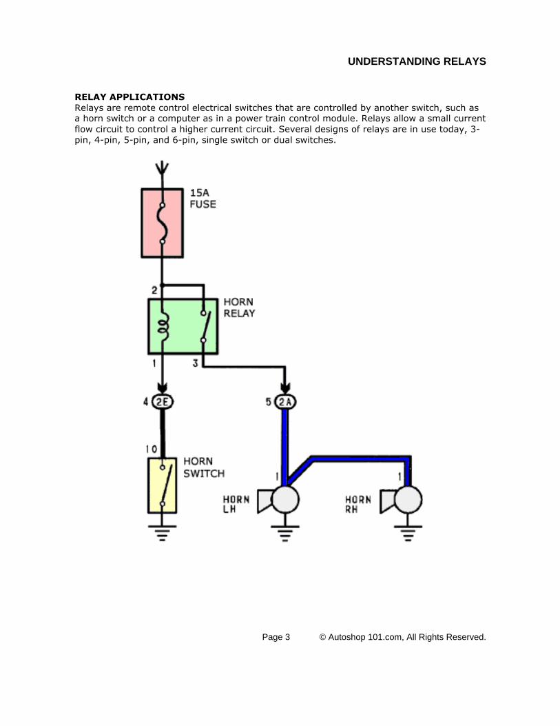
RELAY APPLICATIONSRelays are remote control electrical switches that are controlled by another switch, such asa horn switch or a computer as in a power train control module. Relays allow a small currentflow circuit to control a higher current circuit. Several designs of relays are in use today, 3-pin, 4-pin, 5-pin, and 6-pin, single switch or dual switches.
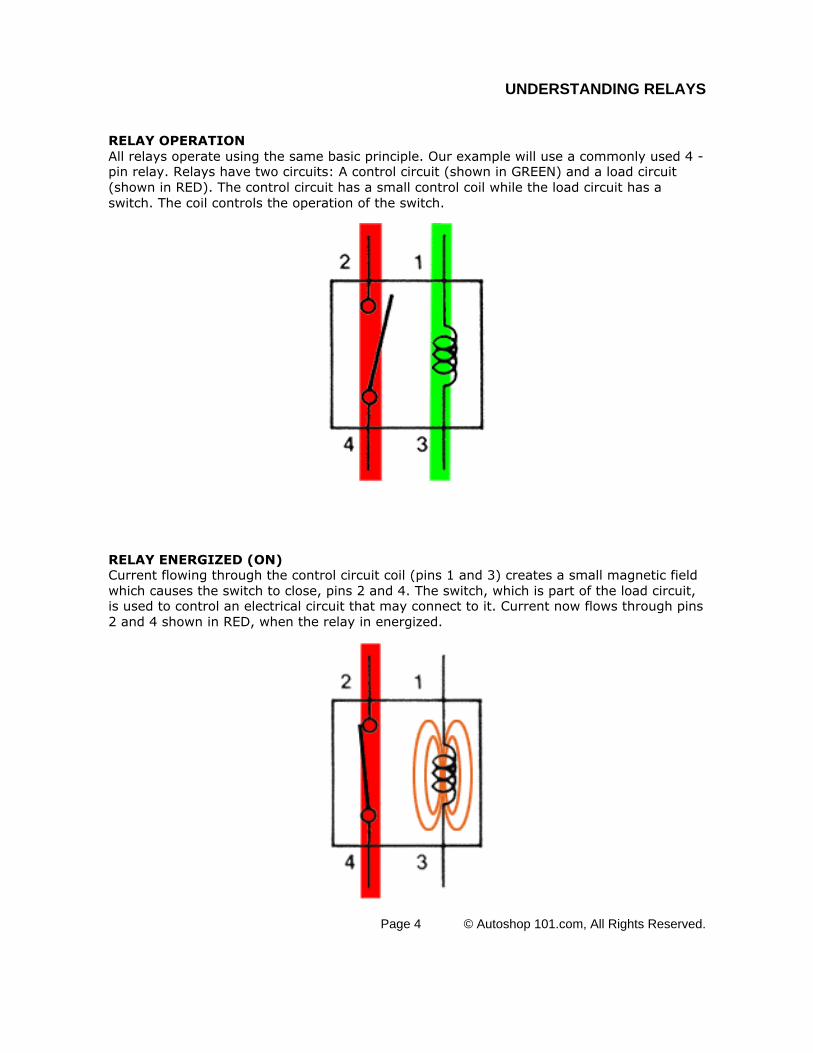
RELAY OPERATIONAll relays operate using the same basic principle. Our example will use a commonly used 4 -pin relay. Relays have two circuits: A control circuit (shown in GREEN) and a load circuit(shown in RED). The control circuit has a small control coil while the load circuit has aswitch. The coil controls the operation of the switch.
RELAY ENERGIZED (ON)Current flowing through the control circuit coil (pins 1 and 3) creates a small magnetic fieldwhich causes the switch to close, pins 2 and 4. The switch, which is part of the load circuit,is used to control an electrical circuit that may connect to it. Current now flows through pins2 and 4 shown in RED, when the relay in energized.
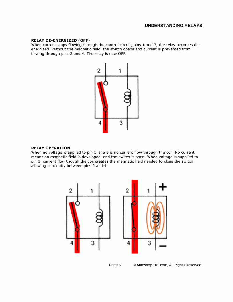
RELAY DE-ENERGIZED (OFF)When current stops flowing through the control circuit, pins 1 and 3, the relay becomes de-energized. Without the magnetic field, the switch opens and current is prevented fromflowing through pins 2 and 4. The relay is now OFF.
RELAY OPERATIONWhen no voltage is applied to pin 1, there is no current flow through the coil. No currentmeans no magnetic field is developed, and the switch is open. When voltage is supplied topin 1, current flow though the coil creates the magnetic field needed to close the switchallowing continuity between pins 2 and 4.
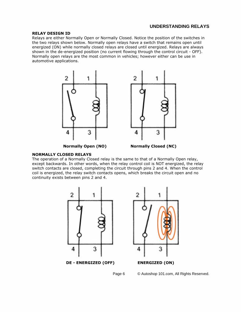
RELAY DESIGN IDRelays are either Normally Open or Normally Closed. Notice the position of the switches inthe two relays shown below. Normally open relays have a switch that remains open untilenergized (ON) while normally closed relays are closed until energized. Relays are alwaysshown in the de-energized position (no current flowing through the control circuit - OFF).Normally open relays are the most common in vehicles; however either can be use inautomotive applications.
Normally Open (NO) Normally Closed (NC)
NORMALLY CLOSED RELAYSThe operation of a Normally Closed relay is the same to that of a Normally Open relay,except backwards. In other words, when the relay control coil is NOT energized, the relayswitch contacts are closed, completing the circuit through pins 2 and 4. When the controlcoil is energized, the relay switch contacts opens, which breaks the circuit open and nocontinuity exists between pins 2 and 4.
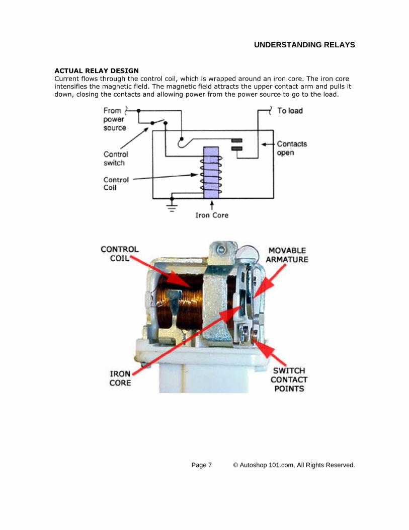
ACTUAL RELAY DESIGNCurrent flows through the control coil, which is wrapped around an iron core. The iron coreintensifies the magnetic field. The magnetic field attracts the upper contact arm and pulls itdown, closing the contacts and allowing power from the power source to go to the load.
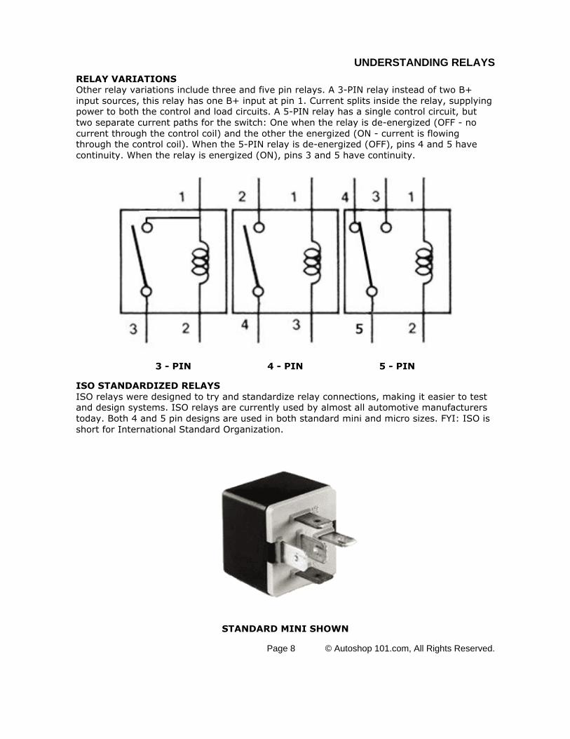
RELAY VARIATIONSOther relay variations include three and five pin relays. A 3-PIN relay instead of two B+input sources, this relay has one B+ input at pin 1. Current splits inside the relay, supplyingpower to both the control and load circuits. A 5-PIN relay has a single control circuit, buttwo separate current paths for the switch: One when the relay is de-energized (OFF - nocurrent through the control coil) and the other the energized (ON - current is flowingthrough the control coil). When the 5-PIN relay is de-energized (OFF), pins 4 and 5 havecontinuity. When the relay is energized (ON), pins 3 and 5 have continuity.
3 - PIN 4 - PIN 5 - PIN
ISO STANDARDIZED RELAYSISO relays were designed to try and standardize relay connections, making it easier to testand design systems. ISO relays are currently used by almost all automotive manufacturerstoday. Both 4 and 5 pin designs are used in both standard mini and micro sizes. FYI: ISO isshort for International Standard Organization.
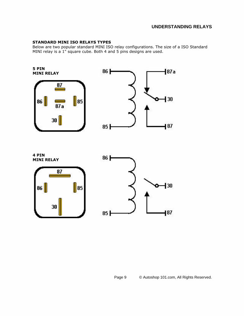
STANDARD MINI ISO RELAYS TYPESBelow are two popular standard MINI ISO relay configurations. The size of a ISO StandardMINI relay is a 1" square cube. Both 4 and 5 pins designs are used.
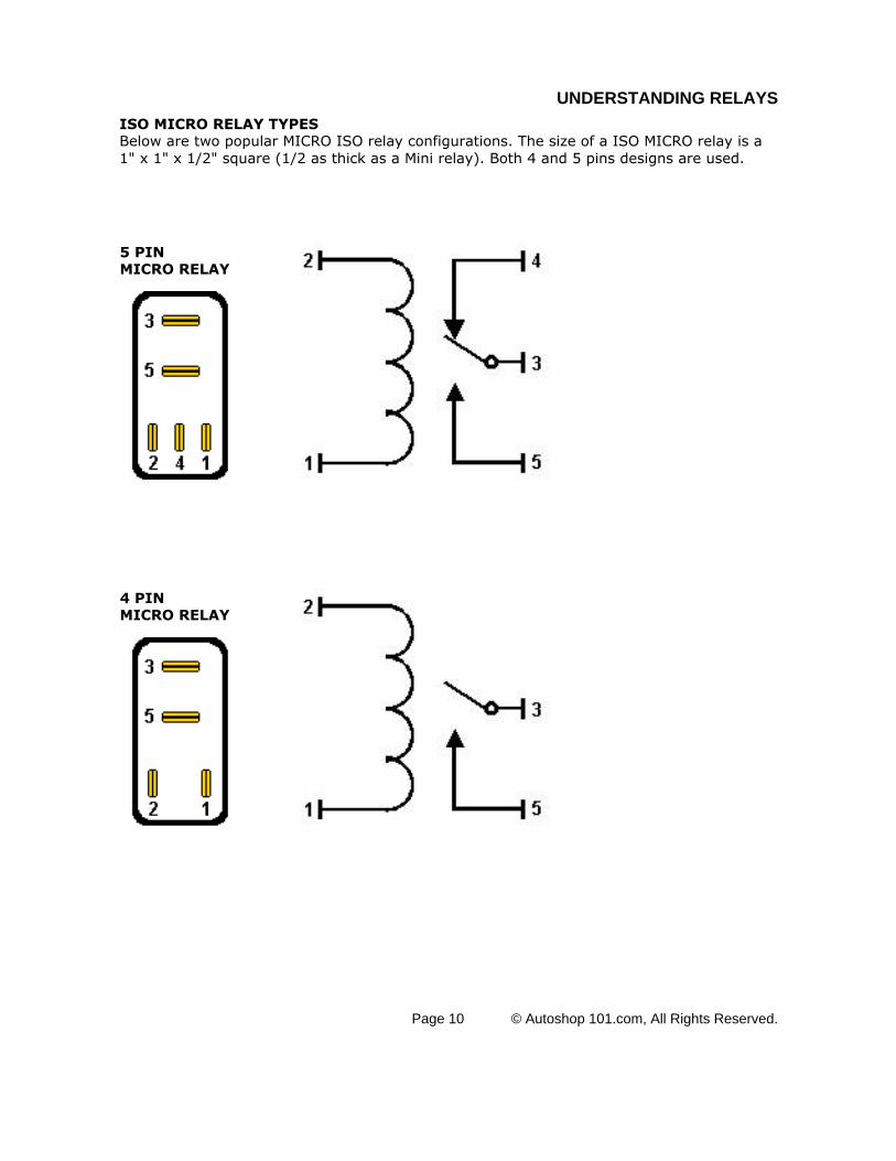
ISO MICRO RELAY TYPESBelow are two popular MICRO ISO relay configurations. The size of a ISO MICRO relay is a1" x 1" x 1/2" square (1/2 as thick as a Mini relay). Both 4 and 5 pins designs are used.
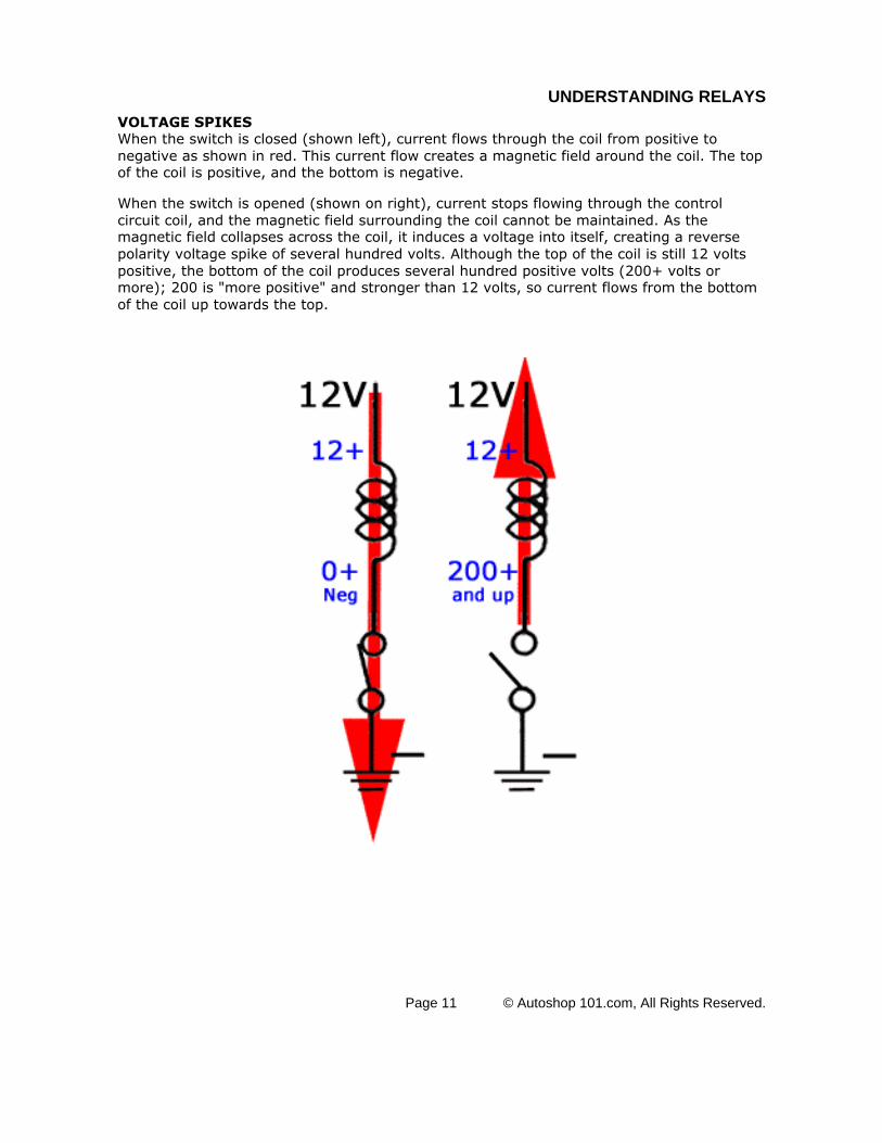
VOLTAGE SPIKESWhen the switch is closed (shown left), current flows through the coil from positive tonegative as shown in red. This current flow creates a magnetic field around the coil. The topof the coil is positive, and the bottom is negative.
When the switch is opened (shown on right), current stops flowing through the controlcircuit coil, and the magnetic field surrounding the coil cannot be maintained. As themagnetic field collapses across the coil, it induces a voltage into itself, creating a reversepolarity voltage spike of several hundred volts. Although the top of the coil is still 12 voltspositive, the bottom of the coil produces several hundred positive volts (200+ volts ormore); 200 is "more positive" and stronger than 12 volts, so current flows from the bottomof the coil up towards the top.
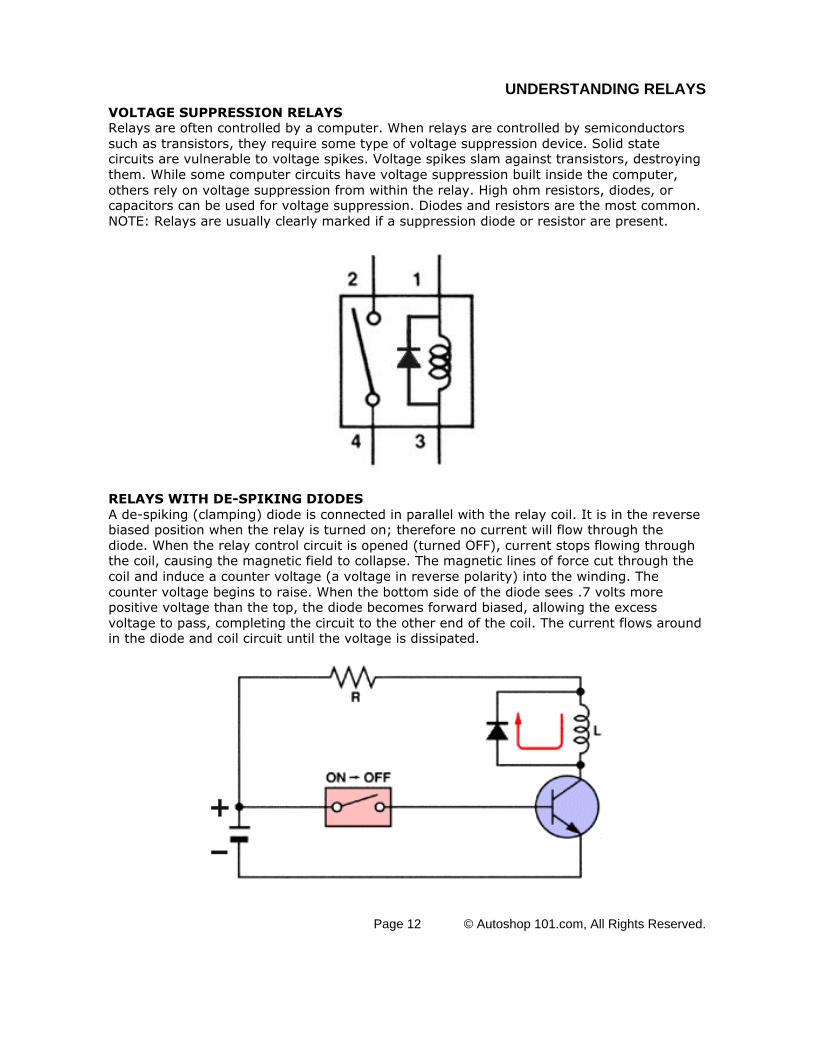
VOLTAGE SUPPRESSION RELAYSRelays are often controlled by a computer. When relays are controlled by semiconductorssuch as transistors, they require some type of voltage suppression device. Solid statecircuits are vulnerable to voltage spikes. Voltage spikes slam against transistors, destroyingthem. While some computer circuits have voltage suppression built inside the computer,others rely on voltage suppression from within the relay. High ohm resistors, diodes, orcapacitors can be used for voltage suppression. Diodes and resistors are the most common.NOTE: Relays are usually clearly marked if a suppression diode or resistor are present.
RELAYS WITH DE-SPIKING DIODESA de-spiking (clamping) diode is connected in parallel with the relay coil. It is in the reversebiased position when the relay is turned on; therefore no current will flow through thediode. When the relay control circuit is opened (turned OFF), current stops flowing throughthe coil, causing the magnetic field to collapse. The magnetic lines of force cut through thecoil and induce a counter voltage (a voltage in reverse polarity) into the winding. Thecounter voltage begins to raise. When the bottom side of the diode sees .7 volts morepositive voltage than the top, the diode becomes forward biased, allowing the excessvoltage to pass, completing the circuit to the other end of the coil. The current flows aroundin the diode and coil circuit until the voltage is dissipated.
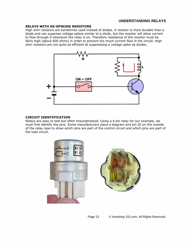
RELAYS WITH DE-SPIKING RESISTORSHigh ohm resistors are sometimes used instead of diodes. A resistor is more durable than adiode and can suppress voltage spikes similar to a diode, but the resistor will allow currentto flow through it whenever the relay is on. Therefore resistance of the resistor must befairly high (about 600 ohms) in order to prevent too much current flow in the circuit. Highohm resistors are not quite as efficient at suppressing a voltage spike as diodes.
CIRCUIT IDENTIFICATIONRelays are easy to test but often misunderstood. Using a 4 pin relay for our example, wemust first identify the pins. Some manufacturers place a diagram and pin ID on the outsideof the relay case to show which pins are part of the control circuit and which pins are part ofthe load circuit.
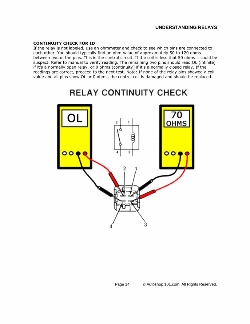
CONTINUITY CHECK FOR IDIf the relay is not labeled, use an ohmmeter and check to see which pins are connected toeach other. You should typically find an ohm value of approximately 50 to 120 ohmsbetween two of the pins. This is the control circuit. If the coil is less that 50 ohms it could besuspect. Refer to manual to verify reading. The remaining two pins should read OL (infinite)if it's a normally open relay, or 0 ohms (continuity) if it's a normally closed relay. If thereadings are correct, proceed to the next test. Note: If none of the relay pins showed a coilvalue and all pins show OL or 0 ohms, the control coil is damaged and should be replaced.
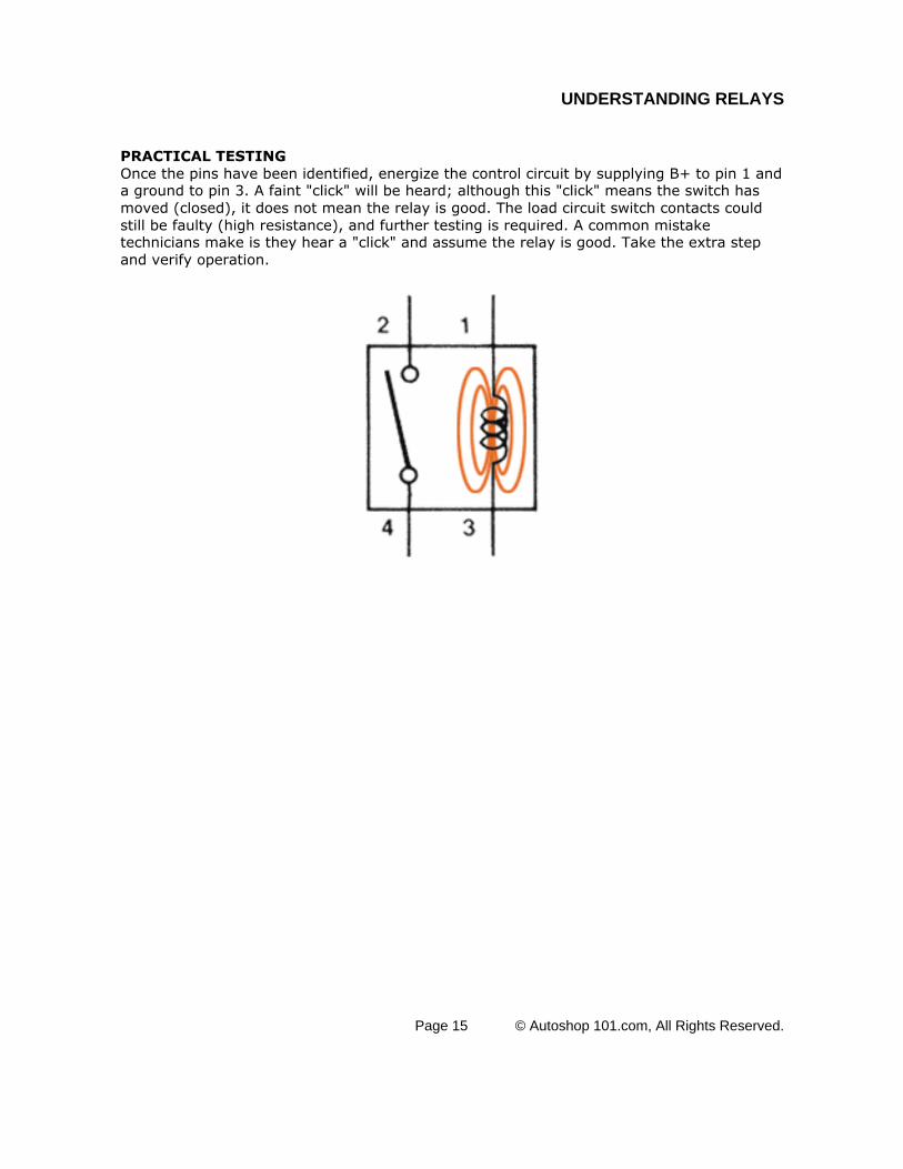
PRACTICAL TESTINGOnce the pins have been identified, energize the control circuit by supplying B+ to pin 1 anda ground to pin 3. A faint "click" will be heard; although this "click" means the switch hasmoved (closed), it does not mean the relay is good. The load circuit switch contacts couldstill be faulty (high resistance), and further testing is required. A common mistaketechnicians make is they hear a "click" and assume the relay is good. Take the extra stepand verify operation.
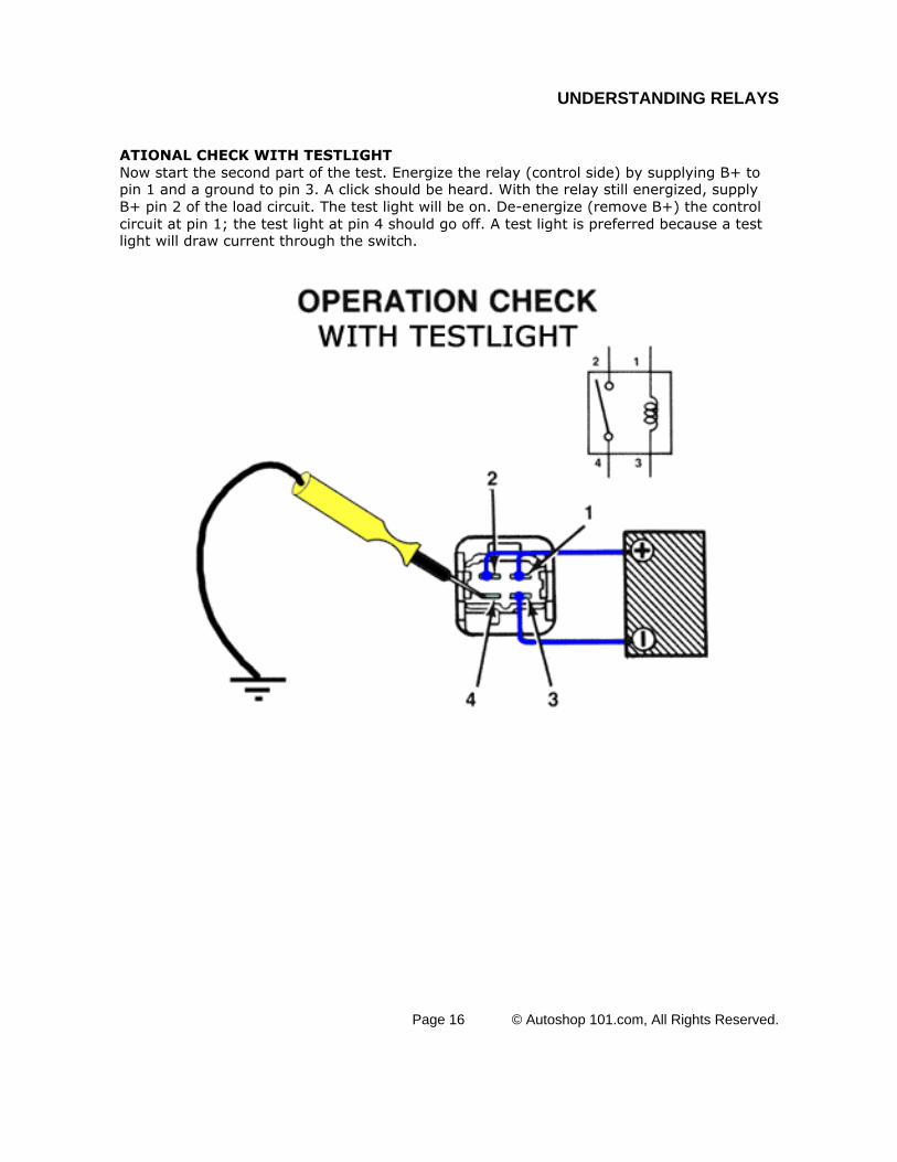
ATIONAL CHECK WITH TESTLIGHTNow start the second part of the test. Energize the relay (control side) by supplying B+ topin 1 and a ground to pin 3. A click should be heard. With the relay still energized, supplyB+ pin 2 of the load circuit. The test light will be on. De-energize (remove B+) the controlcircuit at pin 1; the test light at pin 4 should go off. A test light is preferred because a testlight will draw current through the switch.
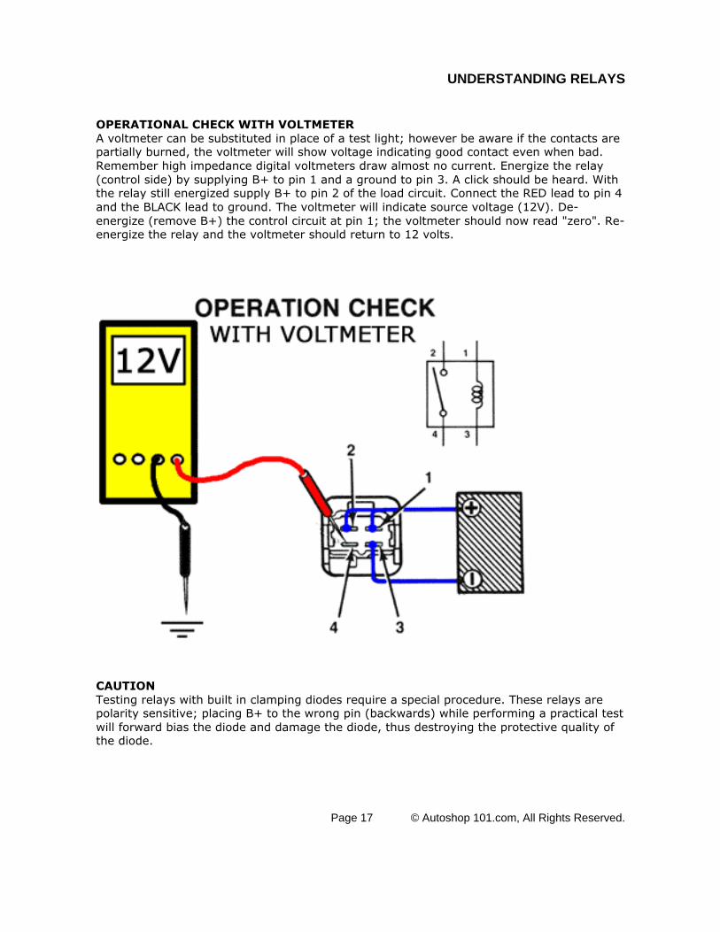
OPERATIONAL CHECK WITH VOLTMETERA voltmeter can be substituted in place of a test light; however be aware if the contacts arepartially burned, the voltmeter will show voltage indicating good contact even when bad.Remember high impedance digital voltmeters draw almost no current. Energize the relay(control side) by supplying B+ to pin 1 and a ground to pin 3. A click should be heard. Withthe relay still energized supply B+ to pin 2 of the load circuit. Connect the RED lead to pin 4and the BLACK lead to ground. The voltmeter will indicate source voltage (12V). De-energize (remove B+) the control circuit at pin 1; the voltmeter should now read "zero". Re-energize the relay and the voltmeter should return to 12 volts.
CAUTIONTesting relays with built in clamping diodes require a special procedure. These relays arepolarity sensitive; placing B+ to the wrong pin (backwards) while performing a practical testwill forward bias the diode and damage the diode, thus destroying the protective quality ofthe diode.
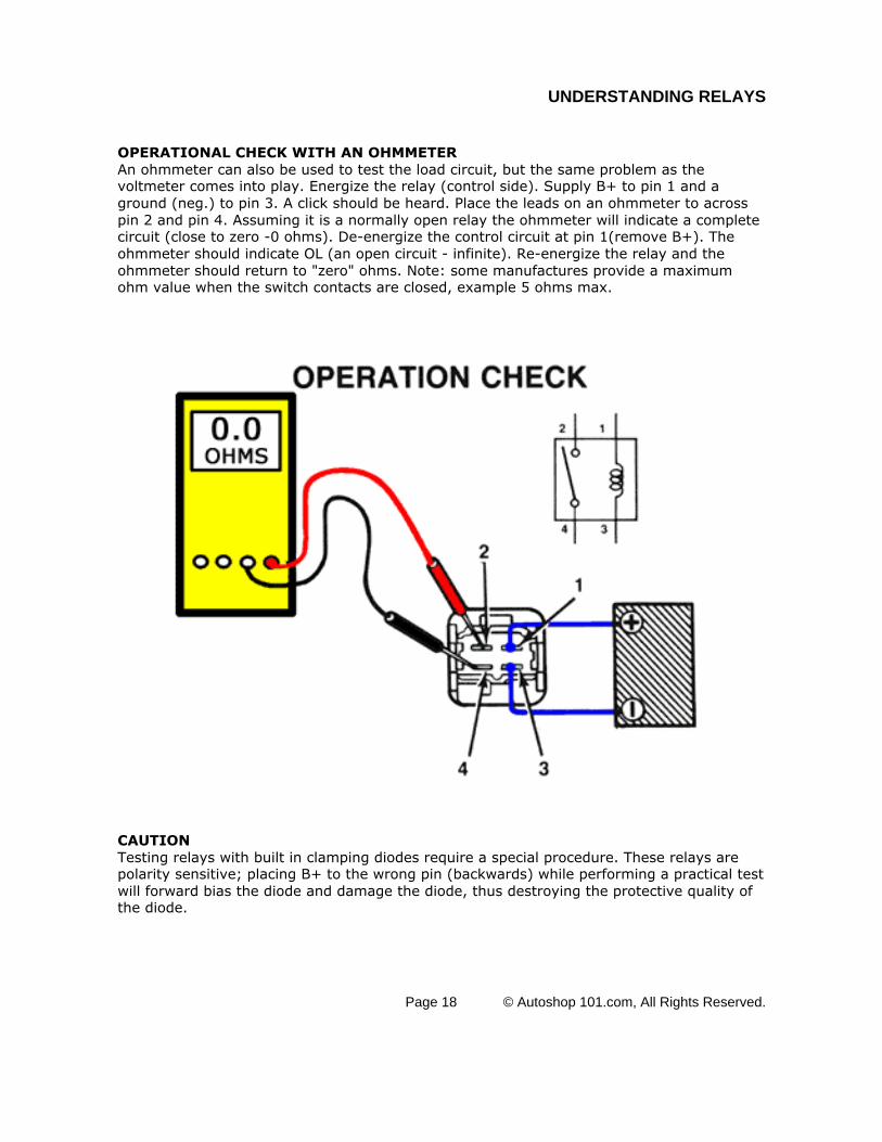
OPERATIONAL CHECK WITH AN OHMMETERAn ohmmeter can also be used to test the load circuit, but the same problem as thevoltmeter comes into play. Energize the relay (control side). Supply B+ to pin 1 and aground (neg.) to pin 3. A click should be heard. Place the leads on an ohmmeter to acrosspin 2 and pin 4. Assuming it is a normally open relay the ohmmeter will indicate a completecircuit (close to zero -0 ohms). De-energize the control circuit at pin 1(remove B+). Theohmmeter should indicate OL (an open circuit - infinite). Re-energize the relay and theohmmeter should return to "zero" ohms. Note: some manufactures provide a maximumohm value when the switch contacts are closed, example 5 ohms max.
CAUTIONTesting relays with built in clamping diodes require a special procedure. These relays arepolarity sensitive; placing B+ to the wrong pin (backwards) while performing a practical testwill forward bias the diode and damage the diode, thus destroying the protective quality ofthe diode.
OPERATIONAL CHECK FOR RELAY VOLTAGE SUPPRESSION DIODESAn ANALOG OHMMETER must be used. This test cannot be performed with a digital meter.The analog meter sends out a higher voltage which is required to forward bias the diode.Place the ohmmeter across the control circuit and record reading. Reverse the leads andcheck the control circuit again. A functioning diode will be indicated by have two differentreadings. A faulty diode will have the same reading in both directions.
Current from the ohmmeter flows through the control coil, in one direction. By reversing theleads, you send current in the opposite direction through the control coil. One of the twodirections the diode will be forward biased(on), creating two paths for current thus loweringresistance. With the leads in the other direction, the diode in will be reversed biased (off)creating only one path, with higher resistance.
1. What are the several designs of relays used today?
2. Describe the two circuits within a relay.
3. What is meant when the relay is de-energized?
4. Describe what is meant by N.O. or N.C relays. Draw and example of each and indicate which is the most common.
5. Draw the three relay variations illustrated on page 12 or 27.
6. Describe what an ISO relay is and why it is used.
7. Draw both a 4 and a 5 - pin ISO relay. Be sure to indicate the correct circuit ID (pin numbers).
8. Why are voltage spikes a problem with relays? Be sure to indicate how the spike is created.
9. Explain how voltage suppression is controlled in a relay. Provide a drawing of each type.
10. Describe in detail the procedure to identify the relay type when it is not labeled on the outside of the relay.
11. Explain how to properly test a 4-pin relay for correct operation.
12. How many options for testing relays were provided in this training module.
13. Explain how to properly test a suppression diode inside the relay.
14. Please provide feedback on this training module. I am not looking for a kiss up answer but rather an honest response. Be sure to include what you liked and did not like about the training module.


![[ 3000 Series Time Delay Relays and Measuring Relays ... · [ 3000 Series Time Delay Relays and Measuring Relays ] ... Measuring Relays ] • Time Delay Relays ... Dear Reader, Dear](https://static.documents.pub/doc/80x56/5b85683b7f8b9aec488e43dd/-3000-series-time-delay-relays-and-measuring-relays-3000-series-time.jpg)
