20
Understanding Shale Gas in Canada
Understanding Shale Gasin Canada
What is Shale Gas?
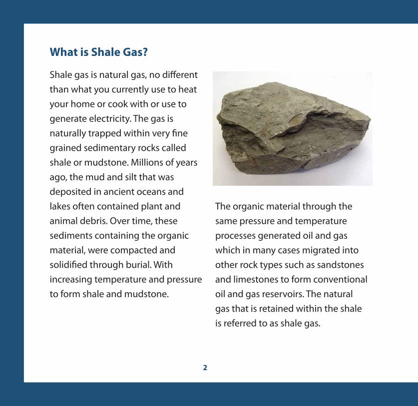
Shale gas is natural gas, no di�erent than what you currently use to heat your home or cook with or use to generate electricity. The gas is naturally trapped within very �ne grained sedimentary rocks called shale or mudstone. Millions of years ago, the mud and silt that was deposited in ancient oceans and lakes often contained plant and animal debris. Over time, these sediments containing the organic material, were compacted and solidi�ed through burial. With increasing temperature and pressure to form shale and mudstone.
The organic material through the same pressure and temperature processes generated oil and gas which in many cases migrated into other rock types such as sandstones and limestones to form conventional oil and gas reservoirs. The natural gas that is retained within the shale is referred to as shale gas.

Shale and mud rich rocks often vary in colour as well as grain size. Colours may vary from dark brown or grey through to black shale (a), like the Utica Formation in Quebec or the shales of the Horn River Basin in British Columbia. In some basins, often the �ne grained shale rocks are interbedded with coarser grained siltstones (b). Where structural processes have been at work, the shale rocks can be fractured (c) creating natural pathways for natural gas or oil to �ow to the wellbore.
(a) (b) (c)
How is Natural Gas Stored in Shale?
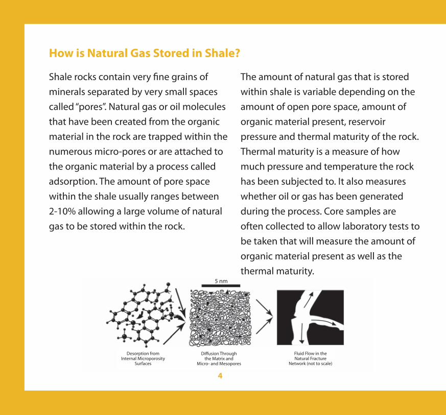
Shale rocks contain very �ne grains of minerals separated by very small spaces called “pores”. Natural gas or oil molecules that have been created from the organic material in the rock are trapped within the numerous micro-pores or are attached to the organic material by a process called adsorption. The amount of pore space within the shale usually ranges between 2-10% allowing a large volume of natural gas to be stored within the rock.
The amount of natural gas that is stored within shale is variable depending on the amount of open pore space, amount of organic material present, reservoir pressure and thermal maturity of the rock. Thermal maturity is a measure of how much pressure and temperature the rock has been subjected to. It also measures whether oil or gas has been generated during the process. Core samples are often collected to allow laboratory tests to be taken that will measure the amount of organic material present as well as the thermal maturity.
Desorption fromInternal Microporosity
Surfaces
Di�usion Throughthe Matrix and
Micro- and Mesopores
Fluid Flow in the Natural Fracture
Network (not to scale)
5 nm
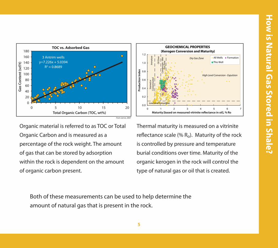
Organic material is referred to as TOC or Total
Organic Carbon and is measured as a
percentage of the rock weight. The amount
of gas that can be stored by adsorption
within the rock is dependent on the amount
of organic carbon present.
Thermal maturity is measured on a vitrinite
re�ectance scale (% Ro). Maturity of the rock
is controlled by pressure and temperature
burial conditions over time. Maturity of the
organic kerogen in the rock will control the
type of natural gas or oil that is created.
GEOCHEMICAL PROPERTIES(Kerogen Conversion and Maturity)
0.0
0.2
0.4
0.6
0.8
1.0
1.2
0 1 2 3 4 5 6 7
Prod
uctio
n In
dex
All Wells Formation
This Well
Maturity [based on measured vitrinite re�ectance in oil], % Ro
High Level Conversion - Expulsion
Cond
ensa
te -
Wet
Gas
Zon
e
Low Level Conversion
Stai
ned
orCo
ntam
inat
edIm
mat
ure
Dry Gas Zone
Oil
Zone
TOC vs. Adsorbed Gas180
160
140
120
100
80
60
40
20
020151050
Total Organic Carbon (TOC, wt%)
Gas
Con
tent
(scf
/t)
3 Antrim wellsy=7.226x + 5.0394
R2 = 0.8689
From Jarvie, 2007
Both of these measurements can be used to help determine the amount of natural gas that is present in the rock.

Shale rocks containing natural gas can be found in most sedimentary basins across the country. The largest concentration lies within the Western Canada Sedimentary Basin (WCSB) which extends from northeast British Columbia to southwest Manitoba. Other basins are located in the Arctic, Northwest Territories, Yukon, Quebec, southern Ontario, New Brunswick and Nova Scotia.
Shale gas resources in Canada are estimated to be greater than 1100 Tcf (trillion cubic feet) or 31 x 1012 m3 (cubic meters) with the majority residing within the WCSB.
Marketable resources, as de�ned by CSUG, represent the amount of gas that may be recovered from production operations. These estimates account for a de�ned recovery factor for each basin as well as discounting for natural gas used in the production process. In addition, marketable resources also re�ect regions where access to resources may be di�cult due to potential stakeholder, technical, or other issues. Marketable resources for shale gas in Canada are estimated to range from 128 to 343 Tcf (3.6 to 9.7x10¹² m3). To put this number in context, in 2009 Canada produced 5.26 Tcf (149x109 m3) of natural gas. Roughly 50% of the natural gas produced in Canada is exported. The other 50% is usedwithin the country to heat homes and businesses and by industry as a clean energy source for wellsite operations.
Where is Shale Gas Found in Canada?

Distribution of major shale gas basins in CanadaAdapted with the permission of Natural Resources Canada 2010, courtesy of the Atlas of Canada.
Shale Resources - GIP(Gas in Place)
Arctic Islands
Besa River
Cordova Embayment
Horn River Basin
Maritimes
Ontario Paleozoic
NWT Cretaceous
NWT Devonian
Utica
Western Canada Sedimentary Basin (Colorado Group Only)
TOTAL Shale GIP
Undefined
Undefined
200
500
130
Undefined
Undefined
Undefined
181
100
1111
Undefined
Undefined
5.6 x10¹²
14.1 x10¹²
3.7 x10¹²
Undefined
Undefined
Undefined
5.1 x10¹²
2.8 x10¹²
31.3 x10¹²
Tcf (trillion cubic feet)
m3
(cubic metres)
Arctic Islands
Besa River
NWT Cretaceous
NWT Devonian
Cordova EmbaymentHorn River Basin
Western Canada Sedimentary Basin (Colorado Group Only)
Ontario Paleozoic
Utica
Maritimes
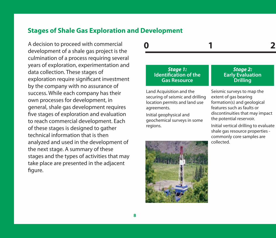
Stage 1: Identi�cation of the
Gas Resource
Stage 2: Early Evaluation
Drilling
A decision to proceed with commercial development of a shale gas project is the culmination of a process requiring several years of exploration, experimentation and data collection. These stages of exploration require signi�cant investment by the company with no assurance of success. While each company has their own processes for development, in general, shale gas development requires �ve stages of exploration and evaluation to reach commercial development. Each of these stages is designed to gather technical information that is then analyzed and used in the development of the next stage. A summary of these stages and the types of activities that may take place are presented in the adjacent �gure.
0 1 2
Seismic surveys to map the extent of gas bearing formation(s) and geological features such as faults or discontinuities that may impact the potential reservoir. Initial vertical drilling to evaluate shale gas resource properties - commonly core samples are collected.
Land Acquisition and the securing of seismic and drilling location permits and land use agreements. Initial geophysical and geochemical surveys in some regions.

3 4 5 20Approximate Time (in years)
Stage 4: Pilot Production
Testing
Stage 5:Commercial
DevelopmentProject
Reclamation
All stages of development include stakeholder dialogue and consultation
Drilling of multiple horizontal wells from a single pad as part of a full size pilot project. Optimization of completion techniques including drilling and multi-stage fracing and microseismic surveys .Pilot production testing.Planning and acquisition of pipeline right of ways for �eld development.
Drilling of initial horizontal well(s) to determine reservoir properties and completion techniques (includes some level of multi-stage fracturing).Continued drilling of vertical wells in additional regions of shale gas potential.Initial production tests.
Stage 3: Pilot Project Drilling
Commercial decision to proceed and government approvals for construction of gas plants, pipelines and drilling.
Pace of development is largely dependent on resource complexity, technical success, local circumstances and market conditions
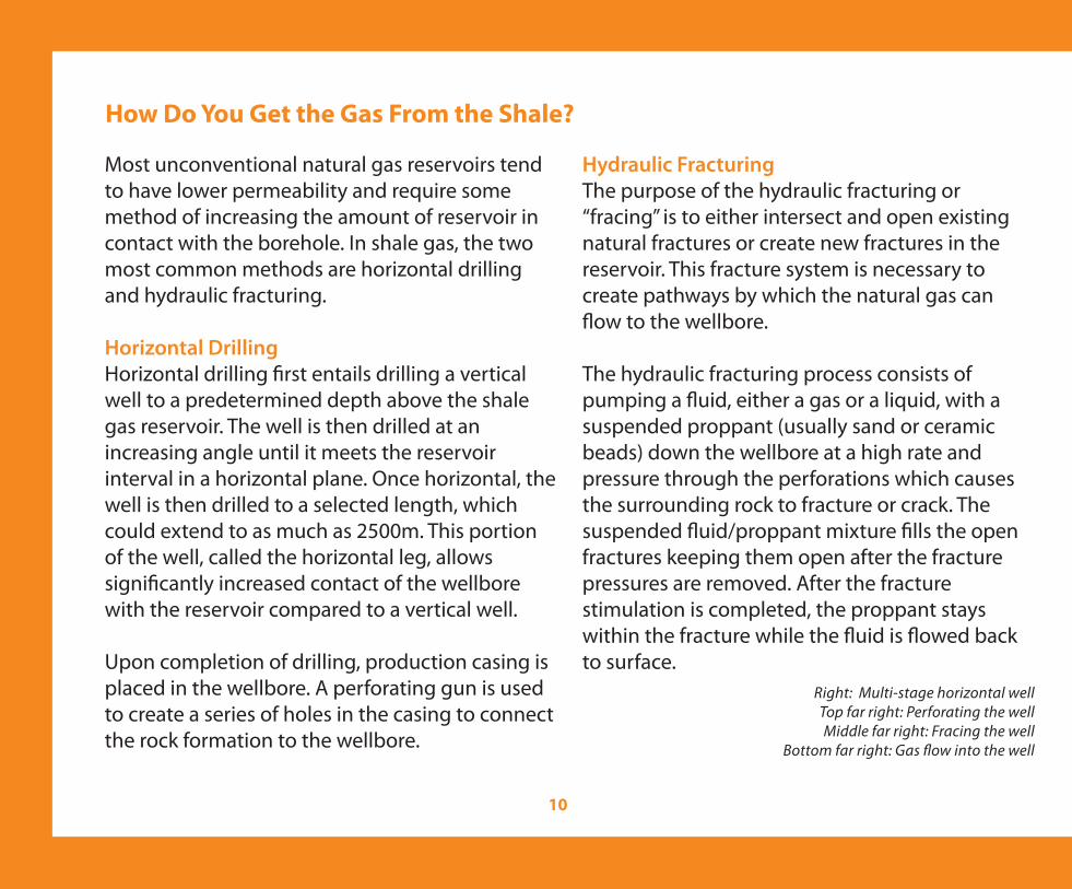
Most unconventional natural gas reservoirs tend to have lower permeability and require some method of increasing the amount of reservoir in contact with the borehole. In shale gas, the two most common methods are horizontal drilling and hydraulic fracturing.
Horizontal DrillingHorizontal drilling �rst entails drilling a vertical well to a predetermined depth above the shale gas reservoir. The well is then drilled at an increasing angle until it meets the reservoir interval in a horizontal plane. Once horizontal, the well is then drilled to a selected length, which could extend to as much as 2500m. This portion of the well, called the horizontal leg, allows signi�cantly increased contact of the wellbore with the reservoir compared to a vertical well.
Upon completion of drilling, production casing is placed in the wellbore. A perforating gun is used to create a series of holes in the casing to connect the rock formation to the wellbore.
Hydraulic FracturingThe purpose of the hydraulic fracturing or “fracing” is to either intersect and open existing natural fractures or create new fractures in the reservoir. This fracture system is necessary to create pathways by which the natural gas can �ow to the wellbore.
The hydraulic fracturing process consists of pumping a �uid, either a gas or a liquid, with a suspended proppant (usually sand or ceramic beads) down the wellbore at a high rate and pressure through the perforations which causes the surrounding rock to fracture or crack. The suspended �uid/proppant mixture �lls the open fractures keeping them open after the fracture pressures are removed. After the fracture stimulation is completed, the proppant stays within the fracture while the �uid is �owed back to surface.
Right: Multi-stage horizontal wellTop far right: Perforating the wellMiddle far right: Fracing the well
Bottom far right: Gas �ow into the well

Multi-Stage FracingIn most horizontal wells that have an extended horizontal leg section, multiple fracturing operations are necessary in order to e�ectively stimulate the reservoir rock. This process is called “multi-stage” fracing and consists of dividing the horizontal leg into sections which are then fractured independently. During the fracing operation, each “stage” is isolated from the rest of the wellbore using various types of plugs or packers (seals). Upon completion of all fracture stages, the plugs or packers are removed and all stages of the wellbore are allowed to �ow back to the surface.

Developing shale gas resources requires water for drilling and typically also requires the use of water for hydraulic fracturing before the well can produce natural gas. Water is the most common fracturing �uid, although in some shale gas reservoirs where the reservoir rock is not compatible with water, carbon dioxide, nitrogen or propane are used. Potentially tens of thousands of cubic meters of water could be required to properly frac a deep horizontal shale well. However, this operation typically takes places only once per fractured well, at the beginning of the well operation. Most wells then produce for 20 to 30 years without requiring any further fracturing and related water use.
In the early stages of shale gas development, the water used is typically withdrawn from fresh water sources. Natural gas producers, however, are increasingly using methods such as water recycling techniques or fracturing with non-potable brackish water to o�set increased demand for water and to reduce impacts on surface water and aquifers. Water used is usually
trucked or piped to the well site where it is stored either in large ponds or tanks.
To help the �uid carry the proppant and to ensure that the proppant is being carried as far into the fractures as possible, a number of chemicals may be added to the �uid/proppant mixture. Individual companies will have their own proprietary combination of these chemicals but the combined concentrations are usually less than 1% of total volume of the �uid proppant mixture. During the �owback stage as much as half of the �uid is recovered. The water used for oil and gas production is considered to be consumed water, since it comes into contact with hydrocarbons and other contaminants and cannot be returned to the environment without additional treatment. Increasingly companies are looking to treat the �uids used for fracturing and recycle them. If the �uid is not recycled, it is recovered and disposed of as required by provincial regulations.
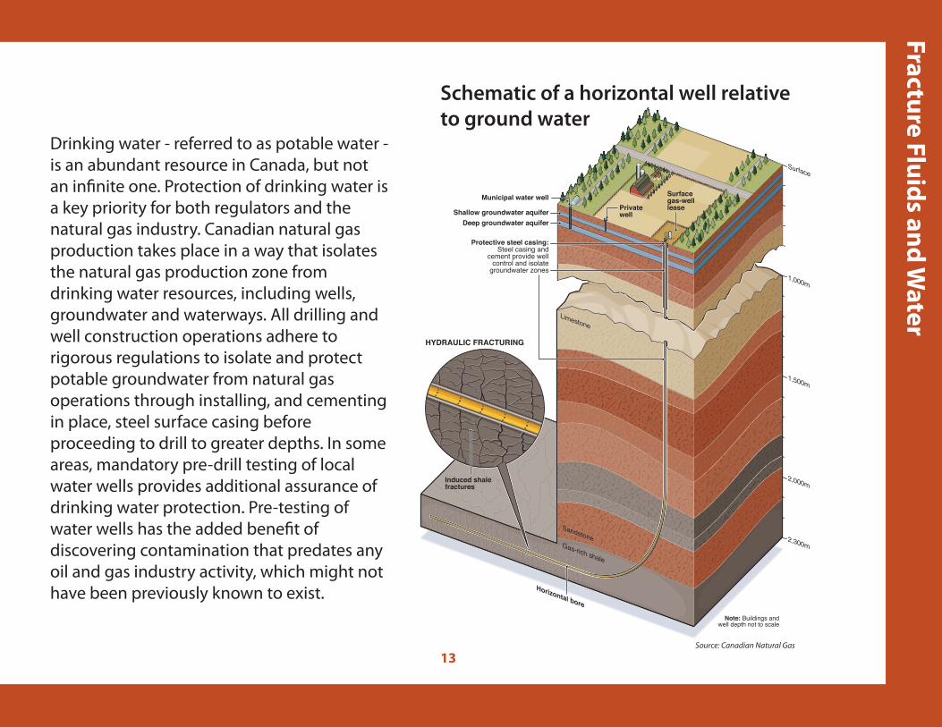
Gas-rich shale
SandstoneSandstone
LimestoneLimestone
HYDRAULIC FRACTURING
Shallow groundwater aquiferDeep groundwater aquifer
Protective steel casing:Steel casing and
cement provide wellcontrol and isolate
groundwater zones
Municipal water wellPrivatewell
Surface gas-well lease
Horizontal bore
Induced shale fractures
Note: Buildings andwell depth not to scale
1,000m
Surface
2,000m
2,300m
1,500m
Drinking water - referred to as potable water - is an abundant resource in Canada, but not an in�nite one. Protection of drinking water is a key priority for both regulators and the natural gas industry. Canadian natural gas production takes place in a way that isolates the natural gas production zone from drinking water resources, including wells, groundwater and waterways. All drilling and well construction operations adhere to rigorous regulations to isolate and protect potable groundwater from natural gas operations through installing, and cementing in place, steel surface casing before proceeding to drill to greater depths. In some areas, mandatory pre-drill testing of local water wells provides additional assurance of drinking water protection. Pre-testing of water wells has the added bene�t of discovering contamination that predates any oil and gas industry activity, which might not have been previously known to exist.
Source: Canadian Natural Gas
Schematic of a horizontal well relative to ground water

The production of shale gas relies heavily on the application of technology to e�ectively access the reservoirs containing natural gas. It is important for companies to have a clear understanding of how the reservoir has responded to the fracturing process as well as the ability to predict how much gas will be recovered from the fracture interval in the horizontal or vertical wellbore. This knowledge allows the natural gas �eld to be developed in a way that will optimize recovery of the resource.
Drilling and fracing is costly and requires large amounts of equipment and materials. The application of logistic processes that lower development costs while at the same time increasing well productivity and recoverable reserves are important for economic success. Companies often adopt a “manufacturing” style of development in order to achieve these cost savings. For shale gas development drilling multiple wells from a single pad is often used. Multi-well pads not only decrease the environmental footprint of the operations, but allow operational e�ciencies to be achieved.
In addition to information about the composition and physical properties of the shale, companies often use a variety of techniques to better understand the e�ectiveness of the drilling and completion operations. Production logging, microseismic and frac tracers are some of the examples of the tools that are used. During the fracturing process, microseismic events are created that can be recorded from nearby monitoring wells or surface seismic recording devices. This process, called microseismic monitoring, allows the orientation, distance and complexity of the fracturing events to be observed and modeled. Importantly, the application of microseismic monitoring identi�es both the lateral and vertical extent of induced fracturing. The location of the opened fractures, both vertically and horizontally allows companies to develop a plan for additional wells that will ensure that production from the reservoir e�ectively recovers as much natural gas as possible. Microseismic monitoring allows the volume of reservoir rock that has been stimulated to be determined and an estimate of total recoverable natural gas to be made.

15
Source: Apache Canada Ltd., copyright pending
This Frac Map tells us the measured frac height development is ~ 250 meters total and about 2 kilometers deeper than any groundwater aquifers.
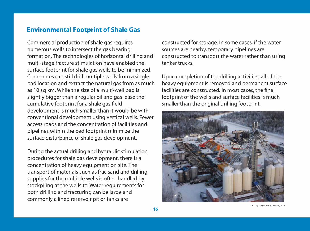
Commercial production of shale gas requires numerous wells to intersect the gas bearing formation. The technologies of horizontal drilling and multi-stage fracture stimulation have enabled the surface footprint for shale gas wells to be minimized. Companies can still drill multiple wells from a single pad location and extract the natural gas from as much as 10 sq km. While the size of a multi-well pad is slightly bigger than a regular oil and gas lease the cumulative footprint for a shale gas �eld development is much smaller than it would be with conventional development using vertical wells. Fewer access roads and the concentration of facilities and pipelines within the pad footprint minimize the surface disturbance of shale gas development.
During the actual drilling and hydraulic stimulation procedures for shale gas development, there is a concentration of heavy equipment on site. The transport of materials such as frac sand and drilling supplies for the multiple wells is often handled by stockpiling at the wellsite. Water requirements for both drilling and fracturing can be large and commonly a lined reservoir pit or tanks are
constructed for storage. In some cases, if the water sources are nearby, temporary pipelines are constructed to transport the water rather than using tanker trucks.
Upon completion of the drilling activities, all of the heavy equipment is removed and permanent surface facilities are constructed. In most cases, the �nal footprint of the wells and surface facilities is much smaller than the original drilling footprint.
Courtesy of Apache Canada Ltd., 2010
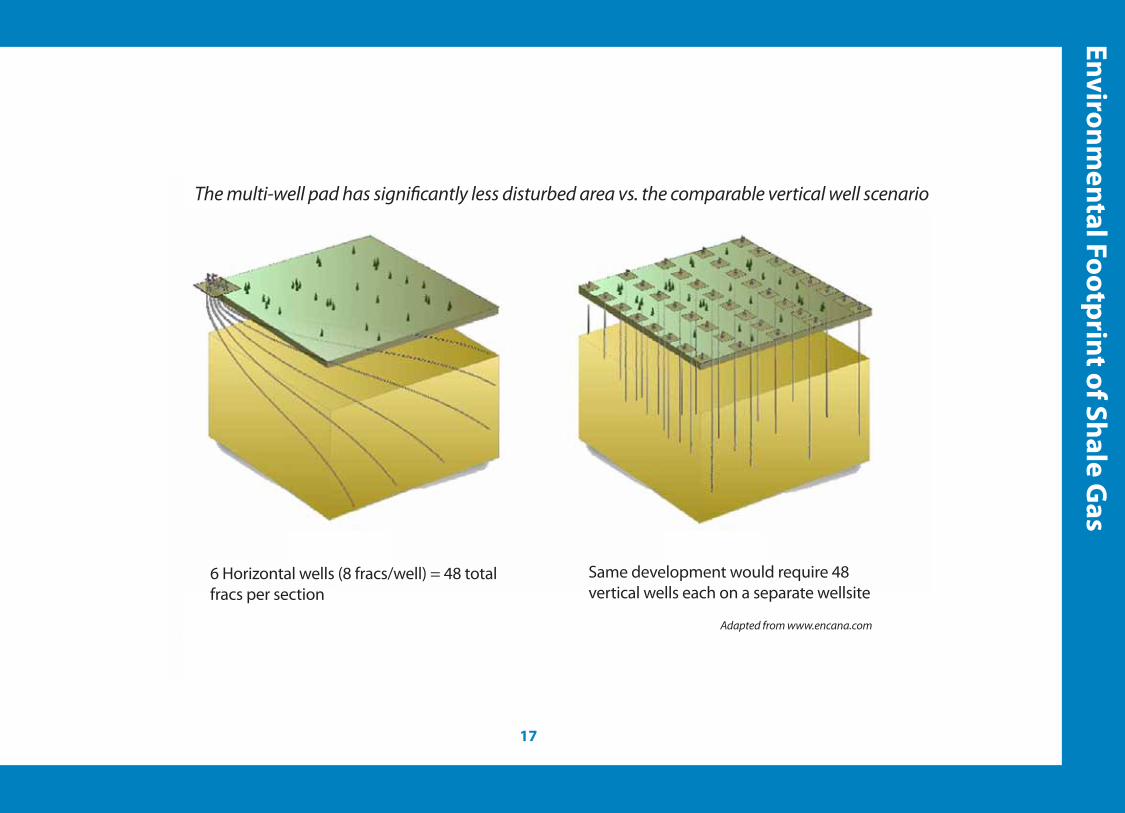
The multi-well pad has signi�cantly less disturbed area vs. the comparable vertical well scenario
6 Horizontal wells (8 fracs/well) = 48 total fracs per section
Same development would require 48 vertical wells each on a separate wellsite
Adapted from www.encana.com
Glossary & Terminology
Adsorption/Adsorbed: Refers to the molecular bonding
of a gas to the surface of a solid. In the case of shale,
natural gas is adsorbed or bonded to the organic material
in the shale.
Aquifer: The sub-surface layer of rock or unconsolidated
material that allows water to �ow within it. Aquifers can act
as sources for groundwater, both usable fresh water and
unusable salty water.
Casing: Steel pipe placed in a well and cemented in place
to isolate water, gas and oil from other formations and to
maintain hole stability.
Disposal Well: A well which injects produced water into a
regulated and approved deep underground formation for
disposal.
Drilling Mud: A mixture of clay, water and other
ingredients that are pumped downhole through the drill
pipe and drill bit that enable the removal of the drill
cuttings from the well bore and also stabilize the
penetrated rock formations before casing is installed in the
borehole.
Fault: A fracture surface in rocks along which movement
of rock on one side has occurred relative to rock on the
other side.
Formation (geologic): A rock body distinguishable from
other rock bodies and useful for mapping or description.
Formations may be combined into Groups or subdivided
into members.
Gas-in-Place (GIP): The hypothetical amount of gas
contained in a formation or rock unit. Gas-in-Place always
represents a value that is more than what is economically
recoverable and refers to the total resources that are
possible.
Horizontal Drilling: A drilling procedure in which the
wellbore is drilled vertically to a kick-o� depth above the
target formation and then angled through a wide 90
degree arc such that the producing portion of the well
extends horizontally through the target formation.

Hydraulic Fracturing (aka ‘Fracing’): A method of
improving the permeability of a reservoir by pumping �uids
such as water, carbon dioxide, nitrogen or propane into the
reservoir at su�cient pressure to crack or fracture the rock.
The opening of natural fractures or the creating of arti�cial
fractures to create pathways by which the natural gas can
�ow to the wellbore.
Microseismic: The process of using seismic recording
devices to measure the location of fractures that are created
during the hydraulic fracing process. Mapping of these
microseismic events allows the extent of fracture
development to be determined.
Permeability: A rock’s capacity to transmit a �uid or gas;
dependent upon the size and shape of pores and
interconnecting pore throats. A rock may have signi�cant
porosity (many microscopic pores) but have low
permeability if the pores are not interconnected.
Permeability may also exist or be enhanced through
fractures that connect the pores.
Porosity: The percentage of void space in a rock that may or
may not contain oil or gas.
Produced Water: Water produced from oil and gas wells.
Propping Agents/Proppants: Silica sand or other particles
pumped into a formation during a hydraulic fracturing
operation to keep fractures open and retain the induced
permeability.
Reserves: The estimated volume of gas economically
recoverable from single or multiple reservoirs. Reserve
estimates are based on strict site-speci�c engineering
criteria.
Reservoir: A porous and possibly permeable rock formation
containing oil or natural gas.
Shale Gas: Natural gas stored in low permeability shale
formations.
Stimulation: Any of several processes used to enhance near
reservoir permeability.

Canadian Society for Unconventional Gas (CSUG)
Suite 420, 237 - 8th Avenue SECalgary, AB T2G 5C3
Phone: 403-233-9298; Fax: 403-233-9267Email: [email protected]; Web: www.csug.ca
May not be reproduced without written permission from the Canadian Society for Unconventional Gas


