67
Applying the Fundamentals Understanding the Hydrodynamics in Biomass Gasifiers Ray Cocco June 14, 2012

Applying the Fundamentals
Understanding the Hydrodynamics in Biomass Gasifiers
Ray CoccoJune 14, 2012
Applying the Fundamentals
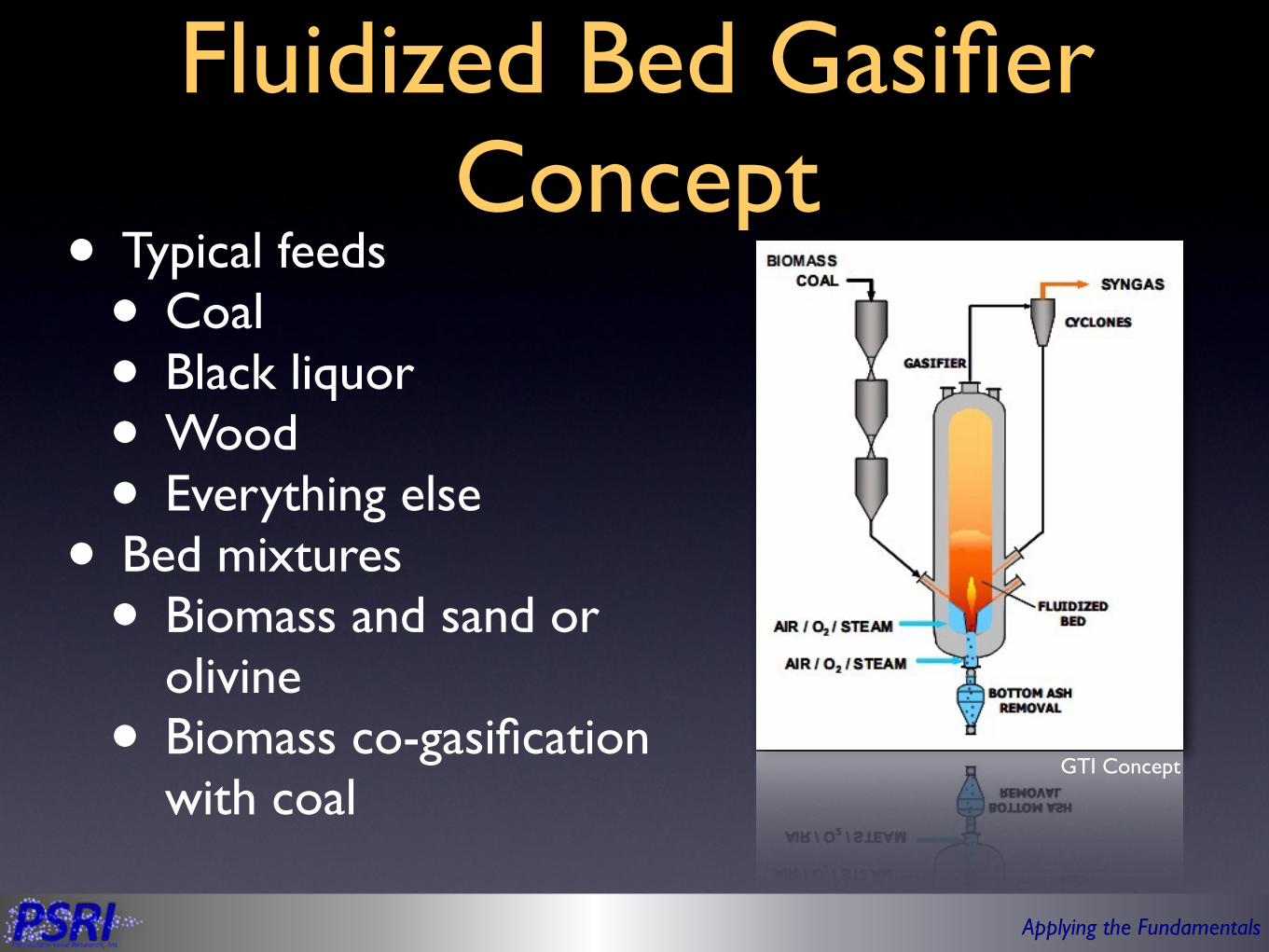
Fluidized Bed Gasifier Concept
• Typical feeds• Coal• Black liquor• Wood• Everything else
• Bed mixtures• Biomass and sand or
olivine• Biomass co-gasification
with coalGTI Concept
Applying the Fundamentals
Outline
• Particle behavior and flow regimes• Bed behavior• Entrainment• Bubble• Multiphase jet• Gas jets• Gas-liquid jets
• Summary
Applying the Fundamentals
Outline
• Particle behavior and flow regimes• Bed behavior• Entrainment• Bubble• Multiphase jet• Gas jets• Gas-liquid jets
• Summary

Applying the Fundamentals
Particle Properties
• Sand is “inert” and remains a Geldart Group B Particle• Coal is typical fed in as Geldart Group B but bed
properties can be more indicative of Geldart Group A
Sand
Coal
Higher Pressures
Applying the Fundamentals
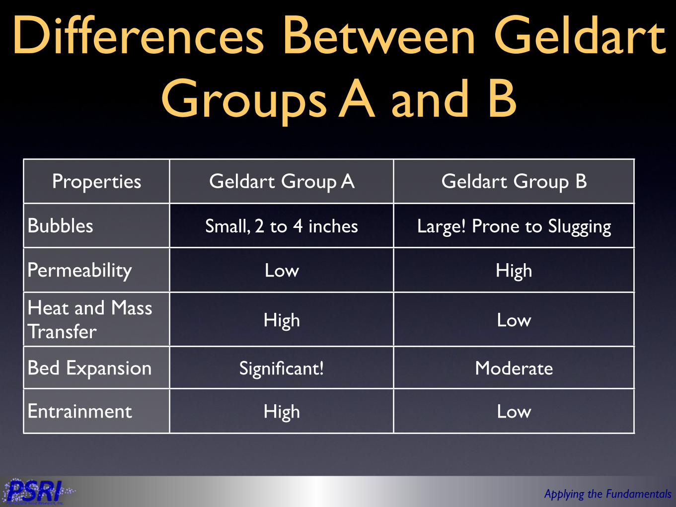
Differences Between Geldart Groups A and B
Properties Geldart Group A Geldart Group B
Bubbles
Permeability
Heat and Mass Transfer
Bed Expansion
Entrainment
Small, 2 to 4 inches Large! Prone to Slugging
Low High
High Low
Significant! Moderate
High Low

Applying the Fundamentals
Flow Regimes
• To date, most biomass gasifier concepts are bubbling and churning fluidized beds
Coal Gasification
Biomass Gasification
Applying the Fundamentals
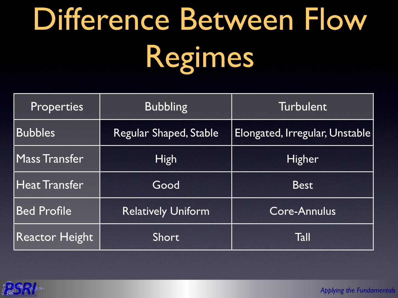
Difference Between Flow Regimes
Properties Bubbling Turbulent
Bubbles
Mass Transfer
Heat Transfer
Bed Profile
Reactor Height
Regular Shaped, Stable Elongated, Irregular, Unstable
High Higher
Good Best
Relatively Uniform Core-Annulus
Short Tall
Applying the Fundamentals
Outline
• Particle behavior and flow regimes• Bed behavior• Entrainment• Bubble• Multiphase jet• Summary
Applying the Fundamentals
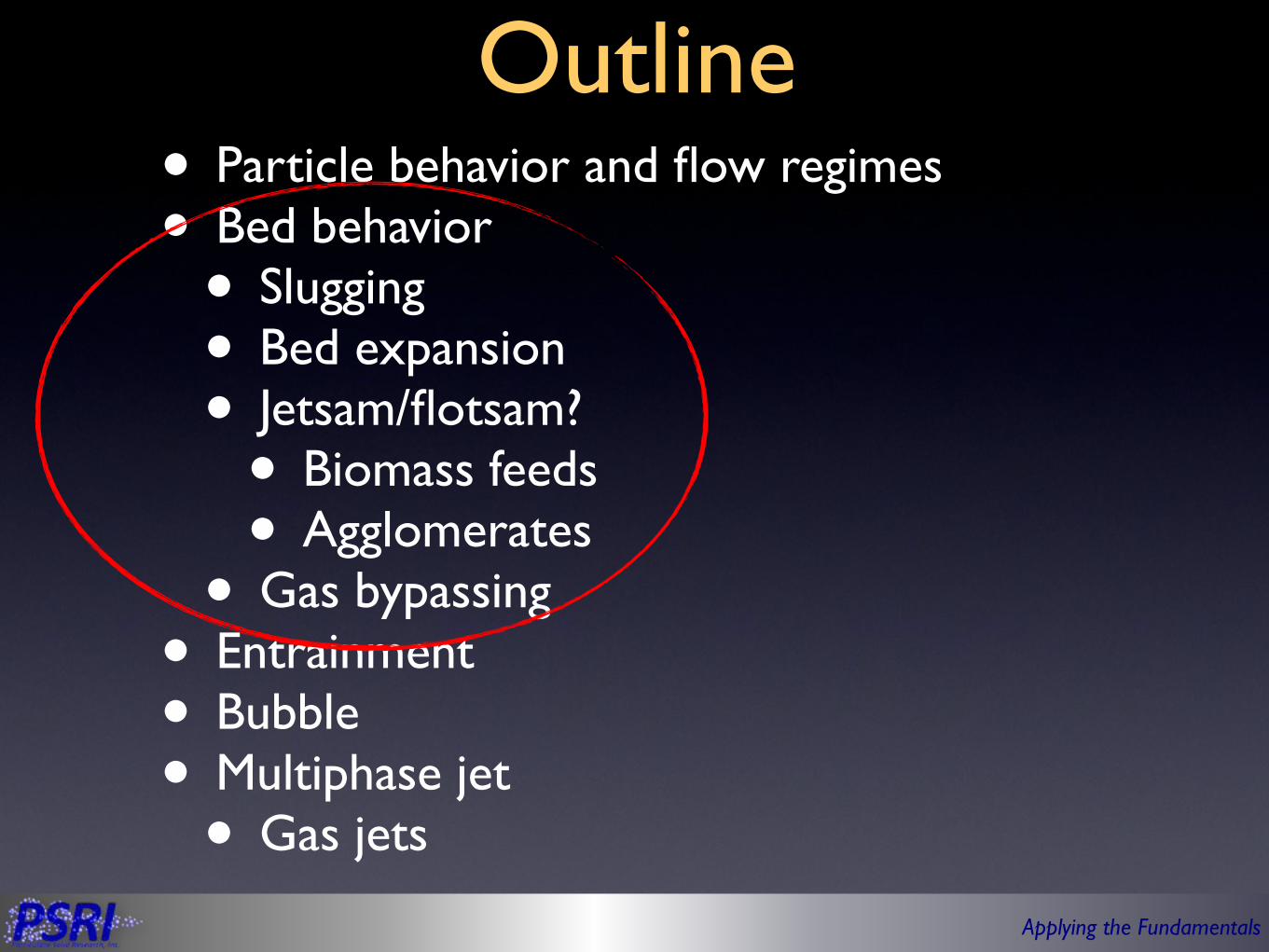
Outline• Particle behavior and flow regimes• Bed behavior• Slugging• Bed expansion• Jetsam/flotsam?• Biomass feeds• Agglomerates
• Gas bypassing• Entrainment• Bubble• Multiphase jet• Gas jets

Applying the Fundamentals
Slugging• Larger particles produce larger bubbles• Larger bubbles rise faster than smaller
bubbles• Bubbles larger than 2/3 the diameter of the
bed can cause the bed to slug• Issue with slugging• Unstable fluidization operation• May flood cyclones• Lower mass transfer• Residence time of gas in bubble• Surface to volume of exposure to
emulsion
Uo = 1 ft/sec

Applying the Fundamentals
Bed Expansion
0
37.5
75
112.5
150
Gro
up A
- Lo
w P
ress
ure
Gro
up A
- H
igh
Pres
sure
Gro
up B
- Lo
w P
ress
ure
Gro
up B
- H
igh
Pres
sure
Stagnant BedFluidized Bed
Stagnant Bed Fluidized Bed

Applying the Fundamentals
Jetsam & Flotsam - A Biomass Problem
• Coal injection into a 25-foot (7.6-m) diameter fluidized bed of coal
• Neutrally buoyant particles

Applying the Fundamentals
Jetsam & Flotsam - A Biomass Problem
• Little penetration in the bed• Particle buoyancy seems to be important
Applying the Fundamentals
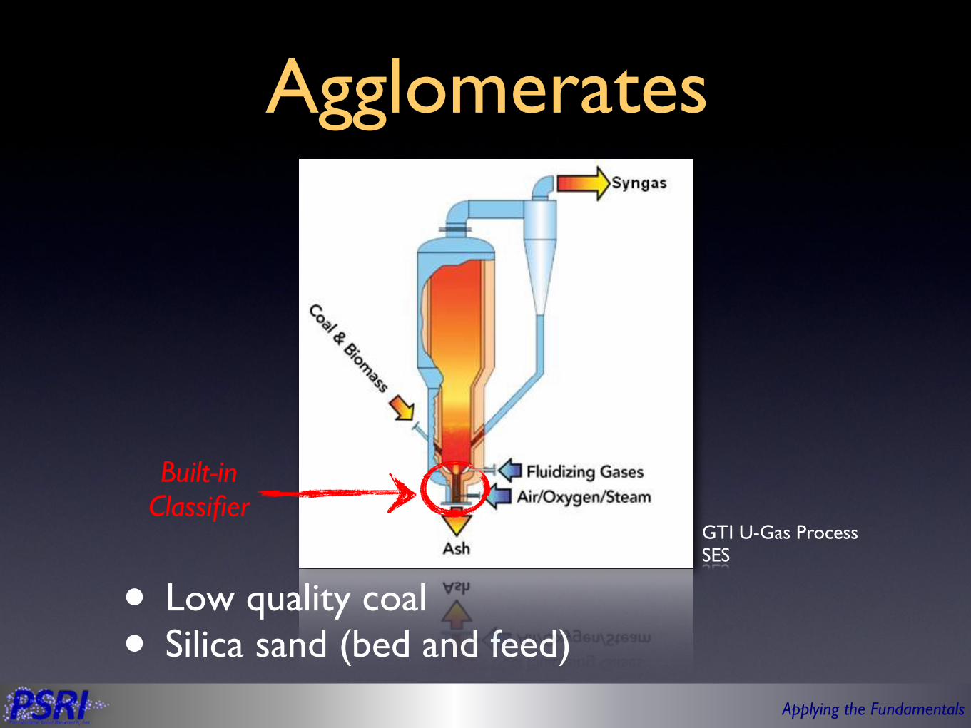
Agglomerates
• Low quality coal• Silica sand (bed and feed)
Built-in Classifier
GTI U-Gas ProcessSES
Applying the Fundamentals
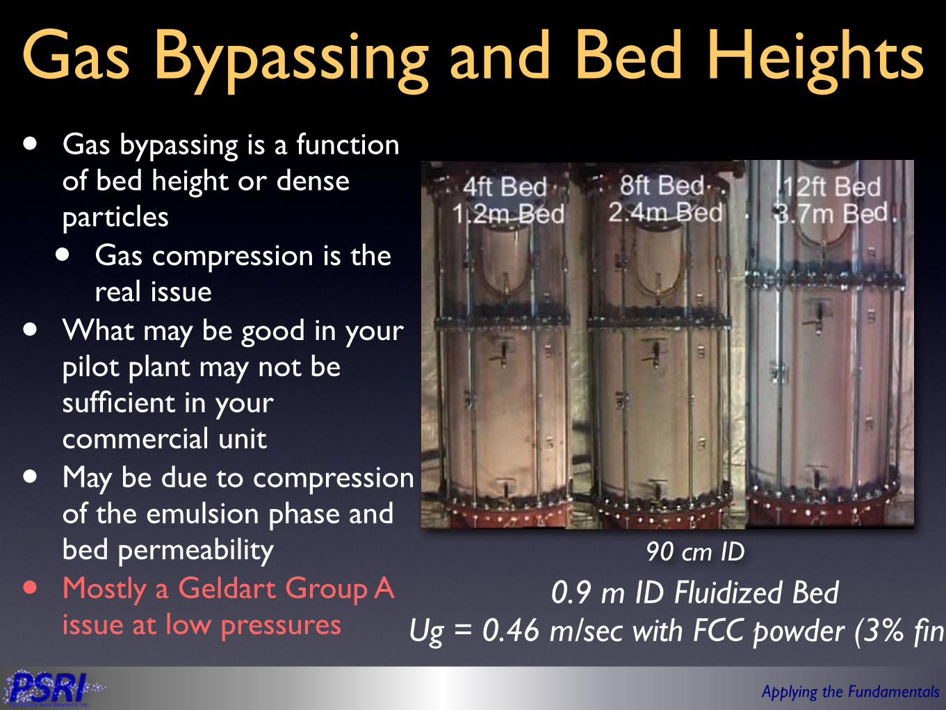
Gas Bypassing and Bed Heights• Gas bypassing is a function
of bed height or dense particles
• Gas compression is the real issue
• What may be good in your pilot plant may not be sufficient in your commercial unit
• May be due to compression of the emulsion phase and bed permeability
• Mostly a Geldart Group A issue at low pressures
0.9 m ID Fluidized BedUg = 0.46 m/sec with FCC powder (3% fines)
90 cm ID
Applying the Fundamentals
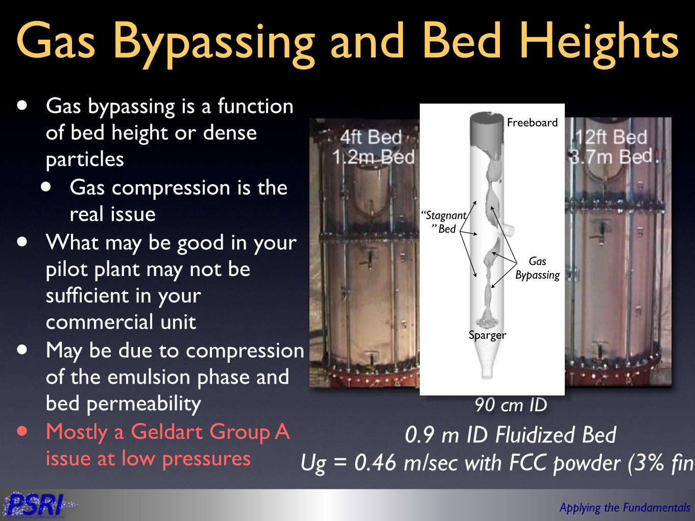
Gas Bypassing and Bed Heights• Gas bypassing is a function
of bed height or dense particles
• Gas compression is the real issue
• What may be good in your pilot plant may not be sufficient in your commercial unit
• May be due to compression of the emulsion phase and bed permeability
• Mostly a Geldart Group A issue at low pressures
0.9 m ID Fluidized BedUg = 0.46 m/sec with FCC powder (3% fines)
90 cm ID
“Stagnant” Bed
Sparger
Freeboard
Gas Bypassing

Applying the Fundamentals
Pressure Fluctuations as an Indicator of Gas Bypassing
• Pressure fluctuations increased when jet streaming was present• But this was mostly a local detection
No Jet Streaming Jet Streaming90 cm ID

Applying the Fundamentals
Precession of Gas Bypassing as Detected from Pressure Fluctuations
• Jet stream is not stationary
• It seems to precess around the vessel
90 cm ID
• Pressure taps need to be near jet stream
• As evidenced in signal fluctuations

Applying the Fundamentals
Managing Gas Bypassing• Jet streaming is a function of gas
permeability and bed weight
• Most with Geldart Group A powders
• Jet streaming can be managed
• Limiting the bed height
• Not always possible
• Adding particle fines
• Increasing the pressure
• More gas can get into the emulsion
• Adding baffles
16
14
12
10
8
6
4
2
0Stan
dard
Dev
iatio
n of
ΔP,
cm o
f H2O
1.00.80.60.40.20.0Superficial Air Velocity, m/sec
0.3 meter Column DiaLight FCC PowderStatic Bed Height
2 meters 0.8 meters
Gas Bypassing
No Gas Bypassing
14
12
10
8
6
4
2
0Stan
dard
Dev
iatio
n of
ΔP,
cm o
f H2O
1.21.00.80.60.40.2Superficial Air Velocity, m/sec
0.3 meter Column DiaLight FCC Powder
With Baffles No Baffles
4
3
2
1
0Max
Bed
Hei
ght w
/o B
ypas
sing
, m
1412108642% Fines (< 44 µm)
0.3 meters Column DiaLight FCC Powder
Ug = 0.46 m/sec Ug = 0.61 m/sec

Applying the Fundamentals
Effects of Imposed Solids Flux
3% Fines, No Flux 9% Fines, No Flux 3% Fines with Flux 9% Fines with Flux
SolidsVolumeFraction
2 ft/sec (0.6 m/sec) Superficial Gas Velocity
Barracuda®
High Loadings
Low Loadings
Applying the Fundamentals
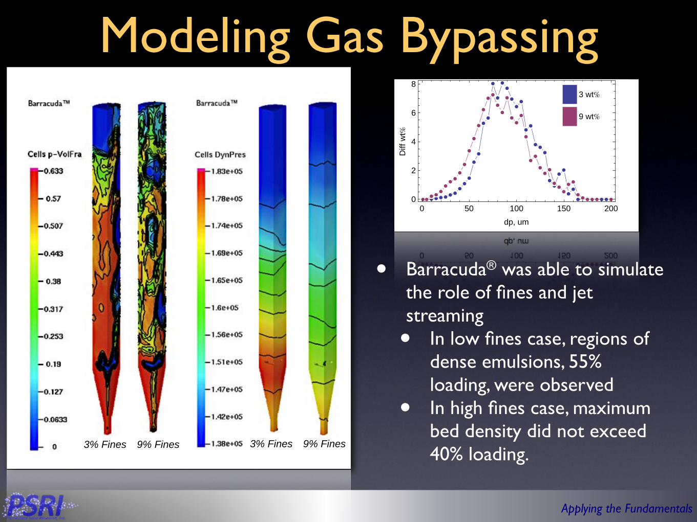
• Barracuda® was able to simulate the role of fines and jet streaming• In low fines case, regions of
dense emulsions, 55% loading, were observed
• In high fines case, maximum bed density did not exceed 40% loading.
Modeling Gas Bypassing
3% Fines
ÊÊÊÊÊÊÊÊÊÊÊ
Ê
Ê
ÊÊ
Ê
Ê
ÊÊ
ÊÊÊ
ÊÊ
ÊÊÊ
ÊÊ
ÊÊ
ÊÊ
ÊÊÊÊÊÊÊÊÊÊÊÊÊÊÊÊÊ
Ê
Ê
Ê
Ê
Ê
ÊÊ
ÊÊ
Ê
ÊÊÊ
Ê
ÊÊ
ÊÊÊ
ÊÊÊÊÊ
ÊÊÊÊÊ Ê
0 50 100 150 2000
2
4
6
8
dp, um
Diff
wt%
9 wt%
3 wt%
9% Fines 3% Fines 9% Fines

Applying the Fundamentals
Validation with Pressure Fluctuations• Barracuda™ was able to capture the trends
but over predicted pressure fluctuations for the imposed solids flux cases
P1
P2
P3
P4
P5
P6
ÊÊ
Ê
Ê
Ê ÊÊ
ÊÊ
Ê ÊÊ
Ê
Ê
Ê
Ê
Ê Ê
Ê
Ê Ê Ê
ÁÁ
Á
Á
Á
Á
Á
Á
Á
0.0 0.5 1.0 1.5 2.0 2.5 3.00
5
10
15
Superficial Gas Velocity, ftêsec
Pres
sure
Fluc
tuat
ions
,in
H2O
Case 4Case 3Case 2Case 1
• Denotes data ° Denotes simulation results
3% Fines, No Flux9% Fines, No Flux
3% Fines with Solids Flux9% Fines with Solids Flux
Applying the Fundamentals
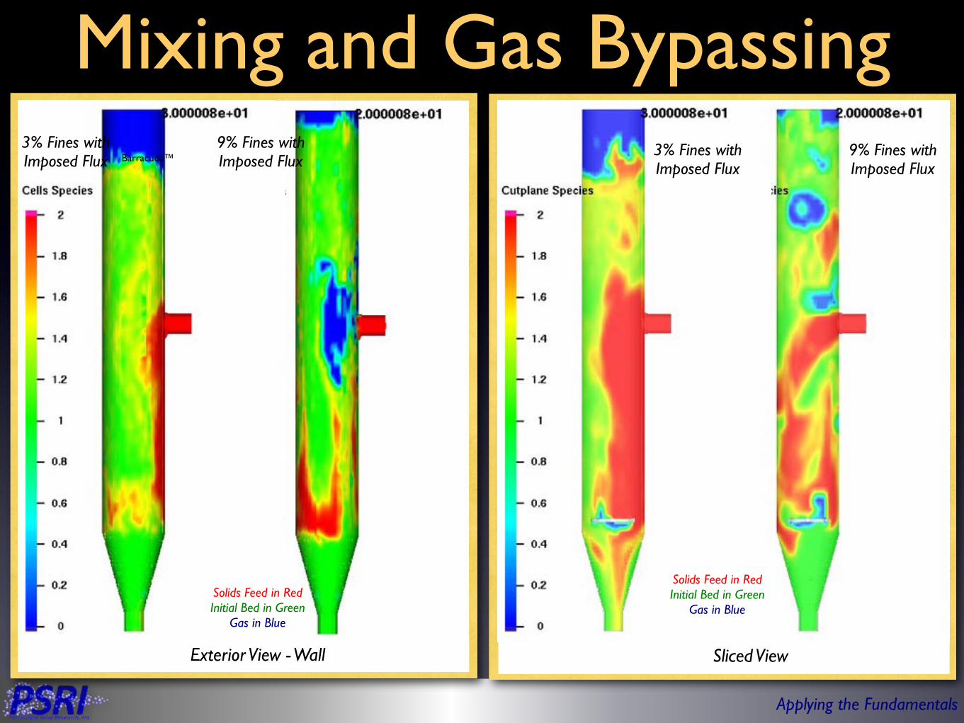
Sliced View
Mixing and Gas Bypassing
Solids Feed in RedInitial Bed in Green
Gas in Blue
Solids Feed in RedInitial Bed in Green
Gas in Blue
Barracuda™
Exterior View - Wall
3% Fines with Imposed Flux
9% Fines with Imposed Flux
3% Fines with Imposed Flux
9% Fines with Imposed Flux

Applying the Fundamentals
Gas Bypassing at the Interface
• Species legend• Species 0 - Gas• Species 1 - Bed• Species 2 - Dipleg
• Gas bypassing with low fines level appears to reside at the interface of bed particles and dipleg particles
3% Fines with Imposed Flux 9% Fines with Imposed Flux
Applying the Fundamentals
Outline
• Particle behavior and flow regimes• Bed behavior• Entrainment• Bubble• Multiphase jet• Summary
Applying the Fundamentals
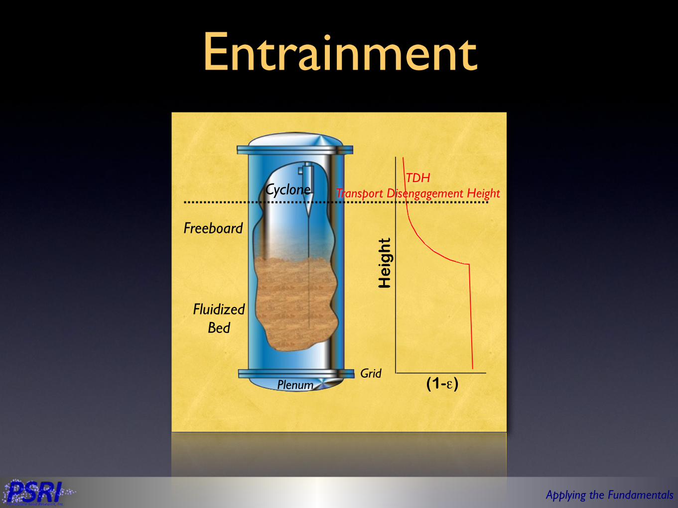
Entrainment
Fluidized Bed
PlenumGrid
Cyclone
Freeboard
(1-ε)
TDHTransport Disengagement Height
Applying the Fundamentals
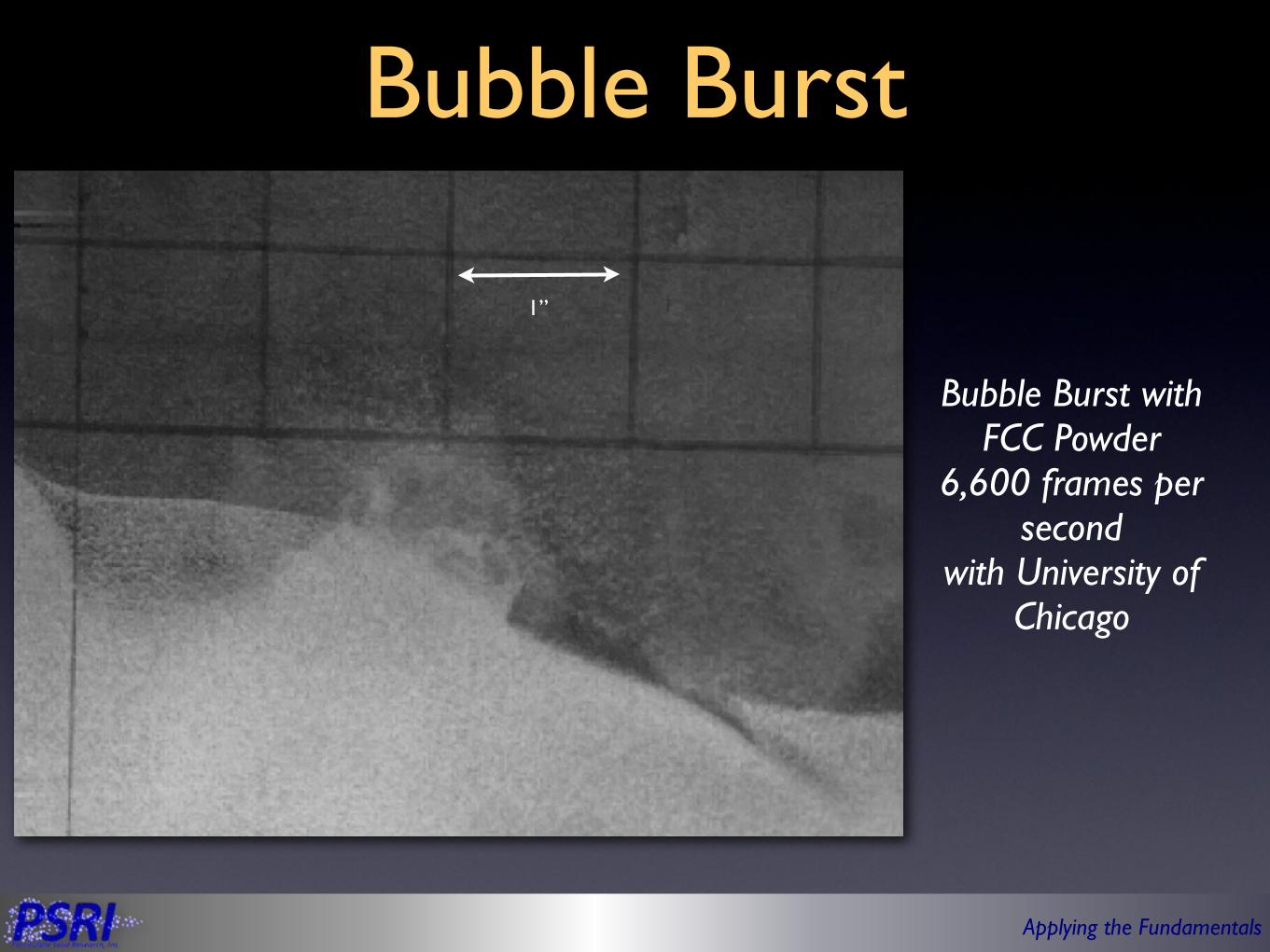
Bubble Burst
Bubble Burst with FCC Powder
6,600 frames per second
with University of Chicago
1”

Applying the Fundamentals
Calculated Entrainment Rates in a Fluidized Bed
• Why do we see such a wide range of entrainment rates for small particles?
• Are some smaller particles behaving differently than others?Entrainment rate calculations based on FCC catalyst
powder with 9% fines in a 3-meters ID x 12-meters tall fluidized bed with a bed height of 6 meters and superficial
gas velocity of 1 m/sec at room temperature
Stojkovski, V., Kostic’, Z., Thermal Science, 7 (2003) 43-58.Zenz, P.A., Weil, N.A., AIChE J., 4 (1958) 472-479.Lin, L, Sears, J.T., Wen, C.Y., Powder Technology, 27 (1980) 105-115.
M. Colakyan, N. Catipovic, G. Jovanovic, T.J. Fitzgerald, AIChE Symp. Ser. 77 (1981) 66.Colakyan, M., Levenspiel, O., Powder Technology, 38 (1984), pp. 223-232Geldart, D., Cullinan, J., Georghiades, S., Gilvray, D., Pope, D.J., Trans. Inst. Chem. Eng., 57 (1979) 269-277.

Applying the Fundamentals
Batch Fluidization Test
• Replicated what was experienced in a commercial fluidized bed reactor
• The increase in entrainment rate corresponded to a decrease in the fines level in the bed and with the entrained solids
Grid PlatePlenum
Bed
Vent
6” (15 cm) Fluidized
Bed
Applying the Fundamentals
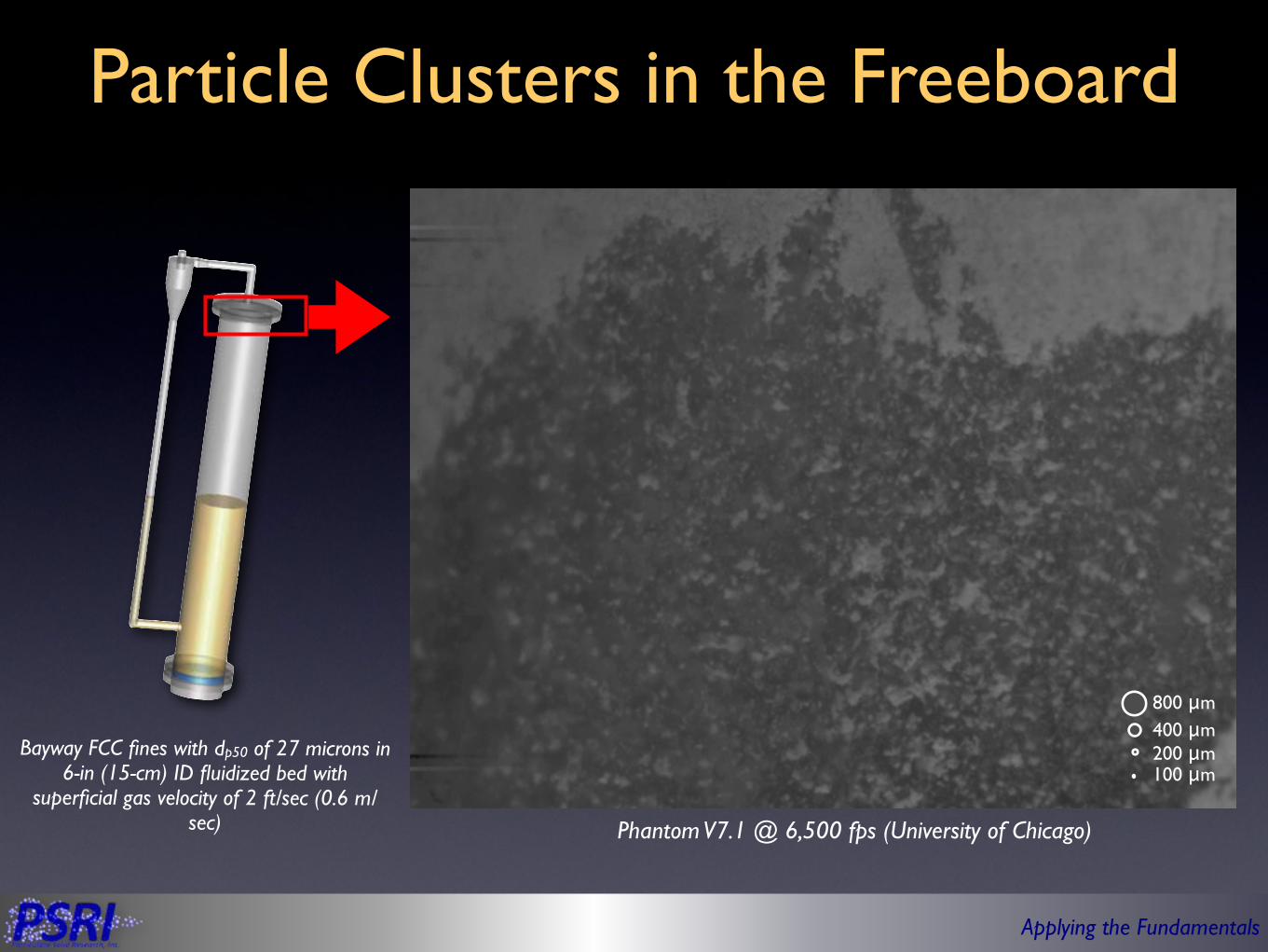
Particle Clusters in the Freeboard
800 μm400 μm200 μm100 μm
Phantom V7.1 @ 6,500 fps (University of Chicago)
Bayway FCC fines with dp50 of 27 microns in 6-in (15-cm) ID fluidized bed with
superficial gas velocity of 2 ft/sec (0.6 m/sec)

Applying the Fundamentals
Hypothesis: Particle Clusters
• Wilhelm and Kwauk postulated that particle clusters exist in 1948• Kaye and Boardman suggested that particle clusters are possible
when solids concentrations exceeded 0.05%• Yerushalmi et. al. proposed that particle clustering explained the
larger than expected slip velocity measured in a fast-fluidized bed• Geldart and Wong noted similar observations and conclusions
• Baeyens et. al. proposed that there is a critical particle size where clustering can occur• Karri et. al. noted similar findings
Higher Drag“Larger
Aerodynamic Diameter”
Wilhelm, R.H., Kwauk, M., Chemical Engineering Progress 44 (1948) 201.Kaye, B.M., Boardman, R.P., Proc. Symp. on the Interaction between Fluids and Particles, Inst. Chem. Eng., London, 17, 1962.Yerushalmi, J., Tuner, D.H., Squires, A.M., Industrial & Engineering Chemistry Process Design and Development 15 (1976)47–53.
Geldart, D., Wong, A.C.Y., AIChE Symp. Ser., 255 (1987), 1.Baeyens et al. Powder technology. 71 (1992) 71-80Karri, S.B.R., Knowlton, T.M., Internal Commnunication, 1990.
Applying the Fundamentals
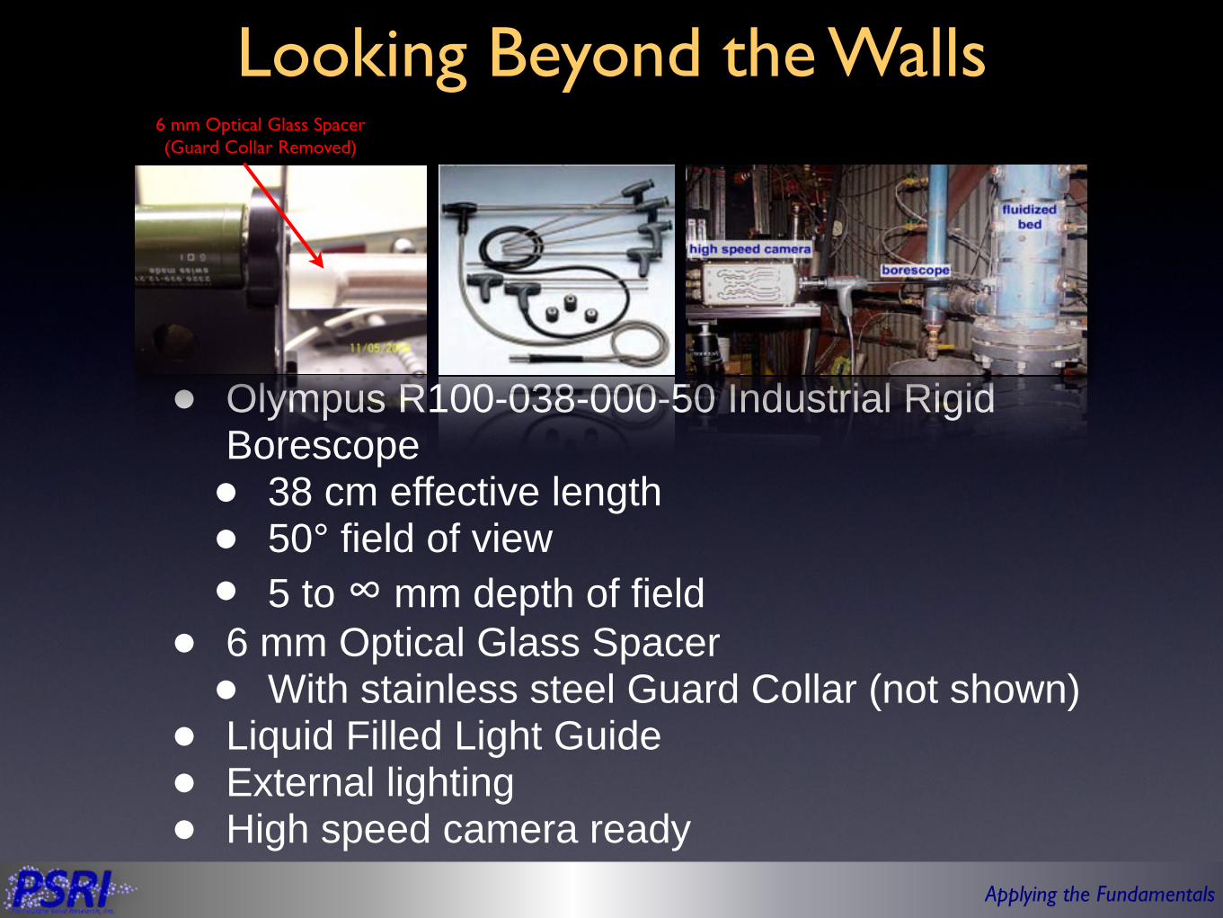
Looking Beyond the Walls
• Olympus R100-038-000-50 Industrial Rigid Borescope• 38 cm effective length• 50° field of view• 5 to ∞ mm depth of field
• 6 mm Optical Glass Spacer• With stainless steel Guard Collar (not shown)
• Liquid Filled Light Guide• External lighting• High speed camera ready
6 mm Optical Glass Spacer (Guard Collar Removed)

Applying the Fundamentals
Polyethylene Clusters in Freeboard
• Clusters can be traced and sized
• Average cluster size was 23 particles
Phantom V7.1 @ 4000 fps, 20 μs exposure (NETL)
Polyethylene with dp50 of 70
microns in 6-in (15-cm) ID
fluidized bed with superficial gas velocity of 1 ft/sec (0.3 m/
sec)

Applying the Fundamentals
FCC Catalyst Clusters in Freeboard
• 30% of the material in the freeboard was observed as clusters• Average cluster size was 11 particles
Phantom V7.1 @ 4000 fps, 20 μs exposure (NETL)
FCC powder with dp50 of 72 microns in 6-in
(15-cm) ID fluidized bed
with superficial gas velocity of 1 ft/sec (0.3 m/
sec)
←200 μm Diameter

Applying the Fundamentals
FCC Catalyst Clusters in the Fluidized Bed
• Cluster observed near bubble region• Can not distinguish if clusters are in the emulsion phase or not
Phantom V7.1 @ 4000 fps, 20 μs exposure (NETL)
FCC powder with dp50 of 72 microns in 6-in
(15-cm) ID fluidized bed
with superficial gas velocity of 1 ft/sec (0.3 m/
sec)
←50 μm Diameter
Applying the Fundamentals
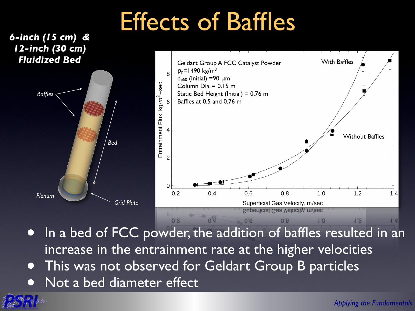
Effects of Baffles
• In a bed of FCC powder, the addition of baffles resulted in an increase in the entrainment rate at the higher velocities
• This was not observed for Geldart Group B particles• Not a bed diameter effect
Grid Plate
Baffles
Plenum
Bed
6-inch (15 cm) & 12-inch (30 cm) Fluidized Bed
‡ ‡ ‡‡
‡
‡‡
‡
‡
Ê Ê ÊÊ
ÊÊÊÊÊÊÊÊÊ
Ê
Ê
Ê
0.2 0.4 0.6 0.8 1.0 1.2 1.40
2
4
6
8
Superficial Gas Velocity, mêsec
Entra
inm
entF
lux,
kgêm2 -
sec
With Baffles
Without Baffles
Geldart Group A FCC Catalyst Powderρp=1490 kg/m3
dp50 (Initial) =90 μmColumn Dia. = 0.15 mStatic Bed Height (Initial) = 0.76 mBaffles at 0.5 and 0.76 m
‡‡
‡‡
‡
‡
‡
ÊÊ
ÊÊÊÊÊ
Ê
Ê
0.6 0.8 1.0 1.2 1.40.0
0.5
1.0
1.5
2.0
2.5
3.0
Superficial Gas Velocity, mêsec
Entra
inm
entF
lux,
kgêm2 -
sec
Geldart Group B Cokeρp=1600 kg/m3
dp50 (Initial) =150 μmColumn Dia. = 0.3 mStatic Bed Height (Initial) = 0.76 m
With Baffles
Without Baffles
‡ ‡ ‡‡
‡
‡‡
‡
‡
Ê Ê ÊÊ
ÊÊÊÊÊÊÊÊÊ
Ê
Ê
Ê
0.2 0.4 0.6 0.8 1.0 1.2 1.40
2
4
6
8
Superficial Gas Velocity, mêsec
Entra
inm
entF
lux,
kgêm2 -
sec
With Baffles
Without Baffles
Geldart Group A FCC Catalyst Powderρp=1490 kg/m3
dp50 (Initial) =90 μmColumn Dia. = 0.15 mStatic Bed Height (Initial) = 0.76 mBaffles at 0.5 and 0.76 m

Applying the Fundamentals
Effects of Baffles
• In a bed of FCC powder, the addition of baffles resulted in an increase in the entrainment rate at the higher velocities
• This was not observed for Geldart Group B particles• Not a bed diameter effect
Grid Plate
Baffles
Plenum
Bed
6-inch (15 cm) & 12-inch (30 cm) Fluidized Bed
‡ ‡ ‡‡
‡
‡‡
‡
‡
Ê Ê ÊÊ
ÊÊÊÊÊÊÊÊÊ
Ê
Ê
Ê
0.2 0.4 0.6 0.8 1.0 1.2 1.40
2
4
6
8
Superficial Gas Velocity, mêsec
Entra
inm
entF
lux,
kgêm2 -
sec
With Baffles
Without Baffles
Geldart Group A FCC Catalyst Powderρp=1490 kg/m3
dp50 (Initial) =90 μmColumn Dia. = 0.15 mStatic Bed Height (Initial) = 0.76 mBaffles at 0.5 and 0.76 m
‡‡
‡‡
‡
‡
‡
ÊÊ
ÊÊÊÊÊ
Ê
Ê
0.6 0.8 1.0 1.2 1.40.0
0.5
1.0
1.5
2.0
2.5
3.0
Superficial Gas Velocity, mêsec
Entra
inm
entF
lux,
kgêm2 -
sec
Geldart Group B Cokeρp=1600 kg/m3
dp50 (Initial) =150 μmColumn Dia. = 0.3 mStatic Bed Height (Initial) = 0.76 m
With Baffles
Without Baffles

Applying the Fundamentals
‡ ‡
‡ ‡‡‡ ‡‡
‡‡
‡‡
‡‡ ‡
‡ ‡‡
‡‡ ‡
‡ÚÚÚ Ú Ú Ú Ú
Ú
Ú
ÚÚ
Ú
Ú
0 2000 4000 6000 80000
5
10
15
20
25
30
120.
140.
160.
180.
Time, sec
Entra
inm
ent,
kg
Flui
dize
dBe
dH
eigh
t,cm
Effects of Bed Height
• Fines recycled back into the bed• At 4500 seconds, the bed height was decreased by 25%• Entrainment rate increase corresponded with drop in
bed height
Bed Height
Entrainment Total
25% Reduction in Bed Height
FCC Cyclone Fines (dp50=27 μm)Superficial Gas Velocity = 0.56 m/sec
6” (15 cm) ID X 6.1 m Tall Fluidized Bed
Grid PlatePlenum
Bed
Vent
Dipleg
Cyclone

Applying the Fundamentals
• Same material in the same unit• Entrainment rate was measured at various bed heights• Entrainment rate is inversely proportional to bed height
Grid PlatePlenum
Bed
Vent
Dipleg
Cyclone
Effects of Bed Height
6” (15 cm) ID X 6.1 m Tall Fluidized Bed
‡ ‡
‡
‡
‡
‡
60 80 100 120 140 160 1800
10
20
30
40
Fluidized Bed Height, cm
Entra
inm
entR
ate,
kgêhr
FCC Cyclone Fines (dp50=27 μm)Superficial Gas Velocity = 0.56 m/sec
Applying the Fundamentals
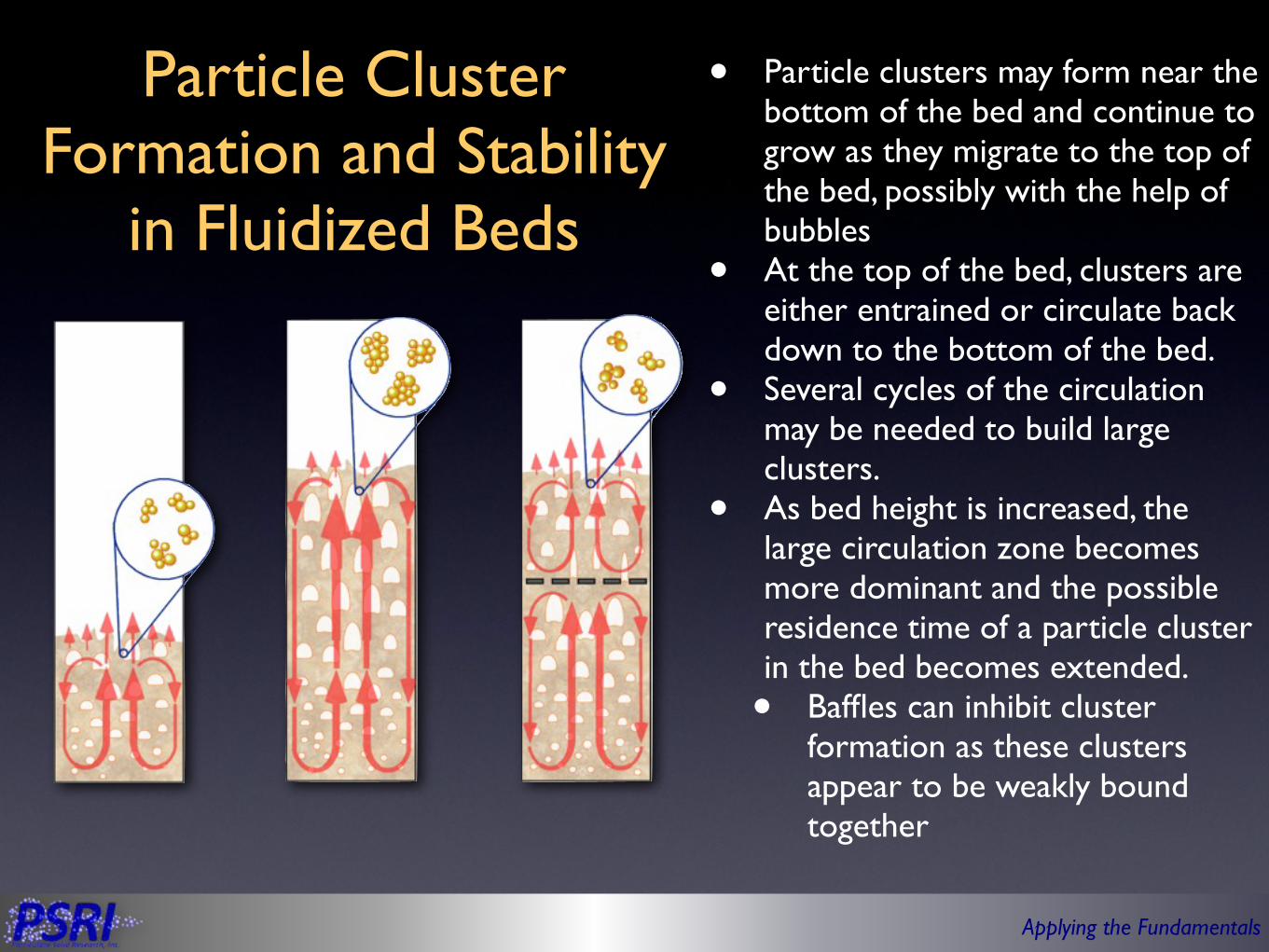
Particle Cluster Formation and Stability
in Fluidized Beds
• Particle clusters may form near the bottom of the bed and continue to grow as they migrate to the top of the bed, possibly with the help of bubbles
• At the top of the bed, clusters are either entrained or circulate back down to the bottom of the bed.
• Several cycles of the circulation may be needed to build large clusters.
• As bed height is increased, the large circulation zone becomes more dominant and the possible residence time of a particle cluster in the bed becomes extended. • Baffles can inhibit cluster
formation as these clusters appear to be weakly bound together
Applying the Fundamentals
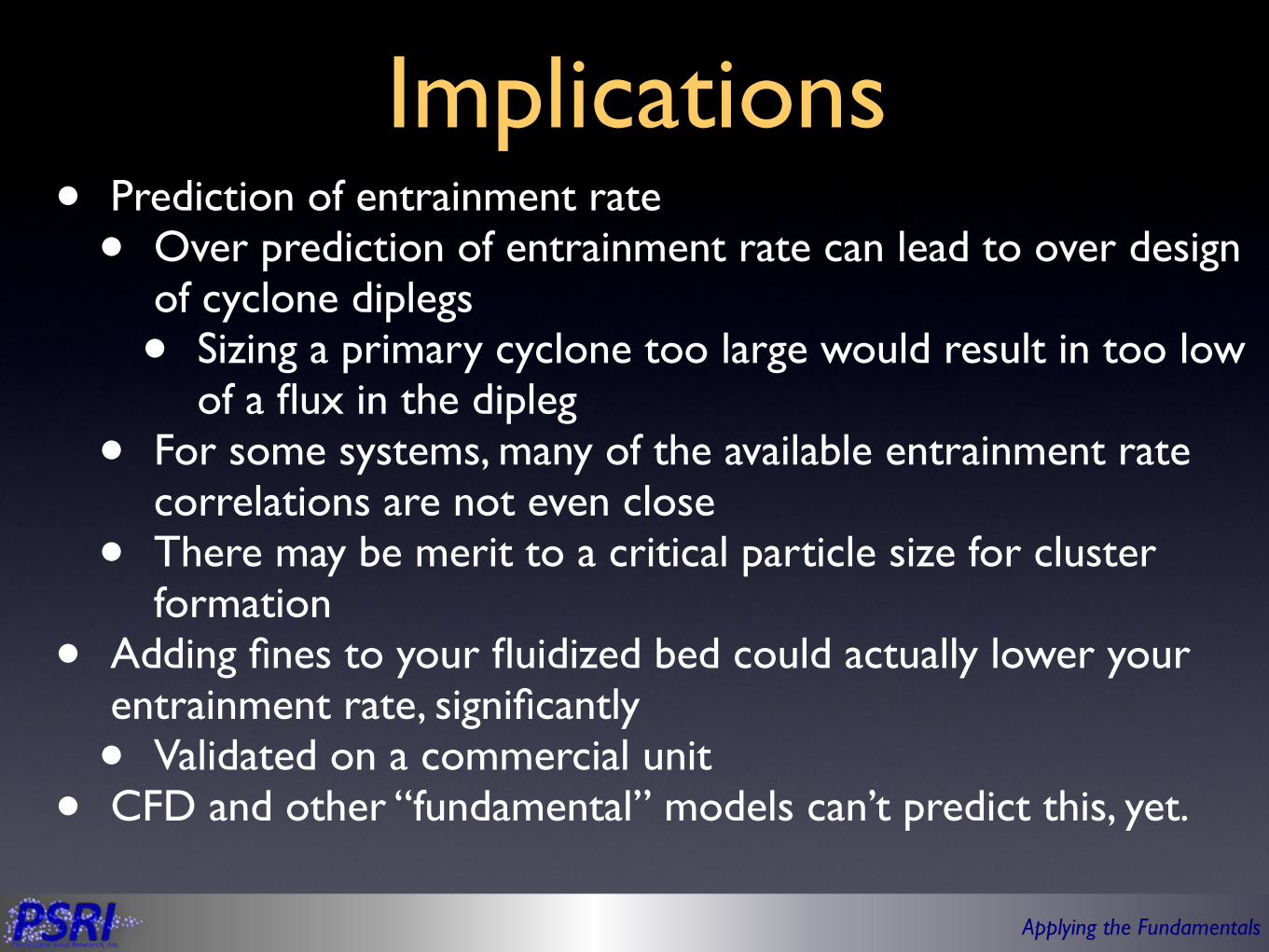
Implications• Prediction of entrainment rate
• Over prediction of entrainment rate can lead to over design of cyclone diplegs• Sizing a primary cyclone too large would result in too low
of a flux in the dipleg• For some systems, many of the available entrainment rate
correlations are not even close• There may be merit to a critical particle size for cluster
formation• Adding fines to your fluidized bed could actually lower your
entrainment rate, significantly• Validated on a commercial unit
• CFD and other “fundamental” models can’t predict this, yet.

Applying the Fundamentals
Outline
• Particle behavior and flow regimes• Bed behavior• Entrainment• Bubble• Multiphase jet• Summary

Applying the Fundamentals
Bubble Growth
• Bubbles in Group A particles are small and reach an equilibrium bubble size quickly
• Bubbles in Group B particles continue to grow and can get very large• Poor heat and mass transfer• Mechanical stresses
Applying the Fundamentals
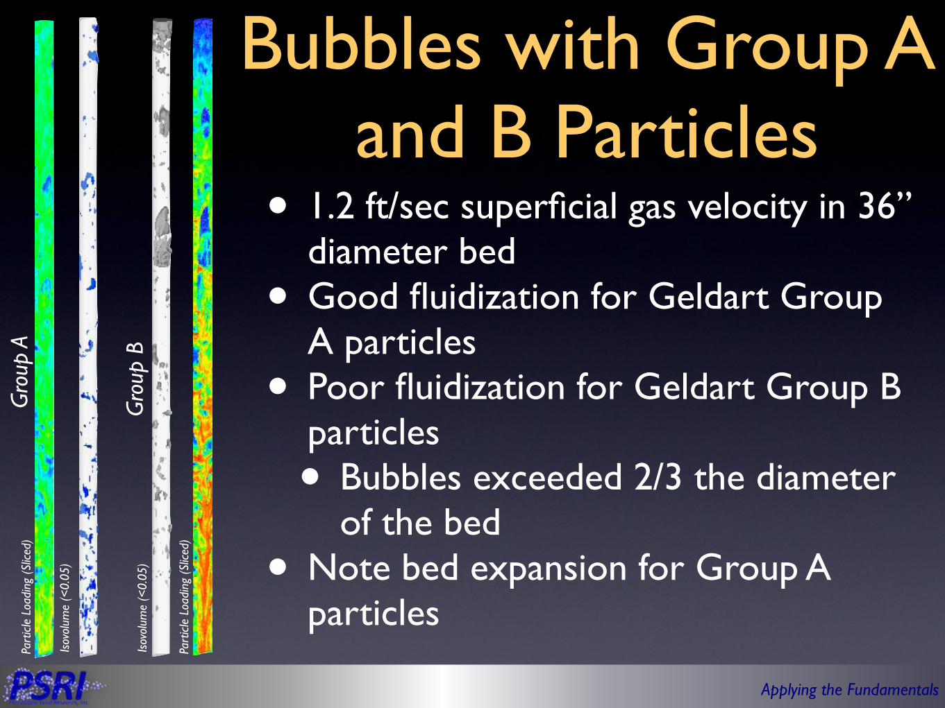
Bubbles with Group A and B Particles
• 1.2 ft/sec superficial gas velocity in 36” diameter bed
• Good fluidization for Geldart Group A particles
• Poor fluidization for Geldart Group B particles• Bubbles exceeded 2/3 the diameter
of the bed• Note bed expansion for Group A
particles
Gro
up A
Gro
up B
Isov
olum
e (<
0.05
)
Part
icle
Loa
ding
(Sl
iced
)
Isov
olum
e (<
0.05
)
Part
icle
Loa
ding
(Sl
iced
)

Applying the Fundamentals
Should They Be Called Bubbles
Applying the Fundamentals
Outline
• Particle behavior and flow regimes• Bed behavior• Entrainment• Bubble• Multiphase jet• Summary

Applying the Fundamentals
Outline
• Particle behavior and flow regimes• Bed behavior• Jetsam/floatsam?
• Entrainment• Bubble• Multiphase jet• Gas jets• Gas-solid jets• Gas-liquid jets
• Summary
Applying the Fundamentals
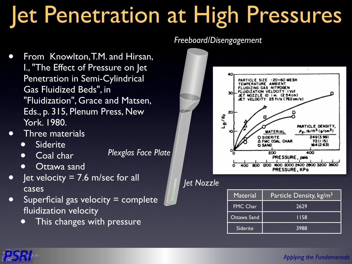
Jet Penetration at High Pressures
• From Knowlton, T.M. and Hirsan, I., "The Effect of Pressure on Jet Penetration in Semi-Cylindrical Gas Fluidized Beds", in "Fluidization", Grace and Matsen, Eds., p. 315, Plenum Press, New York. 1980.
• Three materials• Siderite• Coal char• Ottawa sand
• Jet velocity = 7.6 m/sec for all cases
• Superficial gas velocity = complete fluidization velocity• This changes with pressure
Jet Nozzle
Plexglas Face Plate
Freeboard/Disengagement
Material Particle Density, kg/m3
FMC Char 2629
Ottawa Sand 1158
Siderite 3988

Applying the Fundamentals
Simulations: Particle Density EffectsCharSiderite Sand
Material Particle Density, kg/m3
FMC Char
2629
Ottawa Sand
1158
Siderite 3988
Lower Density
Applying the Fundamentals
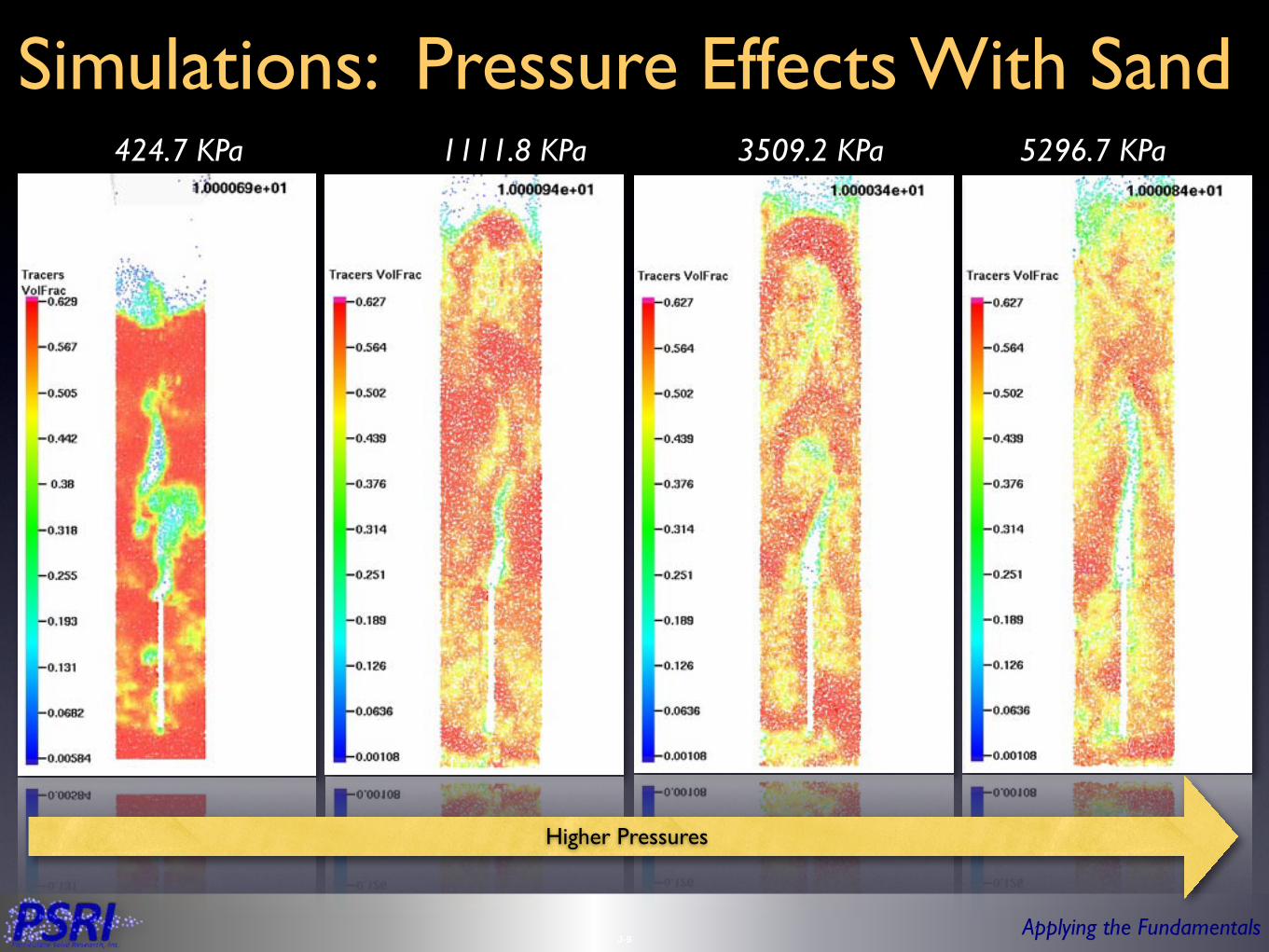
Simulations: Pressure Effects With Sand424.7 KPa 1111.8 KPa 3509.2 KPa 5296.7 KPa
J-9
Higher Pressures
Applying the Fundamentals
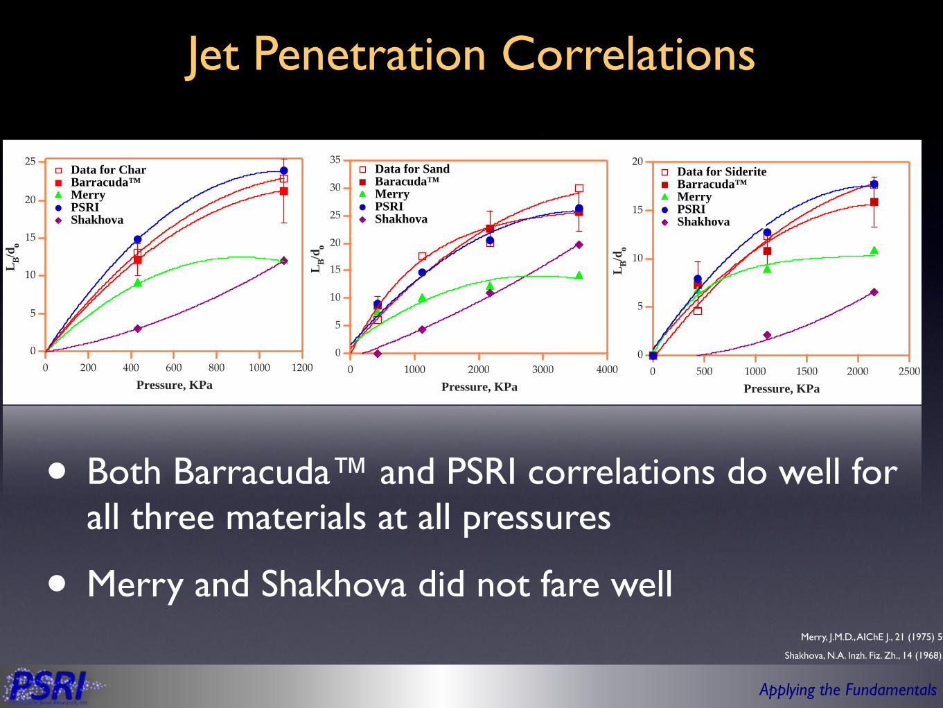
Jet Penetration Correlations
• Both Barracuda™ and PSRI correlations do well for all three materials at all pressures
• Merry and Shakhova did not fare well
Shakhova, N.A. Inzh. Fiz. Zh., 14 (1968) 61
Merry, J.M.D., AIChE J., 21 (1975) 507
25
20
15
10
5
0
L B/d o
120010008006004002000Pressure, KPa
Data for Char Barracuda™ Merry PSRI Shakhova
35
30
25
20
15
10
5
0
L B/d o
40003000200010000Pressure, KPa
Data for Sand Baracuda™ Merry PSRI Shakhova
20
15
10
5
0
L B/d o
25002000150010005000Pressure, KPa
Data for Siderite Barracuda™ Merry PSRI Shakhova
Applying the Fundamentals
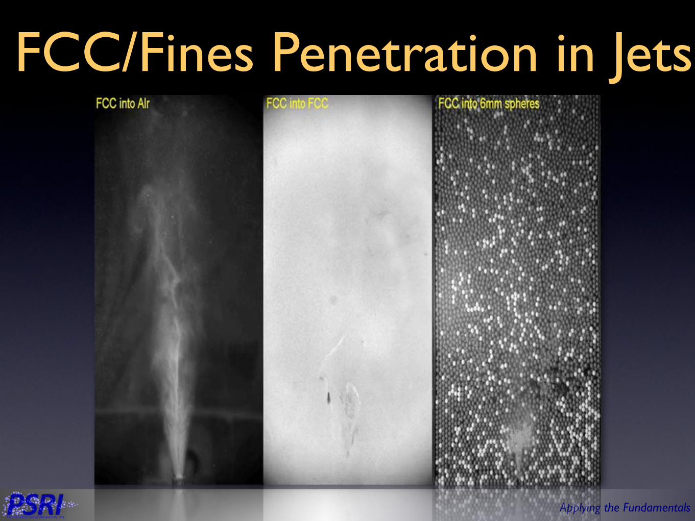
FCC/Fines Penetration in Jets
Applying the Fundamentals
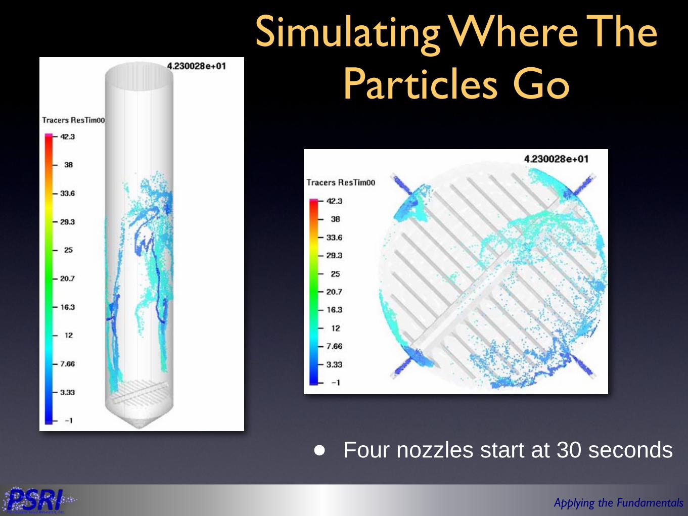
Simulating Where The Particles Go
• Four nozzles start at 30 seconds

Applying the Fundamentals
Biomass Injection
• Penetration does not go far from the wall
Top Injectors
Middle Injectors
Bottom Injectors
Applying the Fundamentals
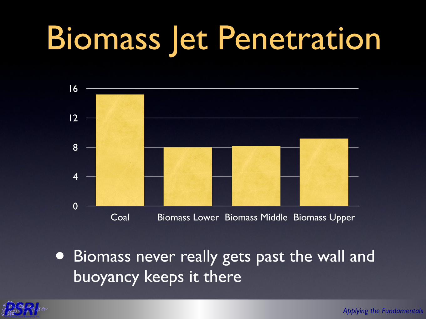
Biomass Jet Penetration
• Biomass never really gets past the wall and buoyancy keeps it there
0
4
8
12
16
Coal Biomass Lower Biomass Middle Biomass Upper

Applying the Fundamentals
Particle Laden Jets via PSRI Jet Penetration Correlation
• Particle momentum form a jet significantly increase the jet penetration length
0 20 40 60 80 1000.0
0.1
0.2
0.3
0.4
Jet Velocity, mêsec
JetP
enet
ratio
n,M
Gas Only
100 kg/m2-sec
200 kg/m2-sec
300 kg/m2-sec
Air and Air-Sand Particles into a Fluidized Bed of Sand at 103 KPa and 800°C

Applying the Fundamentals
Jet Penetration Length
0 20 40 60 800
5
10
15
20
Jet Velocity, ftêsec
JetP
enet
ratio
nN
umbe
r,Pêdo
Gas Jet into CoalGas Jet into Sand
Gas-Coal Jet into Coal
Gas-Biomass Jet into Sand

Applying the Fundamentals
Liquid Injection
into a Fluidized
Bed2D Fluidized Bed
Secondary Cyclone
Primary Cyclone
Standpipe
Riser
Nozzle
Plexiglas™
Sparger
Applying the Fundamentals
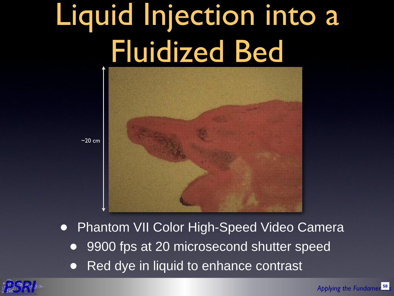
Liquid Injection into a Fluidized Bed
• Phantom VII Color High-Speed Video Camera
• 9900 fps at 20 microsecond shutter speed
• Red dye in liquid to enhance contrast
~20 cm
58

Applying the Fundamentals
8-inches (20 cm) from injector face
Liquid Injection into a Fluidized Bed
• Phantom VII Color High-Speed Video Camera• 9900 fps at 20 microsecond shutter speed• With liquid dye for contrast
1cm
2-inches (5 cm) from injector face
59

Applying the Fundamentals
Jet - Fluidized Bed Boundary Layer
• Little liquid jet penetration after initial wetting of particles
• Little particle exchange between wetted particles and dry particles beyond boundary
• Boundary layer estimated at 0.18 ± 0.04 cm

Applying the Fundamentals
Jet - Fluidized Bed Boundary Layer
• Little liquid jet penetration after initial wetting of particles
• Little particle exchange between wetted particles and dry particles beyond boundary
• Boundary layer estimated at 0.18 ± 0.04 cm

Applying the Fundamentals
Liquid-Particle Interactions in a Fluidized Bed
• 1000 fps at 990 microsecond shutter speed
• 5-inches (12.7-cm) from nozzle face
• 1.5-inches (3.8-cm) from face plate (wall)• Estimated to be within
the of jet• 20 SCFH (0.6 SCMH)
sweeping gas• Liquid injection contains
dye• Small particles coating
liquid droplets

Applying the Fundamentals
Liquid-Particle Interactions in a Fluidized Bed
• 1000 fps at 990 microsecond shutter speed
• 9-inches (23-cm) from nozzle face
• 1.0-inches (2.5-cm) from face plate (wall)
• Estimated to be at the boundary of the jet
• 5 SCFH (0.15 SCMH) sweeping gas
• Liquid injection contains dye
• Bigger particles coating droplets

Applying the Fundamentals
Summary• Particle properties under reaction conditions (including particle
size) are a key design parameters• Geldart Group A powders have small bubbles even in large units
• Smoother fluidization • Significant bed expansion especially at higher pressures• Good heat and mass transfer• Gas bypassing could be an issue• Particle clustering could be an issue
• Geldart Group B powders have large bubbles in commercial units• Poorer heat and mass transfer• Unstable bed operations in some cases• Slugging could be an issue, even in commercial units
• Jet penetration is mostly driven by buoyancy!


